1
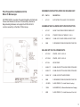
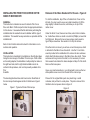
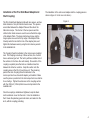
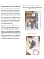
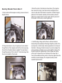
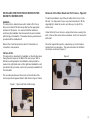
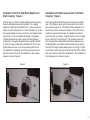
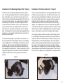
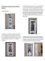
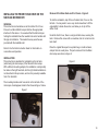
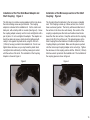
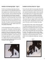
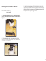
Nikon Focus Drive Manual
P RIO R S CIEN TIFIC I NC ., 80 R ESERVOIR PARK D RIVE , R OCKLAND , MA 02370-1062
T ELEPHONE 781-878-8442 F AX 781-878-8736
WWW. PRIOR . COM
Table of Contents
Safety Information.................................................................1
Unpacking the System..........................................................1
Focus Drive Installation Instructions for Nikon Ti.............2
Mounting Z Encoder Probe on Nikon Ti..............................6
Focus Drive Installation Instructions for Nikon FN1..........8
Mounting Z Encoder Probe on Nikon FN1..........................11
Focus Drive Installation Instructions for Nikon 80i..........13
Mounting Z Encoder Probe on Nikon 80i..........................17
RS232 Command Set..........................................................18
P RIO R S CIENTIFIC I NC ., 80 R ESERVOIR PARK D RIVE , R OCKLAND , MA 02370-1062
T ELEPHONE 781-878-8442 F AX 781-878-8736
WWW. PRIOR . COM
Important Safety Information
Unpacking the System
• Save this manual as it contains important safety information and
operating instructions.
• Save this manual as it contains important safety information and
operating instructions.
• Before using the stage system, please follow and adhere to all
warnings, safety and operating instructions located on the product
and in this User’s Manual.
• Before using the stage system, please follow and adhere to all
warnings, safety and operating instructions located on the product
and in this User’s Manual.
• Do not expose the product to water or moisture.
• Do not expose the product to water or moisture.
• Do not expose the product to extreme hot or cold temperatures.
• Do not expose the product to extreme hot or cold temperatures.
• Do not expose the product to open flames.
• Do not expose the product to open flames.
• Do not allow objects to fall on or liquids to spill on the product.
• Do not allow objects to fall on or liquids to spill on the product.
• Connect the AC power cord only to designated power sources as
marked on the product.
• Connect the AC power cord only to designated power sources as
marked on the product.
• Make sure the electrical cord is located so that it will not be
subject to damage.
• Make sure the electrical cord is located so that it will not be subject
to damage.
• To reduce the risk of damage, unplug the product from the power
source before connecting the components together.
• To reduce the risk of damage, unplug the product from the power
source before connecting the components together.
• DANGER - never alter the AC cord or plug. If the plug will not fit
into the outlet, have a proper outlet installed by a qualified
electrician.
• DANGER - never alter the AC cord or plug. If the plug will not fit
into the outlet, have a proper outlet installed by a qualified electrician.
• Use only the proper type of power supply cord set (provided with
the system) for this unit.
• Do not attempt to disassemble the product. Doing so will void the
warranty. This product does not contain consumer serviceable
components. Service should be performed by Authorized
Service Centers.
• Use only the proper type of power supply cord set (provided with
the system) for this unit.
• Do not attempt to disassemble the product. Doing so will void the
warranty. This product does not contain consumer serviceable
components. Service should be performed by Authorized Service
Centers.
1
Prior Focus Drive Installation Kit for
Nikon Ti Microscope
REFERENCE INSTRUCTION, PRINT AND INCLUDE IN KIT:
QTY
PART #
DESCRIPTION
FACTORY NOTE: Assemble Threaded Standoffs with Flat Head
Screws and Washers as shown in the assembly view below.
Bag remaining hardware, and supply kit with this kit list for
customer assembly on the Nikon Ti Microscope.
1
HP 1211
INST INSTRUCTION, NIKON TI FOCUS DRIVE
ASSEMBLE THE FOLLOWING PARTS PER INSTRUCTION:
1
HP 1207
NIKON TI MOUNTING INTERFACE BRACKET
2
HP 1208
STANDOFF, 5MM X .8 THREAD X 1.06 LG
2
5MM X .8 P
16 MM LG FLAT HEAD SCREW, HEX SKT DRIVE
4
5MM
FLATWASHER,STAINLESS,10MM ODX.75MM THK
BAG AND KIT THE FOLLOWING PARTS:
1
HP 1209-1
SPACER, .250 ID X .360 LG
1
HP 1209-2
SPACER, .250 ID X .500 LG
1
HP 1244
KNOB COVER
1
6 MM X 1P
20 MM LONG BUTTON HEAD SCREW, STAINLESS
1
6 MM X 1P
25 MM LONG BUTTON HEAD SCREW, STAINLESS
2
5 MM X .8 P
25 MM LG SOCKET HEAD SCREWS
4
5MM
FLATWASHER,STAINLESS,10MM ODX.75MM THK
1
.050 INCH
ALLEN WRENCH (To Install Flexible Coupling)
1
1.5MM
ALLEN WRENCH (To Remove Nikon Brass Knob Coupling)
1
4MM
ALLEN WRENCH (To Install Bracket and Drive Unit)
2
INSTALLING THE PRIOR FOCUS DRIVE ON THE
NIKON TI MICROSCOPE
GENERAL:
This instruction is intended as an aid to install a Prior Focus
Drive onto Nikon Ti Microscope that has the appropriate interface
for this device. It is assumed that the technician performing the
installation has the needed tools and is familiar with this type of
installation. The needed hex key wrenches are provided with the
installation kit.
Refer to the Controller instruction sheet for information on connections and operation.
INSTALLATION:
This instruction is described for installation on the left side (when
facing the microscope) of the Nikon Ti microscope. With a different mounting adapter, the installation could possibly be made on
the right hand side, but this right hand installation is not described in this procedure, and no kit is presently available from
Prior
Scientific.
The mounting interface holes and focus knob on the left side of
the microscope should appear similar to that shown in figure 1
below.
Figure 1: Typical Left Side of Microscope
Removal of the Nikon Knob and Port Covers - Figure 2:
To start the installation, slip off the soft rubber Knob Cover on the
left side. You may need to use a very small screwdriver to lift the
edge slightly to break the suction, and allow you to slip off the
rubber cover.
Under the Knob Cover, there are two holes, about 4 mm in diameter. Inside these holes are small cross slotted (Phillips) screws that
hold the knob. Remove the two screws using a small, jeweler’s
type Phillips screwdriver. Be careful not to drop the screws.
Once the knob is removed, you will see a round brass piece, which
is attached to the Nikon focus drive shaft. Use the 1.5 mm Allen
wrench provided in the installation kit to remove the two setscrews
which attach this brass piece to the Nikon focus drive shaft. These
setscrews sit in a groove in the shaft, so it is necessary to loosen
them several turns before this brass adapter will slip off of the shaft.
Remove this brass piece.
Use a very small screwdriver or your fingernails to remove the two
white plastic screw covers from the side of the microscope.
Place all of the original Nikon parts in a plastic bag or small
container, and put them in a safe place. The parts removed from
the Nikon microscope are shown in figure 2:
Figure 2:
3
Installation of the Prior Side Mount Adapter and
Shaft Coupling:
The Prior Side Mount Adapter installs with two spacers, and two
6mm diameter x 1mm pitch button head screws. The spacers
are installed between the Adapter Plate and the side of the
Nikon microscope. The shorter of the two spacers and the
shorter button head screw are used to secure the bottom edge
of the Adapter Plate. The longer button head screw and the
longer spacer are used on the top edge of the Adapter Plate.
Visually center the knob in the hole of the adapter plate, and
tighten this hardware securely using the 4mm hex key wrench
in the installation kit.
The installation of the side mount adapter and the coupling pieces is
shown in figure 3. Knob cover not shown.)
Figure 3:
The Coupling Piece that attaches to the microscope is installed
next. The Coupling is made up of three sections, two of which
have a setscrew type hub. The factory will have installed one of
the sections on the focus drive unit already. One section of the
coupling is a plastic piece that acts as a flexible connection
between the other two sections. Snap this section onto the
coupling piece on the Prior Focus Drive unit. The remaining
piece is the 4mm Coupling Piece that attaches to the
microscope fine focus drive shaft adapter, just installed. Make
sure this piece is pushed onto the microscope fine focus shaft as
far as it will go. Tighten the setscrews on this coupling section
with the .050 inch (1.25mm) Allen hex wrench provided in the
installation kit.
Once the coupling is installed and tightened, snap the black
knob mechanism cover into the knob. It must be installed so
that it clears the planetary gear mechanism, and seats into the
knob, with the coupling protruding.
4
Installation of the Focus Drive Unit: Figures 4 & 5
The Focus Drive Unit installs to the mounting adapter with two
5mm x 25mm long socket head screws. Hold the Focus Drive
Unit in position, lining up the Coupling Piece installed on the
microscope with the slot in the plastic section of the coupling,
which was previously installed on the Focus Drive Unit. Install
the two 5mm x 25mm socket head screws, and mount the Focus
Drive to the Adapter Bracket. Do not tighten these screws yet.
Adjust the final position of the Housing to line up the coupling so
that it is as centered on the other section as possible. Lightly
tighten the Focus Drive mounting screws. At this point, you
need to look carefully at the coupling.
The Coupling should just make connection, without being
crushed. If the coupling is being squeezed, washers are provided with the installation kit and can be added between the
Drive Housing and the Threaded Spacers on the Mounting
Adapter Plate. The unit is shipped with two washers already installed between the mounting plate and the spacers. If the coupling does not make connection, washers can be removed. The
idea is to add or remove a washer so that the coupling makes
connection without being squeezed. Once this position is correct, fully tighten the mounting screws. See figure 4 below.
Figure 4 - The washers between the Spacer and the Adapter Plate
may be removed, or another washer may be added so that the
coupling connects properly.
Figure 5 - Final installation
5
Mounting Z Encoder Probe to Nikon Ti
1. Remove the two M5 nosepiece mounting screws as shown in
the photo below.
3. Mount the probe to the bracket as shown below. (The stage has
been removed for clarity.) Insert the metal rod and tighten the set
screw on each side of the bracket to secure the rod. Slide the appropriate end of the “knuckle” assembly onto the encoder probe and
tighten only enough to hold it in place. Finally, slide the open end of
the “knuckle” onto the rod (no need to tighten yet).
2. Place probe bracket on top of nosepiece and screw bracket
through the top of the nosepiece and into the microscope using
the two M5 x 40 captive fasteners supplied. The view below is
through the opening of Prior model H117 motorized stage. Note
the correct orientation of the bracket.
4. Install the stage, taking care that there is sufficient clearance
between the probe assembly and the stage. Adjust the position of the
encoder probe so that it makes contact perpendicular to a flat area of
the bottom of the stage. Rotate the coarse focus knob and adjust the
probe assembly accordingly to ensure contact with the bottom of the
stage throughout the required range of travel. (Make sure that the
probe does not impede the focus mechanism at the lower limit of
travel.) When satisfied with the position of the probe, tighten the entire
assembly to prevent slippage. The complete assembly should
resemble the photo below.
6
INSTALLATION KIT:
REFERENCE INSTRUCTION, PRINT AND INCLUDE IN KIT:
FACTORY NOTE: Assemble Threaded Standoffs with long set
screws and Washers as shown in the assembly view below.
Bag remaining hardware, and supply kit with this kit list for
customer assembly on the Nikon FN1 Microscope.
QTY PART #
1
HP 1221
DESCRIPTION
INST INSTRUCTION, NIKON FN1 FOCUS DRIVE
ASSEMBLE THE FOLLOWING PARTS PER SHEET 1 INSTRUCTION:
1
HP 1210
NIKON FN1 MOUNTING INTERFACE BRACKET
2
HP 1243
STANDOFF, 5MM X .8 THREAD
4
5MM
FLATWASHER,STAINLESS,10 MM ODX
.75 MM THK
2
5 MM X .8P 20 MM LG SOCKET SET SCREWS
1
5 MM X .8 P 30 MM LG SOCKET HEAD SCREW
BAG AND KIT THE FOLLOWING PARTS:
1
EMI 326
COUPLING ADAPTER
2
5 MM X .8 P 25 MM LG SOCKET HEAD SCREWS
4
5MM
FLATWASHER,STAINLESS,10 MM ODX
.75 MM THK
1
.050 INCH
ALLEN WRENCH (To Install Flexible Coupling)
1
4MM
ALLEN WRENCH (To Install Bracket & Drive Unit)
7
INSTALLING THE PRIOR FOCUS DRIVE ON THE
NIKON FN1 MICROSCOPE
GENERAL:
This instruction is intended as an aid to install a Prior Focus
Drive onto a Nikon FN1 Microscope that has the appropriate
interface for this device. It is assumed that the technician
performing the installation has the needed tools and is familiar
with this type of installation. The needed hex key wrenches are
provided with the installation kit.
Refer to the Controller instruction sheet for information on
connections and operation.
INSTALLATION:
This instruction is described for installation on the left side (when
facing the microscope) of the Nikon FN1 microscope. With a
different mounting adapter, the installation could possibly be
made on the right hand side, but this right hand installation is not
described in this procedure, and no kit is presently available from
Prior Scientific.
Removal of the Nikon Knob and Port Covers - Figure 2:
To start the installation, slip off the soft rubber Knob Cover on the
left side. You may need to use a very small screwdriver to lift the
edge slightly to break the suction, and allow you to slip off the
rubber cover.
Under the Knob Cover, there is a single slotted screw, securing the
knob. Remove this screw with a screwdriver, but do not remove the
knob itself.
Place the original Nikon parts in a plastic bag or small container,
and put them in a safe place. The parts removed from the Nikon
microscope are shown in figure 2.
Figure 2
The mounting interface and focus knob on the left side of the
microscope should appear similar to that shown in figure 1 below.
Figure 1 - Typical Left Side of Microscope
8
Installation of the Prior Side Mount Adapter and
Shaft Coupling: Figure 3
Installation of the Microscope section of the Shaft
Coupling: Figure 4
The first step is to install a coupling adapter into the hole where
the knob retaining screw was just removed. The coupling
adapter is contained in the installation kit. It is the small round
black part, with a stubby shaft on one side (See figure 3). Screw
the coupling adapter securely over the knob, and tighten it with a
pair of pliers. Do not over-tighten the adapter. The adapter
contains three allen set screws, which should be tightened
sufficiently to lock against the plastic knob, using the .050 inch
(1.25mm) hex key provided in the installation kit. Do not overtighten these setscrews, as you may break the plastic knob.
Just tighten them sufficiently so that they make good contact
with the surface of the knob. The installation of the coupling
adapter is shown in figure 3.
The Coupling Piece that attaches to the microscope is installed
next. The Coupling is made up of three sections, two of which
have a setscrew type hub. The factory will have installed one of
the sections on the focus drive unit already. One section of the
coupling is a plastic piece that acts as a flexible connection between the other two sections. Snap this section onto the coupling
piece on the Prior Focus Drive unit. The remaining piece is the
4mm Coupling Piece that attaches to the Microscope fine focus
Coupling Adapter, just installed. Make sure this piece is pushed
onto the microscope Coupling Adapter as far as it will go. Tighten
the setscrews on this coupling section with the .050 inch (1.25mm)
Allen hex wrench provided in the installation kit. The installation of
the coupling pieces is shown in figure 4.
Figure 3
Figure 4
9
Installation of the Mounting Adapter Plate: Figure 5
Installation of the Focus Drive Unit: Figure 6
The Prior Focus Drive Mounting Adapter should be installed
next. This mounting adapter attaches to the friction adjustment
knob on the Nikon scope, which is the innermost knob on the
left side. Start by checking the existing setting of the friction adjustment on the microscope. Use a piece of tape to mark any
convenient point on the side of the friction adjustment knob.
Count and record the number of turns to turn the knob all the
way in (clockwise) from your starting position. Now turn the
knob 6 turns out, but at least as many turns “out” as it was initially. This adjustment controls the load holding capability of the
microscope, so you need to maintain at least as much load capability as existed initially.
The Focus Drive Unit installs to the mounting adapter with two 5mm
x 25mm long socket head screws. Hold the Focus Drive Unit in position, lining up the Coupling Piece installed on the microscope with
the slot in the plastic section of the coupling, which was previously
installed on the Focus Drive Unit. Install the two 5mm x 25mm
socket head screws, and mount the Focus Drive to the Mounting
Adapter. Do not tighten these screws yet. Adjust the final position
of the Housing to line up the coupling so that it is as centered on the
other section as possible. Lightly tighten the Focus Drive mounting
screws. At this point, you need to look carefully at the coupling.
The Prior Mounting Adapter only installs in one direction, and
has a stop machined into the adapter. Make sure the clamping
screw is slightly loose, and the Adapter is positioned as shown
in Figure 5. A 4mm hex key is included in the installation kit.
Slide the Adapter over the friction adjustment knob until it bottoms against the machined stop. It may be necessary to pry the
clamp apart slightly with a screwdriver to ease the installation.
Tighten the clamp screw securely using the 4mm hex key
wrench.
The Coupling should just make connection, without being crushed.
If the coupling is being squeezed, washers are provided with the installation kit and can be added between the Drive Housing and the
Threaded Spacers on the Mounting Adapter. The unit is shipped
with two washers already installed between the mounting plate and
the spacers. If the coupling does not make connection, washers
can be removed. The idea is to add or remove a washer so that the
coupling makes connection without being squeezed. Once this position is correct, fully tighten the mounting screws. See figure 6 below.
Figure 6
Figure 5
10
Nikon FN1 Encoder Installation Kit
FACTORY NOTE: Bag the following hardware, and supply kit
with this kit list and installation instruction for customer assembly
on the Nikon FN1 Microscope.
REFERENCE INSTRUCTION, PRINT & INCLUDE COPY IN KIT:
QTY PART #
DESCRIPTION
1
INSTRUCTION, ENCODER ON NIKON FN1
HP 1245
BAG AND KIT THE FOLLOWING:
1
HP 1233
ENCODER MOUNTING PLATE ASSEMBLY
1
W 2523
ELECTRONIC ENCODER
1
WP 1100
15 PIN D - F-F GENDER CHANGER
(Attach to Encoder)
1
HP 1230
ACTUATOR BLOCK
(Note: Installs on FN1 Actuator Pin with two
3mm setscrews included in this kit)
2
3MM X .5MM 3MM LONG CUP POINT SETSCREW
(For Actuator Block)
2
4 MM X .7 P 12 MM LG BUTTON HEAD SCREWS
(Install Plate)
2
4MM
FLATWASHER (STAINLESS) (Install Plate)
1
1.5MM
ALLEN WRENCH (Actuator Installation)
1
3MM
ALLEN WRENCH (To Install Plate Assy)
11
Instructions for mounting Z limits & Encoder to
Nikon FN1
1. Remove back plate
2. Center the round rod which moves with the focus within its
travel. Roughly place the limits equi-distant from either side of
the rod and attach the limit plate and limits to the FN1 using the
2 M4 SHCS provided as shown below. Do not attach the
encoder yet.
3. Attach the limit/encoder actuator to the round rod and tighten the
2 set screws. Make sure to allow for a gap between the actuator
and the limit plate. The actuator should be oriented as shown below
so that it strikes the limits squarely. At this point make sure that the
microscope focus travel allowed by the limits is within the required
focus range for the specimens under observation. The limit plate
can be adjusted approximately 3mm from the top of travel to the
bottom of travel.
4. Attach the encoder probe and adjust the encoder clamp height
so that the encoder tip remains in contact with the actuator throughout the entire focus travel. Replace the back panel, carefully feeding
the encoder and the limit wires through the slot in the panel
12
PRIOR FOCUS DRIVE INSTALLATION KIT FOR
NIKON 80i MICROSCOPE
INSTALLATION KIT:
REFERENCE INSTRUCTION, PRINT AND INCLUDE IN KIT
FACTORY NOTE: Assemble threaded standoffs with long set
screws and washers as shown in the assembly view below. Bag
remaining hardware, and supply kit with this kit list for customer
assembly on the Nikon 80i Microscope.
QTY
PART #
DESCRIPTION
1
HP 1222 INST INSTRUCTION, NIKON 80 I FOCUS DRIVE
ASSEMBLE THE FOLLOWING PARTS PER SHEET 1 INSTRUCTION:
1
HP 1220
NIKON 80I MOUNTING INTERFACE BRACKET
2
HP 1223
STANDOFF, 5MM X .8 THREAD
4
5MM
FLATWASHER,STAINLESS,10 MM
OD X .75 MM THK
2
5 MM X .8P
20 MM LG SOCKET SET SCREWS
1
5 MM X .8 P
30 MM LG SOCKET HEAD SCREW
BAG AND KIT THE FOLLOWING PARTS:
1
EMI 326
COUPLING ADAPTER
2
5 MM X .8 P
25 MM LG SOCKET HEAD SCREWS
4
5MM FLATWASHER,STAINLESS,10 MM OD X .75 MM THK
1
.050 INCH
ALLEN WRENCH (To Install Flexible
Coupling)
1
4MM
ALLEN WRENCH (To Install Bracket
and Drive Unit)
13
INSTALLING THE PRIOR FOCUS DRIVE ON THE
NIKON 80i MICROSCOPE
GENERAL:
This instruction is intended as an aid to install a Prior Focus
Drive onto a Nikon 80i Microscope that has the appropriate
interface for this device. It is assumed that the technician performing the installation has the needed tools and is familiar with
this type of installation. The needed hex key wrenches are
provided with the installation kit.
Refer to the Controller instruction sheet for information on
connections and operation.
INSTALLATION:
This instruction is described for installation on the left side
(when facing the microscope) of the Nikon 80I microscope.
With a different mounting adapter, the installation could possibly
be made on the right hand side, but this right hand installation is
not described in this procedure, and no kit is presently available
from Prior Scientific.
Removal of the Nikon Knob and Port Covers - Figure 2:
To start the installation, slip off the soft rubber Knob Cover on the
left side. You may need to use a very small screwdriver to lift the
edge slightly to break the suction, and allow you to slip off the
rubber cover.
Under the Knob Cover, there is a single slotted screw, securing the
knob. Remove this screw with a screwdriver, but do not remove the
knob itself.
Place the original Nikon parts in a plastic bag or small container,
and put them in a safe place. The parts removed from the Nikon
microscope are shown in figure 2.
Figure 2
The mounting interface and focus knob on the left side of the
microscope should appear similar to that shown in figure 1 below.
Figure 1
14
Installation of the Prior Side Mount Adapter and
Shaft Coupling: Figure 3
Installation of the Microscope section of the Shaft
Coupling: Figure 4
The first step is to install a coupling adapter into the hole where
the knob retaining screw was just removed. The coupling
adapter is contained in the installation kit. It is the small round
black part, with a stubby shaft on one side (See figure 3). Screw
the coupling adapter securely over the knob, and tighten it with a
pair of pliers. Do not over-tighten the adapter. The adapter contains three allen set screws, which should be tightened sufficiently to lock against the plastic knob, using the .050 inch
(1.25mm) hex key provided in the installation kit. Do not overtighten these setscrews, as you may break the plastic knob.
Just tighten them sufficiently so that they make good contact
with the surface of the knob. The installation of the Coupling
Adapter is shown in Figure 3.
The Coupling Piece that attaches to the microscope is installed
next. The Coupling is made up of three sections, two of which
have a setscrew type hub. The factory will have installed one of
the sections on the focus drive unit already. One section of the
coupling is a plastic piece that acts as a flexible connection between the other two sections. Snap this section onto the coupling
piece on the Prior Focus Drive unit. The remaining piece is the
4mm Coupling Piece that attaches to the Microscope fine focus
Coupling Adapter, just installed. Make sure this piece is pushed
onto the microscope Coupling Adapter as far as it will go. Tighten
the setscrews on this coupling section with the .050 inch (1.25mm)
Allen hex wrench provided in the installation kit. The installation of
the coupling pieces is shown in figure 4.
Figure 3
Figure 4
15
Installation of the Mounting Adapter: Figure 5
Installation of the Focus Drive Unit: Figure 6
The Prior Focus Drive Mounting Adapter plate with spacers
should be installed next. This mounting adapter attaches to the
friction adjustment knob on the Nikon scope, which is the innermost knob on the left side. Start by checking the existing setting
of the friction adjustment on the microscope. Use a piece of
tape to mark any convenient point on the side of the friction adjustment knob. Count and record the number of turns to turn the
knob all the way in (clockwise) from your starting position. Now
turn the knob 2 turns out, but at least as many turns “out” as the
initial setting. This adjustment controls the load holding capability of the microscope, so you need to maintain at least as much
load capability as existed initially.
The Focus Drive Unit installs to the mounting adapter with two 5mm
x 25mm long socket head screws. Hold the Focus Drive Unit in position, lining up the Coupling Piece installed on the microscope with
the slot in the plastic section of the coupling, which was previously
installed on the Focus Drive Unit. Install the two 5mm x 25mm
socket head screws, and mount the Focus Drive to the Mounting
Adapter. Do not tighten these screws yet. Adjust the final position
of the Housing to line up the coupling so that it is as centered on the
other section as possible. Lightly tighten the Focus Drive mounting
screws. At this point, you need to look carefully at the coupling.
The Prior Mounting Adapter only installs in one direction, as it
has a tapered bore. It should push on so that the front edge of
the bracket is close to flush with the front edge of the friction adjustment knob. Make sure the clamping screw is slightly loose,
and the Adapter is positioned as shown in Figure 5. A 4mm hex
key is included in the installation kit. It may be necessary to pry
the clamp apart slightly with a screwdriver to ease the installation. Tighten the clamp screw securely using the 4mm hex key
wrench, with the bracket positioned as described, flush with the
front edge of the friction adjustment knob.
The Coupling should just make connection, without being crushed.
If the coupling is being squeezed, washers are provided with the
installation kit and can be added between the Drive Housing and the
Threaded Spacers on the Mounting Adapter. The unit is shipped
with two washers already installed between the mounting plate and
the spacers. If the coupling does not make connection, washers
can be removed. The idea is to add or remove a washer so that the
coupling makes connection without being squeezed. Once this
position is correct, fully tighten the mounting screws. See figure 6
below.
Figure 6
Figure 5
16
Mounting Z Encoder Probe on Nikon 80i
Tools Needed: 3mm hex key
Flat screwdriver
3. Adjust the probe plunger so that it contacts the bottom of the
stage making sure that it is clear of any tapped holes on the stage.
Adjust the height of the probe so that it maintains contact with the
baseplate over the required range of focus.
1. Rotate triangular block so that it is oriented as shown in
Figure 1. Mount post clip onto triangular block as shown in
Figure 1.
2. Place clamp plate under microscope just behind the
microscope mounting feet and tighten clamp with flat head
screwdriver as shown below.
17
RS232 Command Set
In Standard mode commands can be stacked. This is not the case
in Compatibility mode.
The OptiScan controller can accept commands from either serial
port. The ports (RS232-1 & RS232-2) default to a baud rate of
9600. This can be increased to 38400 if desired (see BAUD
below). The ports can have different BAUD speeds and different
compatibility mode. (See COMP Command)
The Macro and Soak commands are only available in standard
mode.
Commands are terminated with a Carriage Return code <CR>
(the ‘ENTER key of the pc keyboard’) with the exceptions of ‘I’,
‘K’, and ‘#’ in compatibility mode.
One or more of the following delimiters separates commands
from arguments.
COMMA
SPACE
TAB
EQUALS
SEMICOLON
COLON
To go to position (x=100 and y=200) the user could enter any of
the following
G,100,200<CR>
G 100 200<CR>
G 100 200<CR>
G, 100, 200<CR>
G,,100,200<CR>
There are two modes of operation these are Standard and Compatibility.
The main differences between these two modes is as follows:
In Standard mode the controller immediately returns R after any
movement command (the user has to query the controller with
the $ command to determine if the stage has stopped moving),
unlike Compatibility mode where the R is only returned after a
movement has been completed.
Standard mode is the recommended mode for new software development and offers more features.
Compatibility mode is supported for existing customers who do not
wish to re-write their existing application code.
All communication is non blocking so commands can always be
sent although some will not be performed immediately or indeed at
all.
In Standard Mode up to 100 Commands can be queued. This assumes that each Command calls on 1 resource only. Each axis is
defined as 1 resource apart from the stage which is a single resource even though it constitutes 2 axes. Thus stage, focus, filter
wheel 1 and filter wheel 2 are each a single resource. Commands
such as G,x,y,z must be treated as 2 commands since it uses 2 resources.
The stage defaults to moving 1 micron per supplied number. This
means a move of 1000,0 would move the stage by 1mm.
The STAGE, FILTER, FOCUS, and SHUTTER command responses
are terminated with the word END. This will enable extra information
about the OptiScan to be added in the future and still be readable by
the Application Software.
It is recommended to treat the stage, focus, and filters as separate
entities. This makes the use of PS, and PZ preferred over P for position on the fly. This will usually be better at the application level so
each resource can be treated as a class.
Commands are now queued (Standard mode only) if the system is
already in use.
18
Macro and Soak
Soak Command
MACRO - a set of commands can be entered and started in a
block by the use of the MACRO command.
Example of MACRO:
If you wish to close a shutter, move the filter wheel to a new
position then open the shutter.
MACRO
8,1,1
7,1,4
8,I,0
WAIT 1000
MACRO
0
R
R
R
R
0
enter macro mode
close shutter I
move to filter position 4
open shutter I
wait 1000 msecs
start the macro
A macro list can be sent by the application software. It enables
consecutive actions to be taken without any communication
delay between them.
Soak - this is an extension to the MACRO command enabling the
testing of a controller without tying up a PC. The soak routine continually performs the instructions entered in a loop reporting (along
the RS232 port) the number of times round the loop on each pass.
To stop the soak test, switch controller off and back on again and
the unit will complete the current pass and then stop.
Example of SOAK:
If you wish to test a shutter and filter wheel you could use the following routine.
SOAK
8,1,1
7,1,4
WAIT
8,I,0
7,1,1
SOAK
0
R
R
500
R
R
0
enter soak mode
close shutter I
move to filter position 4
wait 500msecs.
open shutter I
move to filter position 1
start the soak
Note MACRO and SOAK can only be used in Standard Mode
(COMP,0)
19