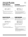
1
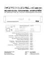
QUAD DUAL CHANNEL AMPLIFIER
Integrated digital system processor amplifier
QDC42.dsp Amplifier Product Description
Specifications and Performance
Front Panel - Features, LCD Display & Menu Key
Rear Panel - Mains, Input & Output Connections
Equipment Rack & Cooling Considerations
Owner’s Manual Terminology
Configuring - Using the Menu Selection System
Configuring - Menu Selection System Screens
Configuring - Parameter Option Values
Programming - DSPB23 Software & DSP Functions
Warranty & Service Information
QDC42.dsp System Block Diagram
Warranty Registration Form
ACOUSTIC TECHNOLOGIES
8-10 Staple Street
Seventeen Mile Rocks
Queensland, 4073 Australia.
Telephone
Fax
Email
Web
Page 1
Page 2
Page 3
Page 4
Page 5
Page 5
Page 6
Page 7
Page 8
Page 9
Page 10
Page 11
Page 12
Page 14
(617) 3376-4122
(617) 3376-5793
[email protected]
www. atprofessional.com.au
2!
QDC42.dsp PRODUCT DESCRIPTION
The Acoustic Technologies QDC42.dsp is an elegantly
designed eight channel audio amplifier featuring extensive
fully integrated digital signal processing systems on board.
The QDC42.dsp is specifically designed to meet the complex
audio amplification requirements often found in sophisticated
installations including:
• Courts of Law
• Public Transportation Terminals - Airports, Bus Terminals
and Railway Stations
• Parliamentary Debating Chambers
• Luxury Home Audio Distribution Systems
• Supermarkets, Shopping Centres etc
• Conference Centres
• Corporate Board Rooms
The QDC42’s amplifiers produce 40 Watts into 4 Ohm Loads,
are highly linear, unconditionally stable and feature extensive
on-chip thermal management & protection circuitry.
The DSPB23 Digital Signal Processing System (DSP) offers
comprehensive audio processing capabilities. Fully featured
Equalisation, Crossover, Gain, Delay and Dynamics Controls
are provided.
A PC based graphical user interface provides a familiar DSP
programming environment.
The QDC42.dsp has no end-user controls. During normal
operation the amplifier’s software operating system is locked,
safeguarding the internal DSPB23 Presets and the amplifiers
Configuration Options.
However: Suitably qualified system engineers can readily
program and configure the QDC42 to the exact requirements
of the overall installation.
The QDC42.dsp is a highly refined system building block,
intended for use in professional audio applications.
Such systems will generally employ multiple amplifiers within
the overall system. With this in mind the QDC42 is
convection cooled, eliminating the noise, maintenance and
reliability issues associated with in-built cooling fans.
For maximum long term reliability, QDC42 amplifiers should
be installed in a professional manner in suitably engineered
equipment racks with appropriate attention to cabling,
electrical supply and air quality, quantity and flow.
The QDC42 is a standard 2 Rack Unit component.
In summary: The QDC42.dsp integrated digital system
processor amplifier offers superb audio performance with
extensive configuration capabilities in a footprint specifically
engineered to meet the complex requirements encountered
within large scale installations.
QDC42.dsp PRODUCT FEATURES
• Four by dual channel high linearity integrated amplifiers
• LCD Display information customizable for the installation
• Comprehensive digital signal processing on each channel
• Configurable Options available to the installer
• Eight programmable DSP Presets per channel
• No Front or Rear Panel Controls
• Electronic Balanced Inputs
• 2RU system oriented building block
• Fully featured PC Software GUI for DSP Programming
• Amplifiers Muted during Power On & Power Off events
• Soft Start and Intelligent Mains Monitoring
• Phoenix Style Input and Output Connections
• Convective Cooling - No fan maintenance and noise free
• Backlit LCD Display for easy system configuration
3!
SPECIFICATIONS - AUDIO AMPLIFIERS
Number of Channels
4 Input Channels - 8 Output Channels
Output Power per Channel (See Note 1)
25 Watts RMS @ 1kHz - 8 Ohms
40 Watts RMS @ 1kHz - 4 Ohms
Frequency Response (See Note 2)
10Hz to 22kHz +0dB , -3dB
Input Sensitivity with DSPB23 Gain of 0dB
0.755 Volts RMS for 25 Watts into 8 Ohm
Input Impedance
16k Ohms Balanced per Channel Pair
Load Impedance
4 Ohms to 16 Ohms
Damping Factor
Greater than 100:1 referenced to 8 Ohms @ 1kHz
Signal to Noise Ratio with DSPB23 Gain of 0dB
Greater than 85dB
Audio Input & Output Connections
Phoenix Style Screw Terminal Plug
Mains Connector & Fuse
IEC Mains Inlet / Fuse Holder. 3 Amp M205 Ceramic Fuse.
RS232 Programming Connector
Female DB9
User Interface
16 Character x 2 Line LCD with blue Backlight,
Recessed push button switch for Menu Selection,
Custom Software for DSP Programming.
Power Requirements
240 Volts AC @ 2 Amps
Dimensions
Standard 19” x 3½” (2RU) Rack Mount
345mm Deep excluding connectors
Weight
11.2 Kgs Net
13.2 Kgs Shipping
SPECIFICATIONS - DSPB23 DIGITAL SIGNAL PROCESSING SYSTEM
Number of DSPB23 Systems
4x Dual Channel Processors
Sample Rate
48kHz 256 x Oversampling
Word Size
24 Bit
Internal Processing
48 Bits double precision floating point
Latency
0.833mSec
Dynamic Range
105dB
FUNCTIONS - DSPB23 DIGITAL SIGNAL PROCESSING SYSTEM
Parametric Equalization
7x PEQ’s / Channel - 2nd Order Response
Parametric Constant Q, Parametric Adaptive Q, Low Shelf, High Shelf,
LP Butterworth, HP Butterworth, Band Pass, Stop Band, All Pass 1, All Pass 2,
Low Pass Q, High Pass Q, IIR Coefficients, Bypass.
Crossover
1x LPF + 1x HPF / Channel - 2nd Order Response
Butterworth, Linkwitz-Riley, Bessel, Bypass
Can be configured to provide 1x LPF or 1x HPF 4th Order.
Gain
Channel Gain, Phase Invert and Mute
Output Delay
0.00mSecs - 3.42mSecs in 0.02mSec increments / Channel
Dynamics
Compression, Limiting and Noise Gate / Channel
Threshold / Limit, Ratio, Knee & Noise Gate Level
User Interface
1. All power measurements conducted according to the IHF202A Standard.
2. Frequency response limits determined by DSPB23 Sample Rate.
Graphical User Interface Software for a PC or Laptop
providing on-screen control panels for all DSPB23 Functions
Acoustic Technologies reserve the right to alter or amend the QDC42.dsp
without prior warning in the interests of product improvement.
4!
LCD DISPLAY - Power On
LCD DISPLAY - Configure & Program
At power-on the QDC42 Status & Configuration Display
(LCD Display) briefly shows the System Software Revision
Number and Issue Date.
When the QDC42 is being configured and programmed the
LCD Display, along with the Menu Key, provides an
interactive Menu Selection System allowing all programmed
parameters of the amplifier’s operation to be selected.
[PRESS] the Menu Key during power-on to increase the
time that the System Software Revision Number and Issue
Date is shown.
LCD BACKLIGHT - Normal / Lock Operation
LCD DISPLAY - Normal / Lock Operation
The QDC42’s LCD Backlight can be configured to be:
During Normal / Lock Operation the QDC42 LCD Display
scrolls through four screens of information.
ON always,
ON for a period of time from 1 - 60 Minutes or
OFF always.
SCREEN 1
The manufacturer’s name.
LCD BACKLIGHT - Programming
Acoustic
When the QDC42 is being configured and programmed the
LCD’s Backlight is always on.
Technologies
SCREEN 2
The product name.
QDC42.dsp
Series Amplifier
SCREEN 3
An optional screen for large installations that displays
custom information such as the location and amplifier
application. Note that this information is embedded at the
time of manufacture. Contact Acoustic Technologies for
additional information on this feature.
MENU SYSTEM SELECTION KEY
During Normal / Lock Operation a [TAP] or [PRESS] on
the Menu System Selection Key (Menu Key) switches the
LCD Backlight on if it were currently off due to the
LCD Backlight Time expiring.
Other than switching the LCD Backlight, there is no
apparent response to the Menu Key having being pressed.
UNLOCKING THE QDC42
However, continuing to [PRESS] the Menu Key for
approximately 10 Seconds unlocks the QDC42, providing
access to the interactive Menu Selection System.
Village Markets
Entry & Food Crt
SCREEN 4
The Preset which has been recalled on each of the four
DSPB23 Systems.
Ch1 P1 | Ch2 P7
Ch3 P6 | Ch4 P2
System Unlocked
Release Key now
5!
MAINS INPUT
INPUT CONNECTIONS
The QDC42 amplifier is supplied with and should only use an
Authority Approved 3 Pin IEC Mains Power Lead with an
Earth Connection.
The QDC42 Balanced Input connections are made via
industry standard “Phoenix Style” multi-pin connectors, which
are supplied with the amplifier.
QDC42 amplifiers are supplied configured for 240 Volt AC
Mains operation.
Always use high quality screened audio cable for input
cabling, connected as shown on the rear of amplifier.
CAUTION:
Under no circumstances should a QDC42 Amplifier be
operated without a suitable Earth Connection which is
provided for important safety reasons.
MAINS FUSE
The QDC42 Mains Fuse is located within the IEC Mains
Connector Socket. For safety always remove the Mains
Power Lead prior to replacing the fuse.
Only use a replacement fuse of the same type and rating as
that which was originally supplied with the amplifier.
TYPE:
RATING:
If an unbalanced output device is being used, connect:
Input +Signal
+ Input
Input Screen
Ground
Amplifier - Input
Ground
Alternatively, consider using a balancing transformer at the
output device end to maximise the rejection of electrical
noise at the amplifier’s input.
Any unused channels should have the + Input & - Input
connected to that channel’s Ground connection.
NOTE:
•
Leave the Output Connections for any unused channels unconnected.
M205 Ceramic
3 Amp
If the Mains Fuse blows repeatedly, investigate the
installation for possible causes such as shorted output wiring
or inappropriate loads. If the Mains Fuse blows repeatedly
with no outputs connected, refer the amplifier to qualified
service personnel.
RS232 DATA PORT
The RS232 Data Part provides bi-directional communication
between the QDC42’s internal DSP and a computer or laptop
running the DSPB23 Programming Software on a Windows /
Intel platform.
The RS232 connection lead is a 9 Pin Female to 9 Pin Male,
wired with straight through connections,
Pin 1 to Pin 1, Pin 2 to Pin 2 and so on.
NOTES:
•
If custom leads are being manufactured, only Pins 2, 3 & 5 are used.
•
If the computer does not have a DB9 Connector consult the computer’s
documentation for alternative pin connections.
For maximum reliability a computer or laptop with an in-built
RS232 Port is preferred. Be particularly cautious of
inexpensive USB-RS232 Converters which tend to be
unreliable at best.
OUTPUT CONNECTIONS
The QDC42 Output Connections are made via industry
standard “Phoenix Style” multi-pin connectors, which are
supplied with the amplifier.
Always use high quality cable for loudspeaker cabling,
connected as shown on the rear of the amplifier.
Ensure that the cable has sufficient conductor area to
minimize ohmic losses in the installation.
CAUTION:
Under no circumstances should the output of one
channel be connected to the output of another channel
or to mains or amplifier ground.
Under no circumstances should a channel +Output be
connected to mains or amplifier ground.
6!
RACK MOUNTING CONSIDERATIONS
The QDC42 is designed as a system oriented building block.
The majority of installations will employ several amplifiers
within the system.
With this in mind the QDC42 is cooled by convection.
Cool air enters through the bottom of the amplifier, flows over
the amplifier heat sinks and exits through the chassis top.
Convection cooling eliminates the maintenance and reliability
issues associated with in-built cooling fans. Furthermore, fan
noise in multi-amplifier installations becomes a real issue.
For maximum long term reliability, QDC42 amplifiers should
be installed in a professional manner in suitably engineered
equipment racks with appropriate attention to cabling,
electrical supply and air quality, quantity and flow.
RACK SPACING BETWEEN AMPLIFIERS
Because the QDC42 is convection cooled, it is mandatory
that a 1RU space be allowed between amplifiers.
In addition a non-circulating airflow through the equipment
rack should be provided. The inflowing air should be filtered
prior to entering the equipment rack.
An environmentally controlled equipment room provides the
ideal operating conditions for all electronic equipment,
resulting in a long-term high reliability installation.
QDC42 TERMINOLOGY
NORMAL / LOCKED OPERATION
Normal / Locked Operation is the normal mode of operation
for the QDC42. The LCD Display shows relevant system
information and the Menu Key does not respond to casual
pushing. Effectively the amplifier’s operating system is
locked, safeguarding the internal DSPB23 Presets and the
amplifiers configuration settings.
STATUS & CONFIGURATION DISPLAY -- LCD DISPLAY
The Status & Configuration Display (LCD Display) shows
relevant system information during Normal / Locked
Operation and is used in conjunction with the Menu Key to
configure and program the QDC42.
MENU SYSTEM SELECTION KEY -- MENU KEY
The Menu System Selection Key (Menu Key) is the push
button switch located behind the QDC42’s front panel.
The Menu Key is used in conjunction with the LCD Display to
configure and program the QDC42.
MENU SELECTION SYSTEM
The Menu Selection System is the QDC42’s internal software
which allows access to the amplifier’s configuration settings
and the DSPB23 Presets.
The installer interacts with the Menu Selection System using
the LCD Display and the Menu Key.
DSPB23 -- DIGITAL SIGNAL PROCESSING SYSTEM
DSPB23 is a dual channel digital signal processing system
incorporated within the QDC42 amplifier, providing
comprehensive audio control capabilities.
There are four DSPB23 Cards within a QDC42 allocated to
Channels 1A&1B, Channels 2A & 2B, Channels 3A & 3B and
Channels 4A & 4B.
CONFIGURE
Configuring a QDC42 means to access, change and save
parameters that control the overall operation of the QDC42.
Configurable Parameters are Channel Preset, LCD Backlight
Time, Autolock and the DSPB23 Card selected for
Programming.
PROGRAM
Programming a QDC42 means to access, change and save
Preset Programs stored within the DSPB23 digital signal
processors using the DSPB23 Software running on a suitable
computer.
TAP the Menu Key
[TAP] the Menu Key means a short push and immediate
release of the Menu Key, typically less than 200mSecs.
[TAP] is used to select from a set of values for a Parameter
Option such as Backlight Time.
PRESS the Menu Key
[PRESS] the Menu Key means to push and hold the Menu
Key, typically longer than 500mSecs.
[PRESS] is used to scroll through the Menu Selection
System and is also used to exit from various operations.
7!
USING THE MENU SELECTION SYSTEM
The QDC42 Menu Selection System is accessed by a
[PRESS] of the Menu Key. The Menu System scrolls the
available Configuration Options on the LCD Display in the
order shown on the following page of this manual.
When the required Configuration Option is showing on the
LCD Display, release the Menu Key to select that
Configuration Option for change.
CHANGING AN OPTION VALUE
After a Configuration Option has been accessed for change,
the QDC42 prompts the operator to select a new value for
the selected Configuration Option or to Exit to the Menu
Selection System.
Using Backlight Time as an example:
The LCD Display will alternate between the two screens
shown below which show that the current Backlight Time is
10 minutes.
The LCD Display is prompting for an operator action.
When the desired value is showing on the LCD Display,
[ PRESS ] the Menu Key for 3 Seconds to store the selected
value and return to the Menu Selection System.
As the Menu Key is pressed the LCD Display confirms the
store operation.
Press Key 3 Sec
Exit Backlight
Tap to Advance
Backlight 10 min
Alternating Screens
Backlight 10 min
Press to Exit
Press Key 2 Sec
Exit Backlight
Press Key 1 Sec
Exit Backlight
A [TAP] on the Menu Key will advance the Backlight Time to
the next available value, which is a Backlight Time of
20 Mins.
System Menu
Backlight 20 min
Tap to Advance
Repeatedly tapping the Menu Key advances the Backlight
Time through all available values, after which they repeat.
Backlight 40 min
Tap to Advance
Backlight 60 min
Tap to Advance
Press to select
8!
MENU SELECTION SYSTEM SCREENS
System Menu
Release Key for
Press to select
Channel 4 Preset
The Menu Selection System is waiting for the Operator to
[PRESS] the Menu Key
Releasing the Menu Key now will allow the DSPB23 Preset
selected for Channel 4A & Channel 4B to be changed.
Entering
Release Key for
System Menu
Backlight Time
The operator has pressed the Menu Key
The Menu Selection System is about to be accessed.
Releasing the Menu Key now will allow the Backlight Time to
be changed.
Release Key for
Release Key for
System Lock/Exit
Autolock Mode
Releasing the Menu Key now will lock the QDC42, exit the
Menu Selection System & start the LCD Backlight Timer
Releasing the Menu Key now will allow the Autolock Mode to
be changed.
Release Key for
Release Key for
Channel 1 Preset
DSPB23 PrgmMode
Releasing the Menu Key now will allow the DSPB23 Preset
selected for Channel 1A & Channel 1B to be changed.
Releasing the Menu Key now will allow the selection of the
DSPB23 Card which will be accessed by the RS232 Data
Port.
Release Key for
Channel 2 Preset
Menu Ended
Release Key now
Releasing the Menu Key now will allow the DSPB23 Preset
selected for Channel 2A & Channel 2B to be changed.
Release Key for
Channel 3 Preset
Releasing the Menu Key now will allow the DSPB23 Preset
selected for Channel 3A & Channel 3B to be changed.
The end of the Menu Selection System has been reached.
Release the Menu Key to return to the start of the Menu
Selection System.
9!
CHANNEL PRESET VALUES
AUTOLOCK MODE
The QDC42’s internal DSPB23 digital signal processing
systems stores eight Presets per DSP Card.
The Autolock Configuration Option, when selected to On,
allows the QDC42 to automatically revert to Normal / Locked
Operation from Configure & Program Mode if there has been
no Menu Key activity for greater then 60 minutes.
The Channel Preset Configuration Option allows the
selection of which of the eight DSPB23 Preset is recalled.
Chan 1
Autolock On
Preset 1
Tap to Advance
Tap to Advance
NOTES
NOTES
•
•
At Power-On the QDC42 always starts in Normal /Locked Operation
•
Autolock does NOT monitor activity on the RS232 Data Port
If Autolock is invoked during a DSPB23 data transfer, the connection will
be dropped with possible DSPB23 Preset Data corruption.
Therefore: If there is to be prolonged DSPB23 programming, it would be
desirable to switch Autolock to Off while programming and switch it back
On at the completion of programming.
•
The QDC42 features four totally independent DSPB23 digital signal
processing cards allocated to Channels 1A/1B, Channels 2A/2B
and so on.
Programming the DSPB23’s is accomplished using the DSPB23
Programming Software running on a suitable computer.
Once programmed, there is no further need for a computer connection
BACKLIGHT TIME VALUES
DSPB23 PROGRAM MODE
The QDC42 provides control of the LCD Display’s Backlight
during Normal / Locked Operation.
Programming the QDC42’s digital signal processing system
requires that a connection between the RS232 Data Port and
a DSPB23 Card be established.
The Backlight Time Configuration Option allows the selection
of the Backlight On Time.
DSPB23 Program Mode selects which of the four DSPB23
Cards is connected to the RS232 Data Port.
Backlight 10 min
Channels 1A & 1B
Tap to Advance
Tap to Advance
The allowable Backlight Times are:
The allowable DSPB23 Program Modes are:
1, 2, 5, 10, 20, 40, 60 Minutes
ON always and
OFF always.
Channels 1A & 1B, Channels 2A & 2B,
NOTES
NOTES
•
The LCD Backlight is always on during Configuration
•
•
During Normal / Locked Operation a [PRESS] or [TAP] on the Menu
Key switches the LCD Backlight on and resets the Backlight Timer.
Do not change the selected DSPB23 Card during RS232 data transfer.
This is to avoid the connection being dropped and possibility of DSPB23
Preset Data corruption.
•
During Normal / Locked Operation the RS232 Data Port is not connected to
any DSPB23 Card.
•
Autolock does NOT monitor activity on the RS232 Data Port
If Autolock is invoked during a DSPB23 data transfer, the connection will
be dropped with possible DSPB23 Preset Data corruption.
Therefore: If there is to be prolonged DSPB23 programming, it would be
desirable to switch Autolock to Off while programming and switch it back
On at the completion of programming.
Channels 3A & 3B, Channels 4A & 4B
:!
DSPB23 COMMS PORT CONNECTION
The DSPB23 communicates with the PC or Laptop via an
RS232 Serial Data Link.
DSPB23 MAIN SCREEN
Communication is established when the software is run or by
selecting the [CONNECT] Button in the Menu Panel.
Offline programming allows Presets to be defined without a
connection to the QDC42.
The DSPB23 digital signal processing system provides
comprehensive audio processing. The PC based graphical
user interface provides a familiar programming environment
for the installation professional.
The RS232 Connection Lead is a 9 Pin Male to 9 Pin
Female, wired with straight through connections,
Pin 1 to Pin 1, Pin 2 to Pin 2 and so on.
The Main Screen allows access to each of the functional
processing blocks. A Menu Panel allows communication with
the QDC42’s hardware, disk based file operations and
several ancillary functions.
•
If custom leads are being manufactured, only Pins 2, 3 & 5 are used.
•
If the computer does not have a DB9 Connector consult the computer’s
documentation for alternative pin connections.
NOTES:
The Main Screen allows the naming of the Channel’s Input
and Outputs and provides a text Comment Box suitable for
documentation purposes.
For maximum reliability a computer or laptop with an in-built
RS232 Port is preferred. Be particularly cautious of
inexpensive USB-RS232 Converters which tend to be
unreliable at best.
DSPB23 PARAMETRIC EQUALIZATION
DSPB23 CROSSOVER
nd
The DSPB23 provides 7x 2 Order PEQ Filters / Channel
with 13x filter topologies available for each PEQ, selected
from a drop down selector box. The available filter types are:
Parametric Constant Q
Shelf Low 6dB
Low Pass Butterworth
Band Pass
All Pass 1
Low Pass Q
IIR Coefficients
Parametric Adaptive Q
Shelf High 6dB
High Pass Butterworth
Stop Band
All Pass 2
High Pass Q
Bypass
Filter adjustments are made with value sliders, text boxes
and scroll buttons. The combined response of each
channel’s equalization, both magnitude and phase, is
graphically displayed.
The DSPB23 provides 2x 2nd Order Crossover Filters /
Channel.
The Crossover can be configured to provide either a 2nd
Order LPF / HPF Crossover, or the filters can be combined to
provide a single 4th Order LP or HP Filter section.
The available filter types are:
Butterworth
Bessel
Linkwitz-Riley
Bypass
Crossover adjustments are made with a drop down selector
box, text boxes and scroll buttons. The combined response
of each channel’s Crossover, both magnitude and phase, is
graphically displayed.
21!
DSPB23 OUTPUT GAIN LEVELS
DSPB23 OUTPUT DELAY
The DSPB23 provides Gain Control, Polarity Invert and Mute
for each channel.
The DSPB23 provides a continuously variable Delay time for
each channel.
Channel Gain is variable over a 36dB range, adjustable in
0.1dB increments via a value slider or text box.
The Delay time is variable from 0.00mSecs to 3.40mSecs in
0.02mSec increments via a value slider or text box.
Buttons are used to select the Polarity Invert and Channel
Mute functions.
Alternatively, the DSPB23 allows the relative distance
between acoustic centres to be entered. Clicking the
[Auto Align] button computes the required Delay to physically
align the acoustic centres.
Temperature compensation for Delay time is also provided
DSPB23 DYNAMICS PROCESSOR
DSPB23 FINAL RESPONSE
The DSPB23 provides highly flexible Dynamics control by
offering a Limiter or Compressor for each output channel.
Adjustable parameters are:
The Final Response Panel graphically displays the combined
response of the entire DSPB23 Preset. Both magnitude and
phase response plots for each channel are provided.
Threshold
Compression Ratio
Attack (dB/Sec)
Hold Time (mSecs)
In addition the DSPB23 Software allows the direct import of
the SPL and Phase response of each of the loudspeaker
system’s components, allowing the response of the entire
processing, amplifier and loudspeaker system to be
accurately modelled.
Knee
Noise Gate Level
Release (dB/Sec)
A graphic display of the Dynamics transfer function is shown.
Loudspeaker Box Parameters can be entered to the
Dynamics Section and a warning is provided if it is possible
to exceed the loudspeaker ratings using the current
Dynamics Settings.
The QDC42 Linear Gain is 18.
22!
WARRANTY REGISTRATION
SERVICE AFTER THE WARRANTY PERIOD
When you receive the QDC42 amplifier, complete the
Warranty Page (the last page of this manual) and return it to
Acoustic Technologies within 14 days of the purchase date.
Acoustic Technologies offers a quick service facility for
repairs outside the warranty period.
Alternatively, the QDC42 Warranty Registration can be
completed online at:
Charges are kept to the minimum possible for parts and
labour. It is strongly recommended that the QDC42 amplifier
be repaired by the manufacturer or authorised repair facility.
www.atprofessional.com.au/products/warrantyregister.html
WARRANTY PERIOD
Acoustic Technologies provides a comprehensive 1 Year
Warranty on all parts and labour for the QDC42 Amplifier to
the original owner from the purchase date.
PLEASE NOTE:
Acoustic Technologies reserves the right to ascertain the
reason for the amplifier's failure, and if attributed to operator
negligence or improper operating conditions, reserves the
right to refuse warranty service.
Any transportation costs incurred are to be met by the
customer claiming warranty service.
PLEASE NOTE:
Acoustic Technologies reserves the right to alter or amend
the QDC42 amplifier without prior warning, in the interests of
product improvement.
F
E
D
C
1
2
MAINS
VOLTAGE
MONITOR
RS232 DATA
CONTROL
LOGIC
INPUT 1
INPUT 2
INPUT 3
G
+
-
G
+
-
G
+
-
G
+
-
3
RS232
DATA
INPUT 4
B
3
DSPB23
Card 4
DSPB23
Card 3
DSPB23
Card 2
DSPB23
Card 1
4
5
AMPLIFIER
MUTE
MENU SELECTION SYSTEM SOFTWARE
QDC42 SYSTEM CONTROL LOGIC
PRESET
SELECT
2
6
MENU
KEY
LCD BACKLIGHT
LCD DISPLAY
7
8
Checked
Approved
6
7
QDC42 BLOCK DIAGRAM
Drawn R. Faint
Scale NTS
Sheet 1 of 1
A
AT-A3-344
8
Revision
acoustic technologies
OUTPUT 4B
OUTPUT 4A
OUTPUT 3B
OUTPUT 3A
OUTPUT 2B
OUTPUT 2A
OUTPUT 1B
OUTPUT 1A
A 10.11.2008
A
1
Original Issue
RS232
INPUT
F
E
D
C
B
A
24!
THIS PAGE INTENTIONALLY BLANK
Warranty Registration
Acoustic Technologies
PO Box 107
Sumner Park
Queensland 4074
Australia
NAME / PROJECT : ..............................................................................
ADDRESS
: ..............................................................................
: ..............................................................................
: ..............................................................................
PURCHASED FROM
DEALER
: ..............................................................................
ADDRESS
: ..............................................................................
: ..............................................................................
: ..............................................................................
AMPLIFIER MODEL
: QDC42.dsp
SERIAL NUMBER
: ........................
DATE of PURCHASE
: ......./......./........
The QDC42.dsp Warranty Registration can be completed online at the following address:
http://www.atprofessional.com.au/products/warrantyregister.html