1
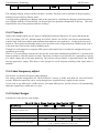
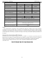
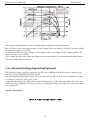
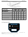
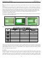
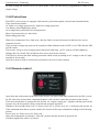
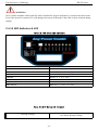
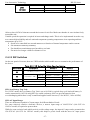
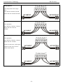
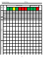
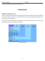
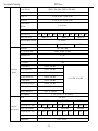
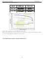
Line-Interactive Technology HP-PV Series HP-PV Series Pure Sine Wave Inverter For All Home & Office Appliances User’s Manual Version 1.0 Utility + Inverter + Charger + Transfer SW + Solar Power + AGS All in One -1- Line-Interactive Technology HP-PV Series Table of Contents 1. Important Safety Information.........................................................................................................................3 1-1. General Safety Precautions.........................................................................................................................3 1-2. Precautions When Working with Batteries.................................................................................................3 2. Introduction.................................................................................................................................................... 4 2.1. General Information.................................................................................................................................... 4 2.2. Application.................................................................................................................................................. 4 2.3. Features....................................................................................................................................................... 8 2.4 Electrical Performance................................................................................................................................. 8 2.4.1 Inverter............................................................................................................................................... 8 2.4.2 AC Charger.........................................................................................................................................8 2.4.3 Transfer.............................................................................................................................................11 2.4.4 Auto frequency adjust...................................................................................................................... 12 2.4.5 Solar Charger....................................................................................................................................12 2.4.6 Automatic Voltage Regulation.........................................................................................................13 2.4.7 Power Saver..................................................................................................................................... 15 2.4.8 Protections........................................................................................................................................16 2.4.9 Remote control................................................................................................................................. 16 2.4.10 LED Indicator & LCD................................................................................................................... 17 2.4.11 Audible Alarm................................................................................................................................18 2.4.12 FAN Operation...............................................................................................................................18 2.4.13 DIP Switches..................................................................................................................................18 2.4.14 Output Socket.................................................................................................................................19 2.4.15 Other features................................................................................................................................. 19 3 Installation.....................................................................................................................................................21 3.1 Location...............................................................................................................................................21 3.2 DC Wiring recommendation............................................................................................................... 21 3.3 AC Wiring...........................................................................................................................................21 4 Troubleshooting Guide..................................................................................................................................25 5 Warranty........................................................................................................................................................27 6 Order Information......................................................................................................................................... 28 Appendix 1....................................................................................................................................................... 28 -2- Line-Interactive Technology HP-PV Series 1. Important Safety Information WARNING! This manual contains important instructions for all HP Inverter/Charger models that shall be followed during installation and maintenance of the inverter. 1-1. General Safety Precautions 1. Before installing and using the HP Inverter/Charger, read all instructions and cautionary markings on the HP Inverter /Charger and all appropriate sections of this guide. Be sure to read all instructions and cautionary markings for any equipment attached to this unit. 2. This unit is designed for indoor use only. Do not expose the HP Inverter/Charger to rain, snow, or spray. 3. To reduce risk of fire hazard, do not cover or obstruct the ventilation openings. Do not install the HP Inverter/Charger in a zero-clearance compartment. Overheating may result. 4. Use only attachments recommended or sold by the manufacturer. Doing otherwise may result in a risk of fire, electric shock, or injury to persons. 5. To avoid a risk of fire and electric shock, make sure that existing wiring is in good condition and that wire is not undersized. Do not operate the HP Inverter/Charger with damaged or substandard wiring. 6. Do not operate the HP Inverter/Charger if it has received a sharp blow, been dropped, or otherwise damaged in any way. If the HP Inverter/Charger is damaged, see the Warranty section. 7. Do not disassemble the HP Inverter/Charger. It contains no user-serviceable parts. See Warranty for instructions on obtaining service. Attempting to service the HP Inverter/Charger yourself may result in a risk of electrical shock or fire. Internal capacitors remain charged after all power is disconnected. 8. The HP Inverter contains more than one live circuit (batteries and AC line). Power may be present at more than one source. To reduce the risk of electrical shock, disconnect both AC and DC power from the HP Inverter/Charger before attempting any maintenance or cleaning or working on any circuits connected to the HP Inverter/Charger. Turning off controls will not reduce this risk. 9. Use insulated tools to reduce the chance of short-circuits when installing or working with the inverter, the batteries, or PV array. 1-2. Precautions When Working with Batteries 1. Make sure the area around the battery is well ventilated. 2. Never smoke or allow a spark or flame near the engine or batteries. 3. Use caution to reduce the risk or dropping a metal tool on the battery. It could spark or short circuit the battery or other electrical parts and could cause an explosion. 4. Remove all metal items, like rings, brace lets, and watches when working with lead-acid batteries. Lead-acid batteries produce a short circuit current high enough to weld metal to skin, causing a severe burn. 5. Have someone within range of your voice or close enough to come to your aid when you work near a lead-acid battery. 6. Have plenty of fresh water and soap near by in case battery acid contacts skin, clothing, or eyes. 7. Wear complete eye protection and clothing protection. Avoid touching your eyes while working near -3- Line-Interactive Technology HP-PV Series batteries. 8. If battery acid contacts skin or clot hing, wash immediately with soap and water. If acid enters your eye, immediately flood it with running cold water for at least twenty minutes and get medical attention immediately. 9. If you need to remove a battery, always remove the grounded terminal from the battery first. Make sure all accessories are off so you don’t cause a spark. 10. Always use identical types of batteries. 11. Never install old or untested batteries. Check each battery’s date code or label to ensure age and type. 12. Batteries are temperature sensitive. For optimum performance, the should be installed in a stable temperature environment. 13. Always recycle old batteries. Contact your local recycling center for proper disposal information. -4- Line-Interactive Technology HP-PV Series 2. Introduction 2-1. General Information Thank you for purchasing the HP Series Inverter/Charger. HP-PV Series Pure Sine Wave Inverter is a combination of an inverter, charger, solar power and Auto-transfer switch into one complete system . It is packed with unique features and it is one of the most advanced inverter/chargers in the market today. The inverter features an AC pass-through circuit, powering your home appliances from utility or generator power while charging the battery. When utility power fails, the battery backup system keeps your appliances powered until utility power is restored. Internal protection circuits prevent over-discharge of the batteries by shutting down the inverter when a low battery condition occurs. When utility or generator power is restored, the inverter transfers to the AC source and recharges the batteries. Accessories allow the HP-PV series to also serve as a central hub of a renewable energy system. Set the HP-PV Series inverter to battery priority mode, designates the inverter-preferred UPS configuration. In this configuration, the load power in normally provided by the inverter. However, if the inverter output is interrupted, an internal transfer switch automatically transfers the load from the inverter to commercial AC power. The transfer time between inverter and line is short(6ms typical), and such transfers are normally not detected by even highly sensitive loads. Upon restoration of inverter power, the inverter will transfer back to inverter power. On the line priority mode, when utility AC power cuts off(or falls out of acceptable range), the transfer relay is de-energized and the load is automatically transferred to the Inverter output. Once the qualified AC utility is restored, the relay is energized and the load is automatically reconnected to AC utility. It features power factor corrected, sophisticated multi-stage charging and pure sine wave output with unprecedentedly high surge capability to meet demanding power needs of inductive loads without endangering the equipment. HP-PV Series Inverter is equipped with a powerful charger of up to 120Amp (depending on Model). The overload capacity is 300% of continuous output for up to 20 seconds to reliably support tools and equipment longer Another important feature is that the inverter can be easily customized to Battery priority via a DIP switch, this helps to extract maximum power from battery in renewable energy systems. Thus, the HP-PV Series Pure Sine Wave Inverter is suitable for Renewable energy system, Utility, RV, Marine and Emergency appliances. To get the most out of the power inverter, it must be installed, used and maintained properly. Please read the instructions in this manual before installing and operating. 2-2. Application Power tools–circular saws, drills, grinders, sanders, buffers, weed and hedge trimmers, air compressors. Office equipment – computers, printers, monitors, facsimile machines, scanners. -5- Line-Interactive Technology HP-PV Series Household items – vacuum cleaners, fans, fluorescent and incandescent lights, shavers, sewing machines. Kitchen appliances – coffee makers, blenders, ice markers, toasters. Industrial equipment – metal halide lamp, high – pressure sodium lamp. Home entertainment electronics – television, VCRs, video games, stereos, musical instruments, satellite equipment. 2.3 Features Smart Remote Control (RMT) Battery Temperature Sensor (BTS) Automatic Generator Starting (AGS) Support Solar Panel with MPPT Function Designed to Operate under Harsh Environment DC Start & Automatic Self-Diagnostic Function Compatible with Both Linear & Non-Linear Load Easy to Install & Easy to Operate & Easy to Solve Low DC Voltage Supports Home & Office Appliances Powerful Charge Rate Up to 120Amp, Selectable From 0%-100% High Efficiency Design & “Power Saving Mode” to Conserve Energy Battery Priority Mode, Designates the Inverter-Preferred UPS Configuration 13 Vdc Battery Recover Point, Dedicated for Renewable Energy Systems 8 pre Set Battery Type Selector plus De-sulphation for Totally Flat Batteries 4-step Intelligent Battery Charging, PFC (Power Factor Correction) for Charger 8 ms Typical Transfer Time Between Utility & Battery, Guarantees Power Continuity 15s Delay Before Transfer when AC Resumes, Protection for Load when Used with Generator 2.4 Electrical Performance 2.4.1 Inverter Topology The HP-PV inverter/charger is built according to the following topology. Inverter: Full Bridge Topology. AC Charger: Isolate Boost Topology Solar Charger: MPPT PV Controller Because of high efficiency Mosfets and 16bit, 4.9MHz microprocessor and heavy transformers, it outputs PURE SINE WAVE AC with an average THD of 10% (Min5%, Max 15%) depending of load connected and battery voltage. The peak efficiency of HP-PV series is 88%. Overload Capacity The HP-PV series inverters have different overload capacities, making it ideal to handle demanding loads. 1 For 110%<Load<125%(±10%), no audible alarm in 14 minutes, beeps 0.5s every 1s in the 15th minute, and Fault(Turn off) after the 15th minute. 2 For 125%<Load<150%(±10%), beeps 0.5s every 1s and Fault(Turn off) after the 1 minute. 3 For 300%≧Load>150%(±10%), beeps 0.5s every 1s and Fault(Turn off) after 20s. -6- Line-Interactive Technology HP-PV Series 2.4.2 AC Charger HP Series is equipped with an active PFC (Power Factor Corrected) multistage battery charger. The PFC feature is used to control the amount of power used to charge the batteries in order to obtain a power factor as close as possible to 1. Unlike other inverters whose max charging current decreases according to the input AC voltage, HP-PV series charger is able to output max current as long as input AC voltage is in the range of 164-243VAC (95-127VAC for 120V model), and AC freq is in the range of 48-54Hz(58-64Hz for 60Hz model). The HP-PV series inverter is with a strong charging current of 120Amp (for 4KW,12V), and the max charge current can be adjusted from 0%-100% via a liner switch at the right of the battery type selector. This will be helpful if you are using our powerful charger on a small capacity battery bank. Fortunately, the liner switch can effectively reduce the max charging current to 20% of its peak. Choosing “0” in the battery type selector will disable charging function. There are mainly 3 stages: Bulk Charging: This is the initial stage of charging. While Bulk Charging, the charger supplies the battery with controlled constant current. The charger will remain in Bulk charge until the Absorption charge voltage (determined by the Battery Type selection) is achieved. Software timer will measure the time from A/C start until the battery charger reaches 0.3V below the boost voltage, then take this time asT0 and T0×2 = T1. Absorb Charging: This is the second charging stage and begins after the absorb voltage has been reached. Absorb Charging provides the batteries with a constant voltage and reduces the DC charging current in order to maintain the absorb voltage setting. In this period, the inverter will start a T1 timer; the charger will keep the boost voltage in Boost CV mode until the T1 timer has run out. Then drop the voltage down to the float voltage. The timer has a minimum time of 1 hour and a maximum time of 12 hours. Float Charging: The third charging stage occurs at the end of the Absorb Charging time. While Float charging, the charge voltage is reduced to the fl oat charge voltage (determined by the Battery Type selection*). In this stage, the batteries are kept fully charged and ready if needed by the inverter. If the A/C is reconnected or the battery voltage drops below 12Vdc/24Vdc/48Vdc, the charger will reset the cycle above. If the charge maintains the float state for 10 days, the charger will deliberately reset the cycle to protect the battery. Table 2.5.1 Battery Charging Processes -7- Line-Interactive Technology HP-PV Series Table 2.5.2 Battery Type Selector Switch Setting Description Fast Mode / VDC 0 Float Mode / VDC Charger Off 1 Gel USA 14.0 13.7 2 AGM 1 14.1 13.4 3 LiFePO4 14.6 13.7 4 Sealed Lead Acid 14.4 13.6 5 Gel EURO 14.4 13.8 6 Open Lead Acid 14.8 13.3 7 Calcium 15.1 13.6 8 De-sulphation 15.5 (4 Hours then Off) For 12Vdc Mode Series (*2 for 24Vdc Mode ; *4 for 48Vdc Mode) De-sulphation The de-sulphation cycle on switch position 8 is marked in red because this is a very dangerous setting if you do not know what you are doing. Before ever attempting to use this cycle you must clearly understand what it does and when and how you would use it. What causes sulphation? This can occur with infrequent use of the batteries(nor), or if the batteries have been left discharged so low that they will not accept a charge. This cycle is a very high voltage charge cycle designed to try to break down the sulphated crust that is preventing the plates taking a charge and thus allow the plates to clean up and so accept charge once again. Charging depleted batteries The HP-PV series inverter allows start up and through power with depleted batteries. For 12VDC model, after the battery voltage goes below 10V, if the switch is still (and always) kept in "ON" position, the inverter is always connected with battery, and the battery voltage does not drop below 2V, the inverter will be able to charge the battery once qualified AC inputs are present. Before the battery voltage goes below 9VDC, the charging can be activated when the switch is turned to “Off”, then to “ON”. When the voltage goes below 9VDC, and you accidently turn the switch to OFF or disconnect the inverter from battery, the inverter will not be able to charge the battery once again, because the CPU loses memory during this process. Tabel 2.5.3 AC Charging Current for HP model Model AC Charger Current Model Battery Voltage Watt Max 1.000 12 Vdc 45 ± 5 Amp ~ 24 Vdc 25 ± 5 Amp 1.500 48 Vdc 3.000 Watt Max 12 Vdc 70 ± 5 Amp 24 Vdc 35 ± 5 Amp 15 ± 5 Amp 48 Vdc 20 ± 5 Amp 12 Vdc 90 ± 5 Amp 12 Vdc 120 ± 5 Amp 24 Vdc 50 ± 5 Amp 24 Vdc 65 ± 5 Amp 48 Vdc 30 ± 5 Amp 48 Vdc 40 ± 5 Amp 24 Vdc 80 ± 5 Amp 24 Vdc 90 ± 5 Amp 48 Vdc 60 ± 5 Amp 48 Vdc 100 ± 5 Amp 2.000 4.000 5.000 8.000 AC Charger Current Battery Voltage 6.000 48 Vdc 50 ± 5 Amp 24 Vdc 120 ± 5 Amp 10.000 -8- Line-Interactive Technology 48 Vdc HP-PV Series 80 ± 5 Amp 12.000 48 Vdc 120 ± 5 Amp The charging capacity will go to peak in around 3 seconds. This may cause a generator to drop frequency, making inverter transfer to battery mode. It is suggested to gradually put charging load on the generator by switching the charging switch from min to max, together with the 15s switch delay, our inverter gives the generator enough time to spin up. This will depend on the size of the generator and rate of charge. 2.4.3 Transfer While in the Standby Mode, the AC input is continually monitored. Whenever AC power falls below the VAC Trip voltage (154 VAC, default setting for 230VAC,90VAC for 120VAC), the inverter automatically transfers back to the Invert Mode with minimum interruption to your appliances - as long as the inverter is turned on. The transfer from Standby mode to Inverter mode occurs in approximately 8 milliseconds. And it is the same time from Inverter mode to Standby mode. Though it is not designed as a computer UPS system, this transfer time is usually fast enough to keep your equipment powered up. There is a 15-second delay from the time the inverter senses that continuously qualified AC is present at the input terminals to when the transfer is made. This delay is built in to provide time for a generator to spin-up to a stable voltage and avoid relay chattering. The inverter will not transfer to generator until it has locked onto the generator’s output. This delay is also designed to avoid frequent switching when input utility is unstable. 2.4.4 Auto frequency adjust The inverter is with Auto Frequency adjust function. The factory default configuration for 220/230/240VAC inverter is 50Hz, and 60Hz for 100/110/120VAC inverter. While the output freq can be easily changed once a qualified freq is applied to the inverter. If you want to get 60Hz from a 50Hz inverter, just input 60Hz power, and the inverter will automatically adjust the output freq to 60Hz and vice versa. 2.4.5 Solar Charger Listed below is the spec for solar charger Table 2.5.4 Solar Charge Electrical Specification @ 25℃ Rated Voltage 12Vdc 24Vdc Rated Charge Current 40/60Amp (Includes Load Current) Load Ccurrent Input Voltage Range Max. PV Open Circuit Array Voltage Overload Protection (DC load) 48Vdc 40Amp 15Amp 15-30Vdc 30-55Vdc 60-100Vdc 35Vdc 60Vdc 105Vdc 2.0 * I(Rated)>5s;1.5 * I(Rated) >20s 1.25 * I(Rated) Temperature Controlled -9- Line-Interactive Technology HP-PV Series Typical Idle Consumption At idle < 10mA Bulk Charge 14.6Vdc 29.2Vdc 58.4Vdc Floating Charge 13.4Vdc 26.8Vdc 53.6Vdc Equalization Charge 14.0Vdc 28.0Vdc 58.0Vdc Over Charge Disconnect 14.8Vdc 29.6Vdc 59.2Vdc Over Charge Recovery 13.6Vdc 27.2Vdc 54.4Vdc Over dDischarge Disconnect 10.8Vdc 21.6Vdc 43.2Vdc Over Discharge Reconnect 12.3Vdc 24.6Vdc 49.6Vdc Temperature Compensation -13.2mV/℃ -26.4mV/℃ -52.8mV/℃ Lead Acid Battery Settings Adjustable NiCad Battery Settings Adjustable Low Voltage Reconnect 12.0-14.0Vdc 24.0-28.0Vdc 48.0-56.0Vdc Low Voltage Disconnect 10.5-12.5Vdc 21.0-25.0Vdc 42.0-50.0Vdc Ambient Temperature 0-40℃ (Full load) Altitude 40-60℃ (De-rating) Operating 5000m, Non-Operating 16000m Protection Class IP21 BTS (Optional ) Battery Temperature Sensor① Remote Battery Temperature Sensor for Increased Charging Precision Terminal Size (Fine/Single Wire) #8 AWG NOTE: ①The optional battery temperature sensor automatically adjusts the charging process of the controller according to the type of battery that is selected by user through battery type selector. With the battery temperature sensor installed, the controller will increase or decrease the battery charging voltage depending on the temperature of the battery to optimize the charge to the battery and maintain optional performance of the battery. Maximum Power Point Tracking (MPPT) Function Maximum Power Point Tracking, frequently referred to as MPPT, is an electronic system that operates the Photovoltaic (PV) modules in a manner that allows the modules to produce all the power they are capable of. The PV-seeker Charge controller is a microprocessor-based system designed to implement the MPPT. And it can increase charge current up to 30% or more compared to traditional charge controllers (See Table 2.5.4). Table 2.5.5 Current, Power Vs. Voltage Characteristics - 10 - Line-Interactive Technology HP-PV Series The Charge controller built in is with 12/24/48V battery voltage auto detecting function. For 12/24VDC inverter, the output voltage of solar charger will be accordingly 12/24VDC, and the qualified DC input volt range is 15v-55VDC. For 48VDC inverter, the output voltage of solar charger will be accordingly 48VDC, and the qualified DC input volt range is 55v-110VDC. If the voltage falls out of this range, the charger will not work properly. Special attention should be paid to this when configuring the solar array. 2.4.6 Automatic Voltage Regulation(Optional) The automatic voltage regulation function is for full series of HPPure Sine Wave Inverter/ Charger except split phase models including HP1000W~6000W. Instead of simply bypassing the input AC to power the loads, the HP-SV series inverter stabilizes the input AC voltage to a range of 230V/120V±10%. Connected with batteries, the HPS Series inverter will function as a UPS with max transfer time of 10 ms. With all the unique features our inverter provides, it will bring you long-term trouble free operation beyond your expectation. Function Introduction Table 2.5.5 Input Voltage Transfer Points - 11 - Line-Interactive Technology HP-PV Series HPS-PV Series HPS-PV Function (Optional) LV (NA/JPN) HV (INTL) 0-160 0-300 Acceptable Input Voltage Range (Vac) Nominal Input Voltages (Vac) 100 110 120 220 230 240 (A) Line low loss N/W (On battery) 75/65 84/72 92/78 168/143 176/150 183/156 (B) Line Low comeback N/W (On Boost) 80/70 89/77 97/83 178/153 186/160 193/166 (C) Line 2nd boost threshold (On Boost) ** ** ** ** ** ** (D) Line 2nd boost comeback (On Normal) ** ** ** ** ** ** (E) Line 1st boost threshold (On Boost) 90 99 108 198 207 216 (F) Line 1st boost comeback (On Normal) 93 103 112 205 215 225 (G) Line buck comeback (On Normal) 106 118 128 235 246 256 (H) Line buck threshold (On Buck) 110 121 132 242 253 264 (I) Line high comeback (On Buck) 115 127 139 253 266 278 (J) Line high loss (On Battery) 120 132 144 263 276 288 2.4.7 Power Saver Mode There are 3 different working status for HP inverter: “Power Saver Auto” 、“Power Saver Off” and “Power Off”. When power switch is in “Unit Off” position, the inverter is powered off. - 12 - Line-Interactive Technology HP-PV Series When power switch is turned to either of “Power Saver Auto” or “Power Saver Off”, the inverter is powered on. Power saver function is designed to conserve battery power when AC power is not or rarely required by the loads. In this mode, the inverter pulses the AC output looking for an AC load (i.e., electrical appliance). Whenever an AC load (greater than 25 watts) is turned on, the inverter recognizes the need for power and automatically starts inverting and output goes to full voltage. When there is no load (or less than 25 watts) detected, the inverter automatically goes back into search mode to minimize energy consumption from the battery bank. In “Power saver on” mode, the inverter will draw power mainly in sensing moments, thus the idle consumption is significantly reduced. The inverter is factory defaulted to detect load for 250ms every 30 seconds. This cycle can be customized to 3 seconds turn SW3 on the DIP switch. Power saver on Power saver off Power saver on (Load detected) Note: The minimum power of load to take inverter out of sleep mode (Power Saver On) is 25 Watts. Table 2.5.6 HP Series Idle Power Consumption Model Power Saver Off Power Saver Auto Idle 3Secs(Max) Stand-By Mode 1.000W 15W 7.5W 6.6W 1.500W 18W 7.5W 6.6W 2.000W 30W 11.5W 6.6W 3.000W 60W 20.0W 6.6W 4.000W 70W 20.0W 6.6W 5.000W 80W 25.0W 6.6W 6.000W 90W 25.0W 6.6W 8.000W 120W 30.0W 6.6W 10.000W 150W 35.0W 6.6W 12.000W 180W 35.0W 6.6W When in the search sense mode, the green power LED will blink and the inverter will make a ticking sound. At full output voltage, the green power LED will light steadily and the inverter will make a steady humming sound. When the inverter is used as an “uninterruptible” power supply the search sense mode or “Power Saver On” function should be defeated. Exceptions Some devices when scanned by the load sensor cannot be detected. Small fluorescent lights are the most common example. (Try altering the plug polarity by turning the plug over.) Some computers and sophisticated electronics have power supplies that do not present a load until line voltage is available. When this occurs, each unit waits for the other to begin. To drive these loads either a small companion load must - 13 - Line-Interactive Technology HP-PV Series be used to bring the inverter out of its search mode, or the inverter may be programmed to remain at full output voltage. 2.4.8 Protections The HP-PV series inverter is equipped with extensive protections against various harsh situations/faults. These protections include: AC Input over voltage protection/AC Input low voltage protection Low battery alarm/High battery alarm Over temperature protection/Over load protection Short Circuit protection (1s after fault) Back feeding protection When Over temperature /Over load occur, after the fault is cleared, the master switch has to be reset to restart the inverter. The Low batter voltage trip point can be customized from defaulted value 10VDC to 10.5VDC thru the SW1 on DIP switch. The inverter will go to Over temp protection when heat sink temp. ≥105ºC, and go to Fault (shutdown Output) after 30 seconds. The switch has to be reset to activate the inverter. The HP series Inverter has back feeding protection which avoids presenting an AC voltage on the AC input terminal in Invert mode. After the reason for fault is cleared, the inverter has to be reset to start working. 2.4.9 Remote control Apart from the switch panel on the front of the inverter, an extra switch panel connected to the RJ11 port at the DC side of the inverter thru a standard telephone cable can also control the operation of the inverter. If an extra switch panel is connected to the inverter via “remote control port”, together with the panel on the inverter case, the two panels will be connected and operated in parallel. Whichever first switches from “Off” to “Power saver off” or “Power saver on”, it will power the inverter on. If the commands from the two panels conflict, the inverter will accept command according to the following priority: Power saver on> Power saver off> Power off Only when both panels are turned to “Unit Off” position will the inverter be powered off. The Max length of the cable is 10 meters. - 14 - Line-Interactive Technology HP-PV Series WARNING Never cut the telephone cable when the cable is attached to inverter and battery is connected to the inverter. Even if the inverter is turned off. It will damage the remote PCB inside if the cable is short circuited during cutting. 2.4.10 LED Indicator & LCD Table 2.5.7 HP Series LED Indicators LINE MODE GREEN LED lit in AC Mode INVERTER MODE GREEN LED lit in Inverter Mode FAST CHARGE YELLOW LED lit in Fast Charging Mode FLOAT CHARGE GREEN LED lit in Float Charging Mode ALARM MODE RED LED lit in Error State OVER TEMP TRIP RED LED lit in Over Temperature OVER LOAD TRIP RED LED lit in Over Load POWER SAVER ON GREEN LED lit in Power Saver Mode Table 2.5.8 HP Series LCD Indicator 1 Greeting message 2 AC Status & Input Voltage - 15 - Line-Interactive Technology HP-PV Series “AC: abnormal” will be displayed when AC input is not qualified. 4 Output Current( in percentage) 3 Output Voltage/Frequency and Battery voltage 2.4.11 Audible Alarm Table 2.5.9 HP Series Audible Alarm Spec Battery Voltage Low Inverter green LED lit, and the buzzer beeps 0.5s every 5s. Battery Voltage High Inverter green LED lit, and the buzzer beeps 0.5s every 1s and Fault after 60s. (1)110%<load<125%(±10%), No audible alarm in 14 minutes, th Invert Mode Over-Load Beeps 0.5s every 1s in 15 minute and Fault after 15 minutes; (2)125% <load<150%(±10%), Beeps 0.5s every 1s and Fault after 60s; (3)Load>150%(±10%), Beeps 0.5s every 1s and Fault after 20s; Over Temperature Heatsink temp. ≥105ºC, Over temp red LED Lighting, beeps 0.5s every 1s; 2.4.12 FAN Operation For 1-3KW, there is one multiple controlled DC fan which starts to work according to the following logic. For 4-12KW, there is two multiple controlled DC fan and one AC fan. The DC fan will work in the same way as the one on 1-3KW, while the AC fan will work once there is AC output from the inverter. So when the inverter is in power saver mode, the AC fan will work from time to time in response to the pulse sent by the inverter in power saver mode. The Operation of the DC fan at the DC terminal side is controlled by the following logic (Refer to Table 2.5.10): Table 2.5.10 HP Series Fan Operation Logic Condition HEAT SINK TEMPERATURE CHARGER CURRENT Enter condition Leave condition Speed T ≤ 60℃ T > 65℃ OFF 65℃≤ T <85 ℃ T ≤ 60℃ / T ≥ 85℃ 50% T > 85℃ T ≤ 80℃ 100% I ≤ 15% I ≥ 20% OFF 20%< I ≤ 50% I ≤ 15% / I ≥ 50% 50% I > 50% I ≤ 40% 100% - 16 - Line-Interactive Technology HP-PV Series LOAD% (INV MODE) Load < 30% Load ≥ 30% OFF 30% ≤ Load < 50% Load ≤ 20% / Load ≥ 50% 50% Load ≥ 50% Load ≤ 40% 100% Allow at least 30CM of clearance around the inverter for air flow. Make sure that the air can circulate freely around the unit. Variable speed fan operation is required in invert and charge mode. This is to be implemented in such a way as to ensure high reliability and safe unit and component operating temperatures in an operating ambient temperature up to 50°C. Speed to be controlled in a smooth manner as a function of internal temperature and/or current. Fan should not start/stop suddenly. Fan should run at minimum speed needed to cool unit. Fan noise level target <60db at a distance of 1m. 2.4.13 DIP Switches On the rear panel of inverter, there are 5 DIP switches which enable users to customize the performance of the device. Table 2.5.11 HP Series Dip Switch Function Setting DIP Switch NO. Switch Function SW1 Low Battery Trip Volt Position: 0 Position: 1 10.0Vdc 10.5Vdc *2 for 24Vdc, *4 for 48Vdc SW2 230Vac HV 184-253Vac / (176-276Vac) 154-253Vac / (150-276Vac) 120Vac LV 100-135Vac / (92-144Vac) 90-135Vac / (78-144Vac) AC Input Range / (AVR) SW3 Power Saver Auto Setting Detect Load Per 5Secs Night Charge Function SW4 O/P Frequency Setting 50Hz 60Hz SW5 Solar/AC Priority Setting Utility Priority Solar Priority SW1:Low Battery Trip Volt: For 12VDC model, the Low Battery Trip Volt is set at 10.0Vdc by typical deep cycle lead acid battery. It can be customized to 10.5Vdc using SW1 for sealed car battery, this is to prevent batteries from over-discharging while there is only a small load applied on the inverter.(*2 for 24VDC, *4 for 48VDC) SW2:AC Input Range: There are different acceptable AC input ranges for different kinds of loads. For some relatively sensitive electronic devices, a narrow input range of 184-253VAC (100-135V for 120VAC model) is required to protect them. While for some resistive loads which work in a wide voltage range, the input AC range can be customized to 154-253VAC (90-135V for 120VAC model), this helps to power loads with the most AC input power - 17 - Line-Interactive Technology HP-PV Series without frequent switches to the battery bank. Power Saver Auto Setting : The inverter is factory defaulted to detect load for 250ms in every 5 seconds. This cycle can be customized to 3 seconds thru the SW3 on the DIP switch. Solar/AC Priority: Our inverter is designed with AC priority by default. This means, when AC input is present, the battery will be charged first, and the inverter will transfer the input AC to power the load. Only when the AC input is stable for a continuous period of 15 days, the inverter will start a battery inverting cycle to protect the battery. After 1 cycle normal charging and ac through put will be restored. The AC Priority and Battery Priority switch is SW5. When you choose battery priority, the inverter will inverting from battery despite the AC input. Only when the battery voltage is reaches low voltage alarm point(10.5V for 12V), the inverter transfers to AC Input, charges battery, and switches back to battery when battery is charged full. This function is mainly for wind/solar systems taking utility power as back up. 2.4.14 Output Socket The inverter is either equipped with a dual GFCI socket (rated at 30Amps) or an universal socket (rated at 10Amps) for more convenient wiring. 2.4.15 Other features Battery voltage recover start After low battery voltage shut off (10V for 12V model/20V for 24V model/40V for 48V model), the inverter is able to restore operation after the battery voltage recovers to 13Vdc/26Vdc/52Vdc (with power switch still in the “On” position). This function helps to save the users extra labor to reactivate the inverter when the low battery voltage returns to an acceptable range in the renewable energy systems. The built in battery charger will automatically reactivate as soon as city/generator ac has been stable for 15 seconds. WARNING Never leave the loads unattended, some loads (like a Heater) may cause accident in such cases. It is better to shut everything down after low voltage trip than to leave your load on, due to the risk of fire. Auto Gen Start The inverter can be customized to start up a generator when battery voltage goes low. When the inverter goes to low battery alarm, it can send a signal to start a generator, and turn the generator off after battery charging is finished. The auto gen start feature will only work with generators designed to work with this feature. There is an open/closed relay that will short circuit the positive and negative cable from a generator. The input DC voltage can vary, but the Max current the relay can carry is 16Amp. Conformal Coating - 18 - Line-Interactive Technology HP-PV Series EYEN entire line of HP-PV inverters have been processed with a conformal coating on the PCB making it water, rust, and dust resistant. - 19 - Line-Interactive Technology HP-PV Series 3 Installation 3.1 Location Follow all the local regulations to install the inverter. Please install the equipment in a location that is Dry, Clean, Cool and that has good ventilation. Working temperature: ‐10℃‐40℃ Storage temperature: ‐40‐70℃ Relative Humidity: 0%‐95%,non-condensing Cooling: Forced air 3.2 DC Wiring recommendation It is suggested the battery bank be kept as close as possible to the inverter. The following able is a suggested wiring option for 1 meter DC cable. Please find the following minimum wire size. In case of DC cable longer than 1m, please increase the cross section of cable to reduce the loss. Wire Gage /Min Model Watt Wire Gage /Min Model Battery Voltage Battery Voltage 0~1.0m 1.0~5.0m Watt 0~1.0m 1.0~5.0m 12 Vdc 60mm² 75mm² 24 Vdc 30mm² 45mm² 1.000 12 Vdc 30mm² 40mm² ~ 24 Vdc 15mm² 20mm² 1.500 48 Vdc 10mm² 15mm² 48 Vdc 15mm² 25mm² 12 Vdc 90mm² 120mm² 12 Vdc 120mm² 150mm² 24 Vdc 45mm² 60mm² 24 Vdc 60mm² 75mm² 48 Vdc 25mm² 30mm² 48 Vdc 30mm² 40mm² 24 Vdc 75mm² 95mm² 24 Vdc 90mm² 120mm² 48 Vdc 45mm² 60mm² 3.000 5.000 2.000 4.000 6.000 48 Vdc 40mm² 50mm² 24 Vdc 120mm² 150mm² 10.000 48 Vdc 75mm² 95mm² 48 Vdc 60mm² 75mm² 12.000 48 Vdc 90mm² 120mm² 8.000 Please note that if there is a problem obtaining for example 90mm²cable, use 2*50mm²or 3*35mm². One cable is always best , but cable is simply copper and all you require is the copper, so it does not matter if it is one cable or 10 cables as long as the square area adds up. Performance of any product can be improved by thicker cable and shorter runs, so if in doubt round up and keep the length as short as possible. 3.3 AC Wiring We recommend using 10-5Awg wire to connect to the ac terminal block. There are 3 different ways of connecting to the terminal block depending on the model. All the wirings are CE compliant, Call our tech support if you are not sure about how to wire any part of your inverter. - 20 - Line-Interactive Technology HP-PV Series Wiring Option 1 230V single phase/120V single phase Input: Hot line+Neutral+Ground Output: Hot line+Neutral+Ground Wiring Option 2 230V split phase Input: Hot line+ Hot line +Ground Output: Hot line+ Hot line +Neutral Wiring Option 3 ` 230V split phase Input: Hot line+ Hot line +Ground Output: Hot line +Neutral Remark: In such cases, each output hotline can only carry a max of half the rated capacity. - 21 - Line-Interactive Technology HP-PV Series 4 Troubleshooting Guide Troubleshooting contains information about how to troubleshoot possible error conditions while using the HP Series Inverter & Charger. The following chart is designed to help you quickly pinpoint the most common inverter failures. Indicator and Buzzer - 22 - Line-Interactive Technology HP-PV Series Indicator On Front Panel Status Item Utility Inverter Fast Float Power On On Charge Charge C.C √ × √ × Line C.V √ × √, Blink Mode Float √ × Standby √ Inverter Inverter On Mode Mode Buzzer Over-Temp Over-Load Power Save CHARGER INVERTER Trip Trip On ON ON × × × × √ × × × × × × × × √ × × × × √ × × × × √ × × × × × × × × × × × × × × × √ × × × × × × × √ × × Power Saver × × × × × × × √ × × × × Battery Low × √ × × √ × × × × √ √ Battery High × √ × × √ × × × × √ √ Overload On Inverter Indicator On Remote Module Inverter Mode Over-Temp On Alarm ALARM × √ × × √ × √ × × √ √ × × √ √ × × × √ √ √ × √ × √ √ × × √ × √ Over Charge √ × √ × √ × × × √ × √ Fan Lock × × × × × × × × × × × Battery High × √ × × × × × × × √ × × × × × × × √ × × × × Output Short × × × × √ × √ × × × √ Over-Temp × × × × × √ × × × × × Line Mode Fault Inverter Mode Mode Overload Beep 0.5s every 1s “Audible alarm” √ Over-Temp On every 5s Refer to × Inverter Mode Beep 0.5s - 23 - Beep 0.5s every 1s Beep 0.5s every 1s Beep 0.5s every 1s Beep continuous Beep continuous Beep continuous Beep continuous Beep Line-Interactive Technology HP-PV Series continuous Fault Mode Over Charge Back Feed Short × × √ × × × × × √ × × × × × × × × × × × × × Symptom Inverter will not turn on during initial power up. Possible Cause Batteries are not connected, loose battery-side connections. Recommended Solution Check the batteries and cable connections. Check DC fuse and breaker. Low battery voltage. Inverter has been manually transitioned to OFF mode. Low battery. Charge the battery. Press the switch to Power saver on or Power saver off position. Check the condition of the batteries and recharge if possible. AC voltage has dropped out-of-tolerance Charger controls are improperly set. Check the AC voltage for proper voltage and frequency. Refer to the section on adjusting the “Charger Rate”. Low AC input voltage. Source qualified AC power.. Check all DC /AC connections. Charger turns OFF while charging from a generator. Loose battery or AC input connections. High AC input voltages from the generator. Sensitive loads turn off Inverter's Low voltage trip voltage No AC output voltage and no indicator lights ON. AC output voltage is low and the inverter turns loads OFF in a short time. Charger is inoperative and unit will not accept AC. Charger is supplying a lower charge rate. Load the generator down with a heavy load. Turn the generator output voltage down. Choose narrow AC voltage in the - 24 - Beep continuous Beep continuous Line-Interactive Technology temporarily when transferring between grid and inverting. Noise from Transformer/case* HP-PV Series may be too low to sustain certain loads. Applying specific loads such as hair drier DIP switch, or Install a UPS if possible. Remove the loads *The reason for the noise from transformer and/or case When in inverter mode sometimes the transformer and/or case of the inverter may vibrate and make noise. If the noise comes from transformer: According to the characteristics of our inverter, mainly there is one type of load which most likely may cause rattles of transformer. That is half wave load: A load that uses only half cycle of the power (see figure 1). This tends to cause an imbalance of the magnetic field of the transformer, reducing its rated working freq from 20KHz to maybe 15KHz (it varies according to different loads). In such a case the frequency of noise falls exactly into the range (200Hz-20KHz) that human ears can hear. The most common load of such kind is a hair drier. If the noise comes from the case: Normally when loaded with inductive loads, the magnetic field generated by the transformer keeps attracting or releasing the steel case at a specific freq, this may also cause noise. Reducing the load power or using an inverter with bigger capacity will normally solve this problem. The noise will not do any harm to the inverter or the loads. Figure 1 Half Cycle Load Waveform 5 Warranty We offer a 1 year limited warranty. The following cases are not covered under warranty. 1 DC polarity reverse. The inverter is designed without DC polarity reverse protection. A polarity reverse may severely damage the inverter. 2 Wrong AC wiring 3 Operating in a wet environment. - 25 - Line-Interactive Technology HP-PV Series 4 Operating with an undersized generator or generator with unqualified wave form. 6 Ordering Information Model Identification and Numbering Conventions The HP Inverter is identified by the model/serial number labels. The Serial Number can be located on the mounting rail or inside the top cover. Model Number labels may be located on the bottom side of the front cover or possibly inside the front cover. All the necessary information is provided on the label such as AC output voltage, power and frequency (punch holes). The inverter also has a letter designator followed by 4-6 digits (depending on revision). The model number describes the type of inverter, the output specifications, the required battery voltage and the output voltage and frequency. Figure 6-1 Product Identification - 26 - Line-Interactive Technology HP-PV Series Appendix 1 Electrical Specifications Model 1.0KW 1.5KW 2.0KW 3.0KW 4.0KW 5.0KW 6.0KW 8.0KW 10.0KW 12.0KW Continuous Output Power 1.0KW 1.5KW 2.0KW 3.0KW 4.0KW 5.0KW 6.0KW 8.0KW 10.0KW 12.0KW Surge Rating(20ms) 3.0KW 4.5KW 6.0KW 9.0KW 12.0KW 15.0KW 18.0KW 24.0KW 30.0KW 36.0KW Output Waveform Pure Sine wave/Same as input(Bypass Mode) Nominal Efficiency >88%(Peak) Line Mode Efficiency Inverter Output >95% Power Factor 0.9-1.0 Nominal Output Voltage rms 100-110-120Vac / 220-230-240Vac Output Voltage Regulation ±10% RMS Output Frequency 50Hz ± 0.3Hz/60Hz ± 0.3Hz Short Circuit Protection Yes( 1sec after fault ) Typical transfer Time 10ms(Max) THD DC Input < 10% Nominal Input Voltage 12.0Vdc / 24.0Vdc / 48.0Vdc Minimum Start Voltage 10.0Vdc / 10.5Vdc for 12Vdc Mode Low Battery Alarm 10.5Vdc / 11.0Vdc for 12Vdc Mode Low Battery Trip 10.0Vdc / 10.5Vdc for 12Vdc Mode High Voltage Alarm 16.0Vdc for 12Vdc Mode Low Battery voltage recover 15.5Vdc for 12Vdc Mode Idle Consumption-Search Mode Charger Start 10A 15A Bypass & Protection 20A 20A 30A 40A 40A *2 for 24Vdc, *4 for 48Vdc; 15.7Vdc for 12Vdc Mode Yes(Refer to the table ) Variances in Charging Voltage & S.D Voltage Base on the Battery Temperature. Input Voltage Waveform Nominal Voltage 30A 10-15.7Vdc for 12Vdc Mode Battery Temperature Sensor (Optional) 20A 1/3 Rating Power (Refer to Table 2.5.3) Over Charge Protection S.D. BTS *2 for 24Vdc, *4 for 48Vdc; Depends on battery type (Refer to Table 2.5.2) Max Charge Power Rate Battery Initial Voltage for 48.0Vdc < 25 W when Power Saver On.(Refer to Table ) Output Voltage Charger Breaker Rating 24.0Vdc / 48.0Vdc Sine wave (Grid or Generator) 110Vac 120Vac - 27 - 220Vac 230Vac 230Vac 40A Line-Interactive Technology HP-PV Series Max Input AC Voltage 150VAC For 120Vac LV Mode;300VAC For 230Vac HV Mode; Nominal Input Frequency 50Hz or 60Hz Low Freq Trip 47±0.3Hz for 50Hz, 57±0.3Hz for 60Hz High Freq Trip 55±0.3Hz for 50Hz, 65±0.3Hz for 60Hz Overload protection Circuit Breaker (SMPS load) Output Short circuit protection Bypass breaker rating Circuit Breaker 10A Transfer switch rating 15A 20A 30A 30Amp 80Amp 15-30Vdc / 30-55Vdc / 55-100Vdc Rated Charge Current 40 ~ 60A Rated Output Current 15A < 10mA Bulk Charge(Default) 14.5Vdc for 12Vdc Mode Floating Charge(Default) 13.5Vdc for 12Vdc Mode Equalization Charge(Default) 14.0Vdc for 12Vdc Mode Over Charge Disconnection 14.8Vdc for 12Vdc Mode Over Charge Recovery 13.6Vdc for 12Vdc Mode Over Discharge Disconnection 10.8Vdc for 12Vdc Mode Over Discharge Reconnection 12.3Vdc for 12Vdc Mode Temperature Compensation ( *2 for 24Vdc, *4 for 48Vdc) -13.2mV/℃ for 12Vdc Mode Ambient Temperature 0 ~ 40℃(Full load) Mounting 40 ~ 60℃(Derating) Wall Mount Inverter Dimensions(L*W*H) 388*415*200mm 21+2.5 Shipping Dimensions(L*W*H) Shipping Weight(Solar Chg)KG 63A 80Amp for UL 40Amp Self Consumption Specifications 63A 12Vdc / 24Vdc / 48Vdc Solar Input Voltage Range Inverter Weight(Solar Chg)KG 50A 40Amp for UL Rated Voltage Mechanical 40A Yes (Optional) Max bypass current (Optional) 40A 30Amp for UL & TUV Bypass without battery connected Solar Charger 40A 22+2.5 23+2.5 488*415*200mm 27+2.5 38+2.5 550*520*310mm 23+2.5 24+2.5 25+2.5 Display 48+2.5 588*415*200mm 49+2.5 650*520*310mm 29+2.5 40+2.5 50+2.5 3 Years (Optional) - 28 - 66+2.5 70+2.5 750*520*310mm 51+2.5 Status LEDs / Status LEDs+LCD Standard Warranty 60+2.5 62+2.5 68+2.5 72+2.5 Line-Interactive Technology HP-PV Series Appendix 2 Battery Temperature Compensation Condition Charger Mode Inverter Mode INV/CHG Status Transfer Point CHG On >>>CHG Off BTS ≥ 50℃ CHG Off >>> CHG On BTS ≤ 40℃ S.D Point + 0.5Vdc 40℃ ≤ BTS ≤ 50℃ Over Temp Fault BTS ≥ 50℃ Fast Charge Voltage Float Charge Voltage Battery Low Alarm Voltage Battery Low S.D Voltage Default output voltage for Float and Absorption are at 25℃. Reduce Float voltage follows Float voltage and Raised Absorption voltage follows Absorption voltage. In a adjust mode temperature compensation does not apply. Note: Specifications subject to change without notice. - 29 -


![[User manual (English) - v1.6] 1.7 MB](http://vs1.manualzilla.com/store/data/005855357_1-51a3ddd110ebec5d1eef2b5791ba3868-150x150.png)