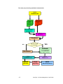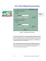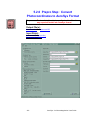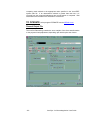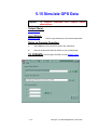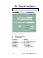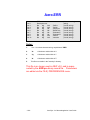
1
User Guide
Version 3.0
AeroSys Consulting
1401 Portland Avenue
Saint Paul, MN 55104
USA
Voice/FAX: 651-645-5320
[email protected]
http://www.bigfoot.com/~AeroSys
About this Manual
Over view
Below is a brief overview of the manual.
Chapter 1: Introduction
Chapter 2: Getting Started
provides a HOW-TO guide to
setup a project and successfully
process your data starting with
pre-processing and ending with
the bundle adjustment.
Chapter 3: Airborne GPS Blocks
provides a HOW-TO guide to
use airborne GPS data with the
AERO bundle adjustment.
Chapter 4: The Basics
shows the IN’s and OUT’s about
key AeroSys program dialog
windows and menu functions.
Chapter 5: AeroSys Programs
provides detailed information on
all system programs.
Appendix A: Data File Formats
provides detailed information
about all data formats that are
used by the AeroSys programs.
Appendix B: Photocoordinate Formats
-2-
AeroSys v3.0 Aerotriangulation User Guide
TABLE OF CONTENTS
About this Manual
2
1.0 INTRODUCTION
9
1.1 Technical Support
11
1.2 Software Installation
12
1.3 AeroSys Directories
13
1.4 License Policy
14
1.5 Warrantee
14
2.0 GETTING STARTED
15
2.1 Collect AT data
17
2.3 Setup a Project
20
2.4 Translate Photocoordinate Data
25
2.5 Bundle Adjustment Pre-Processing
26
2.5 Aero Bundle Adjustment
30
3.0 AIRBORNE GPS BLOCKS
32
4.0 THE BASICS
35
4.1 AeroSys Main Menu
35
4.2 AeroSys Preferences
40
4.3 Photocoordinate Format Translation
46
4.4 Pre-processing
47
4.5 Aero Bundle Adjustment
4.5.1 Aero (*.AER) Data Editor
4.5.2 Aero Configuration
4.5.3 Close Range Pre-processing
4.5.4 Running the Bundle Adjustment
4.5.5 Post-Adjustment Quick Summary
49
50
53
54
55
56
-3-
AeroSys v3.0 Aerotriangulation User Guide
5.0 AEROSYS PROGRAMS
57
5.1 Aero
5.1.1 Options Dialog
5.1.1.1 Termination Criterion
5.1.1.2 Degrees of Freedom
5.1.1.3 Statistical Levels
5.1.1.4 Work Directory
5.1.1.5 General
5.1.1.6 Atmospheric
5.1.1.7 Trace
5.1.1.8 Self-Calibration
5.1.1.8.1 Self-Calibration | Mode
5.1.1.8.2 Self-Calibration | Physical Parameters
5.1.1.8.3 Self-Calibration | Empirical Film Deformation
5.1.1.8.4 Self-Calibration | 3rd Order Film Deformation
5.1.1.8.5 Self-Calibration | Affinity
5.1.2 Close-Range Preprocessing
5.1.2.1 Space Resection
5.1.2.2 Space Intersection
5.1.3 Adjust Menu
57
58
59
60
61
62
63
64
65
66
66
67
68
69
70
71
72
72
73
5.2 Pre-processing (Prepro) Auto-Sequence
5.2.0 Prepro Step: Convert Photocoordinates to AeroSys Format
5.2.1 Prepro Step: Split
5.2.3 Prepro Step: Refine
5.2.4 Prepro Step: Combine
5.2.5 Prepro Step: RELative ORieNtation
5.2.6 Prepro Step: StripForm
5.2.7 Prepro Step: BlockForm
5.2.8 Prepro Step: Estimate Ground Coordinates
5.2.9 Prepro Step: Resect
5.2.11 Prepro Step: Merge
5.2.12 Prepro Step: Image Rays
81
82
84
86
87
88
89
90
91
93
95
96
5.3 AddGPS
97
5.4 Atmospheric Corrections
98
5.5 Camera Calibration
99
5.6 Compare
102
5.7 Cut & Paste
103
5.8 Distortion
105
5.9 DLT
106
5.10 GPS Antenna Offsets
107
5.11 Image Rays
108
5.12 Flip-Flop Photo Order
109
-4-
AeroSys v3.0 Aerotriangulation User Guide
5.13 Coordinate Rotations
110
5.14 Simulate
111
5.15 Simulate GPS Data
113
5.16 Space Intersection
114
5.17 Space Resection
115
5.18 Stereopair Orientation
116
5.19 Coordinate Transformations
117
5.20 Stereoplotter Setup
119
5.21 General Translations
120
APPENDIX A:
121
DATA FILE FORMATS
121
BaseName.3DR
121
BaseName.3DT
122
BaseName.ADJ
123
BaseName.AER
Aero Data Block No.1
Aero Data Block No.2
Aero Data Block No.3
Aero Data Block No.4
Aero Data Block No.5
Aero Data Block No.6
124
126
127
128
129
130
131
BaseName.APB
132
BaseName.ATM
133
BaseName.BLD
134
BaseName.BLK
135
BaseName.C&P
136
BaseName.CAL
137
BaseName.CAM
138
BaseName.CAO
139
BaseName.CMP
140
-5-
AeroSys v3.0 Aerotriangulation User Guide
BaseName.CP2
141
BaseName.CRL
142
BaseName.CTL
143
BaseName.DLT
144
BaseName.DOF
146
BaseName.ERR
147
BaseName.EST
148
BaseName.GCP
149
BaseName.GPS
150
BaseName.IDX
151
BaseName.IIS
152
BaseName.INF
153
BaseName.MEA, CRL & TSF
154
BaseName.OFF
155
BaseName.OLD
156
BaseName.ORN
157
BaseName.PHC
158
BaseName.REF
160
BaseName.REL
162
BaseName.RES
164
BaseName.RLD
165
BaseName.RST & .ORN
166
BaseName.SIM
167
BaseName.SPC
168
BaseName.SPI
169
BaseName.SPL
170
BaseName.SPO
171
BaseName.SPR
172
-6-
AeroSys v3.0 Aerotriangulation User Guide
BaseName.STP & .BLK
173
BaseName.SVY
175
BaseName.TSF
176
BaseName.TXT
177
BaseName.UPD
178
BaseName.XYP or "Rwell".CP
179
BaseName.XYZ & .ADJ
180
StripFile.TXT
181
Aero.CFG
182
Aero.DFL
184
Aero.DIR
185
Aero.ERR
186
Aero.FMT
187
Aero.PAR
188
Aero.PFX
191
Aero.PID
192
APPENDIX B: PHOTOCOORDINATE FORMATS
193
ABC (*.tri, raw plate coordinates)
193
ADAM Technology (*.pco, refined coords)
194
ALBANY (*.mea)
195
ATP
196
BINGO
197
BLUH
198
Intergraph Image Station
199
IMA
200
IIS Alpha 2000
201
Kern DSR (*.mea)
202
-7-
AeroSys v3.0 Aerotriangulation User Guide
Kern (*.pla , plate coords)
203
PAT-B
204
RWEL (*.CP raw plate coords)
205
WIS-DOT
206
Zeiss
207
-8-
AeroSys v3.0 Aerotriangulation User Guide
1.0 Introduction
Welc ome
Welcome to AeroSys v3.0 for WinNT/95/98. The new and improved (32-bit)
AeroSys is a fast, easy-to-use, windows-based aerotriangulation system
designed specifically for GIS professionals, photogrammetrists and
mapping specialists. AeroSys offers an integrated set of menu driven
(GUI-based) programs that provides tools to complete aerial triangulation
process, including:
•
•
•
•
•
•
•
•
•
•
•
•
Pro c es si ng
To ols
P
Phhoottooccoooorrddiinnaattee
FFoorrm
maattss
Project Setup
Camera Data Base Editor
Image Coordinate Format Translations
Image Coordinate Refinement
Independent Model Relative Orientation
Strip and Block Formation in Model Space
Polynomial Strip Adjustment
3D Rigid Body Coordinate Transformation
Space (Photo) Resection
Space (Point) Intersection
Pre-Adjustment Image Rays Checking
Bundle Adjustment with Self-Calibration
AeroSys supports photocoordinate translations for the following formats:
ABC
ADAM Technology
ATP
BINGO
BLUH
Intergraph Image Station
IMA (ASCII)
I2S Alpha 200
JFK
Kern DSR (*.mea & *.pla)
PAT-B
Rwel (*.cp)
WIS-DOT
ZEISS
Other program features include:
• Data Manipulation and Inspection
• Aero (*.AER) Data File Editor
• Data Simulation Generator
• Close-Range Camera Calibration
• 2D & 3D Coordinate Transformations
• Error & Data Checking and other Utilities
• Project Information Retrieval
• Support for Kinematic Airborne GPS
-9-
AeroSys v3.0 Aerotriangulation User Guide
Fe atur es
Easy Data Setup
Data files for AeroSys programs consist entirely of FREE-FORMAT ASCII (text)
files that can be easily prepared or modified using most window’s-based text
editors. AeroSys automatically creates most of its own data files for fast, efficient
progression from start to finish throughout the system. Input data text files are
structured as free format and freely viewable.
Simple Operation
AeroSys’s user-friendly programs are entirely menu driven at the click of a
mouse. The intuitive graphical user interface (GUI) environment allows the user
to easily repeat the usual RUN-ANALYZE-EDIT sequence quickly and efficiently.
System Requirements
AeroSys runs on most Pentium class or 586-compatible computers configured
with at least 64 MB RAM (128 MB recommended) running under WinNT/98/95.
Comprehensive Documentation
An easy-to-read, totally on-line users manual is provided along with sample data
files. The "Getting Started" chapter gives the user a step by step introduction.
Great Versatility
AeroSys bundle adjustment can be used to solve networks of aerial blocks as
well as close-range designs. It can simultaneously employ multiple cameras
within a block, has self-calibration capability, can incorporate surveying
observations and kinematic airborne GPS coordinates.
Technological Advantage
Mapping companies can move their operations off of older UNIX-based
computers and on to state-of-the-art PC workstations. For small companies
needing aerotriangulation services, they can avoid the high cost of UNIX
workstations and have in-house capabilities at an affordable price. AeroSys
programs are compiled into optimized 32-bit exe’s for top performance.
Good
Val ue
AeroSys v3.0 is the best valued AT package on the market!!
INTROduction & PROduction packages include CD-ROM, Marx Crypto Box,
User's manual in HTML & PDF formats, sample data sets, 30-day money back
guarantee of satisfaction, 60 day free software configuration support from the
date of purchase. Purchase provides license for use of the program system on a
stand-alone PC workstation at a single site.
- 10 -
AeroSys v3.0 Aerotriangulation User Guide
1.1 Technical Support
AeroSys Consulting offers technical support to registered customers.
If you have questions, comments or suggestions, you can contact us by
telephone, fax or e-mail.
Program bug fixes/updates will be posted to the AeroSys Software web site.
Tel ep ho ne
Fa x
E- mai l
You can personally contact us before 9:00 am or after 6:00 pm (CDT), or send a
FAX anytime at:
Voice/Fax (651) 645-5320
We can also be contacted through the Internet.
Please e-mail inquires to
H ome Page
Po st al
Ad dr es s
Re mem ber
[email protected]
http://www.bigfoot.com/~AeroSys
By mail, you can write us at:
Dr. Matt H. Stevens
AeroSys Consulting
1401 Portland Ave
Saint Paul, MN 55104
USA
In your request for resolving a problem, be sure to include:
1. Attach your zipped data files to your email.
2. A clearly written description of the problem.
3. The product version and ASW crypto box serial number.
- 11 -
AeroSys v3.0 Aerotriangulation User Guide
1.2 Software Installation
Tip:
INTROduction and
PROduction packages only.
The free demo does not require a
Marx Crypto Box, but in this case
the Aero Bundle Adjustment is
limited to a maximum of four
photos and 20 object points..
(1) Connect the Marx Crypto Box software security key directly to your
workstation’s main parallel port, i.e. LPT1: If you have a printer cable,
connect this to the Marx Key.
(2) Log on to your computer as “Administrator” or as a user that has full
administrator privileges.
(3) Place the AeroSys CD in your computer’s CD-ROM drive. If auto-sensing is
enabled, the installation program will automatically launch itself from the
disk. Follow the installation menu’s to load AeroSys onto your computer’s
“C” drive under C:\AeroSys\asw30.
The very last step in the installation will load and register the Marx Crypto
box drivers into your winNT/95/98 system directory. If this step fails, you can
perform this step again after the installation by executing the regCBN.exe
which is located in the C:\AeroSys\asw30\cBox\win32 directory. To do this,
bring up an Explorer Window, traverse to the above directory and double
click on the regCBN.exe icon in the list.
(4) Re-boot your computer.
(5)
Launch AeroSys by clicking on its icon in the windows “Start” menu on your
computer’s desktop.
- 12 -
AeroSys v3.0 Aerotriangulation User Guide
1.3 AeroSys Directories
AeroSys AT package is installed onto your computer’s C: drive, under
C:\AeroSys\asw30. The following sub-directories are also created:
; Top Level directory
C:\AeroSys\
Asw30\
; ASW30 program EXE’s and DLL’s
; Marx Crypto Box Drivers and install scripts
Bin
cBox\
win32
win3x
win95
winNT
; Sample data sets and projects
Data\
Demo
Intro
Pro
Doc
Etc
Formats
Help
Info
Log
Sys
Tmp
- 13 -
; AeroSys documentation files
; miscellaneous files
; various photocoordinate formats supported
; AeroSys help files: WINHELP, HTML & PDF
; Project information file bin
; Log file bin
; AeroSys system files
; Temp directory
AeroSys v3.0 Aerotriangulation User Guide
1.4 License Policy
Both United States copyright law and international treaty provisions protect this
software. Only registered users of this software are authorized to make archival
copies of the software for the sole purpose of backing-up the software and
protecting their investment from loss.
This is a single workstation/site license, which entitles a registered user of
AeroSys to freely install multiple copies of this software on more than one
computer, provided that copies are not transported off the building site or
premises. Additional Marx Crypto box software security keys can be purchased
to activate these installations.
All rights not specifically granted in this statement
are reserved by Dr. Matt H. Stevens.
1.5 Warrantee
The entire and exclusive liability of this Warranty shall be limited to the
replacement of defective CD-ROM media and shall not include or extend to any
claim for or right to recover any other damages, including but not limited to, loss
of profit, data or use of the software, or special, incidental or consequential
damages or other similar claims. All other warranties, expressed or implied, are
disclaimed.
- 14 -
AeroSys v3.0 Aerotriangulation User Guide
2.0 Getting Started
This section of the manual will lead the user through the steps needed to process
their AT data. The steps are grouped into the following:
(0) Setup AeroSys user preferences. See 4.2 AeroSys Preferences
(1) Collect all AT (photocoordinates) data files
directory, e.g., d:\AT_Projects\Job_No1.
into a uniquely name data
(2) Generate a *.CTL ground control data file. AeroSys has several translation
functions that the user may find useful to do this.
(3) Setup a project file using the AeroSys GUI-base dialog windows. During this
step the user may need to update the camera database with additional
camera data that correspond to the given AT data.
(4) Translate the photocoordinate data into AeroSys format, if necessary.
(5) Perform the pre-processing steps. The starting point for this step will vary
depending upon the format and amount of refinement that characterizes your
photocoordinate data. The sample data included with AeroSys would start
this process at “BUILD”, although many users will start at the “RELORN” step
since their photocoordinate data may be already refined. In the very last
step, check your data for blunders with “Image Rays”. Make corrections to
point ID numbers or photocoordinate measurements where necessary.
(6) Run the Aero bundle adjustment. Review adjustment statistics. Eliminate
poor observation measurements or ground control point where deemed
necessary. Re-run the bundle adjustment if needed.
- 15 -
AeroSys v3.0 Aerotriangulation User Guide
Schematically, the user follows the flow chart below:
Collect
Photocoordinate
Files
Setup
User
Preferences
Make
Ground
Control
File
Setup Project
Block Configuration
Translate
Photocoordinate
Files
Data Pre-processing
And
Data Checking
Edit
Data
Add
Airborne GPS
camera center
XYZ observations
AERO
Bundle Adjustment
(*.AER) data file
AERO.exe
Non-Linear
Least Squares
Bundle Adjustment
Analyze
Statistics
Output Files
*.ORN, *.XYZ
etc…
- 16 -
AeroSys v3.0 Aerotriangulation User Guide
2.1 Collect AT data
The AT data collection software that drives your analytical or softcopy
stereoplotter** should provide a download function or utility to export collected
AT data into one or more industry accepted photocoordinate formats. Be careful
to note whether the exported data is listed as:
(1)
(2)
(3)
(4)
paired vs. un-paired measurements;
units being millimeters vs. micrometers;
plate (raw) vs. transformed; and
if radial lens distortion errors have been removed.
The above information is needed during the translation step.
Note :
ABC users, exported photocoordinates in the ABC *.TRI format are raw plate
coordinate without any radial lens distortion corrections.
ADAM users, exported photocoordinates are refined for radial lens distortion and
transformed to the camera (fiducial) axis system.
Good
Idea
Ex po rt
Dat a b y
St ri p s
It is recommended that an AeroSys project is setup such that a single
photocoordinate data file corresponds to a unique flight strip that makeup an
entire photo block project. Some AT collection systems are not capable of this
feature, therefore AeroSys also accommodates these systems by allowing a
single file to contain multiple strips.
** Any source of
(2-D) photocoordinate data may be used. The user may
collect data from any instrument ranging from classical measuring instruments
such as encoder-modified analog stereoplotters and mono-comparators,
analytical stereoplotters, digitizing tablets and state-of-the-art softcopy digital
photogrammetric workstations.
1 St ri p
p
Fiillee
Daattaa F
peerr D
- 17 -
AeroSys v3.0 Aerotriangulation User Guide
2.2 Make (*.CTL) ground control file
This file contains the object space or ground control point values for the project
area. AeroSys has several format conversion utilities that can assist the user in
creating this data file without the need to manually edit. An example data file is
shown on the next page.
Starting with the third line in the text file, each data line contains six white space
delimited (free format) tokens,
PtID
Xg
Yg
Zg
Sxy
Sz
Where:
PtID = point ID number (an alpha-numerical string, max 16 chars)
Xg = X ground coordinate (surveyors easting)
Yg = Y ground coordinate (surveyors northing)
Zg = Z ground coordinate (surveyors elevation)
Sxy = Standard deviation of horizontal component of ground control
i.e., its horizontal estimated accuracy.
Sz = Standard deviation of vertical component of ground control
i.e., its vertical estimated accuracy.
P
Pooiinntt TTyyppeess
A ground control point can be either a horizontal only, vertical only, or 3D point
type. A 3D point type contains non-zero values for both Sxy and Sz.
A horizontal point type has Sz = Zg
= 0 (zero).
A vertical point type has Sxy = Xg = Yg = 0 (zero).
IMPOR TA N T
The values assigned to Sxy and Sz should be derived from the surveyor’s
horizontal and/or vertical adjusted network data. In general, this will mean that
the values of Sxy and Sz will vary slightly from point to point. An error ellipse
diagram usually shows a graphical representation of this variation. If your
ground control is generated by GPS data collection techniques, be sure to
ask for the NETWORK SOLUTION which is usually available as a
post-processing option
- 18 -
AeroSys v3.0 Aerotriangulation User Guide
A sample ground control file is shown below. This file contains both ground
control and checkpoints. Check points are listed after the first “-99” and
terminated by a second “-99”. During the solution of the bundle adjustment,
checkpoints are treated as passpoints, but their final adjusted values are
compared to their original values to calculate a RMS difference.
No more Ground
Control Points
C
Chheecckk P
Pooiinntt
CTL
Pine Bend: Martinez
21041
0.0
21042
0.0
21043
0.0
11041
4727.14
11042
6412.48
10101
8698.26
10102
11140.07
10103
8436.41
10104
10440.33
10105
7581.32
-99
10106
11189.77
-99
No more
Check Points
0.0
0.0
0.0
13923.29
10132.98
14006.85
14006.84
13554.32
11809.56
10031.12
877.20
885.70
855.30
0.0
0.0
863.98
897.86
878.98
898.51
860.70
0.000
0.000
0.000
0.019
0.012
0.010
0.013
0.014
0.011
0.010
0.013
0.017
0.009
0.000
0.000
0.017
0.015
0.019
0.020
0.014
10033.01
984.63
0.010
0.018
Horizontal Point
Accuracy (Sxy)
Vertical Point
Accuracy (Sz)
Also see “Basename”.CTL
- 19 -
AeroSys v3.0 Aerotriangulation User Guide
2.3 Setup a Project
In the AeroSys main menu click on FILE | OPEN PROJECT or click on the left
most icon in the button bar. The ASW Project Info and Configuration dialog will
appear.
Figure 1: ASW Project Info and Configuration Dialog
From the menu bar above select FILE | NEW. A file selection dialog window
appears.
Traverse to the desired data directory and type in the name of your new project
using the ‘.PRJ’ three character file extension.
Click on the “TWO” button to select the ground control (*.CTL) data file. A file
select dialog will appear, select the desired data file. Note that the name of this
file does not need to use the same basename as the project (*.PRJ) file.
- 20 -
AeroSys v3.0 Aerotriangulation User Guide
Click the NEXT button in the lower right hand corner to shift to the
PHOTOCOORDINATE TYPE tab. Change the format to the one that your
coordinate data has been exported to. Also select the appropriate attributes in
the two radial group boxes that correspond to the photocoordinate type that you
have chosen.
Figure 2: Photocoordinate Type
Paired Format Types
ADAM Technology (*.pco)
BLUH
Intergraph Image Station
IIS Alpha 2000
Kern DSR (*.pla)
Zeiss
Un-Paired Format Types
AeroSys (raw,
*.PHC)
AeroSys (refined, *.REF)
ABC (raw only)
ATP
Albany
BINGO
IMA
PAT-B
RWEL
- 21 -
AeroSys v3.0 Aerotriangulation User Guide
Figure 3: Block Configuration
Click on the NEXT button to shift to the BLOCK CONFIGURATION tab. Enter
the BLOCK TOTAL strips, then one at a time select the strip number and then
click on the green “PLUS SIGN” button to select the data file that corresponds to
each strip.
Depending upon the format of the data, AeroSys will try to
read the data file and automatically count and report the
number of photos in the strip as well as determine the first
and last photo ID’s in the strip.
Otherwise, the user must correctly specify the ID numbers of the first and
last exposure each flight strip as they were flown at the time of the aerial
photography.
The photocoordinate translation program uses this information to order the photo
ID’s in the direction of flight. In addition, all photo ID#’s must be uniquely named
within the photo block,
i.e., strip no.1 may have ID#’s 101,102,103,…..
where strip no.2 may have 201,201,203,…. Etc.
If all the photocoordinate data for the entire block is contained in a single data
file, then click on the “Additional Files” radial selection button and add the data
file to the drop-down combo list box. You must then enter the First and Last
photo ID#’s for each strip manually.
- 22 -
AeroSys v3.0 Aerotriangulation User Guide
Edit
Camera
Database
Figure 4: Camera Data
Click on the NEXT button to shift to the CAMERA DETAILS tab. Select the
name of the camera from the drop-down list. If the desired camera is not listed
then click on the blue EDIT CAMERA DATABASE button to enter a new set of
camera data.
- 23 -
AeroSys v3.0 Aerotriangulation User Guide
Figure 5: Camera Database Editor
Click on the NEW button to initialize the dialog window for a new set of camera
data. Enter the required data for each tab.
NOTE: Be sure to enter the fiducial coordinates with the same numbering
scheme that you use to read the photos during interior orientation in your
mapping software or on your analytical plotter.
Note: If your exported photocoordinate data has been already refined by
the AT collection software or softcopy system. Then only the calibrated
focal length (CFL) is important to the project. All other calibration
parameters are disregarded.
Click on the DONE button when finished entering data and then the OK button to
save your new data entry. This will return you to the CAMERA DETAILS tab of
the project setup dialog.
Select your new camera from the drop-down list.
Then click OK to save the project data file.
- 24 -
AeroSys v3.0 Aerotriangulation User Guide
2.4 Translate Photocoordinate Data
In the main AeroSys menu, click the TRANSLATE | CONVERT TO AEROSYS
PHOTOCOORDINATE FORMAT menu item or on the third icon in the button bar
to bring up the Translation dialog window.
Figure 6: Translation Dialog
If the correct photocoordinate format is not already selected, select it now as well
as the attributes in the other three radio group boxes. Click the TRANSLATE
button. If there is an error, it is reported in the Error Messages group box.
Note: Refined coordinate types will produce an (*.REF) output file while
non-refined coordinate types (e.g., ABC, etc.) produce a (*.PHC) output file.
After the translation, It is recommended that the user check the result of the
translation by clicking on the blue arrow icon to view the text file.
- 25 -
AeroSys v3.0 Aerotriangulation User Guide
2.5 Bundle Adjustment Pre-Processing
The pre-processing is the steps that are performed after data translation to form
the input file for the bundle adjustment. The starting point for these series of
steps will vary depending upon the type of photocoordinate data translation done.
If the translation was done on “RAW” plate coordinates, then the pre-processing
will start at the “REFINE” step. If the translation was done on “REFINED”
photocoordinates, then the first step will begin at the “RELATIVE
ORIENTATION”, as shown below:
DATA
TRANSLATION
REFINED
Photo
Coords
RAW
Plate
Coords
Photocoordinate
REFINEMENT
Relative
Orientation
- 26 -
AeroSys v3.0 Aerotriangulation User Guide
The entire pre-processing workflow is shown below:
DATA
TRANSLATION
REFINED
Photo
Coords
RAW
Plate
Coords
Photocoordinate
REFINEMENT
Relative
Orientation
Stripform
Ground Control
for each strip?
NO
YES
Estimate
Ground Coordinates
(1) Polynomial
(2) Rigid Transform
Blockform
Point
INTERSECTION
- 27 -
Photo
RESECTION
MERGE
Check
AERO
Data Files
Image Rays
Bundle Adjustment
AeroSys v3.0 Aerotriangulation User Guide
The sequence of these pre-processing steps are configured from the main
AeroSys menu by clicking on FILE | PREFERENCES | AERIAL AUTOSEQUENCE.
To launch this sequence, click on the airplane icon in the main menu button bar,
or click on the AERIAL | AUTO-EXECUTION item from the menu bar.
Afterwards, the PREPRO dialog window will appear and automatically step
through the sequence and finally launch the bundle adjustment program. If a
data error occurs, the sequence will stop at the given pre-processing step. All
input, output and log files produced by the pre-processing are simple ASCII text
files and can be viewed by the user using NOTEPAD.EXE.
If the user desires to step through the pre-processing by hand, click on the
AERIAL | “Desired Step” menu item to bring up the pre-processing dialog. One
can manually step through the pre-processing by alternating between the
“GO” and “Next” buttons located at the bottom of the dialog.
Click on GO to
start a preprocessing step
Click on NEXT
to advance to
the next step
Figure 7: Bundle Pre-processing Dialog
- 28 -
AeroSys v3.0 Aerotriangulation User Guide
Briefly the following describes each pre-processing step:
REFINE Corrects plate coordinates with respect to the camera fiducial
coordinates with the option of removing symmetrical radial lens distortion.
RELORN Calculates a relative orientation for each overlapping pair of
vertical photos computing an independent model and model coordinates for each
common image point.
STRIPFORM - Connects adjoining independent models into a single strip in
model space.
BLOCKFORM – Connects adjoining independent strip models into a single block
in model space. This step is needed after Stripform and before Estimate if any
strip in the block fails to contain enough ground control points per strip to perform
a polynomial strip adjustment. This is a common situation by design in GPS
aero-triangulated blocks.
ESTIMATE Computes estimated XYZ ground coordinate approximations for
model points contained in the previously formed strips or block. It posses two
algorithms to do this: (1) a polynomial strip adjustment and (2) Hybrid rigid
coordinate transformation.
RESECT Performs analytical space resections to compute the
approximate exterior orientations for each photo in the block. The results from
ESTIMATE are used as ground point coordinates in these calculations.
INTERSECT - Performs analytical space intersections to compute approximate
ground coordinates for (missing) points not contained in the strip formation. The
results from RESECT are used as “known” photo orientations in these
calculations.
MERGE Combines the ASCII text files generated in the previous steps
into a single input data file for the AERO bundle adjustment.
IMAGE RAYS - Performs a space intersection for each point listed in the *.AER
data file as a rough check and a means to identify gross errors prior to executing
the bundle adjustment.
AERO Performs the aerial triangulation of blocks or strips of photos
using the mathematical method of the non-linear least squares simultaneous
bundle adjustment.
- 29 -
AeroSys v3.0 Aerotriangulation User Guide
2.5 Aero Bundle Adjustment
This is the final step in the entire process, after pre-processing. This program
adjusts the photogrammetric observations according to their observation type
and assigned weight (related to standard deviation). If the data set is “clean”,
i.e., contains no major errors or blunders, the program will distribute the random
measurement error among the observations and compute a solution for the
ground coordinates of the pass points and exterior orientation of each photo in
the block.
S_ not
In the ideal situation, the final STANDARD DEVIATION OF UNIT WEIGHT
( S_not) will result in a predicted value of unity, or 1.0.
If S_not is greater than 1.0, then the relative weights assigned to your
observations are too tight.
If S_not is less than 1.0, then the opposite is true and they maybe too loose.
OVER R ID E
Opt ion
To automatically compensate for this, the user can invoke (or check-on) the
S_not OVERRIDE option in the Aero configuration dialog. This will cause Aero
to reassign the weights assigned to the photocoordinate observations and reiterate the solution until the final S_not is within an interval that is sufficiently
close to 1.0. This Chi-square interval can be also specified in the setup.
In addition to the OVERRIDE Option, there are several others for this program for
which the pre-set defaults are usually OK. To change these options, select or
click on the “TAB Sheet” icon in the button bar.
The default options configuration in AERO will update the (*.AER) input data file
each time the program is run. In the case of data that has no “dirty” data
problems, this has the effect of improving the initial estimates of the pass point
ground coordinates and the exterior orientations of photos provided by the preprocessing.
Assuming the OVERRIDE Option is turned off, if the Standard Deviation of Unit
Weight results in a value much greater than unity (1.0) when the bundle
converges to a solution there are probable gross errors in the data. In this case
the coordinates calculated by AERO for the pass points will also be in error and
subsequent runs of the adjustment will therefore use these approximations and
may compound the existing problems. To stop AERO from updating the input
data, uncheck the “Update basename.AER Data File” box listed under the
Option | Config | General Tab
Should the initial estimates in the (*.AER) input data file be made unusable,
return to the “MERGE” step in the pre-processing to re-compile the old
approximations.
- 30 -
AeroSys v3.0 Aerotriangulation User Guide
After the bundle adjustment is done, the user can look at two output sources to
interpret the results. The first place the user should look at is the QUICK
SUMMARY dialog. To display this dialog, click on the last icon in the button bar.
The second source is the AERO.log file, which is created in the project directory.
Quick
Sum mar y
See section 2.5.5 for a description of this GUI. The first statistic that one should
inspect is the Root Mean Square Errors (RMSE) for the photocoordinate
observations. This statistic is an overall measure of the magnitude of the
absolute photocoordinate observation residuals. For most projects measured
from film diapositives on an analytical stereoplotter, the RMSE for Sx & Sy
should range from 3 to 8 microns provided that no blunders or gross errors are
present in the data. For softcopy projects, the target RMSE will vary depending
upon scanning resolution of the imagery. Other factors that will influence the
predicted range of the RMSE are quality of the control coordinates and photo
identifiable pass points. In general, the two RMSE’s should be nearly the
same in magnitude. For example, if an adjustment results in RMSEx = 2
microns and RMSEy = 9 microns, then one should suspect an error in the data.
A good starting point to check for irregularities is the Relative Orientation Log and
the Error log. If every model in the block has not formed a “SQUEAKY
CLEAN” independent model, i.e. residuals no greater than 3 microns in the Y
axis, then you need to re-observe the model and re-measure its pass and tie
points.
If the OVERRIDE option has been turned on, you must also check to see that the
final standard deviations assigned to the photocoordinate are within a range of
logical reason. If a blunder or gross error exists in the data, then the final
Sxy’s will be inflated to compensate for the error. On the other hand if the
data contains only normal random measurement error, then the final Sxy”s will be
adjusted relative to the strength of the ground control distribution in the photo
block and quality of the photocoordinate measurements. For example, in a
digital softcopy project using a 20 micron pixel size, one might reasonably expect
to an Sxy equal to approximately half a pixel, or 10 microns in this case.
The next group of statistics that the user should inspect is the Standardize
Residuals for both the photocoordinate and ground control observations. These
are unit-less numbers that represent a location in a Normal Probability
Distribution bell shaped curve. If a blunder or gross error exists in the data, one
or more residuals will be located at the tail-ends of this curve, usually with a
value greater than 4.0 (right-hand side) or less than –4.0 (left-hand side). It is
generally best to check your control points first if you suspect that there is a
problem. You may inspect individual observations in the AERO.log data file.
Also, one should check the Mean Predicted Accuracy of the triangulated
passpoints. For the overall photo block, this describes the mean accuracy within
1 standard deviation. If these values are not satisfactory, you may need to
introduce a new distribution of ground control points and possibly additional
cross-strips in the project.
The output from program AERO that is needed for other mapping applications is
the adjusted exterior orientations of the photos (*.ORN file) and the adjusted
ground coordinates of the passpoints (*.XYZ file). AeroSys also has a
stereoplotter setup program that will compute stereoplotter dial settings for a
limited number of analog stereoplotter. Additional stereoplotter can be supported
by request.
- 31 -
AeroSys v3.0 Aerotriangulation User Guide
3.0
Airborne GPS Blocks
This chapter describes how to process your aerotriangulation data with AeroSys
when incorporating kinematic airborne GPS observations.
In general, the main reason for using kinematic airborne GPS during the process
of collecting the aerial photography is to reduce or eliminate the need for
expensive surveyed ground control points used to control the photo block. The
ideal is to obtain a very good estimate of the XYZ position of the camera center’s
at the time of exposure for each and every photo in the block. This is done by
using an on-board GPS receiver unit and externally mounted antenna (usually)
directly above (vertical displacement only) the nodal point of the aerial camera
lens. In the latest systems, a GPS antenna coordinate reading is recorded
precisely at the mid-point of the camera exposure.
The XYZ coordinates of the camera center can be calculated using the (a) XYZ
antenna coordinates, (b) antenna offset vector, and (c) the exterior angular
orientation (omega,phi,kappa) of the camera. If an Inertial Navigation System
(INS) is used in combination with the airborne GPS, then XYZ camera center
locations can be calculated directly by the post-processing of the GPS data. In
any case, if all goes well, i.e., satellite lock is not lost during the flight, one might
expect to get coordinates that are accurate to a couple of tenths of a foot or less.
Then this coordinate data can be used as initial approximations, when weighted
appropriately will result in superior aerotriangulation results with very few ground
control points included.
This version of AeroSys does not incorporate scale and flight line offset
parameters for GPS blocks, it only allows one to “weight” the camera XYZ center
observations. Therefore, if you suspect that scale change and drift has occurred
in your photo block, then you must reconcile the GPS data prior to using
AeroSys.
The general strategy that AeroSys employs is to first have the user perform a
conventional bundle adjustment in order to solve for reasonable estimates of
each photo’s exterior angular orientation being Omega, Phi and Kappa. Then
second, using the (a) orientation data, (b) antenna offsets, and (c) GPS antenna
coordinates to compute the estimated camera center XYZ coordinates using an
Utility program. Thirdly, re-combine this data into the bundle adjustment data
(*.AER) file with the appropriate weights and re-solve the block adjustment.
To summarize the above paragraph:
(1) Perform conventional bundle adjustment,
(2) Compute camera center XYZ coordinates, and
(3) Substitute camera center XYZ observations and re-solve the bundle
adjustment.
- 32 -
AeroSys v3.0 Aerotriangulation User Guide
If one only has ground control points in the extreme corners of the block, how
does one solve a “conventional” bundle adjustment block?
In theory, it is possible that a photo block can be solve with only 4 threedimensional ground control points, one in each corner of the block. In practice,
one might place a few extra points in to gain a bit of redundancy and as a check.
A typical GPS photo block might have several east-west flight strips that are tied
together using a single north-south flight strip on each side of the block (ie., both
east and west sides). The location of the ground control should be positioned in
the extreme corners of the block, thus pinning down the ends of the first and last
east-west (stereo-mapping) flight strips and also pinning down the north-south
cross strips.
Also, one might want to include some “rough” ground control that can be digitized
or picked-off of existing topo maps and orthophotos to supplement the ground
control density. This is perfectly ok to do as long as these points are weighted
appropriately, i.e., very loosely.
O
Orrddeerr FFlliigghhtt
S
Sttrriippss iinn P
Prroojjeecctt
sseettuupp
First, the user needs to reset the FILE | PREFERENCES | AERIAL AUTO
SEQUENCE and check-on the “BLOCK FORMATION” pre-processing step.
This step is performed immediately after the Strip Formation and prior to the
Estimate step. In this case, the Estimate step will not perform a polynomial strip
adjustment, but instead perform a (Hybrid) rigid body 3D-2D coordinate
transformation on the block of model coordinates to calculate ground coordinate
estimates for the pass and tie points.
To process the data with AeroSys that represents the typical block above, one
would order the east-west (stereo-mapping) flight strips first in the block, e.g., say
six strips progressing from North to South, followed by the two cross-strips being
strip Nos.7 and 8, in the project setup dialog.
By ordering the flight strips in this way (adjacent strips numbered sequentially,
followed by any cross-strips) the (prepro) Block Formation can sequentially
transform independent strip models together into a single contiguous block in
model space. Then in Estimate, a hybrid rigid body (3D-2D) coordinate
transformation is done to compute ground coordinate values for all non-control
model points in the block.
- 33 -
AeroSys v3.0 Aerotriangulation User Guide
After the conventional bundle adjustment has solved, the user must now
compute the GPS camera center XYZ coordinates using the utility program that
is executed from the main AeroSys menu by clicking on
BUNDLE | GPS | Add GPS Camera Observations
The following GUI dialog appears:
*. C AM
dat a file
Select the newly generated Orientation file (*.ORN) and an (user generated)
GPS (*.GPS) as input files, and a Camera (*.CAM) as an output file. NOTE:
The (*.CAM) file must be the same file that was previous generated by the
RESECTION pre-processing step. This program will calculate the camera
center XYZ’s and substitutes them into the (*.CAM) data file using the newly
assigned weights.
The next step is to re-run the MERGE pre-processing function to re-combine the
data files into an (*.AER) file for the Aero bundle adjustment.
Finally, re-run the Aero bundle adjustment with the new (*.AER) data file
containing the weighted camera center XYZ’s observations.
Check your final statistics to verify that predicted accuracy’s and RMSE’s have
improved. Your new results will be updated in the *.XYZ and *.ORN data files.
- 34 -
AeroSys v3.0 Aerotriangulation User Guide
4.0 The Basics
4.1 AeroSys Main Menu
To launch AeroSys Aerotriangulation:
1. Click the Start button, and select the ASW v3.0 item. AeroSys loads and
then displays its main menu, shown below in figure 1. The AeroSys main
menu contains:
(1) default project name and location in the window caption;
(2) menu bar; and
(3) button bar.
Window caption contains
the Current Project Data
Directory and File
Button
Bar
Tip:
Create a separate data
directory for each project to avoid
confusion. All project data files
must be placed in this directory.
Figure 8: AeroSys Main Menu
Menu
Bar
The caption of the main menu window contains the name and location of the
current project that AeroSys will operate on. This information is contained inbetween the set of square ‘[ ]’ brackets. By default, the current project after
installation is set to “demo” which is located in the C:\AeroSys\asw30\data\demo
directory.
The asterisk ‘*’ in ‘demo.*’ indicates that the project file basename is set to
‘demo’ and all other project data files that are automatically generated by
AeroSys will be named by appending the appropriate three character file
extension to the file basename.
- 35 -
AeroSys v3.0 Aerotriangulation User Guide
Men u
Ba r
The menu bar contains six menu items:
1. File: contains menu functions to Open or Setup a new project, switch a
project, view project info, view project input and output data files, set
AeroSys preferences, and exit the application.
Figure 9: File Menu
2. Translate: contains menu functions to convert various OEM
photocoordinate formats to native AeroSys, and convert other data file types
to and from native AeroSys.
Figure 10: Translate Menu
- 36 -
AeroSys v3.0 Aerotriangulation User Guide
3. Aerial: contains menu functions to launch the auto-execution sequence, flipflop photo order within a data strip, launch the ‘PREPROcessing’ dialog at
various entry points in the sequence, and view & clear the general error log.
Figure 11: Aerial Menu
4. Bundle: contains menu function to launch the Aero Bundle Adjustment
program, add GPS camera station observations to the Aero ‘*.aer’ data file,
and generate simulated block data.
Figure 12: Bundle Menu
- 37 -
AeroSys v3.0 Aerotriangulation User Guide
5. Utils: contains menu functions to launch several utility programs.
Figure 13: Utils Menu
6. Help: contains menu functions to launch the On-Line Help, view the
AeroSys Home page with your computer’s web browser, send a message to
AeroSys via e-mail, and view the AeroSys About Dialog.
Figure 14: Help Menu
- 38 -
AeroSys v3.0 Aerotriangulation User Guide
The button bar contains quick access buttons that launch the project setup
dialog, auto-execution sequence, various entry points into the PREPROcessing
dialog, and the Aero bundle adjustment.
But t on
Ba r
Space
Resection
Independent Model
Relative Orientation
Photocoordinate
Translation
Split
Refine
Open/
Setup
Project
Start Auto
Execution
Sequence
Flip-Flop
Photo
Order
BlockForm
StripForm
Build
Combine
Estimate
(Polynomial
Strip
Adjustment)
Check
Image
Rays
Add
GPS
Space
Intersection
Merge
AeroSys
Bundle
Adjustment
Figure 15: AeroSys Button Bar
- 39 -
AeroSys v3.0 Aerotriangulation User Guide
4.2 AeroSys Preferences
Preferences for AeroSys are set from the File | Preferences sub-menu. This
menu has five menu functions that the user can use to customize how AeroSys
operates on aerotriangulation data.
Figure 16: AeroSys Preferences
Aerial Auto-Sequence dialog window is used to set which preprocessing
functions are enabled during auto-processing.
Std Dev Defaults dialog window is used to set the default values that are used as
standard deviations when applied to certain data observations.
Max Residuals Limits dialog window is used to set the default residual limits
which are used to identify a abnormally large observation residual. Observations
with residuals larger than these limits are recorded to the Error Log.
Pass Point ID dialog window is used to set the point identifier notation that is
used to name pass points in the photos.
Also, the user can setup the default text editor to be used by AeroSys to view or
edit text data files.
- 40 -
AeroSys v3.0 Aerotriangulation User Guide
A
Aeerriiaall
A
Auuttoo--S
Seeqquueennccee
Tip:
Normally one does not
remove the passpoint prefix
until after the photo-coordinate
refinement
Tip:
Most analytical and
softcopy plotters have removed
lens distortions from this data
for you. If so, you may skip the
photocoordinate refinement
step.
Tip:
Only use the Polynomial
Strip Adjustment if your data
contains a sufficient number of
ground control points along each
and every flight strip in the block.
If Not, (as in GPS blocks) use the
hybrid Rigid body 3D coordinate
transformation
to
estimate
ground XYZ’s from model space.
Figure 17: Auto-Sequence Configuration Dialog
The user can enable and disable functions that are invoked during the
preprocessing in the Program Run Sequence group box. The sequence starts
at the top of the list and works it ways to the bottom, ending with the Aero Bundle
Adjustment. This sequence can be invoked by clicking on the “AIRPLANE”
button in the main menu button bar. The preprocessing will automatically step
through each function that is enabled (box is checked) and then finally launch (if
checked) the Aero Bundle Adjustment. If an error occurs, the sequence will
terminate at that particular preprocessing step notifying the user.
Options for these preprocessing steps are set in the right-hand group box. If the
passpoint and tiepoint data has been collected and numbered using a “character
prefix” to identify photo passpoint numbers, the user can elect to Remove
Passpoint Prefix from the given point ID. This prefix removal is only applied to
the output file for that particular step, the input file(s) are unchanged. This
feature is provided for compatibility with data sets that have been collected using
criteria established for use in JFK’s BRATS system.
If the raw photocoordinate data contains lens distortion errors, the user can elect
to remove this systematic error from their data during the refinement step by
checking this box.
- 41 -
AeroSys v3.0 Aerotriangulation User Guide
During the “Estimate” step in the preprocessing, two separate types of data
reduction may be perform: (1) Polynomial Strip Adjustment or a (2) Rigid- body
3D coordinate transformation. Depending upon the previous step performed
(StripForm or BlockForm) the user can designate which data file and type of
transformation to be used.
The Image Rays function is a data filter that performs a check on the input data
for the Aero Bundle Adjustment. It performs a space (point) intersection
calculation for each point ID listed to check for blunders.
St d De v
Def aul t s
Tip:
Most analytical plotters can
obtain a pointing accuracy of 3 to 5
microns for the photocoordinates.
Camera Orientations and passpoint
observations are normally allowed
to “float” by assigning a large Std
Dev.
Figure 18: Standard Deviation Defaults
AeroSys will use these values as the default standard deviations when
“weighting” a given observation value. The actual units “Ft or M” used are left up
to the user’s data and are determined by their ground control data.
- 42 -
AeroSys v3.0 Aerotriangulation User Guide
Max
Re si d ual
Limits
Figure 19: Maximum Residual Limits
During preprocessing, if observation residuals exceed these user-defined limits,
then an error is flagged and printed to the Error Log file.
Watc h
out for
Po or
Fitting
Grou nd
Co nt rol
AeroSys contains a special feature in the ESTIMATE step. During this
processing step if the residuals of ground control points exceed the set max
residual limits, then the particular control point is temporarily remove as a control
point and later re-introduced into the data during the Point Intersection step.
The effect of this results in the (*.AER) bundle adjustment data file still containing
these “down-graded” control points as simple passpoints, i.e., their weights have
been loosened up considerably.
When this happens, the user is not actively warned, but the information is
annotated in the Error Log file. If you have ground control points that don’t fit well
in ESTIMATE, but still want to include them as normal control points, then the
user must increase the appropriate max residual values in X, Y and Z,
accordingly.
- 43 -
AeroSys v3.0 Aerotriangulation User Guide
Pa ss
Poi nt I D
Figure 20: Passpoint ID
The user can set three AeroSys attributes in this dialog window: (1) General
Identification of a passpoint alpha-numerical ID; (2) the suffix character of the
center passpoint for each photo; and (3) a user definable area centered in a
photo that generally contains the center passpoint.
Tip:
The prefix character
can be any alpha-numeric
character, except for the set
[,.<>:;”’[]{}`~^()-_+=|\/]
Some mapping operations like to use a prefix character or number to label a
primary passpoint during AT collection, but then strip-off this prefix during the
final bundle adjustment processing.
For example, let the dollar sign character ‘$’ be the chosen prefix. A point with
the name $$9012 would be converted or rename to 9012 when the prefix
characters were striped away. Also, a point named $09012 would again
renamed to 9012; but a point named $19012 would be renamed to 19012.
This feature can be disabled if desired, see figure no.10.
To identify the primary passpoint at the center of the photo, a suffix character
can be specified. Normal convention has been to use either a “0” (zero) as in the
sequence 1-0-2, or a “2” (two) in the sequence 1-2-3, being the suffixes of the
three primary passpoints per photo from top to bottom. Again, any alpha
character (except punctuation) can be used in addition to numerals. If this
convention is not used, one can specify an area in the center of the photo as a
percentage of the photo’s overall format maximum dimension.
- 44 -
AeroSys v3.0 Aerotriangulation User Guide
Ch oo se
De skt op
Edi t or
Figure 21: Select Editor & Viewer
The user can browse the computer system to select their favorite programs to be
used to edit and view text data files.
- 45 -
AeroSys v3.0 Aerotriangulation User Guide
4.3 Photocoordinate Format
Translation
AeroSys supports the translation of several industry accepted photocoordinate
formats, both refined and raw measurement formats. The translation program
can be launched from the main AeroSys GUI by clicking on the icon (to the left)
located in the main menu button bar. Some information in the dialog window
may already be set which was retrieved from the previously configured project
file. If not, click on the yellow file-open button to select a project file (*.PRJ) or an
index file (*.IDX) that contains the data files to be converted into native AeroSys
format.
If an error occurs during the translation, it is reported to the window with the
exact line in the data file where the error occurred.
Figure 22: Translation Dialog
- 46 -
AeroSys v3.0 Aerotriangulation User Guide
4.4 Pre-processing
The pre-processing stage is performed prior to the bundle adjustment. The result
of this series of steps (within pre-processing) is to derive suitable estimates of the
unknown parameters that are solved by the bundle adjustment. In short, it
makes an input data file that has estimates, which are “close enough” to the final
solution in order for the non-linear, least-squares bundle adjustment to converge
to a solution.
The known or measured observations are the (a) Camera’s focal length; (b) 2-D
photocoordinates; and (c) 3-D ground control. From these, the pre-processing
calculates initial estimates for: (d) Camera position and orientation for each photo
in the strip/block; and (e) 3-D ground coordinates for each passpoint and tiepoint
in the block. This data is merged together to form the basic input data file for the
bundle adjustment. Clicking on several, but not all of the “Pink, black & gray”
button bar buttons, can launch this dialog window. The dialog will open with the
tab selected that corresponds to the button clicked.
Figure 23: Pre-processing Dialog
- 47 -
AeroSys v3.0 Aerotriangulation User Guide
The pre-processing dialog window is composed of a tabbed panel, several
message/feedback areas, option selection area (if needed) and three action
buttons (Go, Next and Skip).
The tabbed panel with toggle through the auto-sequence as one click on the GO
button, followed by the Next button after each individual process is preformed. If
a major error or blunder is encountered, the pre-processing sequence is
terminated.
The user may pass over a step if desired, by clicking on the “Skip” action button.
Log files are written for each step and storage in the default project data
directory. Input and Output data files are automatically generated for each
processing step. All files can be view and or edited with a simple text editor.
The Aero bundle adjustment can be launched from this GUI as the final step.
- 48 -
AeroSys v3.0 Aerotriangulation User Guide
4.5 Aero Bundle Adjustment
GUI-Based
Data File Editor
Run bundle
adjustment
Show Quick
Summary
Main
Men u
Data File
Edit
configuration
parameters
Close-range
Preprocessing
Select Input
Data File
Edit Input File
using simple
text editor
Figure 24 : Aero Bundle Adjustment Main Menu
The main menu of the Aero bundle adjustment contains a (1) menu bar, (2)
button bar, and (3) Input Data File selection group box.
- 49 -
AeroSys v3.0 Aerotriangulation User Guide
4.5.1 Aero (*.AER) Data Editor
You can launch a GUI-based editor to edit an *.AER data file by clicking on the
yellow magnify glass icon.
Ae ro
Dat a Fi l e
Edi t or
Figure 25: GUI-based *.AER data file editor
The GUI-based editor has five dialog windows to facilitate the editing of the
different sections of the *.AER data file. After making an edit, the user must click
on the “save” button to save their changes for that section. In addition, they must
also click on the “save” button at the top-level dialog. The five dialog windows
are shown below:
Figure 26: Interior Orientation Parameters
- 50 -
AeroSys v3.0 Aerotriangulation User Guide
Figure 27: Exterior Orientation Parameters
Figure 28: Object Space Coordinates
- 51 -
AeroSys v3.0 Aerotriangulation User Guide
Figure 29: Image Space Observations
Figure 30: Surveying Observations
- 52 -
AeroSys v3.0 Aerotriangulation User Guide
4.5.2 Aero Configuration
Clicking on the tabbed notebook icon button in the menu bar configures the Aero
Bundle Adjustment. This brings up a series up tabbed pages that the user can
set how the bundle adjustment operates. These tabbed pages are shown in
section 5.1.1.
See Section 5.1.1 for more details
- 53 -
AeroSys v3.0 Aerotriangulation User Guide
4.5.3 Close Range Pre-processing
Click here
FIRST
Figure 31: Close-Range Pre-processing
In a close range application, one generally has a good estimate of the camera
orientations as well as several (3 or more) established 3D object space control
points. This dialog allows the user to refine these estimates, and calculate the
position of additional object points. Processing is done in the order shown on the
GUI, photo resections first, followed by point intersections. The *.AER data file is
automatically updated with the computations.
In the close-range case, the user must generate an *.AER by hand using a text
editor. The user should provide some reasonable estimates of each camera or
photo’s exterior orientation and exact coordinates of the ground or object space
control points. All other non-control points maybe have initial estimates,
i.e., such as the center of the target array.
- 54 -
AeroSys v3.0 Aerotriangulation User Guide
4.5.4 Running the Bundle
Adjustment
Figure 32: Bundle Adjustment processing window
The Aero bundle adjustment is started by clicking on the “Stop Light” icon in the
button bar. The program will read the given AER data file and launch a process
window shown in figure 38. The process window contains three group boxes: (1)
Op Mode, (2) Adjustment Status, and (3) Progress. It also contains a progress
bar and two action buttons at the bottom of the window.
To terminate a running process, just click on the ABORT action button.
The OP Mode area shows what modes the bundle is operating under. The
Progress area gives visual feedback with regard to the overall numerical
progress of the adjustment. The Adjustment Status area reports the value of
S_not for each iteration of the solution as well as text feedback.
- 55 -
AeroSys v3.0 Aerotriangulation User Guide
4.5.5 Post-Adjustment Quick
Summary
Photocoordinate
Root Mean
Square Errors
post-adjustment
photocoordinate
weights (Wts)
Mode Indicator:
OverRide = Wts vary
Static = Wts no vary
Largest
standardized
photocoordinate
residuals
Top 10 largest
photocoordinate
residuals in mm
Image
Ground
Root Mean
Square Errors
for Control and
Check Points
Figure 33: Quick Summary Window
Largest
Standardized
Residual
Mean predicted
standard
deviations
This window provides as quick summary of the common statistical parameters
used to evaluate or judge the quality of the results of a bundle adjustment.
- 56 -
AeroSys v3.0 Aerotriangulation User Guide
5.0 AeroSys Programs
5.1 Aero
Purpose:
To perform the least-squares adjustment of
photogrammetric observations by the method of
the simultaneous bundle adjustment.
Output File(s):
Basename.ADJ
Basename.XYZ
Basename.ORN
Basename.RES
Basename.UPD
AERO.log
Final object point coordinate values*
Final object point coordinate values**
Final exterior orientation values for each photo
List of photocoordinate residuals
Updated ".AER" data file
General Text Statistical Output
* includes adjusted control point values
** control point values are not adjusted
Input File(s):
Basename.AER
Main Observational Data
Notes on Program Operation:
Program AERO has four command menus:
1.
2.
3.
4.
File Menu
Options Menu
Close Range Menu
Adjust Menu
The FILE MENU is used to edit and view a text file, and to exit program Aero.
The Options MENU is used to set the run-time parameters. The Close-Range
MENU is used to refine initial approximations for Close-Range type data. The
ADJUST MENU is used to invoke the bundle adjustment.
- 57 -
AeroSys v3.0 Aerotriangulation User Guide
5.1.1 Options Dialog
This pull-down menu has eight tabbed pages to set operating parameters:
1
Termination Criterion
2
Statistical Levels
3
Degrees of Freedom
4
Work Directory
5
General
6
Atmospheric
7
Trace
8
Self-Calibration
Mode
Physical Parameters
Empirical Film Deformation
3rd Order Film Deformation
Affinity
These parameters are used to configure the operating behavior of the PreProcess functions and the bundle adjustment.
- 58 -
AeroSys v3.0 Aerotriangulation User Guide
5.1.1.1 Termination Criterion
The following parameters can be set from this dialog window:
1
Maximum Number of Iterations
The bundle adjustment will terminate after reaching this limit.
2
Correction Limits:
Change in Camera Orientation; Omega, Phi, Kappa (in arc secs)
Change in Camera Position: XL, YL, ZL
Change in Object Point Position: Xg, Yg, Zg
Change in Standard Deviation of Unit Weight (So)
The bundle adjustment will terminate when the changes in each of the
four criteria above are smaller than the values assigned by the operator.
- 59 -
AeroSys v3.0 Aerotriangulation User Guide
5.1.1.2 Degrees of Freedom
The following parameters can be set from this dialog window:
1
DOF Definition
The choice is either ENHANCED or STANDARD;
[Default = ENHANCED]
3
Standard Deviation Thresholds:
Camera Orientation; Omega, Phi, Kappa (in arc secs)
Camera Position:
XL, YL, ZL
Object Point Position: Xg, Yg, Zg
The number of DOF's will be incremented by one for every observation
that has an assign standard deviation that is smaller than the values
assigned by the operator. These thresholds are only used in the
ENHANCED definition mode.
- 60 -
AeroSys v3.0 Aerotriangulation User Guide
5.1.1.3 Statistical Levels
The following parameters can be set from this dialog window:
1
Blunder Detection Level for Standardize Residuals
[Default = 3.290]
2
Significance Level for Additional Parameter Testing
[Default =1.98]
3
Chi-square Test Interval for significance testing of Sigma_O
Interval = [LowSo ... HighSo] -> [Default = 0.9000 ... 1.1000]
- 61 -
AeroSys v3.0 Aerotriangulation User Guide
5.1.1.4 Work Directory
The following parameters can be set from this dialog window:
1
Temporary Work Directory
Select the desired disk drive directory path from the combo box and tree
structure. Available space is reported.
- 62 -
AeroSys v3.0 Aerotriangulation User Guide
5.1.1.5 General
The following operating options can be enabled or disabled from this dialog
window:
Text Ouput Options
1
2
3
Brief General Output File.
Update Input File with results of the bundle adjustment.
Generate output results even if adjustment diverges.
Basic Operation
4
5
6
7
8
Perform Post-Adjustment Extended Statistics.
Invoke the Override Mode.
Perform Lens Distortion Corrections on raw photocoordinate data.
Use Surveying Observations, if available.
Use Self-Calibration Parameters.
(Note: Data set must use unrefined photocoordinates)
Special Operation Mode
9
Using Simulated Data without Random Error Induced
Note: Do Not enable the OVERRIDE option if you are adjusting
perfect simulated data.
- 63 -
AeroSys v3.0 Aerotriangulation User Guide
5.1.1.6 Atmospheric
Use this dialog window to Enable/Disable the automatic correction for image
coordinate displacements due to atmospheric refraction
1
Click on the check box to enable/disable corrections.
2
Select UNITS and Location of Air Temperature and Pressure values.
3
Enter Air Temperature and Pressure values
- 64 -
AeroSys v3.0 Aerotriangulation User Guide
5.1.1.7 Trace
Use this dialog window to Enable/Disable the TRACING options available for the
Aero Bundle Adjustment operation. If a TRACE mode is enabled, a pop-up
message box will appear at key operational points during the operation of
program AERO. These tracing options are provided primarily to help the user
(and developer) to debug "dirty" data sets which may cause program AERO to
fail. Normally these options are DISABLED.
1
- 65 -
Click on the check box to enable/disable corrections.
AeroSys v3.0 Aerotriangulation User Guide
5.1.1.8 Self-Calibration
5.1.1.8.1 Self-Calibration | Mode
Use this menu to select how SelfCal parameters are
implemented in the AERO Bundle Adjustment.
1
Check the BLOCK IN-VARIENT radial button to use only one set of AP's
for the entire block of photos.
2
Check the CAMERA VARIENT radial button to use one set of AP's for
each camera in the entire block of photos.
- 66 -
AeroSys v3.0 Aerotriangulation User Guide
5.1.1.8.2 Self-Calibration | Physical Parameters
Use this menu to select the specific SelfCal parameters to use
in the AERO Bundle Adjustment.
1
Use the radio control buttons to enable and disable the use of these
parameters
2
Click on the check box of the AP to enable or disable the specific
parameter.
3
Enter values for each parameter selected and its standard deviation.
4
If you are in CAMERA VARIENT MODE, click the spin button to display
the next camera's values. A maximum of four cameras per photo block
is supported.
- 67 -
AeroSys v3.0 Aerotriangulation User Guide
5.1.1.8.3 Self-Calibration | Empirical Film Deformation
Use this menu to select the specific SelfCal parameters to use
in the AERO Bundle Adjustment.
1
Use the radio control buttons to enable and disable the use of these
parameters
2
Click on the check box of the AP to enable or disable the specific
parameter.
3
Enter values for each parameter selected and its standard deviation.
4
If you are in CAMERA VARIENT MODE, click the spin button to display
the next camera's values. Maximums of four cameras per photo block
are supported.
- 68 -
AeroSys v3.0 Aerotriangulation User Guide
5.1.1.8.4 Self-Calibration | 3rd Order Film Deformation
Use this menu to select the specific SelfCal parameters to use
in the AERO Bundle Adjustment.
1
Use the radio control buttons to enable and disable the use of these
parameters
2
Click on the check box of the AP to enable or disable the specific
parameter.
3
Enter values for each parameter selected and its standard deviation.
4
If you are in CAMERA VARIENT MODE, press the NEXT CAMERA
button to display the next camera's values. Maximums of four cameras
per photo block are supported.
- 69 -
AeroSys v3.0 Aerotriangulation User Guide
5.1.1.8.5 Self-Calibration | Affinity
Use this menu to select the specific SelfCal parameters to use
in the AERO Bundle Adjustment.
1
Use the radio control buttons to enable and disable the use of these
parameters
2
If you enable the parameters, you must use all (3) of them.
3
Enter values for each parameter selected and its standard deviation.
4
These parameters can only be used in BLOCK IN-VARIENT MODE.
- 70 -
AeroSys v3.0 Aerotriangulation User Guide
5.1.2 Close-Range Preprocessing
This GUI has two functions:
1
2
Photo Resection
Point Intersection
These commands are used primarily to refine the initial approximations for data
used in "Close-Range" type of applications. Both command functions will display
a status window to update the operator on the progress of the calculations. The
(*.AER) data file is automatically updated by these two processes.
- 71 -
AeroSys v3.0 Aerotriangulation User Guide
5.1.2.1
Space Resection
This pre-processing routine calculates the six elements of exterior orientation of a
photo by the method of a least squares analytical space resection solution.
Please note that a minimum requirement of three (3D "xyz") control points
listed in AERO DATA BLOCK No.4 must be imaged in each photo. Otherwise
the space resection calculations will be terminated for that photo.
The values of the exterior orientations listed in AERO DATA BLOCK No.3 are
used as initial approximations for the resection calculations. If the resection
converges to a solution, then the initial approximations are updated by the newly
computed exterior orientations, which are written to the "BaseName".AER data
file.
5.1.2.2 Space Intersection
This preprocessing routine calculates the object space coordinates of a point by
the method of a least squares analytical space intersection solution. This is
performed for each pass point listed in AERO DATA BLOCK No.4,.
Please note that a point must be imaged in a minimum of two photos listed in
AERO DATA BLOCK No.3. Otherwise the space intersection calculations will be
terminated for that point.
The values of the object space coordinates listed in AERO DATA BLOCK No.4
are used as initial approximations for the intersection calculations. If the
intersection converges to a solution, then the initial approximations are updated
by the newly computed object space coordinates, which are written to the
"BaseName".AER data file.
- 72 -
AeroSys v3.0 Aerotriangulation User Guide
5.1.3 Adjust Menu
To start processing a bundle adjustment
1
Select "RUN BUNDLE" from this pull-down menu.
While it is working....
A pop-up process dialog window will appear on top of the AERO menu. This
dialog window displays the following information:
1
Operating Modes:
NON_CAL
OVERRIDE
EXT_STATS
NORMAL
or
or
or
or
SELF_CAL
STATIC
NORMAL
SIMULATE
2
Iteration Number and Standard Deviation of Unit Weight.
3
Progress status of the bundle adjustment in progress.
Status information is grouped into three phases of operation:
- 73 -
AeroSys v3.0 Aerotriangulation User Guide
Phase No.1 : Least Squares Solution to the Bundle Adjustment.
> Building the normal equations
> Solving the normal equations
> Updating the approximations to the unknowns
> Checking for convergence of the solution
Phase No.2 : Computing the Inverse of the Normal Equations.
Phase No.3 : Computing Extended Statistics and Writing Output Files.
In terms of computing time, Phase No.2 usually requires the most time to
complete its task, followed by Phase No.1, and finally Phase No.3. An exact
breakdown of the computing time is listed at the end of the AERO.log output file.
If the Override Option is invoked, then Phase No.1 will be repeated until the
post-adjustment Sigma_not (So) lies within the interval [LowSo ... HighSo].
During the initialization, the program performs several checks to test whether the
given bundle adjustment problem is capable of being solved on the computer
system. The program will be terminated at this stage if any one of the system
checks are violated. These system checks are described below.
(1)
The total number of unknowns in the data cannot exceed the
maximum limit of the program.
The total number of
unknowns is calculated by the following formula:
NumUnks = (6 x NumPhts) + (3 x NumPts) + NumAps
Where:
NumUnks =
NumPhts =
NumPts =
NumAps =
(2)
Total number of unknowns
Total number of photos
Total number of object space points
Total number of additional parameters
The program tests the computer system for the amount of
virtual memory space and disk drive space available to solve
the given problem. These tests and their error messages
are given below.
Flag 1: Insufficient RAM Memory. This error occurs if the amount
of dynamic RAM memory available on the system (at this stage of the
program) is less than twice the size of the data structure which store the
diagonal elements of the normal equations.
Flag 2: Insufficient System Memory. This error occurs if the
total pages of virtual memory available on the system are less than or
equal to 1 page of memory. This check is performed after the
initialization of the permanent and temporary data structures, which store
the diagonal elements of the normal equations. Therefore it is possible
to pass the system check at Flag 1, but fail at Flag 2.
- 74 -
AeroSys v3.0 Aerotriangulation User Guide
Flag 3: Insufficient Free Disk Space. This error occurs if the
amount of disk storage available on the default DOS drive is less than
the amount required for storage of the normal equations. This test is
only performed for data sets, which are too big to be solved strictly within
RAM memory.
If either error flag No.1 or 2 occur, you need to do one or more of the
following:
(1)
Add more memory to your computer system.
(2)
Configure Windows to use 386 Enhanced Mode.
(3)
Configure a permanent swap disk partition on your hard disk.
(4)
Do the Obvious!! Reduce the size of your problem by breaking up your
single large photo block into several smaller blocks.
If flag No.3 occurs, then you must delete old and unused files, which are taking
up valuable space on your disk drive. For a large block of photos, you will want
several megabytes of free space on the disk drive for storage of the normal
equations.
When it is done....
Close the process window by double clicking on the system box located in the
upper left corner.
- 75 -
AeroSys v3.0 Aerotriangulation User Guide
General Output File
The AERO.log text file contains the error analysis of the bundle
adjustment program. An appended "abbreviated" form of the
output file follows.
-------------------------------------------- PROJECT: Mazomanie Test Data -------------------------------------------**************** PHOTO COORDINATE POINT IGNORED
***********
*** Point No.
109 is not listed
in Data Block No.4 !!!
*** Photo No.
74 but does appear in Data Block No.5 !!!
--------------------------------------------------------------------Standardized Photocoordinate Residuals
--------------------------------------------------------------------Pts| (Pht No., Wx, Wy, Redun No.)
....................................
---------------------------------------------------------------------1001
103
101
107
111
21
.
.
14
24
112
113
71
71
71
72
73
71
.
.
73
73
73
73
2.32 1.20 0.27
-1.32 0.37 0.34
-2.04 -0.93 0.38
1.56 0.21 0.30
-0.98 0.02 0.37
-2.18 2.26 0.11
.
.
.
.
.
.
-0.29 0.84 0.23
-0.73 0.99 0.36
-0.69 -0.31 0.36
0.76 -0.14 0.36
72
72
72
73
74
72
.
.
74
74
74
74
-0.01
0.04
1.33
-1.56
0.52
2.24
.
.
0.25
0.66
0.69
-0.76
-0.64
-1.57
0.39
-0.21
-0.10
-2.26
.
.
-0.05
-0.17
0.69
0.17
0.50
0.52
0.54
0.29
0.58
0.10
.
.
0.41
0.58
0.58
0.58
73
73
73
1.15 -0.66 0.42
-0.63 0.25 0.39
-0.03 0.56 0.39
75
-0.00
0.08 0.36
.
.
.
.
.
.
.
.
75 -0.25 -0.92 0.18
75 -0.63 -0.81 0.36
75 -0.69 -0.37 0.36
75
0.75 -0.04 0.35
* - Critical Value of 3.29 exceeded, ie. possible gross
error
Maximum Standardized Residual = 3.04
Photo No.74
from Point No.105 on
----------------------------------------------------------------------
0 possible blunders/outlyiers detected
----------------------------------------------------------------------
- 76 -
AeroSys v3.0 Aerotriangulation User Guide
-------------------------------------------Distribution of Standardized Residuals in X
--------------------------------------------Blunder |
0|
-3.50 |
0|
-3.25 |
0|
-3.00 |
1|*
-2.75 |
0|
-2.50 |
1|*
-2.25 |
2|**
-2.00 |
3|***
-1.75 |
0|
-1.50 |
5|*****
-1.25 |
1|*
-1.00 |
5|*****
-0.75 |
7|*******
-0.50 |
9|*********
-0.25 |
7|*******
0.00 |
5|*****
0.25 |
7|*******
0.50 |
6|******
0.75 |
4|****
1.00 |
3|***
1.25 |
3|***
1.50 |
3|***
1.75 |
0|
2.00 |
2|**
2.25 |
4|****
2.50 |
1|*
2.75 |
0|
3.00 |
1|*
3.25 |
0|
3.50 |
0|
Blunder |
0|
- 77 -
AeroSys v3.0 Aerotriangulation User Guide
-------------------------------------------Distribution of Standardized Residuals in Y
--------------------------------------------Blunder |
0|
-3.50 |
0|
-3.25 |
0|
-3.00 |
1|*
-2.75 |
0|
-2.50 |
1|*
-2.25 |
1|*
-2.00 |
1|*
-1.75 |
1|*
-1.50 |
2|**
-1.25 |
1|*
-1.00 |
4|****
-0.75 |
6|******
-0.50 |
5|*****
-0.25 | 14|**************
0.00 |
7|*******
0.25 | 11|***********
0.50 |
7|*******
0.75 |
6|******
1.00 |
3|***
1.25 |
3|***
1.50 |
2|**
1.75 |
0|
2.00 |
1|*
2.25 |
1|*
2.50 |
1|*
2.75 |
0|
3.00 |
1|*
3.25 |
0|
3.50 |
0|
Blunder |
0|
-------------------------------------------------------- Root Mean Square Image Coordinate Errors
--------- RMS Vx =
7.1 micrometers
----- RMS Vy =
9.2 micrometers
--------- RMS Vxy = 13.2 micrometers
--------------------------------------------------------
- 78 -
AeroSys v3.0 Aerotriangulation User Guide
------------------------------------------------------------------------------------------ Adjusted Control Points ------------------------------------------------------------------------------------------<---------- Object Space or Ground Control Units ---->
No. <PtIdNo><--- X ---><--- Y ---><--- Z ---> <Res X> <Res Y> <Res Z>
---------------------------------------------------------------------1
2
3
4
5
6
7
1001
103
108
114
101
107
111
53789.987
53703.026
56994.133
56911.952
27603.607
24921.360
27511.628
24989.235
799.199
0.357
-0.172
-0.133
-0.052
-0.040
-0.144
0.263
-0.079
800.786
838.501
788.724
0.009
-0.014
0.011
-0.006
------------------------------------------------------------------------------------ Control Point Root Mean Square Errors ------------------------------------------------------------------------------------ Axis --- 3D Control --- Horizontal Control --- Vertical Control -----------------------------------------------------------------------RMS Vx
0.357
0.179
RMS Vy
0.040
0.132
RMS Vz
0.009
0.010
RMS Vs
0.359
---------------------------------------------------------------------- Final Adjusted Exterior Orientations, Standard Errors, & Residuals ---------------------------------------------------------------------<PhtNo><----Omega----><-----Phi-----><----Kappa----><------So-----><-<PhtNo><------X------><------Y------><------Z------><------Sx-----><----------------------------------------------------------------------o
o
o
o
71
-0 13' 1"
0
8' 16"
1 14' 36"
0
1' 33"
71
51627.166
72
o
-0 48' 21"
72
25842.253
o
-0 50'
3831.470
3"
o
0 50' 18"
53336.478
25934.613
3838.997
73
o
-0 15' 49"
o
-0 17' 43"
73
55206.746
26011.183
3864.465
74
o
-0 20' 36"
o
-0 10' 23"
o
1 20' 18"
74
57013.197
26103.343
3841.533
75
o
0 10' 52"
o
-0 55' 33"
o
2 17' 37"
o
1
1' 27"
2.358
o
0
1' 32"
1.571
o
0
1' 30"
1.122
o
0
1' 33"
1.434
o
0
1' 45"
75
58761.237
26215.997
3835.590
2.130
---------------------------------------------------------------------- Mean Standard Deviations for the Elements of Exterior Orientation ----------------------------------------------------------------------
Omega
Phi
Kappa
XL
YL
ZL
- 79 -
o
0
o
0
o
0
1' 35"
1' 52"
0' 41"
1.723
1.674
1.131
AeroSys v3.0 Aerotriangulation User Guide
---------------------------------------------------------------------- Adjusted Point Coordinates, Standard Errors and Residuals ------------------------------------------------------------------------------<No> <PtIdNo><-----X-----><-----Y-----><----Z----><---Sx---><---Sy--->
---------------------------------------------------------------------<CONTROL POINTS> <3D>
1
1001
53789.630
27603.647
799.190
0.269
0.279
24921.504
27511.365
24989.314
807.413
775.285
809.560
0.274
0.269
0.269
0.274
0.275
0.271
53723.176
55341.281
56857.985
25933.029
24703.294
26283.973
800.800
838.490
788.730
0.353
0.494
0.344
0.383
0.498
0.373
51596.710
53483.466
55086.582
.
.
55289.141
57039.897
56812.373
27734.098
27809.449
27971.951
.
.
24814.711
25469.696
26519.866
777.764
793.795
802.463
.
.
833.127
787.024
788.985
0.789
0.434
0.398
.
.
0.381
0.372
0.345
1.071
0.575
0.597
.
.
0.450
0.405
0.379
<CONTROL POINTS> <Horizontal>
2
3
4
103
108
114
53703.198
56994.266
56912.004
<CONTROL POINTS> <Vertical>
5
6
7
101
107
111
<PASS POINTS>
8
9
10
.
.
27
29
30
11
12
13
.
.
106
113
120
----------------------------------------------------------------------Mean Standard Deviations
------------------------------------------------------------------------- (including Control Points) ------- (excluding Control Points) -----------
0.473
0.564
1.028
-----
1.264
Sx
Sy
Sz
Spherical
0.518
0.633
1.209
---------
1.459
-----
---------------------------------------------------------------------
- 80 -
AeroSys v3.0 Aerotriangulation User Guide
5.2
Purpose:
Pre-processing (Prepro)
Auto-Sequence
To streamline the execution of the front-end
programs (to the bundle adjustment) that are
listed under the AERIAL menu.
Input File(s):
Varies depending upon starting point in pre-processing sequence
Program Notes:
1.
To execute, select "Auto-Sequence" under the AERIAL menu item.
2.
See FILES | PREFERENCES for details on how to configure the
execution stream.
- 81 -
AeroSys v3.0 Aerotriangulation User Guide
5.2.0 Prepro Step: Convert
Photocoordinates to AeroSys Format
Purpose:
To translate the photocoordinate data files from
any exported format into AeroSys format
Output File(s):
Basename.PHC or Basename.REF
Input File(s):
Basename.PRJ (project file)
Photocoord_Data……..
- 82 -
AeroSys v3.0 Aerotriangulation User Guide
Program Notes:
1.
To execute, select "Convert…." under the TRANSLATE menu item.
2.
On the left side of the GUI, select the appropriate radial button in each of
the four group boxes if necessary.
3.
The output file will be automatically named based on the project
“Basename”.
4.
Selection settings are saved to the registry.
5.
View the translated file before quitting.
6.
If the translation has a problem, the Error Messages box will contain the
info where it failed. Look at your data files to check for usual formatting.
Send the data file if you cannot resolve the problem.
7.
If your special format is not supported, I will work with you to incorporate
it into the translation GUI.
NOTE: ABC Users
If using multiple (*.TRI) files, i.e., a separate file for each flight strip in your photo
block. Chances are that each file starts with a photo ID# of 1 and increment
2,3,4,…. Etc. When using AeroSys, all photo ID#’s must be unique within the
entire photo block, therefore the translation uses the strip #’s to add a constant to
the photo ID’s as they exist in the (*.TRI) data file. The user can select the value
of this constant from the menu bar.
- 83 -
AeroSys v3.0 Aerotriangulation User Guide
5.2.1 Prepro Step: Split
Purpose:
To rearrange a text file of photocoordinate data,
which is formatted as paired coordinates grouped
together by model, into a format which is group
together by a photo ID.
Output File(s):
Strip(1).TXT, Strip(2).TXT, ... , Strip(N).TXT
Input File(s):
Basename.SPL
Basename.CAL
Strip(1).???, Strip(2).???, ... , Strip(N).???
Notes on Program Operation
Before using this program, first check if the regular PHOTOCOORDINATE
TRANSLATION program supports your particular format. If not, you are
better off calling me and I will personally add support for your new
format…no charge!!
Program Split separates paired photocoordinate data into two separate blocks of
text. The text from an input file [ Strip(n).??? ] must be formatted as follows:
Photo1Photo2 Misc....
PTID1
XL YL XR YR
PTID2
XL YL XR YR
. . .
.
.
.
.
PTIDn XL YL XR YR
-99
Photo3Photo2
..
Where:
1. "Photo1Photo2" is a single character string (i.e., no blank spaces within the
string) that identifies the pair of photos for the immediately following data.
2. "PTID(n)" is a string to identify each point, using a maximum of 16
characters.
3. "XL, YL, XR, YR" are measured photocoordinates of the image point in the
left and right photos of the given model.
4. "-99" is a flag to indicate the end of the data for the model labeled by
"Photo1Photo2".
TO OPERATE, select program SPLIT from the AERIAL menu.
- 84 -
AeroSys v3.0 Aerotriangulation User Guide
5.2.2 Prepro Step: Build
Purpose:
To build a single text file of photo coordinate
measurements from several smaller text files,
each containing measurements from a single strip
of photos.
Output File(s):
Basename.PHC
Input File(s):
Basename.BLD
Strip(1).TXT, Strip(2).TXT, ... , Strip(N).TXT
Notes on Program Operation
This program concatenates multiple text files of photo coordinate measurements
into a single text file named Basename.PHC. The listed order of the Strip.TXT
files in file Basename.BLD should correspond to the physical structure of the
entire block of photos, i.e. adjoining photo strips in the photo block should be
consecutively listed in the data file. Additionally, cross-strips should be listed
after the primary photo strips, which compose the block of photos.
To insure the success of the strip formation process with
AeroSys programs, it is extremely important that the order of
photos listed in each Strip.TXT data file match the same
sequence of exposures taken during the airborne flight of each
strip.
If the listed order is opposite the direction of flight, then use Program Flip-Flop to
reverse the listed order of photos.
The above rule applies to other data files used by the AeroSys programs. These
data files have the following file extensions: "PHC", "REF" and "REL". Again,
photo and model data must be listed in consecutive order in the direction of flight
for each photogrammetric strip.
TO OPERATE, select program BUILD from the AERIAL menu.
- 85 -
AeroSys v3.0 Aerotriangulation User Guide
5.2.3 Prepro Step: Refine
Purpose:
To transform raw image measurements into a
reference system defined by the calibrated
fiducial marks of the camera.
Photo coordinate refinement is performed for (1) Shrinkage/ expansion of
the film media by using a 2D AFFINE coordinate transformation and, (2)
Measurement errors caused symmetrical radial and tangential lens
distortion.
Output File(s):
Basename.REF
Refine.log
Input File(s):
Basename.PHC
Basename.CAL
NOTE: (only the 1st set of camera data is read)
Notes on Program Operation
An option is provided to correct the photo coordinate measurements for errors
caused by radial and tangential lens distortion, and the offset of the principal
point of symmetry. Be sure to verify that this procedure has not been previously
performed on your data before using this option.
Also, An option is provided to remove the generic point ID prefix which is
commonly used during data collection to designate an image point as a primary
pass point. If this option is invoked, the prefix characters are removed and the
modified point IDs are written to the output file only!
Also See... POINT NUMBERING CONVENTION
TO OPERATE, select program REFINE from the AERIAL menu.
- 86 -
AeroSys v3.0 Aerotriangulation User Guide
5.2.4 Prepro Step: Combine
Purpose:
To combine multiple blocks of data in an ".REF"
data file which is identified by the same photo ID
into a single block of data. This process retains
all uniquely labeled point numbers and averages
duplicate point coordinates.
Output File(s):
Basename.REF
Input File(s):
Basename.REF
Notes on Program Operation
This program was developed in conjunction with Program SPLIT to process
photocoordinate data that is formatted as (LEFT & RIGHT) pairs. After the
"splitting" process is performed by Program SPLIT, all interior photos from a flight
strip (i.e., not including the first and last photos of the strip) will appear twice
within the resulting text file of photocoordinates.
This new data file can be processed normally by Programs BUILD and REFINE,
since these programs only consider or work with a single block of data (i.e., one
photo) at a time during their execution. Therefore they also do not care whether
or not multiple data blocks with the same photo ID appear in the data file.
The same is not true with Program RELORN, which requires only one block of
data per photo. Also, the listed order of data blocks in the data file must appear
exactly the same as the sequence of exposure of the photos in the flight strip,
i.e., in the direction of the flight line.
Program COMBINE will read the ".REF" data file and store all photocoordinates
in a data structure that is organized by photo ID. For any two data blocks from
different models having same photo ID, some of the point data will be unique
only to it's particular model and some will be duplicated between models. These
multiple photocoordinate readings are averaged, and this average is written to
the output data file along with the unique coordinates to produce a new
"Basename.REF" data file.
If your raw or unrefined photocoordinates are reported in paired fashion,
Then proceed as follows:
1.
2.
3.
4.
5.
6.
Execute Program SPLIT
Execute Program BUILD
Execute Program REFINE
Execute Program COMBINE
Execute Program RELORN
Proceed as normal......
- 87 -
AeroSys v3.0 Aerotriangulation User Guide
5.2.5 Prepro Step:
Purpose:
RELative ORieNtation
To perform the analytical relative orientation
strips of overlapping vertical photos.
independent mathematical model is formed
each pair of overlapping photos for
forthcoming strip formation process.
for
An
for
the
Output File(s):
Basename.REL
Basename.APB
RELORN.log
Input File(s):
Basename.REF
Notes on Program Operation
An option is provided to remove the generic point ID prefix, which is commonly
used during data collection to designate an image point as a primary pass point.
If this option is invoked, the prefix characters are removed and the modified point
IDs are written to the output file only!
To invoke this option, click on the "YES" button when the message box
appears
Only the first 75 listed image points that are common to both photos of a
stereopair are used by the program to perform relative orientation and to
compute model coordinates.
TO OPERATE, select program RELORN from the AERIAL menu.
- 88 -
AeroSys v3.0 Aerotriangulation User Guide
5.2.6 Prepro Step: StripForm
Purpose:
To perform the analytical formation of
photogrammetric
strips
from
overlapping
independent mathematical models.
Adjoining independent mathematical models (ordered in the direction of
flight) are connected together to form a single mathematical strip by
repeated 3D conformal coordinate transformations.
Output File(s):
Basename.STP
Stripform.log
Input File(s):
Basename.REL
Notes on Program Operation
1.
There must be a minimum of 3 passpoints that are common to each
adjacent pair of independent models that form the photo strip in order for
STRIPFORM to operate successfully.
TO OPERATE, select program STRIPFORM from the AERIAL menu.
- 89 -
AeroSys v3.0 Aerotriangulation User Guide
5.2.7 Prepro Step: BlockForm
Purpose:
To form a single contiguous model block from
adjoining photo strip models.
Connecting adjoining photo strips performs this step by the same method
that is used to connect together independent mathematical models that
form a single strip model.
Output File(s):
Basename.BLK
BlockForm.log
Input File(s):
Basename.STP
Notes on program operation:
This program should only be used when one or more strips within a block
of photos contain an insufficient number of control points to perform a
polynomial strip adjustment or a direct 3D transformation of the model
coordinates to the ground system.
Type of Adjustment
Polynomial Strip Adjustment
Minimum Number of Control Points per Strip
(1st degree)
(2nd degree)
(3rd degree)
Direct 3D Transformation
Horizontal
Vertical
2
3
4
4
5
7
2
3
The sequence of strips within the Basename.STP data file must be listed in
consecutive order across the direction of the flight lines as they appear in the
actual photo block. Additional cross-strips should appear last in the list after the
primary strips that compose the bulk of the photo block.
TO OPERATE, select program BLOCKFORM from the AERIAL menu.
General Output File
The text file BlockForm.log contains the error analysis of the block formation
performed for each set of strip models in the photo block. The output is similar to
that of StripForm.log generated by program STRIPFORM.
- 90 -
AeroSys v3.0 Aerotriangulation User Guide
5.2.8 Prepro Step:
Purpose:
Estimate Ground Coordinates
To calculate ground coordinate approximations
for model points, which appear in a strip or block
of photos.
These approximations are used in forthcoming analytical space resection
computations and as input to the AERO bundle adjustment.
Output File(s):
Basename.EST
Estimate.LOG
Input File(s):
Basename.STP or Basename.BLK
Basename.CTL
Notes on Program Operation
1.
Choose the desired Data File Source by checking the appropriate radial
button.
2.
Choose the desired Adjustment Type by checking the appropriate radial
button.
Note: Polynomial cannot be selected if the data file source is from
BLOCKFORM.
3.
If you want the program to automatically determine the degree of
polynomial to use, then check the Auto Degree Selection box. If you do
not check this box, an input dialog will appear periodically for each strip
to be adjustment. Enter the desired degree to be used at this time.
4.
If you want a Brief Output file, then check its box.
If you are planning to use the "P" option, make sure that 2 model points per
strip in the Basename.STP file have been designated to serve as transformation
points from the model coordinate system to an arbitrary axis-of-flight coordinate
system.
These points should be located near the center of the initial and terminal models
of the strip. Also 2 horizontal control points, one each located near the selected
model points need to be designated as well.
These points are selected automatically by Program RELORN for this
purpose, but the operator may override these assignments by modifying
the text file.
The program will automatically identify bad control point observations that are
extra-ordinarily large compared to the bulk of the data. This is done by
- 91 -
AeroSys v3.0 Aerotriangulation User Guide
comparing each residual to the appropriate value specified in the "aero.ERR"
system data file. If an observation's residual is greater than this limit, it is
removed from the polynomial adjustment and a new solution is computed. Bad
observations are recorded in the "basename".err data file.
TO OPERATE, select program ESTIMATE from the AERIAL menu.
General Output File
The text file Estimate.log contains the error analysis of the direct transformation
or the polynomial strip adjustment, depending upon which option was chosen.
- 92 -
AeroSys v3.0 Aerotriangulation User Guide
5.2.9 Prepro Step: Resect
Purpose:
To calculate approximations for the six elements
of exterior orientation for each photo in the photo
block.
These approximations are used in forthcoming analytical
intersection calculations and the AERO Self-Cal bundle adjustment.
space
Output File(s):
Basename.RST
Basename.CAM
RESECT.log
Input File(s):
Basename.EST
Basename.REF
Notes on Program Operation:
An option is provided to remove the generic point ID prefix that is commonly used
during data collection to designate an image point as a primary pass point.
If this option is invoked, the prefix characters are removed and the modified point
IDs are written to the output file only!
If the least square solution to the analytical space resection fails to converge or
terminates due to numerical problems, then only the initial approximations to the
six parameters are reported as the final result. The general output file will note
this fact, and the approximations omega and phi will be recorded as zero.
The ability of an analytical space resection procedure to calculate precise
estimates of a photo's exterior orientation is highly dependent upon the accuracy
of the ground point coordinates.
Large residual values (Vx and Vy) in the photo coordinates do not necessarily
indicate poor image measurements, but instead may indicate poor estimates of
the ground point coordinates Xg, Yg and Zg.
The program will automatically identify bad photocoordinate observations that are
extra-ordinarily large compared to the bulk of the data. Standardizing each
observation residuals into a “unit-less” statistical value does this. If an
observation is considered a blunder, it is removed from the space resection
adjustment and a new solution is computed. Bad observations are recorded in
the "basename".err data file.
TO OPERATE, select Program RESECT from the AERIAL menu.
- 93 -
AeroSys v3.0 Aerotriangulation User Guide
5.2.10 Prepro Step: Intersect
Purpose:
To calculate ground coordinate approximations
for points in the photo block which were not
established by the strip formation procedure.
These points are usually tie points between strips located in the initial and
terminal models of the strips or points not appearing in consecutively
ordered photos.
Output File(s):
Basename.EST
Intersect.log
Input File(s):
Basename.RST
Basename.EST
Basename.REF
Notes on Program Operation:
An option is provided to remove the generic point ID prefix, which is commonly
used during data collection to designate an image point as a primary pass point.
If this option is invoked, the prefix characters are removed and the modified point
IDs are written to the output file only!
If the least-squares solution to the analytical space intersection fails to converge
or terminates due to numerical problems, then only the initial approximations to
the three ground coordinates are reported as the final result.
The ability of an analytical space intersection procedure to calculate precise
estimates for ground point coordinates is highly dependent upon the accuracy of
the exterior orientations of the photos in which the point is imaged. Large
residual values (Vx and Vy) do not necessarily indicate poor photo coordinate
measurements, but instead may indicate poor estimates of the photos' orientation
parameters.
If any additional points are found, then the error analysis for each point is
reported to the Basename.006 file. The new coordinates are appended onto the
Basename.EST file.
TO OPERATE, select program INTERSECT from the AERIAL menu.
- 94 -
AeroSys v3.0 Aerotriangulation User Guide
5.2.11 Prepro Step: Merge
Purpose:
To generate a single input data file for program
AERO.
Program MERGE conveniently combines the results from Programs
REFINE, ESTIMATE, RESECT and INTERSECT into a single text file.
Output File(s):
Basename.AER
Input File(s):
REQUIRED
Basename.CAL
Basename.CAM
Basename.EST
Basename.REF
Program Notes:
There are four "Basename" data files, which are required for successful
operation: "CAL", "CAM", "EST" and "REF". These text files are combined to
form a single "AER" data file for processing by program AERO.
In addition, program MERGE will automatically detect the existence of
"Basename" data files with the file extension of "SVY".. If this file is present in
the data directory, then it will be incorporated into the "AER" data file.
Also, program MERGE will ignore any fiducial measurements in the
Basename.CAL data file (i.e. the NumFids variable is set equal to zero), since it
is assumed that the Basename.REF file contains refined photo coordinate
measurements.
An option is provided to remove the generic point ID prefix, which is commonly
used during data collection to designate an image point as a primary pass point.
If this option is invoked, the prefix characters are removed and the modified point
IDs are written to the output file only!
TO OPERATE, select program MERGE from the AERIAL menu.
- 95 -
AeroSys v3.0 Aerotriangulation User Guide
5.2.12 Prepro Step: Image Rays
Purpose:
To provide a method of error checking for mislabeled points and other errors found in "dirty"
data sets prior to running the bundle adjustment
Output File(s):
Log File
Input File(s):
Basename.AER
Notes on Program Operation:
1.
Program RAYS reads in the "basename.AER" data file and performs a
space intersection for each ground point in the data set. The output file
lists each ground point and each image ray, which intersects the point.
In addition, the photocoordinate residuals for each image ray are listed.
2.
Photocoordinate residuals, which are greater than XX micrometers in
magnitude, are flagged as a possible blunder, where XX can be sent in
the AeroSys preferences. These flagged image rays should be checked
for proper labeling and correct image point identification before running a
bundle adjustment with the data.
TO OPERATE, select program IMAGE RAYS from the AERIAL menu.
- 96 -
AeroSys v3.0 Aerotriangulation User Guide
5.3 AddGPS
Purpose:
To add GPS camera station observations (i.e.,
XYZ position & Std. Dev's) to the bundle
adjustment data stream.
Output File(s):
Basename.CAM
Input File(s):
Basename.GPS
Basename.ORN
This file is generated by the Aero bundle adjustment.
Notes on Program Operation
1.
This program is normally run after the first (preliminary) bundle
adjustment to refine the GPS camera station observations in order to
computed precise camera rotations (omega,phi,kappa).
2.
After executing this program,
(a)
(b)
run MERGE (pre-processing), then
run Program AERO again
TO OPERATE, select program AddGPS from the Bundle | GPS
- 97 -
menu.
AeroSys v3.0 Aerotriangulation User Guide
5.4 Atmospheric Corrections
Purpose :
To calculate image coordinate displacement due
to atmospheric refraction.
Output File(s):
Screen output
Input File(s):
Screen Input
Notes on Program Operation:
1.
Click on COMPUTE in the menu bar to show the input/output dialog
window.
2.
Select UNITS for Air Temperature, Air Pressure and Elevation.
3.
Enter VALUES for Air Temperature, Air Pressure and Elevations.
4.
Select LOCATION of Air Temperature and Air Pressure values.
5.
Enter VALUES for Calibrated Focal Length (CFL) and image radial
distance.
6.
Click on the COMPUTE button to calculate image displacement.
- 98 -
AeroSys v3.0 Aerotriangulation User Guide
5.5 Camera Calibration
Purpose:
To compute camera calibration parameters from a
single photo of a three-dimensional camera
calibration scene.
Output File(s):
Screen Output and Log File
Input File(s):
Basename.SPC
Notes on Program Operation:
This program is based upon the mathematical model developed by Dr. Massoud
S. Wheda at the University of Wisconsin in his Ph.D. Thesis (1985). This
mathematical model was modified to solve for all six camera elements of exterior
orientation.
The program simultaneously solves for the camera principal distance (F), the
principal point coordinate offsets (Xo & Yo), the radial lens distortion coefficients
(K1, K2, K3) for the odd powers (1,3, & 5) of the polynomial, and six exterior
orientation elements of the camera (omega, phi, kappa, XL, YL, ZL).
This solution method will only work if (1) you have a sufficiently large
number of control points, and (2) the distribution of the control points are
sufficiently non-flat in three dimensional space with respect to the camera
position.
- 99 -
AeroSys v3.0 Aerotriangulation User Guide
The three-dimensional plumb line calibration scene illustrated above consists of
seven mylar coated steel wires hung from a ceiling frame. The beaded plumb
lines are suspended from a rigid frame permanently mounted to the ceiling. The
frame contains recesses in which machined fittings (attached to the wires) are
precisely inserted into place. The wires are weighted at the opposite end of the
machine fitting with a 2 lb. brass weight which is immersed in 90-WT gear oil (or
an appropriate substitute) to dampen vibration.
The wires are hung
symmetrically about a nominal 1.3 meter diameter circle. On each wire plastic
beads are glued into place nominally 0.15 meter apart. Bead size on each wire
alternate between 3mm and 6mm in diameter. Use a dark colored bead against
a white backdrop to provide good image contrast (also, your camera fiducials will
show up on the film).
When photographing the 3D plumb line scene, position the camera in front of the
scene on a sturdy tripod. Orient the camera so that (1) the plumb lines appear
parallel to the long dimension of the camera format, (2) maximize the number of
beads and wires imaged in the photo, and (3) fill the whole image frame with the
scene, not just the center portion of the photo.
Generally you will be centering the camera on wire No.7, therefore take note of
the specific numbered bead on this wire which is located in the center of the
image. This will help you later when figuring out the approximate camera
rotations. Also mark the approximate position of the nodal point of the camera
lens on the floor (use a surveyors plumb line to do this) and measure its
approximate height above the floor.
!! Extremely Important
!! Assuming that you are
calibrating a non-metric camera, be sure to secure or fix the
focal setting of the lens into the position in which it will be
used in the field (usually set at infinity). A good non-stretch
tape should do the trick.
The program requires the following input data:
(1)
Approximate values of the camera calibration parameters.
(a)
Use the nominal focal length for the principal distance.
(b)
Use Xo = Yo = 0 (zero) for the principle point
coordinates.
(c)
Use K2 = K3 = 0 (zero), and estimate K1 for the
coefficients of symmetrical radial lens distortion. (K1 ≅1.0E-004
for most 24mm to 35mm SLR camera lenses)
(2)
Approximate values of the camera position and orientation relative
to the position of the beaded plumb line coordinates.
(3)
Control values of the beaded plumb line coordinates.
(4)
Measured and refined photo coordinates of the beads.
- 100 -
AeroSys v3.0 Aerotriangulation User Guide
TO OPERATE, select program CAMCAL from the UTILS menu.
- 101 -
AeroSys v3.0 Aerotriangulation User Guide
5.6 Compare
Purpose:
To compare and statistically analyze the
differences between sets of coordinate values
(XYZ points) which were computed by different
procedures and data sets.
This procedure is useful for tie point analysis (i.e. comparing coordinate
values of tie points from adjacent photo strips) and locating duplicated
points.
Output File(s):
Log File
Input File(s):
Screen Input, Basename.CMP
Notes on Program Operation:
1.
This file contains all points, which are common to two or more data files
listed in Basename.CMP. The mean and standard deviations are
computed for each common point.
TO OPERATE, select program COMPARE from the UTILS menu.
- 102 -
AeroSys v3.0 Aerotriangulation User Guide
5.7 Cut & Paste
Purpose:
To easily create a single ".AER" data file ( e.g., for
a large photo block) from many smaller ".AER"
data files (e.g., each strip of the block).
Output File(s):
Basename.AER
Input File(s):
Basename.C&P
…and other ".AER" files listed in basename.c&p
- 103 -
AeroSys v3.0 Aerotriangulation User Guide
Notes on Program Operation:
1. This program reads blocks of data from multiple ".AER" data files, and
combines them into a single ".AER" data file using a cut & paste method,
with the following exceptions:
A. Duplicate photo data lines are eliminated (i.e. ones using the same
photo ID). This also includes blocks of photocoordinate data, which
are identified by duplicate photo IDs.
B. Duplicate object point data lines are eliminated (i.e. ones using the
same point ID)
C. Duplicate survey observations ARE NOT eliminated (i.e., you must
do this yourself with a text editor)
D. The program assumes that the same camera (focal length, Xo, Yo,
etc.) are assigned to the entire block of photos. This also applies the
data lines containing the fiducial coordinates.
2.
Example;
The data file below represents: SouthGt.C&P
C&P
South Gate Project: Main Block
SGstrip1.AER
SGstrip2.AER
SGstrip3.AER
SGstrip4.AER
SGstrip5.AER
SGstrip6.AER
-99
TO OPERATE, select program CUT & PASTE from the UTILS menu.
- 104 -
AeroSys v3.0 Aerotriangulation User Guide
5.8 Distortion
Purpose:
To compute the coefficients for a polynomial
equation, which models the symmetrical radial
lens distortion curve of a camera.
Output File(s):
Screen output
Input File(s):
Basename.RLD
Notes on Program Operation:
1.
- 105 -
The polynomial used to model symmetrical radial lens distortion takes
the form of:
3
5
7
δr = K r + K r + K r + K r
0
1
2
3
where
r = radial distance
K ... K = first four coefficients for odd powers of (r)
0
3
δr = radial distortion
AeroSys v3.0 Aerotriangulation User Guide
5.9 DLT
Purpose:
To perform the direct linear transformation of 2D
image space coordinates into 3D object space
coordinates.
Output File(s):
Log File
Input File(s):
Basename.DLT
Notes on Program Operation:
1.
2.
A minimum of six 3D-control points must be provided for an 11parameter solution to the analytical problem. You may choose between
11 and 16 parameters, but a solution requires at least one 3D-control
point for every two parameters used.
The possible DLT parameters are:
Symbol: L1 L2 L3 L4 L5 L6 L7 L8 L9 L10 L11 K1 K2 K3 P1 P2
Number: 1 2 3 4 5 6 7 8 9 10 11 12 13 14 15 16
3.
- 106 -
If the data file indicates the use of DLT constraints, then the program will
first solve an unconstrained solution to compute approximations to the
first eleven DLT parameters, followed by the introduction of constraints.
AeroSys v3.0 Aerotriangulation User Guide
5.10 GPS Antenna Offsets
Purpose:
To compute the XYZ offset from the camera
exposure station to the exterior mounted GPS
antenna.
Output File(s):
Basename.CAO
Input File(s):
Basename.GPS
Basename.ORN
This file is generated by a bundle adjustment.
Notes on Program Operation
1.
This program should be run only after processing a bundle adjustment,
which has both (a) fully, controlled photo strips and/or models and (b)
accurate GPS data readings.
2.
The program calculates the difference between the GPS observation
(corrected for camera station rotations) and the aerial triangulation result
for each photo in the block. The calibrated offsets are the computed
average over the entire block of photos.
- 107 -
AeroSys v3.0 Aerotriangulation User Guide
5.11 Image Rays
Purpose:
To provide a method of error checking for mislabeled points and other errors found in "dirty"
data sets.
Output File(s):
Log File
Input File(s):
Basename.AER
Notes on Program Operation:
1.
Program RAYS reads in the "basename.AER" data file and performs a
space intersection for each ground point in the data set. The output file
lists each ground point and each image ray, which intersects the point.
In addition, the photocoordinate residuals for each image ray are listed.
2.
Photocoordinate residuals, which are greater than XX micrometers in
magnitude, are flagged as a possible blunder, where XX can be sent in
the AeroSys preferences. These flagged image rays should be checked
for proper labeling and correct image point identification before running a
bundle adjustment with the data.
TO OPERATE, select program IMAGE RAYS from the UTILS menu.
- 108 -
AeroSys v3.0 Aerotriangulation User Guide
5.12 Flip-Flop Photo Order
Purpose:
To reverse the listed order of photo data blocks in
a "*.PHC" & “*.REF” data file.
Input & Output File(s):
Basename.REF or Basename.PHC
Notes on program operation:
1.
- 109 -
The reversed order of the photos is re-written to the same text file.
AeroSys v3.0 Aerotriangulation User Guide
5.13 Coordinate Rotations
Purpose:
To transform two or three dimensional
coordinates from an assumed coordinate system
with origin at (0,0,0) to another coordinate system
specified by scales, rotations and translations.
Output File(s):
Screen output
Basename.TSF
Input File(s):
Basename.3DR
Notes on Program Operation:
1.
The new transformed coordinate appear in both LOG & .TSF data files.
TO OPERATE, select program COORD ROTATATIONS from UTILS
menu
- 110 -
AeroSys v3.0 Aerotriangulation User Guide
5.14 Simulate
Purpose:
To generate synthesized data used in simulation
studies
to
investigate
the
strength
of
photogrammetric networks and hypothetical point
positioning accuracy.
Output File(s):
Basename.AER
Basename.TXT
Input File(s):
Basename.SIM
Notes on Program Operation:
This program calculates the theoretical image coordinate positions for object
space point and photo configurations specified in the Basename.SIM data file.
Two output files are generated: (1) an "AER" file is written for processing by
program AERO, and (2) a "TXT" file is written for transport of the photo
coordinate data to other proprietary aerotriangulation programs.
The Basename.TXT file contains the generated photo coordinate data, which is
written to the text file in units of millimeters.
An option is provided to perturb the calculated photo coordinates from
their theoretical positions. Adding normally distributed random
measurement error does this. If invoked, the operator must enter a value (in
µm) which corresponds to one standard deviation of the perturbations produced
by the random error generator.
Also, an option is provided to modify the photo coordinates for lens
distortion characteristics. The image displacements due to lens distortion are
applied to the theoretical photo coordinate positions prior to the addition of
random measurement error.
Photo coordinates are generated for only those points that are imaged within the
hypothetical camera format.
Data sets comprised of "perfect" observations (i.e. no random error induced) will
produce "perfect" results when processed by a functional bundle adjustment
program. In this case, the photo coordinate observations and control point
residuals should be exactly zero, provided the photo coordinate observations are
listed with a sufficient number of significant digits to the right of the decimal point.
Photo coordinate residuals that occur from the adjustment of perfect data will be
approximately an order of magnitude smaller than the last reported significant
digit. In other words, one could expect residuals to the hundredths of a
- 111 -
AeroSys v3.0 Aerotriangulation User Guide
micrometer if the photo coordinates were rounded to the nearest tenth of a
micrometer.
TO OPERATE, select program SIMULATE from the BUNDLE menu.
- 112 -
AeroSys v3.0 Aerotriangulation User Guide
5.15 Simulate GPS Data
Purpose:
To compute simulated
observations.
GPS
camera
station
Output File(s):
Basename.GPS
Input File(s):
Basename.ORN
This file is generated by the Aero bundle adjustment.
Notes on Program Operation
1.
Select Run from the menu bar to perform the calculations.
2.
Enter the desired GPS antenna offsets for your simulated data.
TO OPERATE, select program SimGPS from the BUNDLE menu.
- 113 -
AeroSys v3.0 Aerotriangulation User Guide
5.16 Space Intersection
Purpose:
To perform the analytical space intersection of a
point in object space.
Output File(s):
LOG file
Input File(s):
Basename.SPI
Notes on Program Operation:
1.
The point must be imaged in a minimum of two photos for a solution to
be solved.
2.
The general error statistics and final point position values are listed in
file: Basename.014.
TO OPERATE, select program SP_INTERSECT from the UTILS menu.
- 114 -
AeroSys v3.0 Aerotriangulation User Guide
5.17 Space Resection
Purpose:
To perform the analytical space resection of a
photo exposed in any spatial orientation.
Output File(s):
LOG file
Input File(s):
Basename.SPR
Notes on Program Operation:
1.
A minimum of three 3D-control points must be provided in the data file to
obtain an unique solution.
2.
The general error statistics and final camera orientation values are listed
in file: Basename.013.
TO OPERATE, select program SP_RESECT from the UTILS menu.
- 115 -
AeroSys v3.0 Aerotriangulation User Guide
5.18 Stereopair Orientation
Purpose:
To perform the analytical relative and absolute
orientation of a single overlapping pair of photos.
Output File(s):
LOG file
Input File(s):
Basename.SPO
Notes on Program Operation:
1.
A minimum of five points must be provided for a solution to the analytical
problem.
2.
The general error statistics and final model coordinate values are listed
in file: Basename.015.
TO OPERATE, select program SP_RELORN from the UTILS menu.
- 116 -
AeroSys v3.0 Aerotriangulation User Guide
5.19 Coordinate
Transformations
Purpose:
To
transform
two and
three-dimensional
coordinates from one coordinate system to
another coordinate system.
Output File(s):
LOG file
Basename.TSF
Input File(s):
Basename.CRL
Basename.MEA
Notes on Program Operation:
1.
The user has a choice of three types of two coordinate transformations:
(1) Conformal, (2) Affine and (3) Projective.
2.
The minimum numbers of control points that are required for each
type of transformation are:
2D Conformal
2D Affine
2D Projective
: 2 control points
: 3 control points
: 4 control points
3.
Control coordinates (or System No.1) must be listed in file:
Basename.CRL
4.
Measures coordinates (or System No.2) must be listed in file:
Basename.MEA
5.
Transformed coordinates are listed in file: Basename.TSF.
6.
The general error statistics and final transformation coefficients are listed
in file: Basename.011.
TO OPERATE, select program COORD TRANS from the UTILS menu.
See GUI on the next page……
- 117 -
AeroSys v3.0 Aerotriangulation User Guide
- 118 -
AeroSys v3.0 Aerotriangulation User Guide
5.20 Stereoplotter Setup
Purpose:
To calculate stereoplotter dial settings
rotation matrices for adjusted stereopairs
and
Output File(s):
LOG file
Basename.setup (format varies depending upon stereoplotter)
Input File(s):
Basename.ORN
Notes on Program Operation:
1. At present, only two stereoplotter are supported:
Wild A-10
Lieca/Heleva
2. These calculations are done as a post-bundle adjustment function
3. Additional stereoplotters can be supported free of charge for registered
AeroSys users, but you will need to work with me a little to accomplish it.
- 119 -
AeroSys v3.0 Aerotriangulation User Guide
5.21 General Translations
Purpose:
To provide data translations between various
formats.
TO OPERATE, select program from the TRANSLATION menu.
Notes on Program Operation:
1.
2.
3.
4.
5.
Select Translation Type.
Select Input and output data files
Enter additional parameters if needed.
Click the “GO” button to translate
Translations Available:
AeroSys (.XYZ)
AeroSys (.XYZ)
AeroSys (.XYZ)
AeroSys (.CTL)
AeroSys (.CAM)
IIS Ground Control Format
RWEL (.GCP)
Surveyor (.FLD)
Trimble (.MET)
Zeiss (.FRP)
AeroSys (.XYZ)
Generic Text (.PXYZ)
to RWEL (.GCP)
to IIS Ground Control Format (.GCF)
to AeroSys (.EST)
to IIS Ground Control Format (.GCF)
to AeroSys (.ORN)
(.GCF)
to AeroSys (.CTL)
to AeroSys (.CTL)
to AeroSys (.CTL)
to AeroSys (.GPS)
to AeroSys (.CAM)
to Generic Text (.PXYZ)
to AeroSys (.CTL)
- 120 -
AeroSys v3.0 Aerotriangulation User Guide
Appendix A:
Data File Formats
BaseName.3DR
Line 1:
Line 2:
Line 3:
Line 4:
Line 5:
Line 6:
reals)
to
Last Line:
3DR
TiTle / Project
ScaleX, ScaleY, ScaleZ
Tx.
Ty,
Tz
DMSOmega, DMSPhi, DMSKappa
PtID
X
Y
Z
(string)
(string)
(3 reals)
(3 reals)
(9 integers)
(1 string, 3
.
.
.
-99
(integer)
.
.
.
.
.
.
.
.
.
to indicate no more points
Notes:
1.
Line 1 is a three character string, capital letters "3DT".
2.
Line 2 is a string (max length of 80 char) to describe the input data by
project name, etc.
3.
ScaleX, ScaleY, ScaleZ = Scale factors in X, Y and Z.
4.
Tx, Ty, Tz = Translations in X, Y and Z.
5.
DMSOmega, DMSPhi, DMSKappa = Rotational values about the X, Y and Z
coordinate axis,
respectively.
6.
PtID = Point ID number.
7.
X, Y, Z = Original point coordinates.
8.
The last line must begin with a negative integer number.
9.
The operator must create this file.
___________________________________
Also See Program Coordinate Rotation
- 121 -
AeroSys v3.0 Aerotriangulation User Guide
BaseName.3DT
Line 1:
Line 2:
Line 3:
Line 4:
Line 5:
3DT
TiTle / Project
ScaleX, ScaleY, ScaleZ
Omega, Phi, Kappa
Tx,
Ty,
Tz
(string)
(string)
(real)
(real)
(real)
Notes:
1.
Line 1 is a three character string, capital letters "3DT".
2.
Line 2 is a string (max length of 80 char) to describe the input data by
project name, etc.
3.
ScaleX, ScaleY, ScaleZ = Scale factors in X, Y and Z.
4.
Omega, Phi, Kappa = Rotational values about the X, Y and Z-axis.
[Units = Degrees]
5.
Tx, Ty, Tz = Translations in X, Y and Z.
6.
The operator must create this file.
_______________________________________
Also See Program Coordinate Transformation
- 122 -
AeroSys v3.0 Aerotriangulation User Guide
BaseName.ADJ
See Data Format of File: "BaseName.XYZ"
** This file is automatically generated by Program Aero.
.... Contains XYZ points including adjusted ground control!
__________________________
Also See Program Aero
- 123 -
AeroSys v3.0 Aerotriangulation User Guide
BaseName.AER
The data format of Basename.AER consists of six blocks of data.
These data blocks are listed below:
Block No.
--------------1
2
3
4
5
6
Description
-------------------------------
See Details
------------------------------------
Header/Project Information
Interior Orientation
Exterior Orientation
Object Space Coordinates
Image Coordinates
Survey Observations
See
See
See
See
See
See
Aero Data Block No.1
Aero Data Block No.2
Aero Data Block No.3
Aero Data Block No.4
Aero Data Block No.5
Aero Data Block No.6
NOTE:
All input is free format, i.e. variables are delimited by blank spaces. This
file is automatically generated by Program MERGE for data for a strip or
block of photos that have been processed by the "Front-End" aerial data
reduction programs listed in the AERIAL MENU.
A sample "Basename.AER" data file is shown below. This data set uses 3
photos each from a separate camera, 5 object space points, 1 distance
observation and refined image coordinates.
Notice that there are no control points specified in the data set, but the
orientation and position of photo No.3 is fixed in space. This approach to solve a
photo block with the bundle adjustment is useful in "dynamic" scenes when
establishing control points is not feasible or necessary.
- 124 -
AeroSys v3.0 Aerotriangulation User Guide
AER
Sample Input File for Program AERO
3 3
0 28.619 -0.458
0.025 1.5E-04 -2.4E-07 1.5E-10
0 28.573
0.146 -0.010 1.2E-04 -9.2E-08 -1.1E-10
0 24.064
0.128
0.049 2.1E-04 -2.5E-07 -3.3E-10
1 112 21 33
-10 14 54
-78 42 57 6000
6000
1 199.8650
158.3790
6.7113 1000
1000
2 121 21 30
-39 36 55
-68 40 55 6000
6000
2 175.9437
178.9040
3.2790 1000
1000
3 124 23 42
-21 42 55
-71 52 24 0.0001 0.0001
3 196.9983
182.8812
6.0132 0.0001 0.0001
100.0 100.0
100.0
61
199.991
199.634
41.140
1
67
199.762
199.629
9.882
1
901
200.510
200.842
40.946
1
902
198.507
212.861
12.362
1
903
210.391
201.765
13.052
1
-99
1 1 0.005
0.005
0.0 1.0 1.0 1 0
61
-9.983
-3.215
1
67
8.174
-6.974
1
901
-9.374
-3.043
1
902
7.276
-7.515
1
903
7.183
0.428
1
-99
2 2 0.005
0.005
0.0 1.0 1.0 1 0
61
-14.226
1.824
1
67
2.673
2.141
1
901
-13.479
1.496
1
902
5.490
-5.268
1
903
5.066
6.154
1
-99
3
3
0.005
0.005
0.0 1.0 1.0 1 0
61
-16.042
-2.292
1
67
7.496
-7.801
1
901
-14.939
-2.309
1
902
-10.547
-4.821
1
903
-7.774
-6.067
1
-99
1
0 61 67
31.177
0.053
-99
0
0 0 0
0
0 0 0
0
0 0 0
6000
1000
6000
1000
0.0001
0.0001
__________________________
Also See Program Aero
- 125 -
AeroSys v3.0 Aerotriangulation User Guide
Aero Data Block No.1
Header/Project Information
Line 1:
Line 2:
Line 3:
AER
Title/Project
NumCam, NumPht
(string)
(string)
(2 integers)
NOTES:
1.
Line 1 is a three-character string, capital letters "AER".
2.
Line 2 is a string (max length of 80 char) to describe the input data by
project name, etc.
3.
4.
NumCam = Number of cameras used in the block of photos
NumPht = Number of photos in the block.
__________________________
Also See Program Aero
- 126 -
AeroSys v3.0 Aerotriangulation User Guide
Aero Data Block No.2
Camera Calibration Data
A minimum of one data line per camera that is used in the photo block
Must appear in AERO DATA BLOCK NO.2.
Line 1:
Line (1 + NumFids):
NumFids,CFL,Xo,Yo,K0,K1,K2,K3,P1,P2,P3
FidID, Xf, Yf, Sx, Sy
(1 integer, 10 reals)
(1 integer, 4 reals)
Notes:
1.
NumFids = Number of fiducial marks used to transform the image
coordinates. Program AERO can transform unrefined photo coordinates
into the fiducial system if this option is enable in the CONFIG Menu
The value of NumFids can range within the interval [0...9].
2.
IF NumFids is greater than zero, Then one additional line for each
fiducial used in the camera must be provided immediately afterwards,
ordered sequentially according to FidID.
The value of FidID can range within the interval [1...9].
3.
FidID
Xf, Yf
Sx, Sy
= ID number of the fiducial mark.
= Calibrated fiducial coordinates.
= Standard deviations of calibrated fiducials.
4.
CFL
= Calibrated focal length.
5.
Xo, Yo
= Principal point coordinates.
6.
K0,K1,K2,K3
= Coefficients of radial lens distortion (dR).
where
dR = K0*r1 + K1*r3 + K2*r5 + K3*r7
7.
P1,P2,P3
= Coefficients of tangential distortion.
8.
P1,P2,P3 should be set to 0, unless precise values are known.
9.
Data lines must be listed by camera order, that is camera no.1 line(s)
are listed first, camera no.2 line(s) appear second, etc.
__________________________
Also See Program Aero
- 127 -
AeroSys v3.0 Aerotriangulation User Guide
Aero Data Block No.3
Camera Position and Orientation
Two data lines are required for each photograph in the aerial block.
Line 1: PhtNum, Omega, Phi, Kappa, Sw, Sp, Sk
Line 2: PhtNum, XL, YL, ZL,
Sx, Sy, Sz
(10 intergers, 3 reals)
( 1 integer, 6 reals)
Notes:
1.
PhtNum = Photo ID number (integer) assigned to the photograph.
2.
Omega, Phi, Kappa = Orientation of the camera at the time of exposure.
Each of these three rotations is each expressed as a group of 3 integers
(degrees, minutes, and seconds).
If a rotational value is negative, then only the first non-zero integer of the
three (deg, min, sec) needs to be prefaced with a negative sign
(ie. -110 13 42, or 0 -7 18, or 0 0 -51).
3.
Sw, Sp, Sk = Standard deviations of the camera rotations expressed in
arc minutes.
4.
XL, YL, ZL = Ground coordinates of the camera exposure station.
5.
Sx, Sy, Sz = Standard deviations of camera exposure station.
!! IMPORTANT !!
The order of the photo unknowns in the numerical
solution of the bundle adjustment corresponds to
the same order listed in the data block.
__________________________
Also See Program Aero
- 128 -
AeroSys v3.0 Aerotriangulation User Guide
Aero Data Block No.4
Object Space Coordinates
Line 1 :
Line (2 + ...) :
Line (2 + NumPts) :
(real)
(string, 3 reals, Int, 3 reals)
(integer)
SDx, SDy, SDz
PtID, X, Y, Z, PtType, Sx, Sy, Sz
-99 to indicate no more XYZ points
Notes:
1.
SDx, SDy, SDz = Default standard deviations assigned to the object
space coordinates of points which are not designated
as control.
2.
PtID = Point ID number. This Id label cannot exceed 16 characters.
3.
X, Y, Z = Object space coordinates.
4.
PtType = Point Type, value ranging between [1 .. 3].
POINT TYPES
Non-Feature
5.
PassPoint
CheckPoint
1
2
ControlPoint
3
Sx, Sy, Sz = Standard deviations of control point coordinates.
If PtType is a pass point or check point, then Sx, Sy, Sz need not be
specified and are automatically assigned the defaults as ... SDx, SDy,
SDz.
6.
Points connected by survey observations must be placed first in the
list of XYZ points.
7.
NumPts = Total number of object space points.
9.
The data block must end with a negative number,
i.e. the first non-blank character must be a '-' (minus sign).
__________________________
Also See Program Aero
- 129 -
AeroSys v3.0 Aerotriangulation User Guide
Aero Data Block No.5
Photo coordinates
This data block is broken into an equal number of sub-blocks as the number of
photos. The data format of a sub-block is shown below.
Line 1:
Line (2 +...) :
Line (2 + NumPts) :
PhtNum, CamNum, Sx, Sy, Beta, ScaleX, ScaleY, PosNeg, Trans (2 int, 5 reals, 2 int)
PtID, X, Y, Flag
(string, 2 reals, integer)
-99 to indicate no more points
(integer)
Notes:
1.
PhtNum = Photo ID number (integer) assigned to the photograph.
2.
CamNum = ID number (integer) of the camera. [1 ... NumCam]
3.
Sx, Sy = Default standard deviations of the photo coordinates.
4.
Beta = Affinity Term, angle of non-orthogonallity between the xy axis of
the measuring device. !! Beta should be set to zero seconds unless a
precise value is known!!
5.
ScaleX,ScaleY = Scale factors in x and y axis.!! Scale factors should
be set to 1.0 unless precise values are known!!
6.
PosNeg =
1 for slide (positive) film
2 for negative film
7.
Trans =
0 : no transformation
1 : conformal
2 : affine
3 : projective
IF TRANS does not equal zero (Trans <> 0), then the next NumFids
data lines (PtID, x, y) after Line No.1 must correspond to the measured
fiducial marks for the photograph.
8.
PtID = Point ID number. This ID label cannot exceed 16 characters.
9.
X, Y = Photo coordinate measurements.
!! These must be uncorrected (for lens distortions) if the
SELF-CAL option is used in the bundle adjustment!!
10.
Flag = 0:
1:
11.
The data sub-block for each photo must end with a negative number,
i.e. the first non-blank character must be a '-' (minus sign).
Do not use photocoordinate in the adjustment
Use photocoordinate in the adjustment
Also See Program Aero
- 130 -
AeroSys v3.0 Aerotriangulation User Guide
Aero Data Block No.6
Survey Observations
Line (1 + ...)
Line (1 + NumObsv):
(integer, 3 PointIDs, 2 reals)
(integer)
Type, StaAT, StaFROM, StaTO,Observ, StdDev
-99 to indicate no more observations
Notes:
1.
Type = Kind of surveying observation:
1 = Slope Distance
2 = Height Difference
3 = Horizontal Angle
2.
StaAT,StaFROM,StaTO = Point ID number.
This ID number cannot exceed 16 characters.
For surveying observation types 1 or 2,
3.
StaAT = 0 (zero).
Observ = Observed measurement.
If Type 1 or 2, Then Observ = a single real number.
If Type 3,
Then Observ = three integers (Deg Min Sec).
If the angle observation is negative in value, only the first non-zero
integer needs to be prefaced with a "-" (minus) sign. (eg. -115 7 24,
or 0 -48 11, or 0 0 -51)
4.
StdDev = Standard deviation of the surveying observation.
If Type 1 or 2, Then StdDev = a single real number.
If Type 3,
Then StdDev is reported in units of arc seconds.
5.
NumObsrv = Total number of surveying observations.
6.
The data block must end with a negative number,
i.e. the first non-blank character must be a '-' (minus sign).
__________________________
Also See Program Aero
- 131 -
AeroSys v3.0 Aerotriangulation User Guide
BaseName.APB
Line 1:
Line 2:
Line (3+ ...):
(string)
(string)
(3 integers, 1 real)
APB
Title/Project ID
StripID, LftPht, RgtPht, PhtBase
.
Line (3 + NumSPs):
.
.
.
-99 to indicate no more lines
(integer)
Notes:
1.
Line 1 is a three-character string, capital letters "APB".
2.
Line 2 is a string to describe the input data by project name, etc.
(maximum length equals 80 characters)
3.
StripID = Strip ID number.
4.
LftPht = ID number of the left photo of the stereopair.
5.
RgtPht = ID number of the right photo of the stereopair.
6.
PhtBase = Approximate photo base (mm) of the stereopair.
7.
NumSPs = Number of stereopairs in the block of photos.
8.
The data file must end with a negative number,
i.e. the first non-blank character must be a '-' (minus sign).
9.
This file is automatically generated by Program RELORN.
__________________________
Also See Program Relorn
- 132 -
AeroSys v3.0 Aerotriangulation User Guide
BaseName.ATM
Line 1:
Line 2:
Line 3:
Line 4:
Line 5:
(string)
(string)
(real)
(real)
(11 char string)
ATM
Project/Title
TEMP
PRESS
UNITS
NOTES:
1.
Line 1 is a three-character string, capital letters "ATM".
2.
Line 2 is a string to describe the input data by project name, etc.
(maximum length equals 80 characters)
3.
4.
5.
TEMP = Air Temperature
PRESS = Air Pressure
UNITS = 11 character string showing the status.
Each character in the status string can only be a 'T' or an 'F'.
T = Enabled
F = Disabled
POSITION
DESCRIPTION
UNITS
Char No.1
Char No.2
Char No.3
Char No.4
Char No.5
Char No.6
Char No.7
Char No.8
Char No.9
Char No.10
Flying Height
Flying Height
Air Temperature
Air Temperature
Air Pressure
Air Pressure
Air Temperature
Air Temperature
Air Pressure
Air Pressure
FEET
METERS
DEGREES F
DEGREES C
INCHES Hg
MILLIBARS Hg
@ GROUND
@ CAMERA
@ GROUND
@ CAMERA
Char No.11
Atmospheric Corrections
ENABLED / DISABLED
Characters are grouped into pairs, i.e., 1 & 2, 3 & 4, etc.
Except for No.11
Each pair must contain only one T and only one F
Both characters cannot be the same, (T T) or (F F)
If UNITS = TFTFTFTFTFT,
Then the measurement units used are : Feet,Degrees F, Inches Hg, @ Ground
level and corrections are Enabled.
6.
This file is automatically created by program Aero when the user
enters/exits the CONFIG | ATMOSPHERIC Menu command.
- 133 -
AeroSys v3.0 Aerotriangulation User Guide
BaseName.BLD
Line 1:
Line 2:
Line 3:
Line (4 + ...NumStrips):
BLD
Title/Project ID
NumStrips, Focal, NumFid
FileSpec, StripNo, NumPhts
(string)
(string)
(integer, real, integer)
(string, integer, integer)
Notes:
1.
Line 1 is a three-character string, capital letters "BLD".
2.
Line 2 is a string to describe the input data by project name,etc.
(maximum length equals 80 characters)
3.
NumStrips = Number of photo strips.
4.
Focal = Calibrated focal length (mm) of the aerial camera.
5.
NumFid = Number of camera fiducials measured per photo.
6.
FileSpec = Name of the file containing the unrefined photo coordinate
measurements for each photo strip.
FileSpec is composed of 3 elements:
FileSpec = DriveSpec + Basename + Ext
DriveSpec;
Basename;
Ext;
e.g. c:\RawData\
e.g. Strip10
e.g. .TXT
Resulting in c:\RawData\Strip10.TXT
7.
StripNo = Id number for the photo strip.
8.
NumPhts = Number of photos contained in the photo strip.
9.
The order of strip files must correspond to the same sequence,
which forms the photo block, i.e. physically adjacent photo strips
must be ordered sequentially. Additional cross-strips should be
placed at the end of the data file after the primary photo strips.
10.
All variables are delimited by blank spaces.
11.
The operator must create this file.
__________________________
Also See Program Build
- 134 -
AeroSys v3.0 Aerotriangulation User Guide
BaseName.BLK
See Data Format of File: "Basename.STP"
** This file is automatically generated by Program
BLOCKFORM.
__________________________
Also See Program BlockForm
- 135 -
AeroSys v3.0 Aerotriangulation User Guide
BaseName.C&P
LINE 1 :
LINE 2 :
LINE 3+ :
LAST LINE :
(string)
(string)
(string)
....
....
....
(string)
(integer)
C&P
Project Name
Filename(1)
Filename(2)
. . . . . .
. . . . . .
Filename(n)
-99
Notes:
1.
Line No.1 is a three-character string, capital letters "C&P"
2.
Line No.2 is a string to describe the input data by project name.
3.
Filename(1..N) = Complete file path.
!! Use only one filename per line of text!!
!! Important !!: The format of these text files must be exactly identical to
the "Basename.AER" data files.
4.
The last line must end with a negative number (i.e., -99) to indicate no
more file names.
__________________________
Also See Program Cut&Paste
- 136 -
AeroSys v3.0 Aerotriangulation User Guide
BaseName.CAL
Line 1:
Line 2:
Line 3:
Line (4 + ...NumFids):
CAL
Title/Project ID
NumFids, FL, Xo, Yo, K0, K1, K2, K3 P1, P2,P3
FidID, Xf, Yf, Sx, Sy
(string)
(string)
(1 int, 10 reals)
(1 int, 4 reals)
Notes:
1.
Line 1 is a three-character string, capital letters "CAL".
2.
Line 2 is a string to describe the input data by camera name,etc.
(maximum length equals 80 characters)
3.
NumFids = Number of fiducial marks used to transform the image
coordinates. The value of NumFids can be an integer ranging between
the values of 0 and 9.
4.
IF NumFids > 0, Then one additional line for each fiducial used in that
camera must be provided immediately afterwards. These lines are
ordered by the value of FidID. The value of FidID can range within the
interval [1..9].
5.
Xf, Yf = Calibrated Fiducial Coordinates
Sx, Sy = Standard Deviations of Calibrated Fiducials
6.
FL
7.
Xo, Yo = Principal Point Offset Coordinates
8.
K0,K1,K2,K3 = Coefficients of Radial Lens Distortion
9.
P1,P2,P3 = Coefficients of Tangential Distortion.
These values should be set to zero unless precise values are
known.
10.
Line No.3 to No.(3 + NumFids) are repeated for each camera used in
the block of photos. These data lines must be listed by camera
order, i.e. camera No.1 is listed first, camera No.2 second, etc.
11.
This file is created by the project setup GUI.
= Calibrated Focal Length
__________________________
Also See Program Merge
- 137 -
AeroSys v3.0 Aerotriangulation User Guide
BaseName.CAM
Line 1:
CAM
Line 2:
Title/Project ID
Line 3:
PhtNum, Omega, Phi, Kappa, Sw, Sp, Sk
Line 4:
PhtNum, XL, YL, ZL, Sx, Sy, Sz
Repeat Line No.3 and No.4 for each photo
Line (3 + (2 x NumPhts)):
-99 to indicate no more photos
(string)
(string)
(10 integers, 3 reals)
( 1 integer, 6 reals)
(integer)
Notes:
1.
Line 1 is a three-character string, capital letters "CAM".
2.
Line 2 is a string to describe the input data by camera name, etc.
(maximum length equals 80 characters)
3.
PhtNum = ID number assigned to the photograph.
4.
Omega, Phi, Kappa = Orientation of the camera at the time of exposure.
Each of these three rotations is expressed as a group of 3 integers
(degrees, minutes, and seconds). If a rotational value is negative, then
only the first non-zero integer of the group of three (deg min sec) needs
to be prefaced with a minus sign (eg. -110 13 42, or 0 -7 18, or 0 0 -51).
6.
7.
Sw, Sp, Sk = Standard deviations of omega, phi and kappa.
[Units = arc minutes]
6.
XL, YL, ZL = Ground coordinates of the camera exposure station.
7.
Sx, Sy, Sz = Standard deviations of camera exposure station.
8.
The data file must end with a negative number,
i.e. the first non-blank character must be a '-' (minus sign).
9.
This file is automatically generated by Program RESECT.
__________________________
Also See Program Resect
- 138 -
AeroSys v3.0 Aerotriangulation User Guide
BaseName.CAO
Line 1:
Line 2:
Line 3:
Line 4:
(string)
(string)
(3 reals)
(3 reals)
CAO
Title/Project ID
Ax, Ay, Az
Sx, Sy, Sz
Notes:
1.
Line 1 is a three-character string, capital letters "CAO".
2.
Line 2 is a string to describe the input data by camera name, etc.
(maximum length equals 80 characters)
3.
Ax, Ay, Az = Calibrated OFFSET for the GPS antenna with respect to
the camera station.
4.
Sx, Sy, Sz = Standard deviation of the OFFSET values.
- 139 -
AeroSys v3.0 Aerotriangulation User Guide
BaseName.CMP
Line 1:
Line 2:
Line 3+:
Last Line:
CMP
Project/ID
FileSpec, SkipN
-99
(string)
(string)
(string, integer)
(integer)
Notes:
1.
Line 1 is a three-character string, capital letter "CMP".
2.
Line 2 is a string to describe the input data by project name.
3.
FileSpec = Name of a DOS file containing XYZ point coordinates for a
photo strip. FileSpec is composed of 3 elements:
FileSpec = DriveSpec + Basename + Ext
DriveSpec;
Basename;
Ext;
Resulting in
e.g. c:\DakCty\
e.g. Strip1
e.g. .XYZ
c:\DakCty\Strip1.XYZ
4.
SkipN = Number of data lines to be skipped at the top of the text file
containing the xyz coordinates, until coming to the first line with point
information.
5.
The last line must end with a negative number (ie. -99), to indicate no
more point files are listed in the data file.
__________________________
Also See Program Compare
- 140 -
AeroSys v3.0 Aerotriangulation User Guide
BaseName.CP2
Line 1:
Line 2:
Line 3:
Line 4
to
Line (3+NPhotos):
CP2
Project/ID
NumStrips, CFL, NumFIDS, NPhotos
StripID(1), PhotoID(1), Filename(1)
.
.
.
.
.
.
.
.
.
StripID(n), PhotoID(n), Filename(n)
(string)
(string)
(integer, real, 2 integers)
(2 integers, string)
(2 integers, string)
Notes:
1.
Line 1 is a three-character string, capital letters "CP2".
2.
Line 2 is a string to describe the input data by project name.
3.
NumStrips = Number of flight line strips in the block of photos.
4.
CFL = Calibrated focal length.
5.
NumFIDS = Number of measured fiducial marks in each photo.
6.
NPhotos = Number of photos in the block listed below.
7.
StripID(n) = ID number of the flight strip that contains PhotoID(n).
8.
PhotoID(n) = Photo ID number for the data contained in Filename(n).
9.
Filename(n) = Name of the text file that contains measured pixel data
in Rwell's'.CP' format for PhotoID(n).
10.
Each photo should have an unique data file associated with it.
- 141 -
AeroSys v3.0 Aerotriangulation User Guide
BaseName.CRL
See Data Format of File: "Basename.MEA"
____________________________________
Also See Program Coordinate Translation
- 142 -
AeroSys v3.0 Aerotriangulation User Guide
BaseName.CTL
Line 1:
Line 2:
Line (3 + ...ctNumPts):
Line (4 + ..ctNumPts):
Line (5 + ...ckNumPts):
Last Line:
CTL
Title/Project ID
PtID, X, Y, Z, Sxy, Sz
-99 to indicate no more control points
PtID, X, Y, Z, Sxy, Sz
-99
(string)
(string)
(string, 5 reals)
(integer)
(string, 5 reals)
(integer)
Notes:
1.
Line 1 is a three-character string, capital letters "CTL".
2.
Line 2 is a string to describe the input data by project name,etc.
(maximum length equals 80 characters)
4.
ctNumPts = Number of control points listed in the file.
ckNumPts = Number of check points listed in the file.
4.
PtID = Point ID number.
This ID number cannot exceed 16 characters in length.
5.
X, Y, Z = Ground control coordinates.
6.
Sxy = Standard deviation of the control point in X and Y.
7.
Sz = Standard deviation of the control point in Z.
8.
For horizontal control points: Set Z = Sz = 0 (zero).
9.
For vertical control points: Set X = Y = Sxy = 0 (zero).
10.
The data file must end with a negative number,
i.e. the first non-blank character must be a '-' (minus sign).
11.
The operator must create this file.
!! WARNING !! If you are creating this file from the data listing of a
control survey make sure that you enter your data:
as [PtID, EASTING, NORTHING, Z]
and NOT [PtID, NORTHING, EASTING, Z].
RIGHT!
WRONG!
_________________________________________________
Also See Program Relorn
Also See Program Estimate
- 143 -
AeroSys v3.0 Aerotriangulation User Guide
BaseName.DLT
Line 1:
Line 2:
Line 3:
Line 4+:
End of Pts:
(string)
(string)
(integer, integer, real)
(string, 6 reals)
DLT
Project/ID
NumPht(1..N), MaxIter ,Tol1
PtID, X Y Z Sx Sy Sz
.
. . . .
. .
.
. . . .
. .
-99
(integer)
Repeat next sub-block (NumPhoto's N) time's:
PhtID(1), ssx, ssy, Scale, Focal, Lens, NumPar
CFLx, CFLy, Xo, Yo, K0, K1, K2, P1, P2
PtID xp yp
. . .
. . .
-99 No more points for this photo(1)
(string, 2 reals, 4 ints)
(9 reals)
(string, real, real)
(integer)
PhtID(2) ssx ssy Scale Focal Lens NumPar
........
.......
-99 No more points for this photo(2)
PhtID(N) .............
.......
.......
-99
Notes:
1.
Line 1 is a three-character string, capital letter "DLT".
2.
Line 2 is a is string to describe the input data by project name.
3.
NumPht(1..N) = Number of photos.
4.
MaxIter = Maximum iterations allowed per DLT solution.
5.
Tol1 = Maximum change in DLT parameter for termination.
6.
PtID = Point ID Number.
7.
X,Y,Z = Object space coordinates of the 3D control points.
8.
Sx,Sy,Sz = Standard deviations of the object space coordinates.
9.
The last line in the list of control points must end with a negative number
(ie. -99).
- 144 -
AeroSys v3.0 Aerotriangulation User Guide
10.
A sub-block of data must exist for each photo specified by the parameter
NumPht.
11.
PhtID = Photo ID number.
12.
ssx,ssy = A-priori standard deviation of the image coordinates.
13.
Scale,Focal,Lens = Flags to indicate the use of a DLT constraint.
Scale = [0=No 1=Yes] : specifies that ScaleX = ScaleY.
Focal = [0=No 1=Yes] : uses calibrated focal lengths.
Lens = [0=No 1=Yes] : uses calibrated lens distortion coef.
14.
NumPar = Number of parameters used: [11 to 16].
15.
CFLx,CFLy = Calibrated focal lengths in X and Y.
16.
Xo,Yo = Principle point coordinates.
17.
K0,K1,K2 = Coefficients of symmetrical radial lens distortion.
18.
P1,P2 = Coefficients of tangential lens distortion.
19.
xp,yp = Image coordinates.
20.
The last line in the list of image points for each camera must end
with a negative number (ie. -99).
__________________________
Also See Program DLT
- 145 -
AeroSys v3.0 Aerotriangulation User Guide
BaseName.DOF
Line 1:
Line 2:
Line 3:
Line 4 to
Line 3 + Nstrips:
Line 4 + Nstrips:
DOF
project no / id
CamOrn
StripNum pht1 pht(n) exp1 exp(n)
......
...
...
...
...
......
...
...
...
...
-99
(integer to indicate last line)
Kappa_cor
...
...
Description of Parameters:
DOF : 3 character string composed of the capital letters 'DOF'
project no / id: 80 character string
CamOrn:
Orientation of the cameras positive (+) Y axis in the airplane with
respect to the direction of flight.
** normal case
Posible values:
0,
90,
180,
270,
StripNum:
Strip Number
pht1:
+Y axis pointing toward the nose
+Y axis pointing toward the left **
+Y axis pointing toward the tail
+Y axis pointing toward the right
(integer)
photo number of the first exposure in a flight strip
.(integer)
pht(n): photo number of the last exposure in a flight strip.
(integer)
exp1:
exposure number of the first exposure in a flight strip.
(used in '.FRP' & '.MET' files)
(integer)
exp(n): exposure number of the last exposure in a flight strip.
(used in '.FRP' & '.MET' files)
(integer)
Kappa_cor:
Fudge Factor: counter clockwise rotation in degrees
from the + Y axis of the camera to the approximate value of its
kappa orientation.(integer)
__________________________
Also See program General Translations
- 146 -
AeroSys v3.0 Aerotriangulation User Guide
BaseName.ERR
This file contains a record of possible bad data points and
unusually large observations that have been encountered
during the "front-end" processing.
__________________________
Also See Error Log
- 147 -
AeroSys v3.0 Aerotriangulation User Guide
BaseName.EST
Line 1:
Line 2:
Line 3:
Line (4 + ...NumPts):
EST
Title/Project ID
SDx, SDy, SDz
PtID, X, Y, Z, PtType, Sx, Sy, Sz
.
.
Last Line
. . .
. . .
.
.
.
.
(string)
(string)
(3 reals)
(string, 3 reals, integer, 3 reals)
. .
. .
-99 to indicate no more XYZ points
(integer)
Notes:
1.
Line 1 is a three-character string, capital letters "EST".
2.
Line 2 is a string to describe the input data by project name, etc.
(maximum length equals 80 characters)
3.
SDx, SDy, SDz = Default standard deviations assigned to the non-control
point object space coordinates.
4.
PtID = Point ID number. This ID number cannot exceed 16 characters in
length.
5.
X, Y, Z = Object Space Coordinates.
6.
PtType = Point Type, value ranging between [1 .. 3].
where:
7.
PassPoint
CheckPoint
ControlPoint
=
=
=
1
2
3
Sx, Sy, Sz = Standard deviations of Control Point Coordinates.
If PtType is a pass point or check point, then Sx Sy Sz
does not need to be specified and are automatically
assigned as the default values SDx SDy SDz, respectively.
8.
NumPts = Number of object points.
9.
The data file must end with a negative number, i.e.
the first non-blank character must be a '-' (minus sign).
10.
See AERO DATA BLOCK No.4 in "Data Format of Text File:
Basename.AER" for further information.
11.
This file is automatically generated by Program ESTIMATE.
__________________________
Also See Program Estimate
- 148 -
AeroSys v3.0 Aerotriangulation User Guide
BaseName.GCP
The following data format convention is used by
Rwel's Desktop Mapping System:
Line 1:
X(1), Y(1),
.
.
.
.
X(n), Y(n),
Line n:
Point ID(1), Z(1)
.
.
.
.
Point ID(n), Z(n)
(real, real, string, real)
NOTES:
1.
X, Y, Z = Ground Control Coordinates
2.
Point ID = Point Identification label.
3.
There are no blank lines in the data file.
__________________________
Also See Translate Menu
- 149 -
AeroSys v3.0 Aerotriangulation User Guide
BaseName.GPS
Line 1:
Line 2:
Line 3:
Line 4:
Line (5 + ...NumPts):
.
.
Last Line
(string)
(string)
(3 reals)
(3 reals)
(integer, 3 reals)
GPS
Title/Project ID
Dxo, Dyo, Dzo
SDx, SDy, SDz
PhtID, Xgps, Ygps, Zgps
.
.
. .
. .
-99 to indicate no more XYZ points
(integer)
Notes:
1.
Line 1 is a three-character string, capital letters "GPS".
2.
Line 2 is a string to describe the input data by project name, etc.
(maximum length equals 80 characters)
3.
Dxo, Dyo, Dzo = GPS antenna coordinate offsets from the camera
station.
4.
SDx, SDy, SDz = Default standard deviations assigned to the camera
station positions.
5.
PhtID = photo id number corresponding the "basename.AER" data file.
6.
Xgps, Ygps, Zgps = GPS antenna coordinates at the time of exposure.
7.
The data file must end with a negative number, i.e.
the first non-blank character must be a '-' (minus sign).
__________________________
Also See Program AddGPS
- 150 -
AeroSys v3.0 Aerotriangulation User Guide
BaseName.IDX
Line 1:
Line 2:
Line 3:
Line (3+NumStrips):
Line (4+NumStrips)
to
Line (3+NumStrips+N):
Last Line:
IDX
Title/Project ID
NumStrips, CFL
StripID, NumPht, PhtNo(s), PhtNo(e), Flag
.
.
.
.
.
.
.
.
.
.
DataFile(1)
" " .
" " .
"
" .
DataFile(N)
-99
To indicate no more data files
(string)
(string)
(integer, real)
(integers)
(string)
(integer)
Notes:
1.
Line 1 is a three-character string, capital letters "IDX".
2.
Line 2 is a string to describe the input data by project name, etc.
(maximum length equals 80 characters)
3.
NumStrips = Number of flight strips in the photo block.
4.
CFL = Calibrated Focal Length of the aerial camera.
5.
StripID = Id number of the flight strip.
6.
NumPht = Number of photos in the flight strip.
7.
PhtNo(s) = Id number of the first photo exposed in the flight strip.
8.
PhtNo(e) = Id number of the last photo exposed in the flight strip.
9.
Flag = Increment or decrement of photo Id numbers in the direction of
flight
where: -1 = photo Id's decrease
+1 = photo Id's increase
10.
DataFile(N) = file name of data file.
11.
This file is generated by the project setup GUI.
__________________________________________
Also See Program Translate Photocoordinates
- 151 -
AeroSys v3.0 Aerotriangulation User Guide
BaseName.IIS
The following data format convention is used by
I2S (International Imaging Systems) Alpha 2000
plotter system:
PointID
.
.
X
.
.
Y
.
.
Z
.
.
Flag
.
.
NOTES:
1.
Only one ground control point is listed on each data line.
2.
There are no blank lines at the beginning, end or within the bulk of the
data file.
3.
PointID is a text string that is right justified in a 16-character data field.
4.
X, Y, Z are the ground control coordinates of the point.
5.
Flag is a text string that is left justified in a 3-character data field.
This string may contain one of the following three identifiers:
(a) XYZ to designate a point that is both horiz and vertical control point.
(b) XY to designate a point that is a horizontal control point.
(c) Z
to designate a point that is a vertical control point.
__________________________
Also See Program General Translations
- 152 -
AeroSys v3.0 Aerotriangulation User Guide
BaseName.INF
Line 1:
Line 2 to
Last Line
INF
Project InFo
"
"
"
"
(3 character string)
(string)
(string)
(string)
Notes:
1.
Line 1 is a three-character string, capital letters "INF".
2.
Lines 2 through (Last Line) are character strings that describe each
information field.
_____________________________
Also See Program Information
- 153 -
AeroSys v3.0 Aerotriangulation User Guide
BaseName.MEA, CRL & TSF
Line 1:
Line 2:
Line (3 + ......):
Line (3 + NumPts):
MEA or CRL or TSF
Title/Project ID
PtID, X, Y < Z >
-99 To indicate no more points
(string)
(string)
(string, reals)
(integer)
Notes:
1.
Line 1 is a three-character string,
capital letters "MEA" for the file of measured coordinates.
capital letters "CRL" for the file of control coordinates.
capital letters "TSF" for the file of transformed coords.
2.
Line 2 is a string to describe the input data by project name, etc.
(maximum length equals 80 characters)
3.
PtID = Point ID number.
This ID number cannot exceed 16 characters in length.
4.
X, Y, Z = Point Coordinates.
The < Z > coordinate is only required by program 3DTRANS.
5.
NumPts = Total number of points listed in the data file.
6.
The data file must end with a negative number,
i.e. the first non-blank character must be a '-' (minus sign).
7.
Files Basename.MEA and .CRL must be created by the user.
File Basename.TSF is automatically created by program 2DTRANS and
3DTRANS.
_________________________________________
Also See Program Coordinate Transformations
- 154 -
AeroSys v3.0 Aerotriangulation User Guide
BaseName.OFF
Line 1:
Line 2:
Line 3:
Line 4
OFF
project no / id
Ox Oy Oz
Sx Sy Sz
(string)
(string)
(3 reals)
(3 reals)
Description of Parameters:
OFF :
3 character string composed of the capital
letters 'OFF'
project no / id:
80 character string
Ox, Oy, Oz :
Offset of the GPS antenna from the aerial
camera center (**Units must be the same as
ground control)
Sx, Sy, Sz :
Standard deviations applied to the exposure
stations in the bundle adjustment. These
values should be approximately the same in
magnitude as the perceived accuracy of the
GPS antenna coordinates. (e.g., 2 to 4 cm )
__________________________
Also See Program General Translations
- 155 -
AeroSys v3.0 Aerotriangulation User Guide
BaseName.OLD
See Data Format of File: "Basename.AER"
**This file is automatically generated by Program Aero,
by renaming the ".aer" file to ".old"
if the update option is enabled;
__________________________
Also See Program Aero
- 156 -
AeroSys v3.0 Aerotriangulation User Guide
BaseName.ORN
See Data Format of File: "Basename.RST"
** This file is automatically generated by Program Aero.
__________________________
Also See Program Aero
- 157 -
AeroSys v3.0 Aerotriangulation User Guide
BaseName.PHC
Line 1:
Line 2:
Line 3:
PHC
Title/Project ID
NumStrips,
Focal, NumFid
Strip Data (1)
. . .
. . .
Strip Data (NumStrips)
(string)
(string)
(integer,real,integer)
Notes:
1.
Line 1 is a three-character string, capital letters "PHC".
2.
Line 2 is a string to describe the input data by project name, etc.
(maximum length equals 80 characters)
3.
NumStrips = Number of photo strips.
4.
Focal = Calibrated focal length (mm) of the aerial camera.
5.
NumFid = Number of camera fiducials measured per photo.
6.
Strip Data (1) ... (NumStrips) have the following data format:
Line 1:
(integers)
StripNo, NumPhts
Photo Data (1)
. . .
. . .
Photo Data (NumPhts)
7.
StripNo = Id number for the photo strip.
8.
NumPhts = Number of photos contained in the photo strip.
9.
Photo Data (1) ... (NumPhts) have the following data format:
Line 1:
Line (2 + ...):
Line (2 + NumFid + ...):
Line (2 + NumFid + NumPts):
PhotoNum,
Focal, Misc
FidNum,
X, Y
PtID,
X, Y
-99 to indicate no more points
(integer, disregarded)
(integer, 2 reals)
(string, 2 reals)
(integer)
10.
PhotoNum = Photo ID number.
11.
All variables on Line 1 to the right of PhotoNum are disregarded.
12.
The next NumFid lines after Line No.1 of a photo data block must
contain the measured fiducial coordinates, if NumFid is greater than
zero.
- 158 -
AeroSys v3.0 Aerotriangulation User Guide
13.
FidNum = Fiducial ID number.
14.
X, Y = Unrefined photo coordinate measurements.
15.
NumPts = Number of image point measured in the photo.
16.
PtID = Point ID number.
This ID number cannot exceed 16 characters in length.
17.
The data block for each photo must end with a negative number,
i.e. the first non-blank character must be a '-' (minus sign).
18.
The order of photos listed in the strip data must
correspond to the exposure sequence in the direction of
the strip flight line.
19.
There is no limit to the number of photos that can be concatenated
together to form a photo strip.
20.
The order of strips listed in the data file must correspond to the same
sequence that forms the photo block, i.e. physically adjoining photo strips
must be listed in sequential order. Additional cross-strips should be
placed at the end of the data file after the primary photo strips.
21.
There is no limit to the number of strips that can be concatenated
together to form the data file.
22.
All variables are delimited by blank spaces.
23.
This file is automatically generated by Program BUILD.
__________________________
Also See Program Build
- 159 -
AeroSys v3.0 Aerotriangulation User Guide
BaseName.REF
Line 1:
Line 2:
Line 3:
(string)
(string)
(integer, real)
REF
Title/Project ID
NumStrips,
Focal,
Strip Data (1)
. . .
. . .
Strip Data (NumStrips)
Notes:
1.
Line 1 is a three-character string, capital letters "REF".
2.
Line 2 is a string to describe the input data by project name, etc.
(maximum length equals 80 characters)
3.
NumStrips = Number of photo strips.
4.
Focal = Calibrated focal length (mm) of the aerial camera.
5.
Strip Data (1) ... (NumStrips) have the following data format:
StripNo, NumPhts
(integers)
Photo Data (1)
. . .
. . .
Photo Data (NumPhts)
Line 1:
6.
StripNo = Id number for the photo strip.
7.
NumPhts = Number of photos contained in the photo strip.
8.
Photo Data (1) ... (NumPhts) have the following data format:
(integer)
(string, 2 reals, integer)
Line 1:
Line (2 + ......):
PhotoNum
PtID, X, Y, Flag
Line (2 + NumPts):
-99 to indicate no more points (integer)
.
. .
.
9.
PhotoNum = Photo ID number.
10.
NumPts = Number of image point measured in the photo.
11.
PtID = Point ID number.
This ID number cannot exceed 16 characters in length.
12.
- 160 -
X, Y = refined photo coordinate observations.
Flag = a tag to indicate to Program Aero to use the observation. Always
set to '1'
AeroSys v3.0 Aerotriangulation User Guide
13.
The data block for each photo must end with a negative number,
i.e. the first non-blank character must be a '-' (minus sign).
14.
The order of photos listed in the strip must correspond
to the exposure sequence in the direction of the strip
flight line.
15.
There is no limit to the number of photos that can be concatenated
together to form a photo strip.
16.
The order of strips within the data file must correspond to the same
sequence that forms the photo block, i.e. physically adjoining photo strips
must be listed in sequential order. Additional cross-strips should be
placed at the end of the data file after the primary photo strips.
17.
There is no limit to the number of strips that can be concatenated
together to form the data file.
18.
All variables are delimited by blank spaces.
19.
This file is automatically generated by Program REFINE.
__________________________
Also See Program Refine
- 161 -
AeroSys v3.0 Aerotriangulation User Guide
BaseName.REL
REL
(string)
Title/Project ID
(string)
NumStrips
(integer)
Strip Data (1)
. . .
. . .
Strip Data (NumStrips)
Line 1:
Line 2:
Line 3:
Notes:
1.
Line 1 is a three-character string, capital letters "REL".
2.
Line 2 is a string to describe the input data by project name, etc.
(maximum length equals 80 characters)
3.
NumStrips = Number of photo strips.
4.
Adjoining strips must be listed in consecutive order
across the direction of the flight lines as they physically
appear in the photo block. Additional cross-strips
should appear last in the list after the primary strips that
compose the bulk of the photo block.
5.
Strip Data (1) ... (NumStrips) have the following data format:
Line 1:
StripNo, NumModels
Model Data (1)
. . .
. . .
Model Data (NumModels)
(integers)
6.
StripNo = Id number for the photo strip.
7.
NumModels = Number of models in the photo strip.
8.
Model Data (1) ... (NumModels) have the following data format:
Line (1 + ...):
PtID, X, Y, Z, Flag
.
Line (2 + NumPts):
(string, 3 reals, integer)
. . . .
-99 to indicate no more points (integer)
9.
NumPts = Number of points in the model.
10.
PtID = Point ID number.
This ID number cannot exceed 16 characters in length.
11.
X, Y, Z = neat model coordinates.
- 162 -
AeroSys v3.0 Aerotriangulation User Guide
12.
Flag = A point identifier to designate it for use by the polynomial strip
adjustment. The value of FLAG may range between [0..3]. This variable
is not used in the operation of Program STRIPFORM, but it is transferred
to the Basename.STP file for calculation purposes in Program
ESTIMATE.
Flag = 1:
Designates pass points which lie near the center of
the initial and terminal models of a strip. The axisof-flight is arbitrarily defined as passing through
these two points.
Flag = 2:
Designates horizontal control points near the initial
and terminal ends of the strip. These two points are
used to transform the ground horizontal coordinates
into the axis-of-flight system. These two control
points should be located near the pass points
selected to define the arbitrary axis-of-flight.
Flag = 3:
Designates points used both as pass points to
define the arbitrary axis-of-flight and horizontal
control points.
Flag = 0:
Do not use point as a pass point to define the axisof-flight nor as a horizontal control point.
13.
The data block for each model must end with a negative number,
i.e. the first non-blank character must be a '-' (minus sign).
14.
The listed order of models in a strip must correspond to
the photo exposure sequence in the direction of the
strip flight line.
15.
There is no limit to the number of models that can be concatenated
together to form a strip.
16.
This file is automatically generated by Program RELORN.
__________________________
Also See Program Relorn
- 163 -
AeroSys v3.0 Aerotriangulation User Guide
BaseName.RES
Line 1:
Line 2:
Line (3 + ....):
Line (3 + NumPts):
RES
Title/Project ID
PointID, [PhtID, Vx, Vy] ...
-99 to indicate no more lines
-1
(string)
(string)
(string) [(int, 2 reals) ...] (int)
(integer)
Notes:
1.
Line 1 is a three-character string, capital letters "RES".
2.
Line 2 is a string to describe the input data by project name, etc.
(maximum length equals 80 characters)
3.
NumPts = Number of points in the block.
4.
PointID = Point ID number.
This ID number cannot exceed 16 characters in length.
5.
PhtID = Photo ID number, must be a positive integer value.
6.
Vx, Vy = Photo coordinate residuals in X and Y.
7.
The three numbers [PhtID, Vx, Vy] are printed for every photo in which a
point is imaged.
8.
Each point line (No.3 to (2 + NumPts)) must end with a negative integer
value.
9.
The data file must end with a negative number,
i.e. the first non-blank character must be a '-' (minus sign).
10.
This file is automatically generated by Program AERO.
__________________________
Also See Program Aero
- 164 -
AeroSys v3.0 Aerotriangulation User Guide
BaseName.RLD
Line 1:
Line 2:
Line 3:
Line (4 + ...):
RLD
Title/Project ID
CFL
o
o
o
o
FAng, Dc0 , Dc90 , Dc180 , Dc270
Line (5 + NumAng):
-99
.
.
.
.
(string)
(string)
(real)
(5 real)
.
To indicate no more data lines
(integer)
Notes:
1.
Line 1 is a three-character string, capital letters "RLD".
2.
Line 2 is a string to describe the input data by project name, etc.
(maximum length equals 80 characters)
3.
CFL = Calibrated Focal Length (mm).
4.
FAng = Field Angle (decimal degrees).
5.
Dco's = Radial distortion (microns).
6.
NumAng = Total number of field angles.
7.
The data file must end with a negative number,
i.e. the first non-blank character must be a '-' (minus sign).
8.
The operator must create this file.
__________________________
Also See Program Distortion
- 165 -
AeroSys v3.0 Aerotriangulation User Guide
BaseName.RST & .ORN
Line 1:
Line 2:
Line (3+ ....):
RST or ORN
TiTle/Project ID
PhtID, Omega, Phi, Kappa, XL, YL, ZL
Line (4 + NumPhts):
-99 to indicate no more photos
.
.
.
.
.
.
(string)
(string)
(1 integer, 6 reals)
.
(integer)
Notes:
1.
Line 1 is a three-character string;
For file Basename.RST: capital letters "RST"
For file Basename.ORN: capital letters "ORN"
2.
Line 2 is a string to describe the input data by project name, etc.
(maximum length equals 80 characters)
3.
NumPhts = Number of photos listed in the data file.
4.
PhtID = Photo ID number.
This ID must be a positive integer,
i.e. values ranging between [1 .. 32767].
5.
Omega, Phi, Kappa = Angular orientations of the photo rotated
about the X-axis, Y-axis and Z-axis,
respectively.
Values must be in units of decimal degrees.
6.
XL, YL, ZL = Camera station ground coordinates.
7.
The data file must end with a negative number,
i.e. the first non-blank character must be a '-' (minus sign).
8.
File Basename.RST is automatically generated by Program RESECT
and contains approximate values.
File Basename.ORN is automatically generated by Program AERO and
contains adjusted values.
__________________________
Also See Program Resect
- 166 -
AeroSys v3.0 Aerotriangulation User Guide
BaseName.SIM
Line 1:
Line 2:
Line 3:
SIM
Title/Project ID
See AERO DATA BLOCK NO.1
AERO DATA BLOCK NO.2
AERO DATA BLOCK NO.3
AERO DATA BLOCK NO.4
Line (N + .. NumPhts): PhtID, CamNum
.
.
(string)
(string)
(integers)
.
.
Notes:
1.
Line 1 is a three-character string, capital letters "SIM"
2.
Line 2 is a string to describe the input data by project name, etc.
(maximum length equals 80 characters)
3.
Line 3 is exactly the same as line 3 in AERO DATA BLOCK NO.1.
4.
See AERO DATA BLOCK NO.2, 3 and 4 listed under "Data Format of
Text File: Basename.AER" for the format requirements of the data lines
which follow Line No.3.
5.
PhtID = Photo ID number. This number must correspond to a photo ID
number which is listed in AERO DATA BLOCK No.3.
6.
CamNum = Camera ID number. This number must correspond to a
camera ID number that is possible for the data listed in AERO DATA
BLOCK No.2. In the most common case of aerial mapping, usually only
one camera is used, i.e. CamNum = 1.
7.
NumPhts = Total number of photos listed in AERO DATA BLOCK No.3.
8.
The operator must create this file.
__________________________
Also See Program Simulate
- 167 -
AeroSys v3.0 Aerotriangulation User Guide
BaseName.SPC
Line 1:
Line 2:
Line 3:
Line 4:
Line (5 + ....):
Line (6 + NumPts):
Line (7 + NumPts + ..):
Line (6 + (2xNumPts)):
SPC
Title/Project ID
F, Xo, Yo, K1, K2, K3
Omega, Phi, Kappa, XL, YL, ZL
PtID, Xc, Yc, Zc
-99 Indicate no more control points
PtID, Xp, Yp
-99 Indicate no more photo coordinates
(string)
(string)
(real)
(real)
(string, 3 reals)
(integer)
(string, 2 reals)
(integer)
Notes:
1.
Line 1 is a three-character string, capital letters "SPC".
2.
Line 2 is a string to describe the input data by project name,etc.
(maximum length equals 80 characters)
3.
F = Approximate focal length.
4.
Xo,Yo = Approximate principle point coordinates. (Use Xo = Yo = 0)
5.
K1,K2,K3 = Approximate values for the coefficients of symmetrical radial
lens distortion.
(Use K1= 1.0E-004, K2 = K3 = 0)
6.
Omega, Phi, Kappa = Approximate camera orientations. (Dec Deg)
7.
XL, YL, ZL = Approximate camera station position.
8.
PtID = Point ID number.
9.
Xc, Yc, Zc = 3D control point coordinates.
10.
Xp, Yp = refined photo coordinates of the imaged control points.
11.
NumPts = Total number of control points.
12.
Program CAMCAL will automatically determine
which control points have a matching pair of photo coordinates.
13.
The operator must create this file.
__________________________
Also See Program CamCal
- 168 -
AeroSys v3.0 Aerotriangulation User Guide
BaseName.SPI
Line 1:
Line 2:
Line 3:
Line 4:
Line 5+:
Last Line:
SPI
Project/ID
Focal, Tol1, Tol2
X, Y, Z
PhtID, Omega, Phi, Kappa, XL, YL, ZL, xp, yp
.
. . . . . . . .
.
. . . . . . . .
-99
(string)
(string)
(real)
(real)
(string, 8 reals)
(integer)
Notes:
1.
Line 1 is a three-character string, capital letters "SPI".
2.
Line 2 is a is string to describe the input data by project name.
3.
Focal = Calibrated focal length.
4.
Tol1,Tol2 = Tolerance values for solution termination.
Tol1 = Maximum change in position: X,Y and Z.
Tol2 = Maximum change in standard deviation of unit weight.
5.
X,Y,Z = Initial approximations to the object space coordinates of the
point.
6.
PhtID = Photo ID number.
7.
Omega,Phi,Kappa = Camera orientation.
8.
XL,YL,ZL = Camera station position.
9.
xp,yp = Image space (refined) coordinates of the point.
10.
The last line must end with a negative number (ie. -99),
to indicate no more photos in the data file.
__________________________
Also See Program SPIntersect
- 169 -
AeroSys v3.0 Aerotriangulation User Guide
BaseName.SPL
Line 1:
Line 2:
Line (3 + ...):
Line (4 + NumFiles):
SPL
Title/Project ID
Filename.DAT
...................
...................
...................
-99 Indicate no more data files to process
(string)
(string)
(string)
(integer)
Notes:
1.
Line 1 is a three-character string, capital letters "SPL".
2.
Line 2 is a string to describe the input data by project name, etc.
(maximum length equals 80 characters)
3.
IDwidth = The number of characters that make up the photo
identification string labeling the paired photocoordinate data.
Photo1Photo2 Misc....
PTID1
XL YL XR YR
PTID2
XL YL XR YR
. . .
.
.
.
PTIDn
XL YL XR YR
-99
Photo3Photo2
.....
For example, Photo1Photo2 could appear as the string: 30013002
to indicate that the following paired data represented photos 3001 and 3002.
Then IDwidth = 8 in this case.
NOTE: IDwidth must be an even numbered integer.
4.
Filename.DAT = Filename of data file that contains the paired
photocoordinate data.
It is recommended that you use the ".DAT" file extension to name
the text files. !! DO NOT USE the ".TXT" file extension !!
Program SPLIT will overwrite these files with a ".TXT" data file that
it creates.
(Remember: Filename.DAT ==> SPLIT.exe ==> Filename.TXT )
5.
The last line of the file must begin with a -99 to indicate that there are
no more data files to process.
6.
The operator must create this file.
__________________________
Also See Program Split
- 170 -
AeroSys v3.0 Aerotriangulation User Guide
BaseName.SPO
Line 1:
Line 2:
Line 3:
Line 4+:
Last Line:
SPO
Project/ID
Focal Tol1
PtID
XL
.
.
.
.
-99
Tol2 Tol3 Tol4
YL XR YR
.
.
.
.
.
.
(string)
(string)
(real)
(string,real,real,real,real)
(integer)
Notes:
1.
Line 1 is a three-character string, capital letter "SPO".
2.
Line 2 is a is string to describe the input data by project name.
3.
Focal = Calibrated focal length.
4.
Tol1, Tol2, Tol3, Tol4 = Tolerance values for solution termination.
Tol1 = Maximum change in rotation of the right photo.
Tol2 = Maximum change in translation of the right photo.
Tol3 = Maximum change in position of the model points.
Tol4 = Maximum change in standard deviation of unit weight.
5.
PtID = Point ID number.
6.
XL,YL,XR,YR = Refined image coordinates for a point common to both
left and right photos of the stereopair.
7.
The last line must end with a negative number (ie. -99),
to indicate no more points in the data file.
__________________________
Also See Program Stereopair Orientation
- 171 -
AeroSys v3.0 Aerotriangulation User Guide
BaseName.SPR
Line 1:
Line 2:
Line 3:
Line 4:
Line 5+:
SPR
Project/ID
Focal, Tol1, Tol2, Tol3
Omega, Phi, Kappa, XL, YL, ZL
PtID, X, Y, Z,
.
.
Line
:
:
-99
PtID,
.
.
Last Line:
.
.
. .
. .
(integer)
(string, 2 reals)
xp, yp
.
.
(string)
(string)
(real)
(real)
(string, 3 reals)
. .
. .
(integer)
-99
Notes:
1.
Line 1 is a three-character string, capital letter "SPR".
2.
Line 2 is a is string to describe the input data by project name.
3.
Focal = Calibrated focal length.
4.
Tol1,Tol2,Tol3 = Tolerance values for solution termination.
Tol1 = Maximum change in rotations: Omega, Phi and Kappa.
Tol2 = Maximum change in stations: XL, YL and ZL.
Tol3 = Maximum change in standard deviation of unit weight.
5.
Omega,Phi,Kappa = Initial approximations to camera orientation.
6.
XL,YL,ZL = Initial approximations to camera station position.
7.
PtID = Point ID number.
8.
X,Y,Z = Object space coordinates of the point.
9.
xp,yp = Image space (refined) coordinates of the point.
10.
The last line must end with a negative number (ie. -99),
to indicate no more points in the file.
__________________________
Also See Program SPResect
- 172 -
AeroSys v3.0 Aerotriangulation User Guide
BaseName.STP & .BLK
Line 1:
Line 2:
Line 3:
(string)
(string)
(integer)
STP or BLK
Title/Project ID
NumStrips
Strip Data (1)
. . .
. . .
Strip Data (NumStrips)
Notes:
1.
Line 1 is a three-character string:
capital letters "STP" for file Basename.STP
capital letters "BLK" for file Basename.BLK
2.
Line 2 is a string to describe the input data by project name, etc.
(maximum length equals 80 characters)
3.
NumStrips = Number of strips.
In the case of Basename.BLK,
the variable NUMSTRIPS is set equal to 1.
4.
Adjoining strips must be listed in consecutive order across the direction
of the flight lines as they physically appear in the photo block. Additional
cross-strips should appear last in the list after the primary strips which
compose the bulk of the photo block.
5.
Strip Data (1) ... (NumStrips) have the following data format:
(string, 3 reals, Integer)
Line (1 + NumPts):
PtID, X, Y, Z, Flag
Line (2 + NumPts):
-99 to indicate no more points (integer)
.
. . .
.
6.
NumPts = Number of points appearing in the strip model.
7.
PtID = Point ID number.
This ID number cannot exceed 16 characters in length.
8.
X, Y, Z = strip model coordinates.
- 173 -
AeroSys v3.0 Aerotriangulation User Guide
9.
Flag = A point identifier to designate it for use by the polynomial strip
adjustment.
The value of FLAG may range between [0..3].
This variable should be set to "0" (zero) in file Basename.BLK.
Flag = 1: Designates pass points which lie near the center of the
initial and terminal models of a strip. The axis-of-flight
is arbitrarily defined as passing through these two
points.
Flag = 2: Designates horizontal control points near the initial and
terminal ends of the strip. These two points are used
to transform the ground horizontal coordinates into the
axis-of-flight system. These two control points should
be located near the pass points selected to define the
arbitrary axis-of-flight.
Flag = 3: Designates points used both as pass points to define
the arbitrary axis-of-flight and horizontal control points.
Flag = 0: Do not use point as a pass point to define the axis-offlight nor as a horizontal control point.
10.
The data block for each strip must end with a negative number,
i.e. the first non-blank character must be a '-' (minus sign).
11.
There is no limit to the number of strips that can be concatenated
together to form a Basename.STP data file.
12.
This file is automatically generated by Program STRIPFORM.
__________________________
Also See Program StripForm
Also See Program BlockForm
- 174 -
AeroSys v3.0 Aerotriangulation User Guide
BaseName.SVY
Line 1:
Line 2:
Line (3 + ... ):
SVY
Title/Project ID
Type, StaAT, StaFROM, StaTO,Observ, StdDev
Line (4 + NumObsv):
-99 to indicate no more data lines
.
.
.
.
.
(string)
(string)
(1I, 3S,2R)
.
(string)
Notes:
1.
Line 1 is a three-character string, capital letters "SVY".
2.
Line 2 is a string to describe the input data by project name, etc.
(maximum length equals 80 characters)
3.
Type = Kind of surveying observation:
1 = Slope Distance
2 = Height Difference
3 = Horizontal Angle
4.
StaAT,StaFROM,StaTO = Point ID number.
This ID number cannot exceed 16 characters in length.
For surveying observation types 1 or 2, StaAT = 0.
5.
Observ = Observed measurement.
If Type 1 or 2, Then Observ = A single real number.
If Type 3,
Then Observ = Three integers (Deg Min Sec).
IF the angle observation is negative in value, only the first nonzero integer needs to be prefaced with a "-" (minus) sign.(eg. 115 7 24, or 0 -48 11, or 0 0 -51)
6.
StdDev = Standard Deviations of the Surveying Observation.
If Type 1, 2 or 3,
If Type 3,
Then StdDev = a single real number.
Then StdDev is reported in units of
arc seconds.
7.
The data file must end with a negative number, i.e.
the first non-blank character must be a '-' (minus sign).
8.
This file is no longer separate, but it is incorporated into the
“basename”.AER data file for the Aero bundle adjustment.
__________________________
Also See Program Aero
- 175 -
AeroSys v3.0 Aerotriangulation User Guide
BaseName.TSF
See Data Format of File: "Basename.MEA"
__________________________
Also See Program Coordinate Translations
- 176 -
AeroSys v3.0 Aerotriangulation User Guide
BaseName.TXT
See Data Format of File: "StripFile.TXT"
** This file is automatically generated by Program
Simulate.
__________________________
Also See Program Simulate
- 177 -
AeroSys v3.0 Aerotriangulation User Guide
BaseName.UPD
See Data Format of File: "BaseName.AER"
** This file is automatically generated by Program Aero.
__________________________
Also See Program Aero
- 178 -
AeroSys v3.0 Aerotriangulation User Guide
BaseName.XYP or "Rwell".CP
The following data format convention is used by
Rwel's Desktop Mapping System:
Line 1:
X,
.
.
X,
.
.
Line 5:
(real, real, integer)
Y, Fid ID
.
.
.
.
Y, Point ID
.
.
.
.
(real, real, string)
NOTES:
1.
X, Y = Measured Image Coordinates
2.
Point ID = Point Identification label.
3.
Fid ID = Fiducial ID number. Each ID is prefaced with a '-'
(minus).
The fiducial measurements must appear first in the data file.
There are no blank lines in the data file.
4.
The following is a sample data file for measured image coordinates:
-104370.1
-106448.1
105472.1
107550.1
-4152.2
874.3
-1480.6
90618.3
87987.2
88749.6
6800.8
40616.3
49431.3
65485.1
36489.7
-108834.2
103064.9
105183.2
-106763.9
79998.6
-3390.2
-77398.9
64548.7
-5516.4
-87624.3
-75636.8
-43319.3
-2380.8
13673.3
89576.9
-1
-2
-3
-4
901061
901062
901063
901051
901052
901053
22002
12001
1064
12002
22001
__________________________
Also See Program GenTrans
- 179 -
AeroSys v3.0 Aerotriangulation User Guide
BaseName.XYZ & .ADJ
Line 1:
Line 2:
Line (3 + ...):
Line (4 + NumPts):
XYZ
Title/Project ID
PointID, X, Y, Z, Ptype
-99 to indicate no more data lines
(string)
(string)
(string, 3 reals, integer)
(integer)
Notes:
1.
Line 1 is a three-character string, capital letters "XYZ".
2.
Line 2 is a string to describe the input data by project name, etc.
(maximum length equals 80 characters)
3.
NumPts = Number of points in the photo block.
4.
PointID = Point IDnumber.
This ID number cannot exceed 16 characters in length.
5.
X, Y, Z = adjusted ground coordinates.
Control points values are not changed, except for the non-controled axis
(i.e. horizontal control points will have adjusted Z values).
6.
Ptype = Point type identifier.
The following 2 character codes are used to designate the type of point:
3D = Three dimenisional control point
HC = Horizontal control point
VC = Vertical control point
CP = Check point
PP = Pass point
7.
The data file must end with a negative number,
i.e. the first non-blank character must be a '-' (minus sign).
8.
This file is automatically generated by Program AERO.
9.
In an “ADJ”, the ground control point coordinates are adjusted values.
10.
In an “XYZ”, the ground control point coordinates are not adjusted.
__________________________
Also See Program Aero
- 180 -
AeroSys v3.0 Aerotriangulation User Guide
StripFile.TXT
A strip file contains unrefined photo coordinate measurements grouped
together by photo number.
Photo Block (1)
. . .
. . .
Photo Block (N)
Each photo consists of a block of data with the following format.
Line 1:
Line (2 + ...):
Line (2 + NumFid + ....):
Line (2 + NumFid + NumPts):
PhotoNum, Focal, Misc
FidNum, X, Y
PtID,
X, Y
-99 to indicate no more points
(integer, disregarded....)
(integer, 2 reals)
(string, 2 reals)
(integer)
Notes:
1.
PhotoNum = Photo ID number, must be a positive integer.
2.
All variables on Line 1 to the right of PhotoNum are disregarded.
3.
The next NumFid lines after Line No.1 must contain the measured
fiducial coordinates.
4.
FidNum = Fiducial ID number.
5.
X, Y = Unrefined photo coordinate measurements.
6.
NumPts = Number of image points measured in the photo.
7.
PtID = Point ID number.
This ID number cannot exceed 16 characters in length.
8.
The data block for each photo must end with a negative number, i.e. the
first non-blank character must be a '-' (minus sign).
9.
There is no limit to the number of image point measurements contained
in a photo data block.
10.
There is no limit to the number of photos that can be concatenated
together to form a photo strip.
11.
The order of photos listed for a strip must correspond to the exposure sequence in
the direction of the strip flight line. If the file is listed oppositely to the direction of
flight, then use Program REVERSE to flip-flop the order of photos in the data file.
12.
The operator must create this file.
- 181 -
AeroSys v3.0 Aerotriangulation User Guide
Aero.CFG
Line 1:
Line 2:
Line 3:
Line 4:
Line 5:
Line 6:
Line 7:
Line 8:
Line 9:
Line 10:
Line 11:
Line 12:
Line 13:
Line 14:
Line 15:
Line 16:
Line 17:
Line 18:
Line 19:
Line 20:
Line 21:
CFG
Program
RUN
Command Line
---------------------------------------------------SPLIT?
0|1
NONE
CP2PHC?
0|1
NONE
BUILD?
0|1
NONE
REVERSE?
0|1
NONE
REFINE?
0|1
Y|N Y|N
COMBINE?
0|1
NONE
I2SORT?
0|1
NONE
RELORN?
0|1
Y|N
STRIPFORM?
0|1
NONE
BLOCKFORM?
0|1
NONE
ESTIMATE?
0|1
S|B P|D Y|N Y|N Y|N
RESECT?
0|1
Y|N
INTERSECT?
0|1
Y|N
CAM2ORN?
0|1
NONE
AddGPS?
0|1
NONE
MERGE?
0|1
Y|N
RAYS?
0|1
NONE
AERO?
0|1
NONE
(string)
(text heading)
(text heading)
(integer)
(integer)
(integer)
(integer)
(integer, char, char)
(integer)
(integer)
(integer, char)
(integer)
(integer)
(integer, 5 characters)
(integer, char)
(integer, char)
(integer)
(integer)
(integer, char)
(integer)
(integer)
Notes:
1.
Line 1 is a three-character string, capital letters "CFG".
2.
The number of line in the text file can be variable and depends on your
workflow.
3.
The order of programs should follow the example above, and are
executed sequentially.
4.
The '?' character must immediately follow the AeroSys program name.
'0|1' indicates the choice of either the integer 0 (zero) or
the integer 1 (one).
where:
1 = execute the program on this data line
0 = do not execute the program on this data line
6.
Several programs have internal options, which are presented as
questions to the user. These questions can be pre-answered by
providing the appropriate answer on the program command line, thus
saving the user the some time and effort.
If the program does not require a command line option, then the
word 'NONE' is substituted. If a program has more than one command
line parameter, then parameters must be separated by at least one blank
space.
- 182 -
AeroSys v3.0 Aerotriangulation User Guide
7.
'Y|N' indicates the choice of either Y or N:
'S|B' indicates the choice of either S or B:
'P|D' indicates the choice of either P or D:
8.
Y = YES,
S = Stripform,
P = Polynomial,
N = NO.
B = Blockform.
D = Direct Transform.
Blank lines are not allowed in the data file.
This file must reside in the "\asw\sys" directory.
This file is no longer used in ASW v3.0, and is superceded by the ASW.pro binary record file. Parameters
are edited via the FILE | PREFERENCES menu.
- 183 -
AeroSys v3.0 Aerotriangulation User Guide
Aero.DFL
Line 1:
Line 2:
Line 3:
Sopk, SXL, SYL, SZL
SXg, SYg, SZg
Sx, Sy
(real)
(real)
(real)
Notes:
1.
This file contains the default standard deviations assigned to the solution
unknowns in the bundle adjustment in Program AERO. This file is read
by several AeroSys programs and its values are incorporated into the
"CAM", "EST" and "AER" data files.
2.
Sopk = Standard deviations of the camera station orientation parameters
omega, phi and kappa.
[Units = arc minutes]
3.
SXL,SYL,SZL = Standard deviation of the camera station ground
coordinates
XL, YL and ZL.
[Units = ground system units]
4.
SXg,SYg,SZg = Standard deviations of the pass point ground coordinates:
Xg, Yg and Zg.
[Units = ground system units]
5.
Sx,Sy = Standard deviation of the photo coordinate measurements.
[Units = millimeters]
6. This file must reside in the "\asw\sys" directory.
This file is no longer used in ASW v3.0, and is superceded by the ASW.pro binary record file. . Parameters
are edited via the FILE | PREFERENCES menu.
- 184 -
AeroSys v3.0 Aerotriangulation User Guide
Aero.DIR
Line 1:
DataDir
(string)
Notes:
1.
DataDir = a string that identifies the name of the directory
where the AeroSys programs will find its data
files to process.
2.
This file must reside in the "\asw\sys" directory.
This file is no longer used in ASW v3.0, and is superceded by the ASW.pro binary record file, and WinNT
registery. . Parameters are edited via the FILE |
PREFERENCES menu.
- 185 -
AeroSys v3.0 Aerotriangulation User Guide
Aero.ERR
Line 1:
Line 2:
Line 3:
Line 4:
Line 5:
Line 6:
Line 7:
Line 8:
Line 9:
Line 10:
ERR
Description text
Vx
Vy
Vx
Vy
Vx
Vy
Vx
Vy
Vx
Vy
Vx
Vy
Vx
Vy
Vx
Vy
0.0
0.0
Vz
Vz
Vz
Vz
0.0
0.0
;Refine
;Relorn
;StripForm
;BlockForm
;Estimate-P
;Estimate-D
;Resect
;Intersect
(3 charater string)
(string)
(3 reals, string)
(3 reals, string)
(3 reals, string)
(3 reals, string)
(3 reals, string)
(3 reals, string)
(3 reals, string)
(3 reals, string)
Notes:
1.
Line 1 is a three-character string, capital letters "ERR".
2.
Vx
= Maximum residual limit in X
3.
Vy
= Maximum residual limit in Y
4.
Vz
= Maximum residual limit in Z.
5.
This file must reside in the "\asw\sys" directory.
This file is no longer used in ASW v3.0, and is superceded by the ASW.pro binary record file. . Parameters
are edited via the FILE | PREFERENCES menu.
- 186 -
AeroSys v3.0 Aerotriangulation User Guide
Aero.FMT
Line 1:
IDflag, FX, FY, %F
(char, real, real, real)
Notes:
1.
IDflag is a single character and is used to identify primary pass points,
which are located near the photo center. The last character of a point ID
number is compared to the IDflag.
For example, if we specify that IDflag = "2", then the "2" in point
No.908012 would indicate that this primary pass point is located near the
center of the photo.
2.
The IDflag test character is only active for point IDs being a minimum
"MinLength" characters in length which contain the primary pass point
prefix that is specified in AERO.PFX.
3.
The IDflag test character is used only by Program RELORN, and
identifies primary pass points located only in the initial and terminal
models of a photo strip. These points are used for transformation
purposes by the polynomial strip adjustment option in Program
ESTIMATE.
4.
FX, FY = dimensions in millimeters of the camera format. The nominal
values for a 9 inch by 9 inch format is FX = FY = 228 mm.
7. %F = an arbitrary percentage of the largest format dimension; and specifies
the size of a square region centered over the XY fiducial axis. If an image
point is contained in this square region, it is flagged by Program RELORN as
being a primary pass point located near the photo center.
8. This file must be located in the "\asw\sys" directory.
This file is no longer used in ASW v3.0, and is superceded by the ASW.pro binary record file. . Parameters
are edited via the FILE | PREFERENCES menu.
- 187 -
AeroSys v3.0 Aerotriangulation User Guide
Aero.PAR
Line 1:
Line 2:
Line 3:
Line 4:
Line 5:
Line 6:
Line 7:
Line 8:
Line 9:
Line 10:
Line 11:
Line 12:
Line 13:
Line 14:
Line 15:
Line 16:
Line 17:
Line 18:
Line 19:
Line 20:
MaxIter
AngleLimit
PhtXYZlimit
PtsXYZlimit
SigmaLimit
DOFstatus
AngThrshld
StaThrshld
PtsThrshld
Crit
Fish
LowSo
HighSo
TempDrv
TempDir
OPSstatusA
OPSstatusB
SCstatusA
SCstatusB
GEOstatus
(integer)
(real)
(real)
(real)
(real)
(2 char string)
(real)
(real)
(real)
(real)
(real)
(real)
(real)
(5 char string)
(string)
(10 char string)
( 5 char string)
( 6 char string)
(25 char string)
( 3 char string)
Notes:
1.
This data file contains default operating parameter values for
Program AERO.
These parameters specify the following:
(a) The convergence criterion used by the least squares solution
routines for the space resection, space intersection and bundle
adjustment modules. (Lines No.1 thru 5)
(b) The method of calculating the degrees of freedom (DOF) in the
bundle adjustment. (Line No.6 thru 9)
(c) The test statistics for blunder detection and significance of additional
parameters. (Line No.10 and 11)
(d) The interval for testing the significance of Sigma_not (So) in the SelfCal bundle adjustment while operating in the Override Mode.
(Line No.12 and 13)
(e) The path of the temp numerical work areas. (Line No.14 and 15)
(f) The OPTIONS status selection. (Line No.16 and 17)
(g) The SELCAL status selection. (Line No.18 and 19)
(h) The GEOMETRIC status selection. (Line No.20)
- 188 -
AeroSys v3.0 Aerotriangulation User Guide
2.
MaxIter = Maximum number of iterations allowed to solve the least
squares solutions.
3.
SigmaLimit = Minimum change in the value of Sigma_not (So) between
two consecutive iterations which will cause the least squares solution to
terminate (converge).
4.
PhtXYZlimit = Minimum change in the value of the ground coordinates
of the photo stations which will cause the least squares solution to
terminate (converge).
5.
PtsXYZlimit = Minimum change in the value of the ground point
coordinates which will cause the least squares solution to terminate
(converge).
6.
AngleLimit = Minimum change in the value of the angular orientations of
the photo stations which will cause the least squares solution to
terminate (converge).
7.
AngThrshld, StaThrshld, PtsThrshld = Threshold values for photo
orientations, photo ground positions and ground control points,
respectively. If the ENHANCED method of calculating the DOFs in the
Self-Cal bundle adjustment is used, then the DOFs are incremented by
one for every photo orientation variable and ground control coordinate
which is assigned an a-priori standard deviation less than its listed
threshold value.
8.
LowSo, HighSo = End points of the interval used to test the significance
of the standard error of unit weight (So). This interval only applies to
bundle adjustments performed while operating in the Override Mode.
9.
Crit = Value of the test statistic used in blunder detection. A
measurement observation (photo coordinates, ground control, distances,
etc.) is identified as a blunder if its standardized residual is greater than
the value of CRIT.
10.
Fish = Value of the test statistic used to evaluate the significance of
additional parameters used in the Self-Cal bundle adjustment. If the
adjusted value of the additional parameter divided by its posterior
standard deviation is greater than the value of FISH, then it is deemed to
be significant.
11.
TempDrv and TempDir specify the Disk Drive and Temporary Work
Directory where Program AERO will perform it's numerical calculations
which require external disk access.
e.g., TempDrv = [-C-]
e.g., TempDir = \TEMP
Please note and include the "[-" and "-]" that are bracketing the "C".
12.
- 189 -
DOFstatus is a two (2) character string that indicates which method is
used to calculate the DOF in the Self-Cal bundle adjustment.
AeroSys v3.0 Aerotriangulation User Guide
Each character in this string must only be either a "T" or an "F".
e.g., DOFstatus = TF
Degrees of Freedom
e.g., DOFstatus = FT
13.
use ENHANCE method of computing
use STANDARD method.
OPSstatusA is a ten (10) character string that indicates which operating
options are enabled in program AERO.
Each character in this string must only be either a "T" or an "F".
14.
OPSstatusB is a five (5) character string that indicates which tracing
options are enabled in program AERO.
Each character in this string must only be either a "T" or an "F".
15.
SCstatusA is a six (6) character string that indicates which SELFCAL
options are enabled in program AERO.
Each character in this string must only be either a "T" or an "F".
16.
SCstatusB is a twenty-five (25) character string that indicates which
SELFCAL parameters will be used if the SELFCAL option is enabled in
program AERO.
Each character in this string must only be either a "T" or an "F".
17.
GEOstatus is a three (3) character string that indicates which
GEOMETRIC Constraint parameters are enabled in program AERO.
Each character in this string must only be either a "T" or an "F".
3.
The Aero.PAR data file must be located in the "\asw\sys" directory.
These values are arbitrary and may be changed to suit the
characteristics of your data set. If you modify these values using the
CONFIG MENU within Program AERO, make sure that you exit each
dialog window by clicking on the OK button, so that your changes will be
saved for later analyses.
This file is no longer used in ASW v3.0, and is superceded by the ASW.par binary record file. . Parameters
are edited via the FILE | PREFERENCES menu.
- 190 -
AeroSys v3.0 Aerotriangulation User Guide
Aero.PFX
Line 1:
PreFixChar,
MinLength
(char, integer)
Notes:
1.
PreFixChar = a character used to identify a primary passpoint
by its Point IDname.
This prefix character is usally removed (if option is chosen) or stripped
away during processing by the AeroSys "Front-End" programs. This
prefix character should be kept intact up until executing Program Relorn,
where then it may be removed.
i.e., if PreFixChar = $, then Point ID No.$$8032 is equivalent to Point
ID No.8032
3. MinLength = minimum length of the point ID string that activates
PreFixChar. i.e., if MinLength = 6,
then Point ID No.$$8032 is equivalent to Point ID No.8032
and Point ID No.$537 will experience no net change.
4. This file must be located in the "\asw\sys" directory.
This file is no longer used in ASW v3.0, and is superceded by the ASW.pro binary record file. . Parameters
are edited via the FILE | PREFERENCES menu.
- 191 -
AeroSys v3.0 Aerotriangulation User Guide
Aero.PID
Line 1:
Basename
(string)
Notes:
1.
Basename = Default DOS file name assigned to all data files used
by the AeroSys programs during an operating session. AeroSys
programs automatically assign reserved file extensions to this
Basename to identify input and output data files.
2.
The maximum length of Basename can not exceed 8 characters.
3.
Basename must reside within the first 8 spaces of the data line.
4.
This file must reside in the "\asw\sys" directory.
This file is no longer used in ASW v3.0, and is superceded by the ASW.pro binary record file, and the WinNT
registry. Parameters are edited via the FILE |
PREFERENCES menu.
- 192 -
AeroSys v3.0 Aerotriangulation User Guide
Appendix B:
Photocoordinate
Formats
ABC (*.tri, raw plate
coordinates)
1
1
1
1
1
1
1
1
1
1
1
1
1
1
1
1
1
1
1
1
1
1
1
1
1
1
1
1
1
1
1
- 193 -
4
4
4
4
4
4
4
4
4
4
4
4
5
5
5
5
5
5
5
5
5
5
5
5
5
5
5
5
5
5
5
1
2
3
4
901041
901042
901043
901051
901052
901053
11041
21041
1
2
3
4
901041
901042
901043
901051
901052
901053
11041
21041
901061
901062
901063
21042
11042
21043
10105
108.640
-112.974
106.979
-111.270
-2.323
-3.027
-1.863
80.923
81.461
81.449
42.594
47.482
107.958
-109.219
110.706
-111.958
-85.237
-85.767
-83.207
-2.075
-1.692
0.168
-40.489
-35.689
83.154
83.501
82.099
10.708
33.802
39.476
82.843
105.477
-112.892
-114.466
107.039
80.263
0.774
-90.140
79.895
-0.898
-88.756
77.206
73.042
111.283
-111.618
-108.623
108.309
79.916
1.267
-88.938
81.479
1.245
-86.257
77.931
73.907
85.578
-0.015
-84.068
-15.007
-74.964
-85.743
-78.013
AeroSys v3.0 Aerotriangulation User Guide
ADAM Technology (*.pco,
refined coords)
1-2
1031
2031
3031
1051
2051
3051
5
6
12
13
2-3
1051
2051
3051
1061
2061
3061
13
11
16
3-4
1061
3061
1081
2081
3081
11
16
14
2061
17
- 194 -
10
0.305
3.323
3.903
15.163
16.559
13.919
1.934
11.217
4.711
22.053
21.371
-0.039
-15.451
19.167
3.348
-9.869
-9.641
2.866
17.649
21.897
-14.002
-11.630
-11.345
0.607
1.641
-0.911
-13.237
-3.784
-9.800
7.493
14.867
-6.239
-21.987
12.371
-3.262
-16.510
-15.936
-3.587
11.156
14.832
0.607
1.641
-0.911
16.897
17.949
17.008
7.493
18.081
14.020
12.371
-3.262
-16.510
21.775
0.315
-13.281
14.832
0.572
-14.084
-15.843
-15.658
-18.483
0.953
0.984
-0.205
-8.776
1.048
-3.269
9.161
-6.548
-19.701
17.860
-3.602
-17.114
11.346
-3.358
-17.805
0.953
-0.205
12.584
11.678
10.679
1.048
-3.263
11.143
0.984
18.207
17.860
-17.114
17.574
0.235
-14.673
-3.358
-17.802
13.388
-3.602
-14.670
-13.421
-11.952
-1.857
-1.617
-1.246
-12.012
-14.963
-2.949
-11.991
6.308
13.484
-21.069
14.171
-3.016
-17.843
-7.402
-21.979
9.957
-7.635
-17.281
9
10
AeroSys v3.0 Aerotriangulation User Guide
ALBANY (*.mea)
1
1
1
1
1
1
1
1
1
1
1
1
1
1
1
1
1
1
1
1
1
1
1
1
1
1
1
1
1
1
1
1
1
1
1
- 195 -
1
1
1
1
1
1
1
1
1
1
1
1
1
1
1
1
2
2
2
2
2
2
2
2
2
2
2
2
2
2
2
2
2
2
2
1
2
3
4
5
6
7
8
1011
1012
1013
1021
1022
1023
303
105
1
2
3
4
5
6
7
8
1011
1012
1013
1021
1022
1023
303
1031
1032
1033
307
107.065
-102.813
107.194
-102.910
115.135
-110.844
2.201
2.089
-1.566
4.161
2.741
73.917
71.233
78.707
18.615
14.498
103.439
-107.400
102.610
-106.539
111.029
-114.950
-2.417
-1.507
-74.311
-69.991
-72.843
0.530
-2.784
4.687
-55.601
93.344
93.612
92.420
28.304
117.351
-93.055
-92.633
116.946
12.377
11.935
-100.823
125.111
103.819
16.506
-75.234
108.972
-35.282
-72.858
-2.681
-80.061
114.697
-94.530
-95.287
115.467
9.678
10.505
-102.885
123.044
95.593
9.090
-84.462
99.275
-43.928
-82.406
-10.383
93.799
9.647
-82.165
-81.582
AeroSys v3.0 Aerotriangulation User Guide
ATP
1 ROLL- 1
15
0.000
501 -47.214
502 -62.141
601 -75.457
15101 -0.806
15102 -0.414
15103 -6.793
15104 -7.446
15105 -6.404
16101 -82.608
16102 -86.701
16103 -88.901
16104 -88.528
16105 -85.935
-99
16
0.000
501 40.523
502 25.664
601 16.925
602 -30.709
603 -83.571
15101 86.996
15102 88.206
15103 83.019
15104 84.361
15105 86.472
16101
5.117
16102
1.883
16103
1.111
16104
2.876
16105
8.127
17101 -82.556
17102 -79.735
17103 -83.036
17104 -83.056
17105 -84.470
-99
-88
- 196 -
4 152.874
0.000
-80.763
-80.951
69.962
-91.991
-48.541
-4.237
47.158
89.456
-85.813
-48.464
4.217
44.561
92.221
4800.
0.000
-79.001
-78.834
71.822
-1.082
-11.465
-91.302
-47.958
-3.562
47.867
90.229
-83.177
-45.966
6.503
46.699
94.222
-83.031
-50.792
-4.852
38.252
83.705
AeroSys v3.0 Aerotriangulation User Guide
BINGO
15
501
502
601
15101
15102
15103
15104
15105
16101
16102
16103
16104
16105
-99
16
501
502
601
602
603
15101
15102
15103
15104
15105
16101
16102
16103
16104
16105
17101
17102
17103
17104
17105
-99
- 197 -
-47.214
-62.141
-75.457
-0.806
-0.414
-6.793
-7.446
-6.404
-82.608
-86.701
-88.901
-88.528
-85.935
0.000
40.523
25.664
16.925
-30.709
-83.571
86.996
88.206
83.019
84.361
86.472
5.117
1.883
1.111
2.876
8.127
-82.556
-79.735
-83.036
-83.056
-84.470
0.000
4
-80.763
-80.951
69.962
-91.991
-48.541
-4.237
47.158
89.456
-85.813
-48.464
4.217
44.561
92.221
0.000
4
-79.001
-78.834
71.822
-1.082
-11.465
-91.302
-47.958
-3.562
47.867
90.229
-83.177
-45.966
6.503
46.699
94.222
-83.031
-50.792
-4.852
38.252
83.705
0.000
AeroSys v3.0 Aerotriangulation User Guide
BLUH
50006
1
2
3
4
601
602
603
5101
5102
5103
5104
5105
6101
6102
6103
6104
6105
-99
60007
1
2
3
4
603
6101
6102
6103
6104
6105
7101
7102
7103
7104
7105
-99
- 198 -
0.000
0.000
0.000
0.000
0.000
11.434
-6.193
-97.844
-6.464
-0.153
0.670
-0.375
-10.112
-93.911
-88.821
-92.175
-87.216
-87.543
0.000
0.000
0.000
0.000
0.000
0.000
-5.380
-0.741
2.703
-1.963
1.923
2.012
-93.424
-98.595
-92.007
-87.618
-89.791
0.000
0.000
0.000
0.000
0.000
0.000
75.570
13.168
-62.773
-88.543
-41.622
-0.528
48.370
95.097
-85.570
-37.557
6.771
55.924
88.407
0.000
0.000
0.000
0.000
0.000
0.000
-67.846
-90.885
-42.223
2.130
51.032
83.012
-92.082
-58.574
-6.841
57.161
87.312
0.000
0.000
0.000
0.000
0.000
0.000
100.655
84.977
-5.389
86.958
92.545
92.125
89.616
78.043
-0.744
2.695
-1.970
1.915
2.006
0.000
0.000
0.000
0.000
0.000
0.000
85.440
90.293
93.078
88.018
91.891
93.084
-2.694
-8.168
-1.545
1.926
1.170
0.000
0.000
0.000
0.000
0.000
0.000
72.725
10.330
-67.838
-92.404
-44.628
-3.236
45.522
91.445
-90.886
-42.221
2.134
51.031
83.000
0.000
0.000
0.000
0.000
0.000
0.000
-68.573
-91.643
-43.028
1.330
50.125
82.037
-92.137
-58.524
-6.779
57.232
87.402
0.000
AeroSys v3.0 Aerotriangulation User Guide
Intergraph Image Station
begin photo_measurements 0101
010101 4.150698
-95.017127
4.1507319
-95.017903
1
010203 99.232002
92.740095
99.226737
92.735175
1
010102 -0.86569402
10.135728
-0.86572789
10.136126
1
010103 3.3991188
93.11181
3.3991783
93.113439
1
010202 92.316096
18.393604
92.317576
18.393899
1
010201 87.282978
-84.89633
87.281227
-84.894627
1
010104 44.143826
41.453175
44.146507
41.455693
1
010105 42.594208
-59.655728
42.59581
-59.657971
1
020101 61.187119
106.25449
61.185256
106.25125
1
end photo_measurements
begin photo_measurements 0102
010101 -88.341008
-98.343145
-88.339767
-98.341764
1
010203 4.0253176
89.026167
4.0254125
89.028265
1
010102 -94.42634
7.4693833
-94.427091
7.4694428
1
010103 -90.478417
89.366444
-90.476591
89.36464
1
010202 -1.847211
15.946284
-1.8472824
15.946901
1
010201 -4.7457463
-87.535823
-4.7457527
-87.535941
1
010104 -49.912121
38.637065
-49.913419
38.63807
1
010105 -49.796986
-62.281103
-49.797376
-62.281591
1
010303 93.377583
104.8153
93.371903
104.80892
1
010302 93.688913
4.8271601
93.690461
4.8272399
1
010301 95.653227
-82.955063
95.651012
-82.953142
1
010205 40.366948
-43.804168
40.369191
-43.806601
1
7002 73.698444
86.997689
73.69727
86.996303
1
020201 47.365614
70.696181
47.367008
70.698261
1
020101 -33.695999
102.19758
-33.695933
102.19738
1
end photo_measurements
begin photo_measurements 0103
010201 -96.277824
-88.082154
-96.27642
-88.080869
1
010303 1.1472851
104.01533
1.1472857
104.01538
1
010202 -93.91441
15.33464
-93.915128
15.334757
1
010203 -87.87759
87.898068
-87.876075
87.896553
1
010302 1.6629961
4.3833521
1.6631545
4.3837695
1
010301 4.1435227
-83.728008
4.143619
-83.729953
1
010205 -51.63829
-44.316922
-51.639211
-44.317712
1
7002 -18.449788
86.218967
-18.450017
86.220036
1
010403 89.585941
101.57209
89.581247
101.56677
1
010402 96.650734
2.6110836
96.651904
2.6111152
1
010401 92.849994
-87.658801
92.847791
-87.656721
1
010305 45.841183
-33.14894
45.843898
-33.150903
1
020201 -44.791335
69.916347
-44.792034
69.917439
1
020301 45.324528
44.035723
45.327147
44.038267
1
7001 42.209593
-63.414341
42.211015
-63.416478
1
end photo_measurements
begin photo_parameters 0101
camera_name:
top15_152.73
camera_orientation: 0
image_id:
/usr3/images/941220/0101.cmp
type_of_IO:
AFFINE
IO_parameters:
7679.559031802618
7679.986957742476
66.69046180383712
-0.007448715468648784 -0.0001376642930910601
-66.69309598717271
IO_num_iters: 1
IO_num_DOF:
10
IO_apost_std_dev:
5.48565053548359
Etc……………
- 199 -
AeroSys v3.0 Aerotriangulation User Guide
IMA
15
1
15
2
15
3
15
4
15
5
15
6
15
7
15
8
15 501
15 502
15 601
1515101
1515102
1515103
1515104
1515105
1516101
1516102
1516103
1516104
1516105
16
1
16
2
16
3
16
4
16
5
16
6
16
7
16
8
16 501
16 502
16 601
16 602
16 603
1615101
1615102
1615103
1615104
1615105
1616101
1616102
1616103
1616104
1616105
1617101
1617102
1617103
1617104
1617105
- 200 -
17817
8714
17746
121633
225522
234619
225591
121719
168834
183754
197123
122443
122069
128462
129135
128111
204209
208315
210535
210178
207605
17970
7567
15292
119067
223059
233451
225722
121976
78998
93851
104528
151195
203894
32392
31742
37499
36821
35257
114330
118042
119491
118246
113610
201956
199553
203444
204020
206020
14370
118265
222179
231256
222250
118342
14430
5351
199048
199242
48392
210255
166822
122538
71163
28881
204109
166776
114116
73788
26145
13448
117218
221245
231620
223908
120124
16109
5726
197113
197137
46662
120146
131204
208811
165471
121162
69739
27370
201742
164590
112155
71955
24386
202724
170463
124587
81503
36089
AeroSys v3.0 Aerotriangulation User Guide
IIS Alpha 2000
MODEL: 01060105
INNER TRANSFORMATION
1.00000
0.00000
0.00000
1.00000
INNER TRANSFORMATION
1.00000
0.00000
0.00000
1.00000
1061
-81.89766
1062
1.56077
1063
75.56368
1064
1.03272
1051
-65.50418
1052
4.55145
1053
86.68640
12001
41.89351
12002
-14.86597
22001
-91.07516
22002
73.88330
MODEL: 01050104
INNER TRANSFORMATION
1.00000
0.00000
0.00000
1.00000
INNER TRANSFORMATION
1.00000
0.00000
0.00000
1.00000
1051
-72.57820
1052
-1.41861
1053
80.96449
1041
-85.81725
1042
0.15920
1043
68.49963
12003
1.98240
MODEL: 01040103
INNER TRANSFORMATION
1.00000
0.00000
0.00000
1.00000
INNER TRANSFORMATION
1.00000
0.00000
0.00000
1.00000
1041
-88.98332
1042
-2.47942
1043
67.06643
1044
-4.84039
1031
-77.37594
1032
-1.64732
1033
78.51230
12004
0.20280
16112
-107.07370
26114
-90.49341
6122
-67.92762
- 201 -
LEFT
125.0000
125.0000
RIGHT
125.0000
125.0000
-3.91507
0.29185
-2.79211
48.87062
90.72647
87.40506
87.35944
39.65051
65.08636
36.83103
5.50865
-88.43290
-3.90186
70.27086
-4.69664
-72.57820
-1.41861
80.96449
36.43972
-20.88238
-98.16584
68.55807
-94.33179
-90.55571
-92.37256
-39.47318
2.19786
-0.52285
-0.29012
-48.83516
-23.19956
-52.19401
-83.91483
LEFT
125.0000
125.0000
RIGHT
125.0000
125.0000
2.19786
-0.52285
-0.29012
84.05199
83.92094
83.34798
38.06047
-74.00636
-3.12525
79.79069
-88.98332
-2.47942
67.06643
-0.12354
-84.52095
-86.25079
-85.39919
-1.41963
-0.80459
-0.96001
-47.14478
LEFT
125.0000
125.0000
RIGHT
125.0000
125.0000
-1.41963
-0.80459
-0.96001
51.47786
90.48453
91.09145
89.51004
77.64820
52.16466
20.23191
25.70814
-85.04184
-0.32825
70.51241
-2.84659
-73.95186
0.19594
81.74751
2.08893
-102.24454
-86.50580
-64.80883
-89.54268
-91.33833
-93.64672
-38.68678
-2.39419
0.54179
-0.80718
-12.82903
-38.07531
-69.29272
-64.62902
AeroSys v3.0 Aerotriangulation User Guide
Kern DSR (*.mea)
Kern DSR-1 Operating System
-----------------------------------------This file is called RELATI.MEA
This file has been updated : 13 Sep 1994
Time : 9:36
Operator : SDC
Project : PIERCE CO. LINE TO TUKWILA
Model Identification : Base-Out Model
------------------------------------Left photograph number
= 90-28
Right photograph number
= 90-29
Left principal distance
Right principal distance
=
=
152.299 mm
152.299 mm
Relative Orientation Elements Used :
-----------------------------------LEFT
KAPPA
PHI
OMEGA
BY
BZ
=
=
=
=
=
RIGHT
No
No
No
No
No
KAPPA
PHI
OMEGA
BY
BZ
=
=
=
=
=
Yes
Yes
Yes
Yes
Yes
Initial Values For Elements
--------------------------LEFT
KAPPA
PHI
OMEGA
BY
BZ
=
=
=
=
=
RIGHT
0.0000
0.0000
0.0000
0.000
0.000
gons
gons
gons
mms
mms
BX =
KAPPA
PHI
OMEGA
BY
BZ
=
=
=
=
=
0.0000
0.0000
0.0000
0.000
0.000
gons
gons
gons
mms
mms
76.860 mms
Number of Parallax Points = 14
Fiducial Coordinates
-------------------Point
1
2
3
4
5
6
7
8
9
10
11
12
13
14
- 202 -
Name
16281
16282
16283
16291
16292
16192
16294
4028
8192
16182
8281
3007
16181
6010
Fiducial Coordinates
Xl um
Yl um
Xr um
-3075
7061
8000
73393
91372
58422
56858
39289
49634
-18693
-15170
-4659
-3287
68135
89348
10914
-80884
76836
1215
-75649
-45299
-64464
-53591
-38574
-46326
-3881
26755
5111
-79935
-69865
-66741
-3625
14010
-16526
-18369
-35546
-25420
-94411
-90765
-81494
-79971
-9237
Yr um
89057
10832
-80873
76516
1004
-75758
-45414
-64531
-53686
-38525
-46275
-3915
26649
4938
AeroSys v3.0 Aerotriangulation User Guide
Kern (*.pla , plate coords)
10011002
10000
20000
30000
40000
1022
1020
1021
1013
112
1012
1010
1011
101
-99
10031002
10000
20000
30000
40000
1022
1020
1021
112
1032
1030
1031
1023
-99
10031004
10000
20000
30000
40000
1042
1040
1041
1033
1032
1030
1031
106
-99
- 203 -
0.000
0.000
0.000
0.000
-105.995 -105.996 -105.991 -105.992
106.007 106.007 106.008 106.009
-105.990 105.991 -105.988 105.989
106.008 -106.009 106.012 -106.013
88.849 -81.218
2.005 -88.613
88.691
-.794
1.846
-6.586
85.550
95.131
-1.222
87.785
48.283
7.021 -38.863
1.294
89.546 -57.128
2.677 -63.750
-7.372 -79.793 -97.045 -87.147
-2.143
7.992 -89.777
2.325
-3.640
74.088 -89.891
67.577
12.410
99.506 -73.571
92.154
0.000
0.000
0.000
0.000
-106.007 -106.007 -105.990 -105.991
106.003 106.004 106.013 106.014
-105.993 105.993 -105.990 105.991
105.998 -105.998 106.007 -106.008
-81.768 -87.752
2.008 -88.605
-82.411
-6.369
1.858
-6.588
-86.035
88.306
-1.227
87.782
-81.271 -63.151
2.684 -63.745
2.019 -76.137
85.913 -77.890
2.640
3.312
86.464
1.595
3.313
86.866
87.211
84.274
-27.502
3.191
56.626
2.008
0.000
0.000
0.000
0.000
-106.007 -106.007 -105.984 -105.984
106.003 106.004 106.008 106.009
-105.993 105.993 -105.994 105.994
105.998 -105.998 106.014 -106.015
79.074 -77.930
-6.500 -74.782
93.220
2.195
7.199
5.192
93.942
88.797
7.570
93.576
62.967
2.430 -23.182
4.913
2.004 -76.142 -82.953 -74.199
2.632
3.317 -83.662
4.769
3.298
86.864 -84.561
89.858
21.119
1.780 -65.147
3.542
AeroSys v3.0 Aerotriangulation User Guide
PAT-B
1
-99
2
152.923
0
1
107065.0
2
-102813.0
3
107194.0
4
-102910.0
5
115135.0
6
-110844.0
7
2201.0
8
2089.0
1011
-1566.0
1012
4161.0
1013
2741.0
1021
73917.0
1022
71233.0
1023
78707.0
303
18615.0
105
14498.0
117351.0
-93055.0
-92633.0
116946.0
12377.0
11935.0
-100823.0
125111.0
103819.0
16506.0
-75234.0
108972.0
-35282.0
-72858.0
-2681.0
-80061.0
152.923
0
1
103439.0
2
-107400.0
3
102610.0
4
-106539.0
5
111029.0
6
-114950.0
7
-2417.0
8
-1507.0
1011
-74311.0
1012
-69991.0
1013
-72843.0
1021
530.0
1022
-2784.0
1023
4687.0
303
-55601.0
1031
93344.0
1032
93612.0
1033
92420.0
307
28304.0
114697.0
-94530.0
-95287.0
115467.0
9678.0
10505.0
-102885.0
123044.0
95593.0
9090.0
-84462.0
99275.0
-43928.0
-82406.0
-10383.0
93799.0
9647.0
-82165.0
-81582.0
-99
- 204 -
AeroSys v3.0 Aerotriangulation User Guide
RWEL (*.CP raw plate coords)
-105645.1
-105161.1
106804.1
106283.1
-90580.4
-92409.9
-93809.6
-3391.5
-385.8
-4540.4
-22604.1
-77019.6
-53610.9
-36117.5
-84594.8
-85509.8
12650.0
- 205 -
-109409.2
102513.9
102044.2
-109912.9
94840.1
8495.7
-62468.2
78451.3
-180.8
-87445.2
-90418.1
-59470.3
-23115.9
22233.9
29984.2
45197.4
-47072.5
-1
-2
-3
-4
901021
901022
901023
901011
901012
901013
22003
2093
12007
2094
2092
12006
2083
AeroSys v3.0 Aerotriangulation User Guide
WIS-DOT
- 206 -
AeroSys v3.0 Aerotriangulation User Guide
Zeiss
10011002
10000
20000
30000
40000
1022
1020
1021
1013
112
1012
1010
1011
101
-99
10031002
10000
20000
30000
40000
1022
1020
1021
112
1032
1030
1031
1023
-99
10031004
10000
20000
30000
40000
1042
1040
1041
1033
1032
1030
1031
106
-99
- 207 -
.001
-105.995
106.007
-105.990
106.008
88.849
88.691
85.550
48.283
89.546
-7.372
-2.143
-3.640
12.410
0.000
.001
-106.007
106.003
-105.993
105.998
-81.768
-82.411
-86.035
-81.271
2.019
2.640
3.313
-27.502
0.000
.001
-106.007
106.003
-105.993
105.998
79.074
93.220
93.942
62.967
2.004
2.632
3.298
21.119
0.000
.001
-105.996
106.007
105.991
-106.009
-81.218
-.794
95.131
7.021
-57.128
-79.793
7.992
74.088
99.506
0.000
.001
-106.007
106.004
105.993
-105.998
-87.752
-6.369
88.306
-63.151
-76.137
3.312
86.866
3.191
0.000
.001
-106.007
106.004
105.993
-105.998
-77.930
2.195
88.797
2.430
-76.142
3.317
86.864
1.780
0.000
.001
-105.991
106.008
-105.988
106.012
2.005
1.846
-1.222
-38.863
2.677
-97.045
-89.777
-89.891
-73.571
0.000
.001
-105.990
106.013
-105.990
106.007
2.008
1.858
-1.227
2.684
85.913
86.464
87.211
56.626
0.000
.001
-105.984
106.008
-105.994
106.014
-6.500
7.199
7.570
-23.182
-82.953
-83.662
-84.561
-65.147
0.000
.001
-105.992
106.009
105.989
-106.013
-88.613
-6.586
87.785
1.294
-63.750
-87.147
2.325
67.577
92.154
0.000
.001
-105.991
106.014
105.991
-106.008
-88.605
-6.588
87.782
-63.745
-77.890
1.595
84.274
2.008
0.000
.001
-105.984
106.009
105.994
-106.015
-74.782
5.192
93.576
4.913
-74.199
4.769
89.858
3.542
0.000
AeroSys v3.0 Aerotriangulation User Guide