1
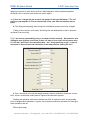
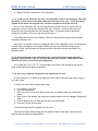
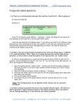
PERM: MS User's Manual © 2013 Geocomp Corp. Frequently Asked Questions Hardware 1. Q: What are the actual zero pressure conditions for the cell and for the bottom and top FlowTrac-II units at the beginning of a permeability test? A: The pressure sensor for each FlowTrac-II unit is internally located; therefore any column of water inside the tubing up to the cell will be registered at the beginning of the test. This assumes that there are no air bubbles trapped inside the lines. Conventionally, the zero pressure is as follows: FlowTrac-II Cell Pressure: FlowTrac-II Bottom Pressure: FlowTrac-II Top pressure: Soil sample mid height Soil sample bottom Soil sample top It is extremely important that the zero pressures are adjusted at the beginning of each test. Otherwise the gradient across the sample may not be correct. To adjust for different samples heights, following these steps for both the cell and top/bottom sample. FlowTrac-II units: 1. At the beginning of the test, open the Output valve (either using the key pad or through the PC). 2. Fill the output line with water, making sure that there are no air bubbles trapped. 3. Raise the line to the location that corresponds to the mid-height of the soil sample, and zero the pressure by placing the Offset value from the System Monitor into the Calibration Summary. 2. Q: Can I fill up the permeability chamber using the FlowTrac-II unit? A: It is not practical to fill up the permeability cell chamber using the FlowTrac-II unit. The total volume of water required to fill up the standard (model 3440) permeability chamber is about 2500 cc, and the total volume capacity of the FlowTrac-II unit is 250 cc. The easiest and most practical way to fill up the permeability chamber is to do so directly from the water faucet. Note: Except when running Ko consolidation, there is no particular requirement for the quality of the chamber water as long as the water is potable. 3. Q: Do I need to use de-aerated water to fill the FlowTrac-II units; if so, how do I obtain de-aerated water? A: Yes, it is important to use de-aerated water to minimize air bubbles in the system, and speed up the back saturation process. To prepare de-aerated water, boil water while Geocomp Corporation · 125 Nagog Park · Acton, MA 01720 · Tel 978-635-0012 · Fax 978-635-0266 PERM: MS User's Manual © 2013 Geocomp Corp. applying a vacuum or use a device such as a Nold DeAerator, which combines propeller cavitation with a vacuum to de-aerate the water rapidly. 4. Q: How can I change the rate at which the pumps fill during initialization? The cell pressure pump appears to fill at a substantially slower rate than the sample pressure pump. A: The filling and emptying rates during the initialization process cannot be changed. Filling involves suction; as a result, the filling rate was determined so that it prevents cavitation from occurring. 5. Q: I am running a permeability test on a compacted sand material. My saturation ratio (Skempton pore pressure coefficient B) does not seem to ever reach the minimum value of 0.95 that I specified in the saturation table. Am I doing something wrong? Is there a technique to improve the initial saturation of the sample before starting the test? A: First, check that your cell and sample pressure sensors calibration values are correct. Next, there is a technique widely used to improve the saturation process: Flushing the specimen with carbon dioxide gas (CO2) to replace as much air as possible prior to backpressure saturation is a great way to improve saturation because CO2 has higher water solubility than air. Follow these steps: Geocomp Corporation · 125 Nagog Park · Acton, MA 01720 · Tel 978-635-0012 · Fax 978-635-0266 PERM: MS User's Manual © 2013 Geocomp Corp. 1. Dip the top drainage line into a small container of clear water and open the valve. 2. Connect regulated source of compressed CO2 to the drainage line at the bottom of the sample. 3. Open valve on CO2 and slowly increase CO2 pressure until bubbles start escaping through the water. Continue flushing sample with CO2 for about 15 minutes. 4. Replace CO2 source with de-aerated water source. 5. Apply small vacuum to top drainage line to force slow upward flow of deaired water into specimen. Continue until no more bubbles show in the top drainage line. For further info please refer to: Rad, N. S., and G. W. Clough (1984). "New Procedure for Saturating Sand Specimens." Journal of the Geotechnical Engineering Division, ASCE, Vol. 110, No. 9, pp. 1205-1218. 6. Q: Could the Node ID# for either one of the FlowTrac-II’s change by itself? What possible reasons could you think to have prompted the change? A: The Node ID cannot change by itself. The Node IDs for the FlowTrac-II units used in permeability tests are 66 for the Cell Pressure unit, 67 for the Bottom Pressure unit and 68 for the Top Pressure unit. If someone rebooted the system and by mistake pressed the ESC key on the keypad of a unit, the embedded controller for that unit reverted back to its default values. The embedded controller default Node ID value for a FlowTrac-II unit is 66. If you suspect the ESC key was pressed during the boot sequence for any unit, go to Section 2.1.4 (Setup) of the hardware manual for that unit. There is a table of settings there. Go through each LCD menu on the unit and compare the setting against that in the table. If there is a difference, change the setting to that in the table. 7. Q: We noticed that a lot of the clays in our specimen had been washed to the top flowpump. We think that the flow-pump might need some washing after some time of use. What is your opinion? Do you have a similar experience? Does the washing of the fine materials into the flow pump affect the readings of the pressure transducer? A: Yes, you do have to flush the FlowTrac-II after extensive use or after a long idle period. 8. Q: Is there any required maintenance for the FlowTrac-II units? A: Except for regular routine pressure sensors calibration, your FlowTrac-II units require only a little maintenance, such as flushing and draining after extensive use or anticipation of prolonged idle time. Flushing the FlowTrac-II units is accomplished by draining the FlowTrac-II pump cylinder manually, using the Empty command on the front LCD. Draining must be done into a separate container than the one you fill from. You need to repeat this operation several times or until you can see that the drained water is clear. Leave the FlowTrac-II empty if you are not going to use it for an extended period of time. Geocomp Corporation · 125 Nagog Park · Acton, MA 01720 · Tel 978-635-0012 · Fax 978-635-0266 PERM: MS User's Manual © 2013 Geocomp Corp. 9. Q: We have several units connected to the same PC. We were running only one of the units, so we shut off the remaining units. Then we got an error message stating that the unit was not responding. It seems that we lost communication with the unit. What is happening? A: A temporary loss of communication is a normal thing when you either shut off or boot up another unit connected to the same network. Any time a unit connected to the network is powered down or powered up, the network goes into a re-configuration mode, during which no communication is allowed. Depending on how many other units are on, this process may take some time. If you're lucky, the Windows software will miss it. If you're not so lucky, you get the normal 'LoadTrac not responding' message. All you have to do is hit the Retry button and you should be all set. 10. Q: After an electrical power problem, it seems that the system is not working properly. We suspect that the set-up values on the embedded controller are not correct. How do we revert to the original set-up values or default values set at the factory? A: The default values may change either after an electrical power problem or due to inadvertent actions by the end user. You will need to revert back to the internal default values of your system by following these steps: 1. Turn off the LoadTrac-II unit and each FlowTrac-II unit. 2. Wait about 10 sec. 3. Turn each back on and immediately press the ESC key on the keypad to reset everything back to the imbedded controller default values. 4. Now go to your LoadTrac-II and FlowTrac-II hardware manuals. In Section 2.1.4 (Setup) of each, you will find a table of default settings for your system. Go through each LCD menu and be sure the settings on the menu agree with those in the table. If a setting does not agree, change it to the one in the manual. 5. If the Node ID numbers on your units were changed (because you are controlling more than one system with your computer), set them to the values they were changed to. 11. Q: Why is the displacement value shown on the System Monitor screen different that the one shown in the Test Monitor screen? A: In all of our software programs, the displacement reading is automatically zeroed at the start of the test; therefore, the offset value in the calibration summary for the LVDTs (displacement transducers) is irrelevant. Also, as a result, the System Monitor (non zeroed value) will show a different value for the displacement from the Test Monitor (zeroed value). That is totally normal and expected. Geocomp Corporation · 125 Nagog Park · Acton, MA 01720 · Tel 978-635-0012 · Fax 978-635-0266 PERM: MS User's Manual © 2013 Geocomp Corp. 12. Q: We are using a sand sample and experiencing problems with water just flowing through the sample and triggering the limit switch. A: The flexible wall permeability test is suitable for soils with certain hydraulic conductivities according to ASTM 5048: 1.3 These test methods may be utilized on all specimen types (undisturbed, reconstituted, remolded, compacted, etc.) that have a hydraulic conductivity less than about 1.3 10−6 m/s (1.3 10−4 cm/s), providing the head loss requirements of 5.2.3 are met. For the constantvolume methods, the hydraulic conductivity typically has to be less than about 1.3 10−7 m/s. 1.3.1 If the hydraulic conductivity is greater than about 1.3 10−6 m/s, but not more than about 1.3 10−5 m/s, then the size of the hydraulic tubing needs to be increased along with the porosity of the porous end pieces. Other strategies, such as using higher viscosity fluid or properly decreasing the cross-sectional area of the test specimen, or both, may also be possible. The key criterion is that the requirements covered in Section 5 have to be met. You should consider using the quick constant head permeability method with this type of soil. 13. Q: How do I bleed the lines and get rid of air bubbles in the cell? A: You can saturate the lines and get rid of air bubbles by following the steps shown below. Using the keypad and the LCD on the front of the FlowTrac-II go to the main menu FlowTrac II. 1. Monitor 2. Position 3. Control Rev: xx.xx.xxxx 4. Setup ID: # Then to 2. Position 5. Control Valves 1. Open output Valve and 4. Close the supply valve if it is not already closed. Position 1. Empty 2. Fill 3. Initialize Output Valve 1. Open 2. Close Valve is closed 4. Jog 5. Control Valves Supply Valve 3. Open 4. Close Valve is closed Next go back to the main menu using the Esc. key on the keypad. Geocomp Corporation · 125 Nagog Park · Acton, MA 01720 · Tel 978-635-0012 · Fax 978-635-0266 PERM: MS User's Manual © 2013 Geocomp Corp. Then to 2. Position4. Jog use the arrow up to push water out of the flow pump into the output line until you see water dripping out. Visually inspect the line and keep on pushing the water out until you get rid of all the air bubbles. 14. Q: Am I correct that we are only saturating the sample from the bottom because the crossover to the top is closed? The usual procedure is to saturate from both the top and bottom of the sample. Does this cause the saturation and consolidation phase to take longer? A: The sample is being saturated and consolidated from both ends despite the cross over because both top and bottom FlowTrac-II’s are active. So it should be the same as the triaxial. Software 1. Q: After running a successful test we ran into troubles with the report. We were not able to generate a report because all links on the report pull-down menu are inactive. Are we missing something, or is the software not entirely installed? A: Once a test is finished or even while it is running: 1. Go to the File menu. 2. Click on Load; this will load the test data on the open window on the desktop. 3. Go back to Report. You should see now the Graph, Settings, and Edit menus all activated. 4. You can change units and scales, and edit the test data points. 5. Remember that every time you change or edit something, you will need to save the file, and load it again. 2. Q: I noticed that the cell volume starts to fluctuate as soon as higher and higher cell pressure (greater than 900 kPa (125 psi) are being applied; see attached graph. Why does it do that? Geocomp Corporation · 125 Nagog Park · Acton, MA 01720 · Tel 978-635-0012 · Fax 978-635-0266 PERM: MS User's Manual © 2013 Geocomp Corp. A: Because of the "stiffness and compliance” of the testing system which is just a small volume of the tubing, you need to adjust the cell PID (Proportional Integral Derivative) parameter controls. These are under Options/PID/Cell Pressure. If you adjust the cell pressure proportional gain from to 1.00 to 0.25, you will see virtually no fluctuation in the pressure once it reaches the target value. The PID control parameters are adjustable due to the nature of the different soil types and large variations in their stiffness, from very soft peat and organic soils to highly overconsolidated clays or even soft to medium rocks. The max PID value is 0.10 (very soft soils) and the minimum is 5.00 (very stiff soils). PID CONTROL Control of the pressure or load is accomplished by using a closed loop controller. At equally spaced time intervals called the control loop period, the controller compares the target load or pressure to the measured load or pressure. The loop error is the difference between the two. The controller uses this error to compute and send a signal to the microstepper motor in order to make adjustments to reduce the error by the next loop period. The signal to the micro-stepper controls the micro-stepper’s position. The loop error computed by the controller at every loop period is nothing but the additional required load or pressure to eliminate the error by the next loop period. In other words, the load rate is the error divided by the loop period. Signal = Error/Loop Period / Stiffness GP = 1/Loop Period/Stiffness Signal (P) = GP * Error The above equation is the basic idea behind any proportional controller where GP is the proportional gain. The controller employed by this system is actually a PID controller, where P is for proportional control, I is for integral control and D is the derivative controller. 3. Q: I calibrated my transducer and filled out the Calibration table under the Options menu. However, I can't get the program to save the new calibration numbers. When I open the file back up the old calibration numbers are still there. How do I save the new calibration data? A: Go to File>Save As. Save the file under a new name such as newtemplate.dat Geocomp Corporation · 125 Nagog Park · Acton, MA 01720 · Tel 978-635-0012 · Fax 978-635-0266 PERM: MS User's Manual © 2013 Geocomp Corp. 4. Q: During the test, a controller error message appears on the screen telling me that a limit switch is on; what should I do? A: Manually close the valve on the permeability cell connected to this FlowTrac-II. Depending on the status of the FlowTrac-II unit, refill if empty, or empty if full. Re-apply the pressure from before the error message; reopen the valve and then click the Retry button. 5. Q: What is the purpose, in general, of the "Initialization" phase? A: Initialization is an important phase that: Allows the user to check the proper functioning of the entire system while it is only applying a small effective stress on the sample Detects early leaks, either through the rubber membrane, the fittings, or the in the cell (acrylic chamber not tightened, O-rings out of alignment…) Applies a small effective stress on the sample, so that the sample state of stresses is moved away from the failure line on a stress path diagram. This will prevent any possible early set-up failure of the sample, especially for very soft clayey soils or very loose sands. 6. Q: What typical magnitudes of stress would you apply during initialization, prior to beginning backpressure saturation? A: Typically you want to apply a small effective stress on the sample, such as 7 or 14 kPa (1 or 2 psi). 7. Q: How long do I have to leave the initialization phase? A: 60 minutes is a sufficient duration to detect any problem. Please note that any phase duration starts from the moment that the desired stresses are reached. If everything checks OK, you do not need to wait for the full 60 minutes; go to the Run menu and click on Next Step to manually override the automation process. 8. Q: I noticed that the engineering readings on the LCD screen are different than the ones on the PC screen. Are they supposed to be the same? Did it affect the results of a test I just ran? A: SYNCHRONIZING LCD AND PC SCREENS: First, I would like to assure you that the mismatch of the engineering readings values between the LCD and the PC screens will not affect the results of any test that you have run through the PC software program. Assuming that your calibration factors are correct, or that you have just finished a new calibration and need to update the calibration parameters on the embedded controller of a Geocomp Corporation · 125 Nagog Park · Acton, MA 01720 · Tel 978-635-0012 · Fax 978-635-0266 PERM: MS User's Manual © 2013 Geocomp Corp. LoadTrac-II or FlowTrac-II or ShearTrac-II, you can synchronize the engineering readings between the LCD and the PC screen by following these steps: 1. Go to the Calibrate Summary menu 2. Select the sensor that you want to synchronize 3. Click on the Download button. This will automatically transfer (copy and save) the current calibration parameters (Factor and Offset) into the embedded controller. 4. Repeat the above procedure for the other sensors. 9. Q: Can the software detect wrong values that are manually entered by the end user? A: Yes, the software program detects any erroneous data entry; examples include: 1. Negative values for sample dimensions, calibration factors, and PID control parameters 2. Zero values for sample dimensions, calibration factors (except for offset value), and PID control parameters 3. Wrong Node ID number 4. A malfunctioning sensor that it is giving an analog reading of either 0 (the minimum value) or 65535 (the maximum value) 5. Any unit (LoadTrac-II or FlowTrac-II) that is not on. 10. Q: I am running a test. Do I need to wait until the end of the test to see the results? A: You do not need to wait until the end of the test. While the test is running: 1. Go to the File menu. 2. Select Load. 3. Go to the Report menu. You should now be able to see the partial data up to the point when you did the Load. Geocomp Corporation · 125 Nagog Park · Acton, MA 01720 · Tel 978-635-0012 · Fax 978-635-0266 PERM: MS User's Manual © 2013 Geocomp Corp. 4. Repeat the above steps as the test progresses. 11. Q: In many of our different test files, the calibration values in the Summary Table and the values in each sensor's individual calibration table are not in sync. Could you please explain which values the program uses, and how to make sure they are correct? A: All of the Geocomp Corp. control programs have similar menus for performing the calibration of any of the sensors related to the test. However, you must then copy the calibration that you obtained into the Summary Table. (If you have had to repeat the calibration procedure, be sure to use the correct value.) The calibration factors in the Summary Table are the ones that the particular program uses when running a test. Note that it is possible to have no calibration data in the calibration menu if you calibrate a sensor with one program (for example, PERM) and later use a different program (for example, ICON). Each program will always uses the calibration factors contained in its Summary Table. 12. Q: At the beginning of the saturation phase I noticed that the B value (minimum saturation ratio) went as low as -5 and then got back up to positive values after a while. What should I do to prevent this from happening? A: Increase the T's (T1, T2, T3, T4) by doubling the values; this would give the system time to settle down and adjust accordingly. 13. Q: How do you delete a bad point at the completion of a test? A: First find out if it is really a bad data point that is due to an electrical power surge or any other cause. If such is the case, follow these simple steps: 1. Go to Report, then Edit 2. Locate the bad point 3. Move the cursor to the first column and to the row number that you would like to delete 4. Right click on the mouse; you should see a small window with the message "Delete and Insert" 5. Click on Delete; the row with the bad point will be deleted 6. Save the file with a new name. You must always keep the original test file intact. The reported value should match the Test Monitor value unless other corrections are involved such as machine compressibility. Geocomp Corporation · 125 Nagog Park · Acton, MA 01720 · Tel 978-635-0012 · Fax 978-635-0266 PERM: MS User's Manual © 2013 Geocomp Corp. 14. Q: We would like to run a perm test on a sample at 10 psi consolidation pressure, then run it again at 103 kPa (15 psi), then 138 kPa (20 psi) , and so on. Is there a way to run it without losing the pressures initially created through the initialization phase and saturation phase? A: One way to do it is to run separate tests starting from the consolidation phase by skipping both the initialization and saturation phases. To do so you need to either input zero’s in both phases or click Consolidation/B under test parameters tab (see attached) , and make sure at a the start of the test to click NO to both initializing the platen and FlowTracII’s. Geocomp Corporation · 125 Nagog Park · Acton, MA 01720 · Tel 978-635-0012 · Fax 978-635-0266