1
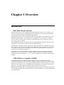
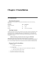
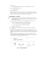
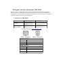
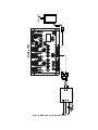
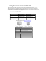
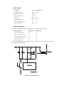
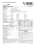
DMC-40x0 Installation Manual-ETL
DMC-40x0 Integrated
Amplifier Installation
Manual
Manual Rev. 1.0c
By Galil Motion Control, Inc.
Galil Motion Control, Inc.
270 Technology Way
Rocklin, California 95765
Phone: (916) 626-0101
Fax: (916) 626-0102
E-mail Address: [email protected]
URL: www.galilmc.com
Rev 03/18/10
Using This Manual
This manual provides information for the wiring, installation, powering-up, and basic communication
to the DMC-40x0 motion controller with the Galil internal amplifiers, AMP-43040 and SDM-44140.
The following list of part numbers are examples of configurations of the DMC-40x0 motion controller
that are covered in this manual.
DMC-4080 -D3040-D3040
DMC-4080 -D4140-D4140
This manual covers the basic installation of the controller and amplifier modules. For full operational
information including specific I/O installation, detailed programming examples and additional internal
driver information, see the DMC-40x0 User Manual.
WARNING: Machinery in motion can be dangerous! It is the responsibility of the user to
design effective error handling and safety protection as part of the machinery. Galil shall
not be liable or responsible for any incidental or consequential damages.
If the DMC-40x0 motion controller and included amplifiers or stepper drivers are not used
in a manner specified by Galil Motion Control, the protection provided by the controller,
amplifiers and drivers may be impaired.
Chapter 1 Overview
Introduction
DMC-40x0 Motion Controller
The DMC-40x0 Series are Galil’s highest performance stand-alone controller. The controller series
offers many enhanced features including high speed communications, non-volatile program memory,
faster encoder speeds, and improved cabling for EMI reduction.
Each DMC-40x0 provides two communication channels: high speed RS-232 (2 channels up to 115K
Baud) and 10BaseT Ethernet. The controllers allow for high-speed servo control up to 22 million
encoder counts/sec and step motor control up to 6 million steps per second. Sample rates as low as
31.25 µsec per axis are available.
A Flash EEPROM provides non-volatile memory for storing application programs, parameters, arrays
and firmware. New firmware revisions are easily upgraded in the field.
The DMC-40x0 is available with up to eight axes in a single stand alone unit. The DMC-4010, 4020,
4030, 4040 are one thru four axes controllers and the DMC-4050, 4060, 4070, 4080 are five thru eight
axes controllers. All eight axes have the ability to use Galil’s integrated amplifiers or drivers and
connections for integrating external devices.
Commands can be sent in either Binary or ASCII. Additional software is available for automatictuning, trajectory viewing on a PC screen, CAD translation, and program development using many
environments such as Visual Basic, C, C++ etc. Drivers for Windows XP (32 & 64 bit), and Linux are
available.
AMP-43040 Servo Amplifier (-D3040)
The AMP-43040 (four-axis) and AMP-43020 (two-axis) are multi-axis brush/brushless transconductance PWM amplifiers that are capable of handling 7Amps of continuous current and 10Amps
of peak current with any one axis. The average continuous current per four-axis amplifier is 6A, with a
maximum current output of 25A. The AMP-43040/43020 Brushless drive modules are connected to a
DMC-40x0. The standard amplifier accepts DC supply voltages from 20-68 VDC.
NOTE: When the AMP-43040 is ordered with the ETL option, Chopper mode must be used. See the
AU command in the DMC-40x0 Command Reference for more information on setting the AMP-43040
into Chopper Mode.
SDM-44140 Stepper Amplifier (-D4140)
The SDM-44140 microstepper module drives four bipolar two-phase stepper motors with 1/64
microstep resolution (the SDM-44140 drives two). The current is selectable with options of 0.5, 1.0,
2.0, & 3.0 Amps per axis. The standard SDM-44140 accepts DC supply voltages from 20-60 VDC.
Chapter 2 Installation
Pre-Installation
Operating Environment
The location for use of the DMC-40x0, AMP-43040 and SDM-44140 must meet the following
requirements.
Description
Units
Specification
Ambient Temperature
C
0 to +70
Altitude
feet
10,000
Humidity
RH
20-95% (non-condensing)
Mounting Location
The DMC-40x0 motion controller must be mounted on a flat surface using the 4 mounting holes found
on the metal base-plate. The grating found on the side of the metal must not be obstructed in order
provide proper air flow for adequate heat dissipation. The dimensions for a 1-4 axis controller are
smaller than that of a 4-8 axis controller, these dimensions and the mounting hole locations are found
in Appendices A3 and A4.
Additional Mounting Consideration when using the AMP-43040
When operating a DMC-4080- D3040-D3040 or a DMC-4040-D3040, special mounting
considerations must be made if the total continuous current output for the controller is greater than 15A
for a 3-4 axis controller and greater than 30A for a 5-8 axis controller (standard mounting is adequate
for a 1 or 2 axis controller). In this case, the controller base must be mounted to an addition heat sink.
Elements Needed for Installation
1.
DC power supply
a.
2.
Ratings found in Appendix A1
Power Supply Cable
a.
Cable from DC power supply to power input for AMP-43040 or SDM-44140.
b.
DMC-4080 controller requires 2 cables.
3.
PC or laptop with Ethernet and/or RS-232 ports
4.
GalilTools, or GalilTools-Lite software package
5.
Ethernet Cable
a.
6.
Recommended shielded Cat 5 STP cable. Straight-through or Cross-over.
RS-232 straight-through serial cable
a.
9 pin D-sub female
7.
Molex pin Crimp Tool
8.
Additional cables may be required for connection to motors, external amplifiers, digital or
analog I/O, and other devices. See the full DMC-40x0 User Manual for further information.
9.
Disconnect switch or circuit breaker for AC power to DC Power Supply
Unpacking the Controller
Caution:
1.
The DMC-40x0 motion controller and included internal amplifier include electrostatic
sensitive components. Observe standard precautions for handling ESD sensitive devices
when handling the controller.
Verify that the following components have been shipped along the motion controller.
•
•
Note:
Connectors and mating pins for motor power and amplifier power.
o
Qty 4 – 4 pin molex connectors for EACH internal amplifier
o
Qty 1 – 6 pin molex connector for EAH internal amplifier
Galil Software Installation CD
Connectors and/or software installation CD may not be shipped to existing OEM
customers.
2.
Check that no visible damage has occurred to the controller, or internal amplifiers. If any
damage has occurred to the controller, or the components shipped with the controller, contact
Galil Motion Control immediately. Contact information can be found in the beginning of this
manual.
3.
Verify the controller that has been shipped to you is in fact the controller that you have
ordered from Galil or your authorized Galil distributor. To do this, check the labeling on the
controller and compare it to the part number that was ordered.
Figure 1: Label for DMC-40x0
Figure 2: Label for DMC-40x0-D3020
Figure 3: Label for DMC-40x0-D3040
Figure 4: Label for DMC-40x0-D3040-D3020
Figure 5: Label for DMC-40x0-D3040-D3040
Figure 6: Label for DMC-40x0-D3040-D4120
Figure 7: Label for DMC-40x0-D3040-D4140
Figure 8: Label for DMC-40x0-D4120
Figure 9: Label for DMC-40x0-D4140
Figure 10: Label for DMC-40x0-D4140-D3020
Figure 11: Label for DMC-40x0-D4140-D3040
Figure 12: Label for DMC-40x0-D4140-D4120
Figure 13: Label for DMC-40x0-D4140-D4140
Figure 14: ETL Mark
Installation
Mounting the Controller
The DMC-40x0 motion controller must be mounted to a flat surface with 4 – #10 pan head screws
through each mounting hole found on the controller base as shown in Figure 15. If the controller is
mounted on a wall, the controller should be mounted so that the bottom of the controller is horizontal
to the floor (as shown in Figure 15).
If the AMP-43040 internal amplifiers are being used, it should be determined at this time whether or
not an additional heat sink will be required. This is determined based upon the continuous current
requirements of the system as defined in the “Additional Mounting Consideration when using the
AMP-43040” section above. The Motor Sizer tool found on our website can be used to determine this
value http://www.galilmc.com/learning/motorsizer.php.
(Bottom of Controller)
Figure 15: Mounting the DMC-4000
Wiring the Controller with internal AMP-43040
The basic wiring for a DMC-40x0 motion controller with included AMP-43040 servo amplifiers is
shown in Figure 16. The disconnect switch or circuit breaker for AC power must be installed in a
location that is in close proximity to the equipment and within easy reach of the operator. It must also
be marked as the disconnect device for the equipment.
Connectors for AMP-43040
POWER
A,B,C,D: 4-pin Motor
Power Connectors
On Board Connector
Terminal Pins
6-pin MATE-N-LOK
MOLEX# 39-31-0060
MOLEX#44476-3112
4-pin MATE-N-LOK
MOLEX# 39-31-0040
MOLEX#44476-3112
For mating connectors see http://www.molex.com/
Power Connector
Pin Number
Connection
1,2,3
DC Power Supply Ground
4,5,6
+VS (DC Power)
Motor Connector
1
Phase C (N/C for Bushed Motors)
2
Phase B
3
No Connect
4
Phase A
Figure 16: DMC-4000 wiring with AMP-43040
Wiring the Controller with internal SDM-44140
The basic wiring for a DMC-40x0 motion controller with included SDM-44140 stepper drivers is
shown in Figure 17. The disconnect switch or circuit breaker for AC power must be installed in a
location that is in close proximity to the equipment and within easy reach of the operator. It must also
be marked as the disconnect device for the equipment.
Connectors for SDM-44140
POWER
A,B,C,D: 4-pin Motor
Power Connectors
On Board Connector
Terminal Pins
6-pin MATE-N-LOK
MOLEX# 39-01-2065
MOLEX#44476-3112
4-pin MATE-N-LOK
MOLEX# 39-01-2045
MOLEX#44476-3112
For mating connectors see http://www.molex.com/
Power Connector
Pin Number
Connection
1,2,3
DC Power Supply Ground
4,5,6
+VS (DC Power)
Motor Connector
1
B-
2
A-
3
B+
4
A+
Figure 17: DMC-4000 wiring with SDM-44140
Communication Connection
Connect the serial cable or the Ethernet cable from your PC to the DMC-40x0 motion controller. The
Ethernet cable may be connected through a hub or switch, or directly to the PC.
If the controller is connected to a DHCP enabled network, the IP address will automatically be
assigned to the controller.
Additional Wiring
Additional wiring to the Analog and Digital I/O, encoders, limit switches and other connections found
on the D-Subs on the DMC-40x0 motion controller will be required to complete your applications. For
detailed information regarding these connections, see the DMC-40x0 User Manual.
Powering the Controller
Once the connections have been made from the DC power supply to the DMC-40x0 motion controller,
the controller and internal amplifiers may be powered-up. At this time the Power LED should be
illuminated, and the LCD should turn on and indicate the status of the axes available on the controller.
Communication with Galil Software
To communicate with the controller, the GalilTools communications software must first be installed.
A free version of GalilTools (GalilTools-Lite) may also be used. These software applications can be
found on the software installation CD shipped with the controller, or online at:
http://www.galilmc.com/support/software-downloads.php
Installation instructions for your operating system can be found in the GalilTools user manual.
http://www.galilmc.com/support/manuals/galiltools/introduction.html
Once the software has been installed, run GalilTools, or GalilTools-Lite and choose your controller.
RS-232 connection
If you are using over a serial connection, the standard baud rate of the DMC-40x0 motion controller is
115200. For a standard serial connection over COM1, choose COM1 115200 in the connections
dialog window.
Ethernet connection
If you are connected to the controller via an Ethernet connection, and your network is DHCP enabled,
then the controller will automatically have an IP addressed assigned to it. If your network is not
DHCP enabled, or the connection is only between the PC and the controller, then the controller be
found with the software as no IP address assigned. The GalilTools software will allow you to assign
the controller with an IP address. See the GalilTools documentation for detailed information on using
the software to assign the controller IP address.
Appendix – Specifications
A1 – Electrical Specifications
DMC-4080- D3040-D3040
Description
Units
Specification
Maximum Input Voltage
VDC
68
Minimum Input Voltage
VDC
20
Maximum Current Output
Amps
50
Description
Units
Specification
Maximum Input Voltage
VDC
60
Minimum Input Voltage
VDC
20
Maximum Current Output
Amps
38
Description
Units
Specification
Supply Voltage
VDC
20-68
Maximum Avg cont. current per 4 axes
Amps
6
Continuous Current per axis
Amps
7
Peak Current per axis
Amps
10
Nominal Amplifier Gain
A/V
0.7
Switching Frequency
Hz
60
Minimum Load Inductance:
mH
0.2 (Chopper Mode)
Brushless Motor Commutation angle
°
120
°
60 (option available)
Amps
30
DMC-4080- D4140-D4140
AMP-43040
Supply Voltage Fuse
SDM-44140
Description
Units
Specification
DC Supply Voltage:
VDC
20-60
Max Current (per axis)
Amps
3.0
Max Step Frequency:
MHz
6
Motor Type:
Bipolar 2 Phase
Switching Frequency:
Hz
60
Minimum Load Inductance:
mH
0.5
Supply Voltage Fuse
Amps
20
Fault Information
The AMP-43040 and SDM-44140 are protected from the following fault conditions.
Fault Condition
AMP-43040
SDM-44140
Over-Current Protection
yes
yes
Under-Voltage Protection
yes
yes
Over-Temperature Protection
yes
yes
Over-Voltage Protection
yes
no
Hall Error Detection
yes
no
The Over-Current protection circuit is shown in Figure 18. For further specifics on fault conditions,
see the DMC-40x0 User Manual.
Figure 18: Overcurrent Circuit
A2 – Environmental Specifications
Description
Units
Specification
Storage Temperature
C
-40 to +125
Operating Temperature
C
0 to +70
Operating Altitude
feet
10,000
Humidity
RH
20-95% (non-condensing)
A3 – Mechanical Specifications DMC-4080
DMC-4080- D3040-D3040
Included Components
Quantiy
Description
DMC-4080
1
Main Controller Board
CMB-41012
1
Communications Board
ICM-42000
2
Interconnect Module
AMP-43040
2
Servo Amplifier Board
DMC-4080- D4140-D4140
Included Components
Quantiy
Description
DMC-4080
1
Main Controller Board
CMB-41012
1
Communications Board
ICM-42000
2
Interconnect Module
AMP-43040
2
Servo Amplifier Board
DMC-4080
Description
Units
Specification
Weight
lb
4.35 (DMC-4080-D3040-D3040)
Length
in
11.50
Width
in
7.25
Height
in
1.41
A4 – Mechanical Specifications DMC-4040
Description
Units
Specification
Weight
lb
2.9 (DMC-4040-D3040)
Length
in
8.05
Width
in
7.25
Height
in
1.41