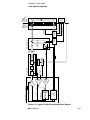
1
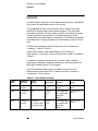
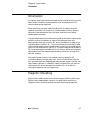
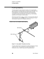
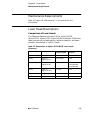
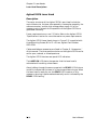
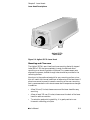
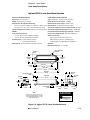
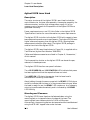
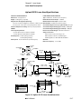
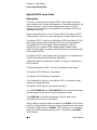
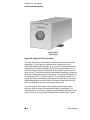
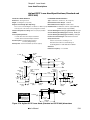
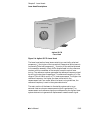
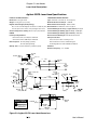
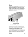
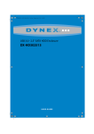
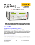
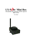
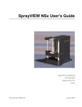
5
Laser Heads
Chapter 5 Laser Heads
General
General
One laser head is required in most measurement systems, regardless of
the number of measurement axes in the system.
The wavelength of light from the laser head is used as the length
standard for Agilent laser measurement systems. The laser head
generates a coherent (all light waves in phase), collimated (all waves
traveling parallel to one another), light beam consisting of two
orthogonally polarized frequency components. To differentiate between
the frequencies, the lower frequency is identified as f1 and the higher
as f2.
The difference between these two frequencies is the “Reference
Frequency”, listed in Table 5-1.
Agilent offers several laser head models to fill a variety of
requirements. A summary listing of Agilent laser heads is provided in
Table 5-1.
In addition to system information for the laser heads, complete
descriptions, equipment supplied information, and specifications for
each laser heads are given in this chapter.
Each of these laser heads requires a cable to connect it to the
measurement system electronics. Cables are listed in Chapter 9,
“Accessories,” of this manual.
Table 5-1. Laser Heads Summary
Agilent
Model
5517A
Reference
Requency
Beam
Diameter
Polarization
Indicators
Shutter
1.5 MHz to
6 mm
f1 Horiz
LASER ON
f2 Vert
READY
Open, reduced,
closed
f1 Horiz
+15V POWER ON
f2 Vert
−15V POWER ON
2.0 MHz
5517B
1.9 MHz to
6mm
2.4 MHz
Open, reduced
closed
LASER ON
READY
5517C
2.4 MHz to
6 mm (std)
f1 Horiz
+15V POWER ON
3.0 MHz
3 mm (5517C-003)
f2 Vert
−15V POWER ON
9 mm (5517C-009)
Open, reduced
closed
LASER ON
READY
5-2
User’s Manual
Chapter 5 Laser Heads
Frequencies and Polarizations
Table 5-1. Laser Heads Summary (Continued)
Agilent
Model
Reference
Requency
Beam
Diameter
Polarization
Indicators
Shutter
5517D
3.4 MHz to
4.0 MHz
6 mm
f1 Horiz
+15V POWER ON
f2 Vert
-15V POWER ON
Open, reduced
closed
LASER ON
READY
5519A
2.4 to
6 mm
3.0 MHz
f1 Horiz
LASER ON
f2 Vert
SIGNAL
Turret ring
configures for
READY
straightness or
other measurement
5519B
3.4 to
Same as 5519A
4.0 MHz
Same as
5519A
Same as 5519A
Same as 5519A
F1 is the lower frequency, and f2 is the higher frequency. The Agilent 5517A is the basic laser head.
The Agilent 5517B, Agilent 5517C, and Agilent 5517D are smaller
packages than the Agilent 5517A.
The Agilent 5517B, Agilent 5517C, and Agilent 5517D have higher
reference frequencies than the Agilent 5517A. The higher frequencies
allow higher axis velocity capability, depending on the electronics used.
The Agilent 5519A and Agilent 5519B are designed to be used as a part
of the Agilent 5529A Dynamic Calibrator system. The Agilent 5519B
has a higher frequency that the Agilent 5519A. The higher frequency
allows higher axis velocity capability.
Frequencies and Polarizations
Agilent laser heads produce a coherent, collimated, two-frequency laser
beam consisting of two orthogonally polarized frequency components.
Frequencies f1 (the lower frequency) and f2 are always orthogonally
polarized with respect to one another. However, either may be
vertically (or horizontally) polarized. Agilent laser heads have f1
horizontally polarized. Polarization affects the direction sense. For
example, if
•
f1 (the lower frequency) is in the measurement path,
•
f2 is in the reference path, and
•
the optics are moving away from each other, the fringe counts will
be increasing. Interchanging f1 and f2 in this example will cause the
fringe counts to decrease.
User’s Manual
5-3
Chapter 5 Laser Heads
Number of Measurement Axes
Before the laser beam leaves the laser head, part of it is sampled to
determine the difference frequency between its two optical
components. This difference frequency is called the Reference
Frequency or Split Frequency.
The beam leaving the laser head is directed through a configuration of
beam-directing optics and measurement optics and then to a receiver.
The receiver provides a Measurement Frequency, which, when
compared to the Reference Frequency from the laser head, yields
displacement information.
If a measurement axis is used for wavelength tracking instead of a
displacement measurement, its Measurement Frequency yields
wavelength-of-light information instead of displacement information.
Number of Measurement Axes
The output from a single laser head can be used for measurements
involving many axes of motion, plus the wavelength tracking
compensation axis. The number of axes that can be measured depends
on the optical power available from the laser head and the optics and
system measurement electronics being used.
Measurement Range
Nominal optical measurement range for the system is 40 meters
(130 feet) for the sum of all axes when using a laser head with a
(standard) 6 mm beam.
Heat Generation
There is some heat dissipation from the laser heads. Where possible,
install the laser head far enough away from the measurement area to
avoid any thermal effects. On a small or very accurate machine, choose
the mounting method and location with care.
5-4
User’s Manual
Chapter 5 Laser Heads
Accuracy Considerations
Accuracy Considerations
The wavelength of light from the laser head serves as the length
standard for Agilent laser measurement systems. Since the laser
transition of the neon atom provides a fundamental physical reference,
the Agilent interferometric system is considered a “primary standard”
for metrology.
The standard long-term wavelength accuracy (in a vacuum) of Agilent
laser heads is 0.1 part-per-million (1 × 10⁻⁷ ) or 0. 1 micron per meter
(0. 1 microinch per inch). It is customary to specify laser accuracy in
vacuum because the variable characteristics of air (such as
temperature, humidity, pressure, and gas mixture) have a significant
effect on the wavelength of light.
As with any measuring device, improper installation or operation can
degrade measurement accuracy. Before installing the equipment, you
should study the basic measurement capabilities of the system, along
with considerations of relevant sources of errors. Many potential
problems that could be encountered during installation and initial
operation can be avoided by careful planning and a thorough
understanding of laser interferometry.
Motion of the receiver or laser head along the beam path (X) has no
effect on the measurement, since both f1 and f2 would exhibit Doppler
shift.
Small motions of the laser head, receiver, interferometer, or
retroreflector in a direction perpendicular to the beam path (Y or Z)
have no effect on the measurement. The only restriction is that
sufficient light returns to the receiver.
Angular motion of the laser head about the Z or Y axis has the effects
described below:
•
It introduces a measurement error (cosine error).
•
It may displace the laser beam so that insufficient light returns to
operate the receiver.
User’s Manual
5-5
Chapter 5 Laser Heads
Vibration Isolation
Vibration Isolation
Since the system measures only the relative motion between the
interferometer and reflector, measurements are not affected by
vibration along the beam axis of the laser source or the receiver.
When vibration of the laser head causes displacement of the beam
(perpendicular to beam axis) at an interferometer or receiver, the beam
signal power can fluctuate. If this fluctuation is too great, insufficient
beam signal will arrive at the receiver, causing a “measurement signal
error.”
Automatic Tuning and Warmup Period
To maintain a stable frequency output, Agilent laser heads have
thermally-stabilized cavity lengths controlled by automatic tuning
circuitry.
Thermal stabilization requires a warmup period. The typical warmup
period is four minutes. The maximum warmup period is ten minutes.
Beam Shutters
To facilitate alignment and meet safety standards, the laser heads
have shutter controls installed at the laser beam exit aperture. The
beam may be blocked entirely for safety, reduced for alignment, or
unimpeded for normal operation.
The Agilent 5517A, Agilent 5517B, Agilent 5517C, Agilent 5517D, and
Agilent 5519A/B laser heads have different shutter arrangements. The
shutter arrangements for each laser head is described in the “Laser
Head Descriptions” section in this chapter.
5-6
User’s Manual
Chapter 5 Laser Heads
Orientation
Orientation
An Agilent laser head may be mounted in any orientation as long as its
beam enters the optical system parallel to or orthogonal with the
machine axes being measured.
When mounting the laser head vertically with the beam directed
upward, be careful not to mount an interferometer directly above it,
because of heat dissipation from the laser head that may reduce
measurement accuracy.
The plane defined by the three mounting feet on the laser head must be
parallel to either the bottom or sides of the beam-splitters and
beam-bender housings to within ±3°, and to the bottom or sides of the
interferometers to within ±1°. This ensures that the polarization axes
of the interferometers are oriented properly relative to the polarization
vectors of the laser beam (Figure 5-1). The laser head can be rotated in
90° increments about the beam axis (roll) without affecting the system
performance, but the measurement direction sense will change with
each 90° rotation.
Although the laser head or the receiver may be rotated in 90°
increments about the beam axis (roll), other roll deviations from the
four optimum positions degrade the measurement signal. If either the
laser head or receiver is rotated 45° about the beam axis, all position
information will be lost because the receiver will not be able to
distinguish between the two frequencies.
Magnetic Shielding
Agilent laser heads contain a permanent magnet. When installing an
Agilent laser measurement system in an application sensitive to
magnetic fields, shielding around the laser head may be required.
User’s Manual
5-7
Chapter 5 Laser Heads
Pointing Stability
Pointing Stability
The alignment of the laser beam with respect to the mounting feet
(pointing stability) changes slightly during warm-up of the laser head.
Beam alignment is then stable once the laser head has reached
thermal equilibrium (typically about 30 minutes). This alignment
change during warm-up of the laser head is less than 2 arc-minutes
(typically 1 arc-minute) for the 6 mm beam.
When aligning the laser, optics, or receiver, be sure the laser head has
been powered-on until the READY LED is on (not flashing). This will
assure proper alignment for subsequent power-ups.
LASER POSITION TRANSDUCER MOUNTING
Beam S plitter
90
˚±
3˚
Beam Bender
˚±
90˚
3˚
±3
˚
Figure 5-1. Laser position Transducer mounting
The laser heads should not be exposed to ambient temperature change
greater than ±5° C during operation to keep pointing stability
variations to within a few arc-seconds during measurements.
5-8
User’s Manual
Chapter 5 Laser Heads
Maintenance Requirements
Maintenance Requirements
Refer to Chapter 10, “Maintenance,” in this manual for this
information.
Laser Head Descriptions
Comparison of Laser Heads
The differences between the Agilent 5517A, Agilent 5517B,
Agilent 5517C, Agilent 5517D, Agilent 5519A, and Agilent 5519B laser
heads (and options) are package size, reference frequency, and beam
diameter, summarized in Table 5-2, below.
Table 5-2. Comparison of Agilent 5517A/B/C/D Laser Heads
(Summary)
Agilent Model
Package Size
Reference
Frequency (MHz)
Beam Diameter
(nominal)
5517A
Large
1.5 to 2.0
6 mm
5517B
Same as
Agilent 5517C
1.9 to 2.4 mm
6 mm
5517C
Same as
Agilent 5517B
2.4 to 3.0
6 mm (Standard)
3 mm (Opt. 003)
9 mm (Opt. 009)
5517D
Same as
Agilent 5517B/C
3.4 to 4.0
6 mm
5519A
Large
2.4 to 3.0
6 mm
5519B
Large
3.4 to 4.0
6 mm
User’s Manual
5-9
Chapter 5 Laser Heads
Laser Head Descriptions
Agilent 5517A Laser Head
Description
The major structures of the Agilent 5517A Laser Head include the
control electronics, the laser tube assembly, the sampler assembly, the
reference receiver, and the high voltage power supply. All of the
necessary control signals for the operation of the Agilent 5517A are
generated internally.
Power requirements are + and −15 Volts. Refer to the Agilent 5517A
“Specifications” section for more information on power requirements.
The Agilent 5517A Laser Head, shown in Figure 5-2, is supplied with
three Mounting Screws, M8 × l.2 × 25 mm, Agilent Part Number
0515-0798.
Cables available as accessories are listed in Chapter 9, “Accessories,”
of this manual. The three-position shutter on the Agilent 5517A can be
set for open, reduced, or closed apertures.
The Agilent 5517A has two rear-panel LED indicators.
The LASER ON LED alerts the operator that the laser head is
activated and is emitting a laser beam.
About halfway through the warm-up period, the READY LED blinks on
and off to indicate that the laser is in the process of warming up. When
the laser head is ready for use, the READY LED remains on. Any
necessary retuning is performed automatically and is indicated by the
READY LED flashing.
5-10
User’s Manual
Chapter 5 Laser Heads
Laser Head Descriptions
AVO
LASE ID EXPOSU
EMITTE
R
R
D FRORADIATIONE
M THIS
IS
APER
ATUR
E
Agilent 5517A
Laser Head
Figure 5-2. Agilent 5517A Laser Head
Mounting and Clearance
The Agilent 5517A Laser Head has three mounting feet with tapped
holes (M8 × 1.25) that go completely through the feet and allow
mounting on a mounting plate or bulkhead. For measurement-axis
alignment purposes, slotted through holes should be provided in the
mounting surface.
Aluminum is the preferred material for any mounting surface, since
this will match the thermal coefficient of expansion of the laser base. If
aluminum cannot be used, kinematic mounting of the rear mounting
foot is recommended to minimize stresses due to temperature changes.
In addition:
•
Allow 50 mm (2 inches) clearance around the laser head for easy
servicing.
•
Allow at least 125 mm (5 inches) clearance at the back of the laser
head for cable connections.
•
To maintain good pointing stability, it is good practice to use
kinematic mounting principles.
User’s Manual
5-11
Chapter 5 Laser Heads
Laser Head Descriptions
The laser head emits a laser beam containing a vertically polarized
component, f2 (the higher of the two optical frequencies), and a
horizontally polarized component f1. A portion of the emitted beam is
directed to the sampler assembly. Most of this sample feeds into the
reference receiver and the remainder of the sample is used to control
laser tuning. The reference receiver generates the reference frequency
signal by mixing the two laser frequencies. The reference frequency is
in the range of 1.5 to 2.0 MHz and is a TTL-level square wave. The
higher the reference frequency, the higher the slew rate at which the
measurement optic can move. When the laser tuning stabilizes, the
reference frequency is sent to the system electronics.
The main portion of the beam is directed by system optics to an
external receiver where a measurement signal is generated. The
measurement and reference signals are compared by the Agilent laser
system electronics to generate a displacement measurement signal.
5-12
User’s Manual
Chapter 5 Laser Heads
Laser Head Descriptions
Agilent 5517A Laser Head Specification
PHYSICAL CHARACTERISTICS
LASER BEAM CHARACTERISTICS
Dimensions: See figure below
Type: Helium-Neon, Continuous, Two-Frequency
Weight: 5.5 Kilograms (12 pounds)
Maximum Beam Power Output: 1 milliwatt
Magnetic Field Strength (Non-Operating):
Minimum Beam Power Output: 180 microwatts
Does not exceed 5.25 milligauss at a distance of 460 cm (15 ft) Beam Diameter: 6 millimeters (0.25 inch) typical
from any point on the surface of the packaged Laser Head.
Vacuum Wavelength Accuracy (3 sigma, lifetime): ±0.1 ppm
Clearance Required for Cabling: 12.00 cm (4.72 in) beyond back Vacuum Wavelength Stability (typical 1 hour): ±0.002 ppm
Vacuum Wavelength Stability (typical lifetime): ±0.02 ppm
POWER
Power Input Requirements:
Nominal Vacuum Wavelength: 632.99137 nanometers
+15 Volts ±0.3 Volts at 2.5 Amperes maximum
Safety Classification:
−15 Volts ±0.3 Volts at 0.02 Ampere maximum
Class II Laser Product conforming to U.S.
Heat Dissipation: 23 watts (during operation)
National Center for Devices and Radiological
35 watts (during warmup)
Health Regulations 21 CFR 1040.10 and 1040.11.
Warmup Time: less than 10 minutes (4 minutes typical)
OUTPUTS
Reference Frequency: 1.5 - 2.0 MHz
M8×1.25 Thread
3 Places
83.8 mm
(3.30)
167.5 mm
(6.59)
142.0 mm
(5.59)
360.0 mm
(14.17)
13.0 mm
(0.51)
458.0 mm
(18.03)
479.0 mm
(18.85)
120 mm min clear
(4.72)
83.8 mm
(3.30)
118.0 mm
(4.65)
435.0mm
(17.13)
25.0 mm
(0.98)
AVOID EXPOSURE
LASER RADIATION IS
EMITTED FROM THIS APERTURE
CAUTION
LASER LIGHT
DO NOT STARE INTO BEAM
83.0 mm
(3.27)
MAXIMUM OUTPUT: 1 mw
PULSE SPEC: continuous wave
LASER MEDIUM: helium neon
CLASS II LASER PRODUCT
192.0 mm
(7.56)
22.3 mm Dia
(0.88)
Note
This is a Class II Laser Product conforming to Federal Bureau of Radiological Health Regulations 21 CFR
1040.10 and 1040.11.
118.0 mm
(4.65)
55.1 mm
(2.17)
49.5 mm
(1.95)
CAUTION
LASER LIGHT
DO NOT STARE INTO BEAM
MAXIMUM OUTPUT: 1 mw
PULSE SPEC: continuous wave
LASER MEDIUM: helium neon
CLASS II LASER PRODUCT
Figure 5-3. Agilent 5517A Laser Head dimensions
User’s Manual
5-13
Chapter 5 Laser Heads
Laser Head Descriptions
Agilent 5517B Laser Head
Description
The major structures of the Agilent 5517B Laser Head include the
control electronics, the laser tube assembly, the sampler assembly, the
reference receiver, and the high voltage power supply. All of the
necessary control signals for the operation of the Agilent 5517B are
generated internally.
Power requirements are + and -15 Volts. Refer to the Agilent 5517B
“Specifications” section for more information on power requirements.
The Agilent 5517B is similar to the Agilent 5517A with respect to laser
beam polarizations and current requirements. The Agilent 5517B has a
higher reference frequency than the Agilent 5517A, allowing faster
measurement velocities (slew rates). The Agilent 5517B package is
smaller than that of the Agilent 5517A.
The Agilent 5517B Laser Head, shown in Figure 5-4, is supplied with a
Test Polarizer (Agilent Part Number 1000-0616).
Cables available as accessories are listed in Chapter 9, “Accessories,”
of this manual.
The three-position shutter on the Agilent 5517B can be set for open,
reduced, or closed apertures.
The Agilent 5517B has four rear-panel indicators.
The +15V POWER ON and -15V POWER ON LEDs indicate that power
has been applied and that the respective fuses are intact.
The LASER ON LED alerts the operator that the laser head is
activated and is emitting a laser beam.
About halfway through the warm-up period, the READY LED blinks on
and off to indicate that the laser is in the process of warming up. When
the head is ready for use, the READY LED remains on. Any necessary
retuning is performed automatically and is indicated by the READY
LED flashing.
Mounting and Clearance
The Agilent 5517B Laser Head can be fastened down using the
mounting feet or six tapped holes on the base of the head. The
mounting feet have clearance slots for 1/4-20 or M6 screws.
Alternatively, the mounting feet can be removed and the head fastened
using the 8-32 UNC tapped holes under the base.
5-14
User’s Manual
Chapter 5 Laser Heads
Laser Head Descriptions
For measurement-axis alignment purposes, slotted through holes
should be provided in the mounting surface. Aluminum is the preferred
material for any mounting surface, since this will match the thermal
coefficient of expansion of the laser base. If aluminum cannot be used,
kinematic mounting of the rear mounting foot is recommended to
minimize stresses due to temperature changes. In addition:
•
Allow 50 mm (2 inches) clearance around the laser head for easy
servicing.
•
Allow at least 100 mm (4 inches) clearance at the back of the laser
head for cable connections.
•
To maintain good pointing stability, it is good practice to use
kinematic mounting principles.
LASER LIGHT EMIS
SION FROM THIS
AVOID EXPOSUR
APERTURE
E
Agilent 5517B
Laser Head
Figure 5-4. Agilent 5517B Laser Head
The laser head emits a laser beam containing a vertically polarized
component, f2 (the higher of the two optical frequencies), and a
horizontally polarized component f1. A portion of the emitted beam is
directed to the sampler assembly. Most of this sample feeds into the
reference receiver and the remainder of the sample is used to control
laser tuning. The reference receiver generates the reference frequency
signal by mixing the two laser frequencies. The reference frequency is
User’s Manual
5-15
Chapter 5 Laser Heads
Laser Head Descriptions
in the range of 1.9 to 2.4 MHz and is a TTL-level square wave. The
higher the reference frequency, the higher the slew rate at which the
measurement optic can move. When the laser tuning stabilizes, the
reference frequency is sent to the system electronics.
The main portion of the beam is directed by system optics to an
external receiver where a measurement signal is generated. The
measurement and reference signals are compared by the Agilent laser
system electronics to generate a displacement measurement signal.
5-16
User’s Manual
Chapter 5 Laser Heads
Laser Head Descriptions
Agilent 5517B Laser Head Specifications
PHYSICAL CHARACTERISTICS
LASER BEAM CHARACTERISTICS
Dimensions: See figure below
Type: Helium-Neon, Continuous, Two-Frequency
Weight: 3.4 Kilograms (7.5 pounds)
Maximum Beam Power Output: 1 milliwatt
Magnetic Field Strength (Non-Operating):
Minimum Beam Power Output: 120 microwatts
Does not exceed 5.25 milligauss at a distance of 460 cm (15 ft) Beam Diameter: 6 millimeters (0.25 inch) typical
from any point on the surface of the packaged Laser Head.
Vacuum Wavelength Accuracy (3 sigma, lifetime): ±0.1 ppm
Clearance Required for Cabling: 10.16 cm (4 in) beyond back
Vacuum Wavelength Stability (typical 1 hour): ±0.002 ppm
POWER
Vacuum Wavelength Stability (typical lifetime): ±0.02 ppm
Power Input Requirements:
Nominal Vacuum Wavelength: 632.99137 nanometers
+15 Volts ±0.3 Volts at 2.2 Amperes maximum
Safety Classification:
−15 Volts ±0.3 Volts at 0.02 Ampere maximum
Class II Laser Product conforming to U.S.
Heat Dissipation: 23 watts (during operation)
National Center for Devices and Radiological
35 watts (during warmup)
Health Regulations 21 CFR 1040.10 and 1040.11.
Warmup Time: less than 10 minutes (4 minutes typical)
OUTPUTS
Reference Frequency: 1.9 - 2.4 MHz
13.7 mm
(0.54)
25.4 mm Max
(1.00)
Full Radius
208.3 mm
(8.20)
139.6 mm
(5.50)
Detail
3 Places
7.11 mm
(0.28)
132.0 mm
(5.20)
CL
19.3 mm
(0.76)
17.7 mm
(0.70)
6.0 mm
(0.24)
Dia Beam
3.2 mm (0.13) Dia
L.E.D.
4 Places
34.6 mm
(1.36)
325.2 ± 1 mm
(12.80 ± 0.04)
101.6 mm
(4.0)
70.1 mm
(2.76)
43.4 mm Dia
(1.71)
106.4 mm
(4.19)
128.3 mm
(5.05)
128.3 mm
(5.05)
11.43 mm
(0.45)
78.6 mm
(3.10)
CAUTION
LASER LIGHT
DO NOT STARE INTO BEAM
6.55 mm
(0.26)
10.7 mm
(0.42)
Beam
79.5 ± 1.0 mm
(3.13 ± 0.04)
55.8 mm
(2.20)
17.78 mm Typ
(0.70)
MAXIMUM OUTPUT: 1 mw
PULSE SPEC: continuous wave
LASER MEDIUM: helium neon
CLASS II LASER PRODUCT
CL
68.0 mm
(2.68)
170.18 mm
(6.70)
358.6 mm
(14.12)
Figure 5-5. Agilent 5517B Laser Head dimensions
User’s Manual
5-17
Chapter 5 Laser Heads
Laser Head Descriptions
Agilent 5517C Laser Head
Description
The major structures of the Agilent 5517C Laser Head include the
control electronics, the laser tube assembly, the sampler assembly, the
reference receiver, and the high voltage power supply. All of the
necessary control signals for the operation of the Agilent 5517C are
generated internally.
Power requirements are + and −15 Volts. Refer to the Agilent 5517C
“Specifications” section for more information on power requirements.
The Agilent 5517C is similar to the Agilent 5517B and Agilent 5517A
with respect to laser beam polarizations and current requirements.
The Agilent 5517C has a higher reference frequency than the
Agilent 5517A or Agilent 5517B, allowing faster measurement
velocities (slew rates). The Agilent 5517C package is the same as that
of the Agilent 5517B.
The Agilent 5517C Laser Head, shown in Figure 5-6, is supplied with a
Test Polarizer (Agilent Part Number 1000-0616).
Cables available as accessories are listed in Chapter 9, “Accessories,”
of this manual.
The standard Agilent 5517C, has a 6 mm (diameter) laser beam.
The Agilent 5517C-003 has a 3 mm beam.
The Agilent 5517C-009 has a 9 mm beam.
The three-position shutter on the Agilent 5517C can be set for open,
reduced, or closed apertures.
The Agilent 5517C has four rear-panel indicators.
The +15V POWER ON and -15V POWER ON LEDs indicate that power
has been applied and that the respective fuses are intact.
The LASER ON LED alerts the operator that the laser head is
activated and is emitting a laser beam.
About halfway through the warm-up period, the READY LED blinks on
and off to indicate that the laser is in the process of warming up. When
the head is ready for use, the READY LED remains on. Any necessary
retuning is performed automatically and is indicated by the READY
LED flashing.
5-18
User’s Manual
Chapter 5 Laser Heads
Laser Head Descriptions
Mounting and Clearance
The standard or 5517C-003 Laser Head can be fastened down using
the mounting feet or six tapped holes on the base of the head. The
mounting feet have clearance slots for 1/4-20 or M6 screws.
Alternatively, the mounting feet can be removed and the head fastened
using the 8-32 UNC tapped holes under the base.
The Agilent 5517C-009 Laser Head offers a choice of mounting
arrangements:
•
It can be mounted like a standard Agilent 5517C or Agilent
5517C-003 Laser Head, or
•
You can take advantage of the fact that its output beam is
referenced to locations on its base. This mounting arrangement
requires a specially prepared mounting site for the laser head (see
Figure 3-16).
For measurement-axis alignment purposes, slotted through holes
should be provided in the mounting surface. Aluminum is the preferred
material for any mounting surface, since this will match the thermal
coefficient of expansion of the laser base. If aluminum cannot be used,
kinematic mounting of the rear mounting foot is recommended to
minimize stresses due to temperature changes. In addition:
•
Allow 50 mm (2 inches) clearance around the laser head for easy
servicing.
•
Allow at least 100 mm (4 inches) clearance at the back of the laser
head for cable connections.
•
To maintain good pointing stability, it is good practice to use
kinematic mounting principles.
User’s Manual
5-19
Chapter 5 Laser Heads
Laser Head Descriptions
LASER LIGHT EMI
SSION FROM THIS
APE
RTURE
AVOID EXPOSU
RE
Agilent 5517C
Laser Head
Figure 5-6. Agilent 5517C Laser Head
The laser head emits a laser beam containing a vertically polarized
component f2 (the higher of the two optical frequencies) and a
horizontally polarized component f1. A portion of the emitted beam is
directed to the sampler assembly. Most of this sample feeds into the
reference receiver and the remainder of the sample is used to control
laser tuning. The reference receiver generates the reference frequency
signal by mixing the two laser frequencies. The reference frequency is
in the range of 2.4 to 3.0 MHz and is a TTL-level square wave. The
higher the reference frequency, the higher the slew rate at which the
measurement optic can move. When the laser tuning stabilizes, the
reference frequency is sent to the system electronics.
The main portion of the beam is directed by system optics to an
external receiver where a measurement signal is generated. The
measurement and reference signals are compared by the Agilent laser
system electronics to generate a displacement measurement signal.
5-20
User’s Manual
Chapter 5 Laser Heads
Laser Head Descriptions
Agilent 5517C Laser Head Specifications (Standard and
5517C-003)
PHYSICAL CHARACTERISTICS
LASER BEAM CHARACTERISTICS
Dimensions: See figure below
Type: Helium-Neon, Continuous, Two-Frequency
Weight: 3.4 Kilograms (7.5 pounds)
Maximum Beam Power Output: 1 milliwatt
Magnetic Field Strength (Non-Operating):
Minimum Beam Power Output: 180 microwatts
Does not exceed 5.25 milligauss at a distance of 460 cm (15 ft) Beam Diameter: 6 millimeters, 0.25 inch, typical (Standard)
from any point on the surface of the packaged Laser Head.
3 millimeters typical (5517C-003)
Clearance Required for Cabling: 10.16 cm (4 in) beyond back
Vacuum Wavelength Accuracy (3 sigma, lifetime): ±0.1 ppm
POWER
Vacuum Wavelength Stability (typical 1 hour): ±0.002 ppm
Power Input Requirements:
Vacuum Wavelength Stability (typical lifetime): ± 0.02 ppm
+15 Volts ±0.3 Volts at 2.2 Amperes maximum
Nominal Vacuum Wavelength: 632.991354 nanometers
−15 Volts ±0.3 Volts at 0.02 Ampere maximum
Safety Classification:
Heat Dissipation: 23 watts (during operation)
Class II Laser Product conforming to U.S.
35 watts (during warmup)
National Center for Devices and Radiological
Warmup Time: less than 10 minutes (4 minutes typical)
Health Regulations 21 CFR 1040.10 and 1040.11.
OUTPUTS
Reference Frequency: 2.4 - 3.0 MHz
25.4 mm
13.7 mm
(0.54)
Max
(1.00)
Full Radius
208.3 mm
(8.20)
139.6 mm
(5.50)
Detail
3 Places
7.11 mm
(0.28)
132.0
32.0 mm
(5.20)
CL
19.3 mm
(0.76)
17.7 mm
(0.70)
6.0 mm
(0.24)
Dia Beam
3.2 mm (0.13) Dia
L.E.D.
4 Places
34.6 mm
(1.36)
325.2 ± 1 mm
(12.80 ± 0.04)
101.6 mm
(4.0)
70.1 mm
(2.76)
43.4 mm
(1.71)
Dia
106.4 mm
(4.19)
128.3
28.3 mm
(5.05)
128.3 mm
(5.05)
11.43 mm
(0.45)
78.6 mm
(3.10)
CAUTION
LASER LIGHT
DO NOT STARE INTO BEAM
17.78 mm
6.55 mm
(0.26)
10.7 mm
(0.42)
Beam
79.5
55.8 mm
(2.20)
Typ
(0.70)
MAXIMUM OUTPUT: 1 mw
PULSE SPEC: continuous wave
LASER MEDIUM: helium neon
CLASS II LASER PRODUCT
C
L
68.0 mm
(2.68)
170.2 mm
(6.70)
358.6 mm
(14.12)
Figure 5-7A. Agilent 5517C Laser Head, (Standard and 5517C-003) dimensions
User’s Manual
5-21
Chapter 5 Laser Heads
Laser Head Descriptions
Agilent 5517C-009 Laser Head Specifications
PHYSICAL CHARACTERISTICS
LASER BEAM CHARACTERISTICS
Dimensions: See figure below
Type: Helium-Neon, Continuous, Two-Frequency
Weight: 3.4 Kilograms (7.5 pounds)
Maximum Beam Power Output: 1 milliwatt
Magnetic Field Strength (Non-Operating):
Minimum Beam Power Output: 180 microwatts
Does not exceed 5.25 milligauss at a distance of 460 cm (15 ft) Beam Diameter: 9 millimeters typical
from any point on the surface of the packaged Laser Head.
Vacuum Wavelength Accuracy (3 sigma, lifetime): ±0.1 ppm
Clearance Required for Cabling: 10.16 cm (4 in) beyond back
Vacuum Wavelength Stability (typical 1 hour): ±0.002 ppm
POWER
Vacuum Wavelength Stability (typical lifetime): ±0.02 ppm
Power Input Requirements:
Nominal Vacuum Wavelength: 632.991354 nanometers
+15 Volts ±0.3 Volts at 2.2 Amperes maximum
Safety Classification:
−15 Volts ±0.3 Volts at 0.02 Ampere maximum
Class II Laser Product conforming to U.S.
Heat Dissipation: 23 watts (during operation) 35 watts (during
warmup)
National Center for Devices and Radiological
Health Regulations 21 CFR 1040.10 and 1040.11.
Warmup Time: less than 10 minutes (4 minutes typical)
OUTPUTS
Reference Frequency: 2.4 - 3.0 MHz
208.3 mm
(8.20)
139.6 mm
(5.50)
132.0
32.0 mm
(5.20)
C
L
17.7 mm
(0.70)
19.3 mm
(0.76)
3.2 mm (0.13) Dia
L.E.D.
4 Places
34.6 mm
(1.36)
70.1 mm
(2.76)
9.0 mm
(0.35)
Dia Beam
43.4 mm
(1.71)
325.2 6 1 mm
(12.80 6 0.04)
101.6 mm
(4.0)
Dia
106.4 mm
(4.19)
128.3
28.3 mm
(5.05)
128.3 mm
(5.05)
10.7 mm
(0.42)
3X 6. 75 mm
(0.27)
78.6 mm
(3.10)
347.9 mm
(13.70)
NOTE:
See Figure 3 -16 for m ounting
location detail.
3X M 6 ¥ 0.7 - 6 H THRU
25.0 mm
(0.98)
Hole for Alignment Pin.
(See Note)
12.5 mm
(0.49)
7.12 mm
(0.280)
Slot for Alignment Pin.
(See Note)
4.012 +- 0.025
(0.16 ¥ 0.24)
CAUTION
LASER LIGHT
DO NOT STARE INTO BEAM
MAXIMUM OUTPUT: 1 mw
PULSE SPEC: continuous wave
LASER MEDIUM: helium neon
CLASS II LASER PRODUCT
¥ 6. 0 ±
3X R 3. 56 mm
(0.140)
180.0 mm
(7.09)
189.0 mm
(7.44)
C
L
68.0 mm
Beam
(2.68)
79.5 mm
(3.13)
Laser Beam Exit Tolerances:
Position: ±1.0 mm
(3X)
(0.039)
Angle: ±3.0 m illiradians
(3X)
(3X)
47.0 mm
(1.85)
47.0 mm
(1.85)
66.0 mm
(2.60)
5.85 mm
(2.20)
(2X)
(2X)
358.6 mm
(14.12)
Figure 5-7B. Agilent 5517C-009 Laser Head dimensions
5-22
User’s Manual
Chapter 5 Laser Heads
Laser Head Descriptions
Agilent 5517D Laser Head
Description
The major structures of the Agilent 5517D Laser Head include the
control electronics, the laser tube assembly, the sampler assembly, the
reference receiver, and the high voltage power supply. All of the
necessary control signals for the operation of the Agilent 5517D are
generated internally.
Power requirements are + and −15 Volts. Refer to the Agilent 5517D
“Specifications” section for more information on power requirements.
The Agilent 5517D is similar to the Agilent 5517C, Agilent 5517B, and
Agilent 5517A with respect to laser beam polarizations and current
requirements. The Agilent 5517D has a higher reference frequency
(3.4 to 4.0 MHz) than the Agilent 5517C, Agilent 5517B, or
Agilent 5517A, allowing faster measurement velocities (slew rates).
The Agilent 5517D package is the same as that of the Agilent 5517B
and Agilent 5517C.
The Agilent 5517D Laser Head, shown in Figure 5-8, is supplied with a
Test Polarizer (Agilent Part Number 1000-0616).
Cables available as accessories are listed in Chapter 9, “Accessories,”
of this manual.
The Agilent 5517D, has a 6 mm (diameter) laser beam.
The three-position shutter on the Agilent 5517D can be set for open,
reduced, or closed apertures.
The Agilent 5517D has four rear-panel indicators.
The +15V POWER ON and -15V POWER ON LEDs indicate that power
has been applied and that the respective fuses are intact.
The LASER ON LED alerts the operator that the laser head is
activated and is emitting a laser beam.
About halfway through the warm-up period, the READY LED blinks on
and off to indicate that the laser is in the process of warming up. When
the head is ready for use, the READY LED remains on. Any necessary
retuning is performed automatically and is indicated by the READY
LED flashing.
User’s Manual
5-23
Chapter 5 Laser Heads
Laser Head Descriptions
Mounting and Clearance
The 5517D Laser Head can be fastened down using the mounting feet
or six tapped holes on the base of the head. The mounting feet have
clearance slots for 1/4- 0 or M6 screws. Alternatively, the mounting feet
can be removed and the head fastened using the 8-32 UNC tapped
holes under the base.
You can take advantage of the fact that its output beam is referenced
to locations on its base. This mounting arrangement requires a
specially prepared mounting site for the laser head (see Figure 3-16).
For measurement-axis alignment purposes, slotted through holes
should be provided in the mounting surface. Aluminum is the preferred
material for any mounting surface, since this will match the thermal
coefficient of expansion of the laser base. If aluminum cannot be used,
kinematic mounting of the rear mounting foot is recommended to
minimize stresses due to temperature changes. In addition:
•
Allow 50 mm (2 inches) clearance around the laser head for easy
servicing.
•
Allow at least 100 mm (4 inches) clearance at the back of the laser
head for cable connections.
•
To maintain good pointing stability, it is good practice to use
kinematic mounting principles.
5-24
User’s Manual
Chapter 5 Laser Heads
Laser Head Descriptions
LASER LIGHT EMI
SSION FROM THIS
APERTURE
AVOID EXPOSU
RE
Agilent 5517D
Laser Head
Figure 5-8. Agilent 5517D Laser Head
The laser head emits a laser beam containing a vertically polarized
component f2 (the higher of the two optical frequencies) and a beam is
horizontally polarized component f1. A portion of the emitted directed
to the sampler assembly. Most of this sample feeds into the reference
receiver and the remainder of the sample is used to control laser
tuning. The reference receiver generates the reference frequency signal
by mixing the two laser frequencies. The reference frequency is in the
range of 3.4 to 4.0 MHz and is a TTL-level square wave. The higher the
reference frequency, the higher the slew rate at which the
measurement optic can move. When the laser tuning stabilizes, the
reference frequency is sent to the system electronics.
The main portion of the beam is directed by system optics to an
external receiver where a measurement signal is generated. The
measurement and reference signals are compared by the Agilent laser
system electronics to generate a displacement measurement signal.
User’s Manual
5-25
Chapter 5 Laser Heads
Laser Head Descriptions
Agilent 5517D Laser Head Specifications
PHYSICAL CHARACTERISTICS
LASER BEAM CHARACTERISTICS
Dimensions: See figure below
Type: Helium-Neon, Continuous, Two-Frequency
Weight: 3.4 Kilograms (7.5 pounds)
Maximum Beam Power Output: 1 milliwatt
Magnetic Field Strength (Non-Operating):
Minimum Beam Power Output: 180 microwatts
Does not exceed 5.25 milligauss at a distance of 460 cm (15 ft) Beam Diameter: 6 millimeters, 0.25 inch, typical
from any point on the surface of the packaged Laser Head.
Vacuum Wavelength Accuracy (3 sigma, lifetime): ±0.1 ppm
Clearance Required for Cabling: 10.16 cm (4 in) beyond back
Vacuum Wavelength Stability (typical 1 hour): ±0.002 ppm
POWER
Vacuum Wavelength Stability (typical lifetime): ±0.02 ppm
Power Input Requirements:
Nominal Vacuum Wavelength: 632.991354 nanometers
+15 Volts ±0.3 Volts at 2.2 Amperes maximum
Safety Classification:
−15 Volts ±0.3 Volts at 0.02 Ampere maximum
Class II Laser Product conforming to U.S.
Heat Dissipation: 23 watts (during operation)
National Center for Devices and Radiological
35 watts (during warmup)
Health Regulations 21 CFR 1040.10 and 1040.11.
Warmup Time: less than 10 minutes (4 minutes typical)
OUTPUTS
Reference Frequency: 3.4 - 4.0 MHz
25.4 mm
13.7 mm
(0.54)
Max
(1.00)
Full Radius
208.3 mm
(8.20)
139.6 mm
(5.50)
Detail
3 Places
7.11 mm
(0.28)
132.0
32.0 mm
(5.20)
CL
19.3 mm
(0.76)
17.7 mm
(0.70)
34.6 mm
(1.36)
6.0 mm
(0.24)
Dia Beam
3.2 mm (0.13) Dia
L.E.D.
4 Places
325.2 ± 1 mm
(12.80 ± 0.04)
101.6 mm
(4.0)
70.1 mm
(2.76)
43.4 mm
(1.71)
Dia
106.4 mm
(4.19)
128.3
28.3 mm
(5.05)
128.3 mm
(5.05)
78.6 mm
(3.10)
CAUTION
LASER LIGHT
11.43 mm
(0.45)
17.78 mm
DO NOT STARE INTO BEAM
6.55 mm
(0.26)
10.7 mm
(0.42)
C
L
68.0 mm
(2.68)
Beam
79.5
55.8 mm
(2.20)
Typ
(0.70)
170.2 mm
(6.70)
MAXIMUM OUTPUT: 1 mw
PULSE SPEC: continuous wave
LASER MEDIUM: helium neon
CLASS II LASER PRODUCT
358.6 mm
(14.12)
Figure 5-9. Agilent 5517D Laser Head dimensions
5-26
User’s Manual
Chapter 5 Laser Heads
Laser Head Descriptions
Agilent 5519A/B Laser Head and Receiver
Description
The Agilent 5519A/B Laser Head (shown in Figure 5-10), which is a
component of the Agilent 5529A/55292A Dynamic Calibrator system,
incorporates a helium-neon laser with a beam diameter of 6 mm
(20.24 in). It has a wavelength accuracy of ±0.1 ppm (±0.02 ppm if
calibrated). The Agilent 5519A/B uses Agilent’s two-frequency laser
technique that virtually eliminates the problems common to other
laser designs, which result from beam intensity changes. The laser
head uses a proven long-life tube.
LASE
R ON
AVO
LASE ID EXPOSU
EMITTE
R
R
D FRORADIATIONE
M THIS
IS
APER
A
OT
HER
SIGNAL
TURE
STRA
IGHT
Agilent 5519A/B
Laser Head and Receiver
Figure 5-10. Agilent 5519A/B Laser Head
The Agilent 5519A and Agilent 5519B differs only in their reference
frequency output. The Agilent 5519A reference frequency output is
2.4 MHz to 3.0 MHz. The Agilent 5519B reference frequency output is
3.4 MHz to 4.0 MHz. The higher the reference frequency, the higher
the slew rate at which the measurement optic can move.
The Agilent 5519A/B is configured with appropriate optics and system
electronics to build a laser calibration system that meets the unique
phyiscal layout and measurement requirements of individual
applications. The laser accuracy is ideal for machine calibration
applications.
User’s Manual
5-27
Chapter 5 Laser Heads
Laser Head Descriptions
The major structures of the Agilent 5519A/B are the control
electronics, the laser tube assembly, the sampler assembly, the
reference receiver, the measurement receiver, the turret optics, and
the high voltage power supply. All of the necessary control signals for
the operation of the 5519A/B Laser Head are generated internally.
Power requirements are:
•
100 to 120 Vac, 48 to 66 Hz or 400 Hz, or
•
220 to 240 Vac, 48 to 66 Hz from external system power supplies.
See Figure 5-11 for a block diagram that shows how input power is
applied to the 5519A/B Laser Head.
The 5519A/B Laser Head, shown in Figure 5-10, is supplied with:
•
two Mounting Screws, M8 X 1.25 X 25 mm, Agilent Part
Number 0515-0798
•
a Leveling Foot and Locking Nut, Agilent Part Numbers
05518-20316 and 05518-20317, respectively.
Cables available as accessories are listed in Chapter 9, “Accessories,”
of this manual.
In addition, the Agilent 5519A/B has a two-position turret ring to
configure the head for straightness measurements (requires
Agilent 10774A or Agilent 10775A straightness optics) in one position,
and all other measurements in the other.
The Agilent 5519A/B has three rear-panel LED indicators and two
front-panel LED indicators.
The LASER ON indicator alerts the operator when the 5519A/B Laser
Head is activated and emitting a laser beam. Electrically, this
indicator monitors the +15 Volt line on the low voltage power supply
output. This indicator is on both the front and rear panels of the
5519A/B
The SIGNAL indicator shows when a sufficient laser beam
measurement signal is returned to the measurement receiver assembly
within the 5519A/B Laser Head. This indcator is on both the front and
rear panels of the 5519A/B.
The rear-panel READY indicator is extinguished when the 5519A/B
Laser Head is in the warm-up mode. It flashes on and off when the
5519A/B Laser Head begins the optical mode and is steady when the
5519A/B Laser Head is ready for use.
5-28
User’s Manual
Chapter 5 Laser Heads
Laser Head Descriptions
Functional Description
As shown in Figure 5-11, the high voltage power supply receives +15 V
from the low voltage power supply through A1F1.
The laser head emits a collimated, dual-frequency laser beam with a
high degree of stability. A portion of the emitted beam is directed to an
internal sampler assembly to establish the reference frequency; the
main portion of the beam is directed to external optics and returned to
an internal measurement receiver to develop the measurement
frequency. The system electronics compare the reference and
measurement frequencies to calculate the displacement of the optics.
The control electronics determine the tuning of the laser assembly to
ensure an accurate laser wavelength for making measurements. Two
phases of tuning are used, warm-up mode and optical mode. When the
desired characteristics of the laser beam are obtained during the
optical mode, the system is ready to make measurements. When
properly tuned, the laser outputs two laser frequencies. Laser
frequency f1, the lower frequency, is polarized in a plane parallel to the
bottom of the 5519A/B chassis. The higher laser frequency, f2, is
polarized perpendicular to f1. The difference between the two laser
frequencies, called the split frequency, is 2.4 to 3.0 MHz for 5519A and
3.4 to 4.0 MHz for 5519B. The split frequency is small compared to the
optical frequencies (about 1014 Hz).
The laser assembly optics ensure correct laser frequency polarizations
and also collimate the laser beam. Collimating the beam minimizes
variations in the diameter of the beam as it travels away from the laser
head.
Before the laser light is emitted from the 5519A/B Laser Head, a
portion of it is sampled by the sampler assembly. Most of this sample
feeds into the reference receiver; the remainder of the sample is used to
control laser tuning. The reference receiver generates the reference
frequency signal by mixing the two laser frequencies. The reference
frequency is the difference between the two laser frequencies, also
known as the split frequency. The reference frequency is in the range of
2.4 to 3.0 MHz for 5519A (or 3.4 to 4.0 MHz for 5519B) and is a TTL
level square wave. When the laser tuning stabilizes, the reference
frequency is sent to the system electronics.
The turret assembly includes the straightness mount. When the
straightness mount is set to OTHER, it places nothing in the exit or
return aperture. When the straightness mount is set to STRAIGHT,
the laser beam passes through a beam splitter that transmits only 30%
User’s Manual
5-29
Chapter 5 Laser Heads
Laser Head Descriptions
of the beam. The return beam is coaxial with the exit beam and is
reflected off the front surface of the beam splitter to a mirror which
reflects the beam into the receiver. In STRAIGHT, a switch is closed
which increases receiver gain to compensate for losses in the mount.
The exit aperture shutter of the turret assembly has three positions.
The first blocks the laser beam entirely; the second allows a small
diameter laser beam to exit for optical alignment purposes; and the
third passes the entire laser beam for normal operation.
During a measurement, the laser beam follows a path through external
measurement optics and returns to the built-in measurement receiver.
If the measurement optics remain stationary, the measurement
frequency and the reference frequency are the same. Relative motion
between the measurement optics results in a change of the
measurement frequency. External electronics compare the
measurement frequency to the reference frequency and calculate the
displacement of the optics. Measurement frequency output from the
built-in receiver requires proper alignment of measurement optics in
addition to stable laser tuning.
The high voltage power supply requires +15 Volts as input. It receives
this input from the internal low voltage power supply. The high voltage
power supply generates up to 12 kilovolts dc at power-on.
After the laser starts, the high voltage power supply output drops to
approximately 2 kilovolts dc.
5-30
User’s Manual
User’s Manual
Optical
Mode
Warm-up
Mode
Clock
and
State
Machine
+
_
Subtracting
Sample and Hold
HTROK
DISABLE
Agilent 5519A/B Control Electronics
Photo
Diode and
Amplifier
−
Warm-up
Error
Amplifier
+
Power
Amplifier
Heat
Reference
Temperature
+15V
Laser
Cavity
Laser
Optics
REF ON
Low Voltage
Power Supply
+15V
High Voltage
Power Supply
Length
Mirror
Spacing
Rod
Rod Temperature
Heater
Laser Assembly
Vertical
Component
F1
Horizontal
Component
F2
Liquid
Crystal
Beam
Splitters
Reference
Receiver
Sampler Assembly
Reference Frequency
Measurement Frequency
Beam Strength
Measurement
Receiver
Straightness
Gain Switch
Turret
Optics
Inside
5519A/B
Laser Head
AC Power In
10887A
PC Axis
Board
Measurement
Optics
Outside
5519A\B
Laser Head
Chapter 5 Laser Heads
Laser Head Descriptions
Figure 5-11. Agilent 5519A/B Laser Head Block Diagram
5-31
Chapter 5 Laser Heads
Laser Head Descriptions
Mounting and Clearance
The Agilent 5519A/B Laser Head has three mounting feet with tapped
holes (M8 X 1.25) that go completely through the feet and allow
mounting on a mounting plate or bulkhead. For measurement-axis
alignment purposes, slotted through holes should be provided in the
mounting surface. Aluminum is the preferred material for any
mounting surface, since this will match the thermal coefficient of
expansion of the laser base. If aluminum cannot be used, kinematic
mounting of the rear mounting foot is recommended to minimize
stresses due to temperature changes. In addition:
•
Allow 50 mm (2 inches) clearance around the laser head for easy
servicing.
•
Allow at least 125 mm (5 inches) clearance at the back of the laser
head for cable connections.
•
To maintain good pointing stability, it is good practice to use
kinematic mounting principles.
5-32
User’s Manual
Chapter 5 Laser Heads
Laser Head Descriptions
Agilent 5519A/B Laser Head Specifications
PHYSICAL CHARACTERISTICS
LASER BEAM CHARACTERISTICS
Dimensions: See figure below
Type: Helium-Neon, Continuous, Two-Frequency
Weight: 5.8 Kilograms (12.5 pounds)
Maximum Beam Power Output: 1 milliwatt
Magnetic Field Strength (Non-Operating):
Minimum Beam Power Output: 180 microwatts
Does not exceed 5.25 milligauss at a distance of 460 cm (15 ft) Beam Diameter: 6 millimeters (0.24 inch) typical
from any point on the surface of the packaged Laser Head.
Vacuum Wavelength Accuracy (3 sigma, lifetime): ±0.1 ppm
Clearance Required for Cabling: 10 cm (4 in) beyond back
Vacuum Wavelength Stability (typical 1 hour): ±0.002 ppm
POWER
Vacuum Wavelength Stability (typical lifetime): ±0.02 ppm
Power Input Requirements:
Nominal Vacuum Wavelength: 632.991354 nanometers
100 to 120 Vac, 48 to 66 Hz or 400 Hz or
Safety Classification:
220 to 240 Vac, 48 to 66 Hz from external system power supplies.
Class II Laser Product conforming to U.S.
Heat Dissipation: 33 watts (during operation)
National Center for Devices and Radiological
50 watts (during warmup)
Health Regulations 21 CFR 1040.10 and 1040.11.
Warmup Time: less than 10 minutes (4 minutes typical)
OUTPUTS
Reference Frequency:
2.4 - 3.0 MHz for Agilent 5519A
3.4 to 4.0 MHz for Agilent 5519B
M8 x 1.25 Thread
3 Places
168.0 mm
(6.61)
192.0 mm
(7.56)
360.0 mm
(14.17)
118.0 mm
(4.65)
CAUTION
LASER LIGHT
DO NOT STARE INTO BEAM
479.0 mm
(18.86)
44.0 mm
(1.73)
MAXIMUM OUTPUT: 1 mw
PULSE SPEC: continuous wave
LASER MEDIUM: helium neon
CLASS II LASER PRODUCT
55.0 mm
(2.17)
Figure 5-12. Agilent 5519A/B Laser Head dimensions
User’s Manual
5-33
Chapter 5 Laser Heads
Laser Head Descriptions
Product specifications and descriptions in this
document subject to change without notice.
Copyright (C) 2002 Agilent Technologies
Printed in U.S.A. 07/02
This is a chapter from the manual titled:
Laser and Optics User's Manual
For complete manual, order:
Paper version: p/n 05517-90045
CD version: p/n 05517-90063
This chapter is p/n 05517-90105
5-34
User’s Manual