1
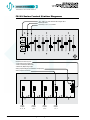
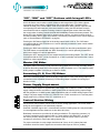
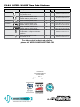
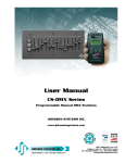
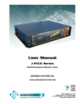
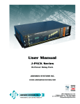
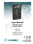
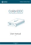
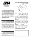
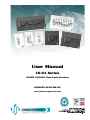
User Manual
CS-SA Series
'SUPER ANALOG' Time Fade Stations
JOHNSON SYSTEMS INC.
www.johnsonsystems.com
Contents
Warranty...........................................................................................................2
User Manual Copies.........................................................................................2
Introduction.......................................................................................................3
Features...........................................................................................................3
CS-SA Series Control Station Diagrams..........................................................4
“ON”, “DIM” and “OFF” Buttons with Integral LED’s.........................................5
Master (M) Slider..............................................................................................5
Secondary (3, 6, 9 or 12) Sliders......................................................................5
Power Supply Requirement..............................................................................5
Control Station Wiring......................................................................................5
Wiring an Independent Control Station............................................................6
Wiring a Single or Multiple Entrance Control Stations
to a Master Control Station...............................................................................6
Wiring Two or More Master Control Stations Together with “Take Control”......7
Wiring Two or More Control Stations Together with “Mimic”.............................7
Mounting the Control Station............................................................................8
Calibrate the Analog Output Voltage Level.......................................................8
Time Fade........................................................................................................9
Set the Adjustable Time Fade..........................................................................9
Set the Button LED Intensity............................................................................9
Local Lockout Mode Activation.......................................................................10
Remote Lockout Mode Activation...................................................................10
Short Circuit and Overload Protection............................................................10
Warranty
All CS-SA Series control stations come with a standard one (1) year limited
warranty against defects in parts and workmanship.
User Manual Copies
Additional copies of the most recent version of this manual can be
downloaded at:
http://www.johnsonsystems.com/pdf_files/jsi_cs_sa_manual_rev_1.pdf.
2
www.johnsonsystems.com
Introduction
Low voltage manual lighting controls for virtually any
application!
CS-SA Series
'SUPER ANALOG'
Time Fade Stations
The ‘Super Analog’ series of controls have been developed
specifically for control of LED fixtures and next generation fluorescent
ballasts requiring 0-10VDC analog control for dimming. Universal in
design this series of analog controls is designed to deliver unmatched
value in new or retrofit applications. ‘Super Analog’ controls are
a direct replacement for most Johnson Systems CS-2900 Series,
Electro Controls analog, Strand Microcontrol® and many other
commonly found analog controls.
Available from single to 12 channels with master, preset and take
control functions. These universal stations are designed to operate on
DC supply voltages up to 24 volts. Their output is digitally adjustable
from the station for exact control voltage requirements. Adjustable time
fade and LED intensity allow customization for demanding applications.
Durable powder-coat finish is available in either black or white.
Features
• Universal analog control stations for new or retrofit applications.
• Developed specifically for control of LED fixtures and next generation
fluorescent ballasts requiring 0-10VDC analog control for dimming.
• Direct replacements for most analog control stations.
• Seven models/sizes available including entrance stations.
• Digitally adjustable fade-times, voltage output and LED brightness.
• Electronic "take control" for multiple room/station applications.
• Multi-mode operation for remote/entrance station lockout.
• Short-circuit and over-current protection.
• Ruggedly built for reliability and longevity
• Tough, durable powder coat paint on 0.80” aluminum laser cut faceplate
for a scratch resistant non-glare finish.
• Color matched and sized for use with Johnson Systems AP Series
adapter plates where necessary to adapt to existing (larger) electrical
back boxes.
• Metal shaft sliders and machine screw mounting help prevent broken or
missing parts.
• Heavy-duty "high tactile" pushbutton switches are rated for 5 million
operations.
www.johnsonsystems.com
3
CS-SA Series Control Station Diagrams
"ON", "DIM", and "OFF" Buttons With Integral LED's
Master (M) Slider
Secondary (3, 6, 9, or 12) Sliders
6-Position Connector (J1) For:
• Power Supply Input (COM, V+)
• Button Contacts (ON, DIM, RST)
• Master Pot (MP) Analog Output
Analog Output Voltage Level Calibration Jumper (JP1)
Analog Output Connector(s)
OUTPUT
P1
P1
P1
P1
P2
P2
P2
P2
P3
P3
P3
P3
J1
Analog
Outputs
10, 11, 12
4
Analog
Outputs
7, 8, 9
Analog
Outputs
4, 5, 6
Analog
Outputs
1, 2, 3
www.johnsonsystems.com
CAL
JP1
“ON”, “DIM” and “OFF” Buttons with Integral LED’s
All CS-SA Series control stations contain 3 buttons with integral blue LED’s. When a button
is pressed, the control station is triggered into the corresponding state. The button LED’s
indicate the state of the control station. Under normal operation, when a button is pressed, the
corresponding LED will illuminate. If the control station is fading, the LED will flash once per
second until the fade is complete. Pressing a button or adjusting the master slider level while
the control station is fading, cancels the fade and immediately activates the button pressed. The
button LED’s also indicate when local or remote lockout is active, or if there is a short-circuit or
overload condition (refer to page 10 for details). The intensity of the button LED’s can be adjusted
(refer to “Set the Button LED Intensity” on page 9).
Pressing the “ON” button triggers all of the analog output levels to full on. The “ON” button
corresponds with the “ON” connection on J1 and is optionally connected to other control stations
for various applications.
Pressing the “DIM” button activates analog output control from the slider potentiometers (pots).
The “DIM” button corresponds with the “DIM” connection on J1 and is optionally connected to
other control stations for various applications.
Pressing the “OFF” button turns off (zero output level) all of the analog outputs. The “OFF” button
corresponds with the “RST” (reset) connection on J1 and is optionally connected to other control
stations for various applications.
Master (M) Slider
The master slider controls the overall maximum analog output level for all the secondary sliders,
as well as the analog output level on the master pot (MP) connection on J1. The master pot (MP)
analog output is capable of sourcing up to 50mA of current.
Secondary (3, 6, 9 or 12) Sliders
Each of the secondary sliders control the analog output level on each of the analog output (P#)
connections on the 3-position connector(s). Each analog output is capable of sourcing up to
50mA of current.
Power Supply Requirement
The control station requires a regulated DC power supply from 10.6VDC to 18VDC. The power
supply voltage should be a minimum of 2VDC greater than the required analog output voltage,
with the exception of 10.6VDC power supply applications with 0 to 10VDC analog output control
voltage. The power supply common (V-) connects to the “COM” connection on J1 and the power
supply positive (V+) connects to the “V+” connection on J1.
Control Station Wiring
CS-SA Series control stations can be wired for various analog applications. The control station
wiring can be configured for the functionality required.
Stranded, #18 AWG copper wire is recommended, however smaller gauge wire may be suitable
for some applications where distances are less than 150' (50m).
Breakaway connectors are provided for all wiring terminations. The 6-position connector (J1)
is used to connect the power supply (COM, V+), three switches (ON, DIM, RST), as well as
the master pot (MP) analog output. For 3, 6, 9 and 12 channel control stations, 3-position
connector(s) are used to connect the analog outputs (P#).
For proper termination, the strip length should be 0.28" (7mm). A 1/8" (3.2mm) flat head
screwdriver should be used to tighten the connections and torque to 3.5Lb-In (0.4Nm).
www.johnsonsystems.com
5
Wiring an Independent Control Station
An independent control station requires 2 conductors for V+ and common, and 1, 3, 6, 9 or 12
conductors for the analog outputs.
CS-SA-12
CS-SA-1
COM
V+
DC POWER SUPPLY
POSITIVE (V+) INPUT
P12 (P3)
P11 (P2)
P10 (P1)
P9 (P3)
P8 (P2)
P7 (P1)
P6 (P3)
P5 (P2)
P4 (P1)
P3
P2
P1
V+
CS-SA-ENT2B
DC POWER SUPPLY
COMMON (V-) INPUT
COM
DC POWER SUPPLY
COMMON (V-) INPUT
DC POWER SUPPLY
POSITIVE (V+) INPUT
MP
ANALOG OUTPUT
COM
V+
MP
DC POWER SUPPLY
COMMON (V-) INPUT
DC POWER SUPPLY
POSITIVE (V+) INPUT
ANALOG OUTPUT
ANALOG OUTPUTS
Wiring a Single or Multiple Entrance Control Stations
to a Master Control Station
An entrance control station (Part Numbers: CS-SA-ENT2B and CS-SA-ENT3B) is typically
installed at an entrance location and used to trigger a master control station into the “ON”, “DIM”
or “OFF” state. The entrance station(s) and master station mimic each other when a button
is pressed. Wiring between a single or multiple entrance stations and master station requires
2 conductors for V+ and common, and 3 conductors for the switches (ON, DIM and RST),
1 conductor for each switch function.
CS-SA-ENT3B
CS-SA-12
COM
V+
ON
DIM
RST
COM
6
P12 (P3)
P11 (P2)
P10 (P1)
P9 (P3)
P8 (P2)
P7 (P1)
P6 (P3)
P5 (P2)
DC POWER SUPPLY
POSITIVE (V+) INPUT
ANALOG OUTPUTS
COM
COM
V+
ON
RST
www.johnsonsystems.com
P12 (P3)
P11 (P2)
P10 (P1)
P9 (P3)
P8 (P2)
P7 (P1)
P6 (P3)
V+
P5 (P2)
COM
V+
ON
RST
P4 (P1)
COM
V+
ON
RST
DC POWER SUPPLY
COMMON (V-) INPUT
CS-SA-12
P1
COM
V+
ON
RST
CS-SA-ENT2B
P3
CS-SA-ENT2B
P4 (P1)
V+
P3
COM
V+
ON
DIM
RST
P2
COM
V+
ON
DIM
RST
P1
COM
V+
ON
DIM
RST
P2
CS-SA-ENT3B
DC POWER SUPPLY
COMMON (V-) INPUT
DC POWER SUPPLY
POSITIVE (V+) INPUT
ANALOG OUTPUTS
Wiring Two or More Master Control Stations
Together with “Take Control”
When two or more master control stations are controlling the same device, “take control”
is typically required. When a button is pressed on one of the master control stations, it will
automatically “take control” from the other master control stations and put them in the “OFF”
state. Wiring between the master control stations requires 2 conductors for V+ and common,
and 1 conductor for reset (RST) “take control”.
CS-SA-12
CS-SA-12
COM
COM
V+
RST
DC POWER SUPPLY
COMMON (V-) INPUT
DC POWER SUPPLY
POSITIVE (V+) INPUT
P12 (P3)
P11 (P2)
P10 (P1)
P9 (P3)
P8 (P2)
P7 (P1)
P6 (P3)
P5 (P2)
P4 (P1)
P3
P2
V+
P1
P12 (P3)
P11 (P2)
P10 (P1)
P9 (P3)
P8 (P2)
P7 (P1)
P6 (P3)
P5 (P2)
P4 (P1)
P3
P2
P1
COM
V+
RST
ANALOG OUTPUTS
CS-SA-1
COM
V+
RST
MP
COM
V+
RST
MP
CS-SA-1
DC POWER SUPPLY
COMMON (V-) INPUT
COM
V+
DC POWER SUPPLY
POSITIVE (V+) INPUT
MP
ANALOG OUTPUT
Wiring Two or More Control Stations
Together with “Mimic”
“Mimic” refers to pressing a button (“ON”, “DIM” or “OFF”) on a control station, and the other
control station(s) are automatically triggered into the same “ON”, “DIM” or “OFF” state. The
analog output(s) could be controlling the same device or completely different device. Wiring
between the control stations requires 2 conductors for V+ and common, and 3 conductors (2
conductors for Part Number: CS-SA-ENT2B) for the switches (ON, DIM and RST), 1 conductor
for each switch function.
CS-SA-ENT2B
COM
V+
ON
RST
CS-SA-12
COM
V+
ON
DIM
RST
COM
CS-SA-ENT2B
COM
COM
V+
ON
RST
V+
MP
www.johnsonsystems.com
P12 (P3)
P11 (P2)
P10 (P1)
P9 (P3)
P8 (P2)
P7 (P1)
P6 (P3)
P5 (P2)
P4 (P1)
P3
V+
P2
ANALOG
OUTPUTS
P1
P12 (P3)
P11 (P2)
P10 (P1)
COM
V+
ON
DIM
RST
P9 (P3)
P8 (P2)
P7 (P1)
P6 (P3)
P5 (P2)
P4 (P1)
P3
P2
P1
CS-SA-12
DC POWER SUPPLY
COMMON (V-) INPUT
DC POWER SUPPLY
POSITIVE (V+) INPUT
ANALOG
OUTPUTS
DC POWER SUPPLY
COMMON (V-) INPUT
DC POWER SUPPLY
POSITIVE (V+) INPUT
ANALOG OUTPUT
7
Mounting the Control Station
The control station can be mounted on/in a gangable (usually masonry) type of back box
with a minimum depth of 2" (50.8mm) and a preferred depth of 3.5” (88.9mm). A #2 Phillips
head screwdriver is required to secure the control station, using the provided black #6-32 x 1"
(25.4mm) mounting screws.
NOTE: Ensure the back box is earth grounded to protect the control station from electrostatic
discharge.
NOTE: Ensure the back box mounting-hole threads are not damaged. Damaged threads on the
back box can damage the threads on the mounting screws and cause stripping. The back
box threads can quickly be cleaned up by running a #6-32 tap through the mounting hole.
Be sure not to over-tighten the mounting screws or this could result in stripping the back
box mounting-hole threads.
NOTE: For applications other than 0 to 10VDC analog output control, the analog output voltage
needs to be calibrated before the control station is mounted. See below for details.
NORMAL
RUN
MODE
OUTPUT CAL
JP1
Calibrate the Analog Output Voltage Level
Calibration of the analog output voltage should be completed at the time of installation. The analog
output may need to be calibrated for line loss or to change the analog output voltage range.
The analog output voltage can be calibrated/adjusted for analog control over a range from
0 to 22VDC (24VDC power supply) in 12-bit step resolution for precise control and calibration.
The analog output voltage is factory set for 0 to 10VDC control.
JUMPER
OUTPUT
CALIBRATION
MODE
OUTPUT CAL
JP1
JUMPER
Ensure the power supply voltage is a minimum of 2VDC greater than the required analog output
voltage.
Procedure:
•
•
•
•
Set the output calibration (OUTPUT CAL) jumper (JP1) in the left-hand side position.
Set the master slider potentiometer (pot) in the full on position (all the way up).
Measure the DC voltage between common (COM) and the master pot (MP) output.
Press the “ON” button to increase the analog output voltage. The “ON” LED illuminates when
the button is pressed. Press and hold the “ON” button to accelerate the voltage adjustment.
• Press the “OFF” button to decrease the analog output voltage. The “OFF” LED illuminates
when the button is pressed. Press and hold the “OFF” button to accelerate the voltage
adjustment.
• Pressing the “ON” and “OFF” buttons at the same time adjusts the output voltage to
approximately 10VDC.
• Once the required output voltage has been measured, set the output calibration jumper back
in the right-hand side position to exit calibration mode and save the calibration setting.
NOTE: The control station will go into overload protection (all button LED’s flash on and off) if the
output voltage calibration is set higher than the power supply input voltage. If this occurs,
recalibrate the output voltage to a lower voltage. Ensure the power supply voltage is a
minimum of 2VDC greater than the required analog output voltage.
8
www.johnsonsystems.com
Time Fade
The control station is capable of fading from:
“OFF”
“ON”
“ON”
“OFF”
“OFF”
“DIM”
“DIM”
“OFF”
The control station is capable of pseudo fading from:
“DIM”
“ON”
“ON”
“DIM”
The control station automatically begins fading when a button is pressed. The button LED flashes
on and off once per second to indicate fading.
NOTE: Pressing a button or adjusting the master slider level while the control station is fading,
cancels the fade and immediately activates the button pressed.
Set the Adjustable Time Fade
The time fade can be adjusted from 0 to 60 seconds. The factory default time fade is 5 seconds.
NOTE: Be sure the local and remote lockout modes are deactivated before adjusting the time fade.
Procedure:
• To set the adjustable time fade, press and hold the “ON” button for approximately 10
seconds, until the “ON” LED extinguishes.
• Release the “ON” button and count the number of times the “ON” LED flashes on. Each time
the “ON” LED flashes on, 1 second of time fade is represented.
• Once the required number of times the “ON” LED flashes on is counted, press the “ON”
button to save the time fade and exit.
• To set the time fade to zero (no fading), press and hold the “ON” button for approximately
10 seconds, until the “ON” LED extinguishes. Release the “ON” button and immediately
press the “ON” button again before the “ON” LED flashes on.
Set the Button LED Intensity
The button LED intensity can be adjusted to a preferred intensity level for various environments.
NOTE: Be sure the local and remote lockout modes are deactivated before adjusting the button
LED intensity.
Procedure:
• To enter the button LED intensity adjust mode, press and hold the “ON” and “OFF” buttons
at the same time for approximately 10 seconds, until all the button LED’s illuminate.
• Press the “ON” button to increase the button LED intensity. Press and hold the “ON” button
to accelerate the intensity adjustment.
• Press the “OFF” button to decrease the button LED intensity. Press and hold the “OFF”
button to accelerate the intensity adjustment.
• Once the preferred button LED intensity has been set, press the “ON” and “OFF” buttons
at the same time to exit the button LED intensity adjust mode and save the setting.
NOTE: There is a minimum button LED intensity so the control station will always indicate its
mode of operation/state.
www.johnsonsystems.com
9
Local Lockout Mode Activation
When the local lockout mode is activated, the control station is locked in the “OFF” state. Any
button press is ignored and the “OFF” LED flashes once to indicate local lockout mode is
activated.
Procedure:
• To activate the local lockout mode, press and hold the “OFF” button for approximately
10 seconds, until the “OFF” LED extinguishes.
• To deactivate the local lockout mode, press and hold the “OFF” button for approximately
10 seconds, until the “OFF” LED illuminates.
Remote Lockout Mode Activation
When the remote lockout mode is activated, the control station ignores all remote control station
key presses. The active LED flashes off for 0.1 seconds every 2 seconds to indicate remote
lockout mode is activated.
Procedure:
• To activate the remote lockout mode, press and hold the “DIM” button for approximately
10 seconds, until the “DIM” LED flashes off for 0.1 seconds.
• To deactivate the remote lockout mode, press and hold the “DIM” button for approximately
10 seconds, until the “DIM” LED flashes off for 0.1 seconds.
Short Circuit and Overload Protection
The control station is equipped with short circuit and overload protection. The short circuit limit is
set at 100mA with 0.6W of power dissipation. When a short circuit or overload is detected while in
the “ON” or “DIM” state, all of the button LED’s flash on and off to indicate there is a short circuit
or overload condition. The control station automatically recovers to normal operational state once
the short circuit or overload is removed.
10
www.johnsonsystems.com
Notes
www.johnsonsystems.com
11
CS-SA 'SUPER ANALOG' Time Fade Stations
Model
Description
# Wires
Back
Box
Minimum PCB Clearance
CS-SA-1-?
1 gang, single channel manual control
w/on, present, and off
4
1 gang
1.80" W x 2.75" H x 2.00" D
4.6 cm x 7.0 cm x 5.1 cm
CS-SA-3-?
2 gang, 3 channel manual control
w/master slider, on, preset, and off
6
2 gang
3.60" W x 2.75" H x 2.00" D
9.1 cm x 7.0 cm x 5.1 cm
CS-SA-6-?
3 gang, 6 channel manual control
w/master slider, on, preset, and off
9
3 gang
5.50" W x 2.75" H x 2.00" D
14.0 cm x 7.0 cm x 5.1 cm
CS-SA-9-?
4 gang, 9 channel manual control
w/master slider, on, preset, and off
12
4 gang
7.30" W x 2.75" H x 2.00" D
18.5 cm x 7.0 cm x 5.1 cm
CS-SA-12-?
5 gang, 12 channel manual control
w/master slider, on, preset, and off
15
5 gang
9.10" W x 2.75" H x 2.00" D
23.1 cm x 7.0 cm x 5.1 cm
CS-SA-ENT2B-?
1 gang, 2 button (on/off) entrance station
with adjustable “on” voltage for stand-alone
applications
5
1 gang
1.80" W x 2.75" H x 2.00" D
4.6 cm x 7.0 cm x 5.1 cm
CS-SA-ENT3B-?
1 gang, 3 button entrance station
w/on, preset, and off
6
1 gang
1.80" W x 2.75" H x 2.00" D
4.6 cm x 7.0 cm x 5.1 cm
For other control products and solutions
please visit WWW.JOHNSONSYSTEMS.COM
User Manual
CS-SA 'SUPER ANALOG'
Time Fade Stations
Rev. 1
www.johnsonsystems.com