1
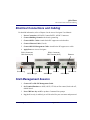
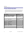
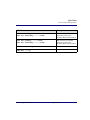
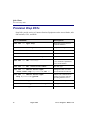
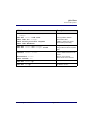
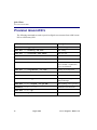
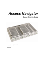
Access Navigator
QUICK START GUIDE
Document Number: 002-0108-0500
Product Release: 1.8
August 2003
Copyright 2003 Carrier Access Corporation. All rights reserved.
The information presented in this manual is subject to change without notice and does not represent
a commitment on the part of Carrier Access Corporation. The hardware and software described
herein are furnished under a license or non-disclosure agreement. The hardware, software, and
manual may be used or copied only in accordance with the terms of this agreement. It is against the
law to reproduce, transmit, transcribe, store in a retrieval system, or translate into any medium –
electronic, mechanical, magnetic, optical, chemical, manual, or otherwise – any part of this manual
or software supplied with the Access Navigator for any purpose other than the purchaser’s personal
use without the express written permission of Carrier Access Corporation.
Access Navigator, Access Bank, Adit, and the Carrier Access Logo are registered trademarks of
Carrier Access Corporation. All other brand or product names are trademarks or registration
trademarks of their respective companies or organizations.
Contact Information:
Carrier Access Corporation
5395 Pearl Parkway
Boulder, CO 80301-2490
Corporate Phone: (800) 495-5455
Fax: (303) 443-5908
www.carrieraccess.com
Customer Support Direct: (800) 786-9929
E-mail: [email protected]
QUICK START GUIDE
Quick Start Guide
In this Guide
n
Overview ... 4
n
Physical Installation ... 4
n
Electrical Connections and Cabling ... 5
n
Current Status and Settings ... 8
n
Provision Access Navigator ... 9
n
Provision GR-303 Switch DS1s ... 10
n
Provision Drop DS1s ... 12
n
Provision Groom DS1s ... 14
n
Provision Remote Access Bank II ... 15
n
Application Configuration Requirements ... 17
n
Useful Maintenance Commands ... 18
n
Alarm and Status Indicators ... 21
Quick Start
Overview
Overview
This Access Navigator® Quick Start Guide is intended for experienced installers and users
who do not need the detailed installation and setup instructions provided in the User
Manual. For detailed information and instructions, refer to the following chapters in the
User Manual, included on the CD-ROM disk in the shipping box.
l
l
l
l
l
l
l
l
l
l
l
l
Chapters 2, 3, 4 – Product Descriptions and Specifications
Chapter 5 – Physical Installation
Chapter 6 – Electrical Installation
Chapter 8 – Provision Access Navigator
Chapter 9 – Provision DCS Service
Chapter 10 – Provision GR-303 Service
Chapter 11, 12, 13 – Provision Remote Access Bank II and Adit 600
Chapter 14 – Alarm Clearing
Chapter 15 – Diagnostics and Troubleshooting
Chapter 16 – Maintenance Procedures
Chapter 17 – Update Controller Card Software
Chapter 18 – CLI Language Reference
Physical Installation
Ensure adequate clearance and spacing for thermal cooling. For detailed information, refer
to Chapter 5 in the Access Navigator User Manual.
• Horizontal 19-Inch and 23-Inch Rack Mount. Provide at least 4.37 inches (2.5
rack units) of free air space above and below chassis for air circulation.
• Vertical Rack Mount Using Crossbars. Provide at least 0.75 inch of free air
space on left and right side of chassis for air circulation.
• Vertical Wall Mount. Wall mounting is approved only for customer premises.
The Access Navigator requires free air space on top, bottom, and ends of chassis
for air circulation. Refer to detailed information in Chapter 5.
4
August 2003
Access Navigator - Release 1.8
Quick Start
Electrical Connections and Cabling
Electrical Connections and Cabling
For detailed information, refer to Chapter 6 in the Access Navigator User Manual.
1. Power Connection. ALWAYS Connect BOTH –48VDC Connectors.
2. Connect Building Ground to the chassis ground lug.
3. Connect DSX-1 Cables. Attach ferrite RF suppressors to both cables.
4. Connect Ethernet Cable (if used).
5. Connect RS-232 Management Cable. Attach ferrite RF suppressor to cable.
6. Apply Power to Access Navigator.
DSX-1 Connector
DS1 Receive (IN)
Ground Lug
DSX-1 Connector
DS1 Transmit (OUT)
Alarm Out
Alarm In
BITS Timing In
–48V B Input
Ethernet
RS-232 CLI
–48V A Input
Start Management Session
1. Connect PC to RS-232 Management Cable.
2. Set Terminal Emulator to ANSI, ASCII, VT100, no flow control, local echo off,
9600/8/None/1.
3. Press CR/Enter key on PC to produce Command Line prompt.
4. Log In. If security is enabled, you will be asked for your user name and password.
Access Navigator - Release 1.8
August 2003
5
Quick Start
Using the Command Line Interface (CLI)
Using the Command Line Interface (CLI)
Online Help
Online help for CLI commands is available any time you are logged into the Access
Navigator. You can display basic commands and obtain context sensitive help with
additional detail.
To display a list of basic CLI commands, just type a question mark (?). You can also
type the word help and press the Enter or Return key on the terminal.
Help for a specific CLI command is available by typing help before the command word
or words in the partial command pressing the Enter or Return key. It is usually easier
to type a question mark (?) after the partial command. The partial command will be
repeated so that you can easily add the next value or key word.
Context sensitive help does not work for command words taken out of context.
Text Conventions
Input commands and keywords in this guide appear in a bold typewriter font, as in the
following example.
set ds1 1-4 up
If a command requires you to enter additional information, an italic typewriter font is
used to show what item or items are required. Each item will be enclosed in < >
symbols, as in the following example requesting a number n and a setting value. Do not
type the < > symbols.
set ds1 <n> <setting>
If you must enter one item from a list, the items will be separated by vertical lines, as
in the following example request you to select either up or down. Do not type the
< | > symbols.
set ds1 <n> <up|down>
Online help does not use italic or bold type.
6
August 2003
Access Navigator - Release 1.8
Quick Start
Using the Command Line Interface (CLI)
Entering DS1 and DS0 Numbers and Ranges
Commands containing ds1 <n> require you to enter a DS1 number (1 to 32) or a
range of DS1 numbers. For example, DS1 #6 is entered as ds1 6. To enter a range of
DS1s, type the starting and ending numbers, separated by a hyphen. For example, DS1s
#1 through #8 can be specified by typing ds1 1-8.
Commands containing ds0 <n:ch> require you to enter a DS1 number (1 to 32)
and DS0 number (1 to 24) separated by a colon. For example, the channel list for DS1
#4 and DS0 channel #8 would be entered as ds0 4:8. The channel list may also
contain a range of DS0 channels. For example, DS1 #6 and DS0 channels #1 through
#12 would be entered as ds0 6:1-12. A colon follows the DS1 number, and the
beginning and ending DS0 channels are separated by a hyphen.
Command Shortcuts (Tabbing)
“Tabbing” is a shortcut for typing commands. CLI allows the user to enter partial
command fragments, then press the Tab key.
For example, if you type stat equip or just st eq and press the Tab key, the CLI
will respond with status equipment. If this is correct, press the Enter or Return
key to execute the command. For corrections, use the Backspace, Delete, and Escape
keys.
You can “Tab” after typing each fragment or after typing a series of fragments. The CLI
will re-echo the command each time you press the Tab key. When you are satisfied that
the command is correct, press the Enter or Return key.
Tabbing will not substitute a word that does not represent a valid command or attempt
to correct numbers (such as 9:1-8) or strings enclosed in quotes (such as
“AcmeCorp”).
Keyboard Shortcuts
l
l
l
Ctrl F
Ctrl R
Esc
Forward – displays next command line.
Reverse – displays previous command line.
Escape – cancel CLI command without entering.
Access Navigator - Release 1.8
August 2003
7
Quick Start
Current Status and Settings
Current Status and Settings
8
CLI Commands
Descriptions
status equipment
Show equipment configuration.
show ds1 <n|all>
show ds0 <n:ch>
show isdn crv <range>
show isdn database
status ds1 <n>
status ds0 <n:ch>
Show service status.
set ds1 <n> down
set ds0 <n:ch> down
set ds0 <n:ch> type <voice|data>
Set unused circuits out of service
(down). If the DS1 is not
terminated, set the DS0 type of
all channels to data. If the DS1 is
terminated, set the DS0 type of
any unused channels to match the
DS0 type (voice or data)
configured on the device at the
other end of the DS1.
August 2003
Access Navigator - Release 1.8
Quick Start
Provision Access Navigator
Provision Access Navigator
Use the following commands to set up the Access Navigator for network operation and
remote management.
CLI Commands
Descriptions
set id <"id">
System Identifier or CLLI code
set date <mm/dd/yyyy>
set time <hh:mm:ss>
Date with four-digit year.
Time with 24-hour clock.
DCS units must be set manually
but GR-303 units can be set by
end office switch via EOC.
set ethernet ip address none
Disable Ethernet interface if not
used.
Enable Ethernet interface.
set ethernet ip address <address>
<mask>
set ip gateway <address>
add user <name>
set user <name> level <access>
set user <name> password
delete user <name>
Access Navigator - Release 1.8
IP gateway address
Add user name.
Access level, 1 to 3.
Password.
Remove user.
August 2003
9
Quick Start
Provision GR-303 Switch DS1s
Provision GR-303 Switch DS1s
Any DS1 port may be defined as a Switch, Drop, or Groom. Switch DS1s connect to the
end office switch for GR-303 operation. To ensure that calls are processed properly, the
Terminal ID, EOC, and TMC settings must match those in the end office switch. It is
prudent to assign the Primary and Secondary Switch DS1s to different Quad T1 Framer
cards.
CLI Commands
Descriptions
set switch type <5ess|dms|generic>
Ensures switch compatibility.
set clock1 <bits|ds1 n|internal>
set clock2 <bits|ds1 n|internal>
Primary and Secondary system
clock sources. BITS is
recommended where available or
where transport to the end office
switch is via a SONET network.
set ds1 <n> type switch
Switch DS1 type for GR-303
interface group.
set ds1 <n> framing esf
Switch DS1 framing for switch.
set ds1 <n> linecode b8zs
Switch DS1 line code.
set ds1 <n> id <"id">
Switch DS1 identifier.
set ds1 <n> termid <id>
Switch DS1 terminal identifier.
set ds1 <n> clock normal
DS1 transmit clock source.
set ds1 <n> lbo <setting>
DS1 line buildout. Use settings
1 to 5 for DSX-1 equalization.
set ds1 <n> loopdetect <on|off>
Usually off for drop DS1s.
set ds1 <n> fdl none
Switch DS1 FDL is always none.
10
August 2003
Access Navigator - Release 1.8
Quick Start
Provision GR-303 Switch DS1s
CLI Commands
Descriptions
set eoc primary <n:ch|none>
set eoc secondary <n:ch|none>
EOC channels are normally
assigned to primary and
secondary DS1s and use DS0 12.
set tmc primary <n:ch|none>
set tmc secondary <n:ch|none>
TMC channels are normally
assigned to primary and
secondary DS1s and use DS0 24.
set ds0 <n:ch> up
Set DS0s in service.
set ds1 <n> up
Set DS1s in service.
Access Navigator - Release 1.8
August 2003
11
Quick Start
Provision Drop DS1s
Provision Drop DS1s
Drop DS1s provide service to Customer Premises Equipment such as Access Banks, Adit
600 terminals, CSUs, and PBXs.
CLI Commands
Descriptions
set ds1 <n> type drop
Drop DS1 type for service to
Customer Premises.
set ds1 <n> framing <d4|esf|slc96>
Drop DS1 framing.
set ds1 <n> linecode <ami|b8zs>
DS1 line code.
set ds1 <n> id <"id">
DS1 identifier.
set ds1 <n> clock <normal|loop>
DS1 transmit clock source.
set ds1 <n> lbo <setting>
DS1 line buildout, 1 to 9.
1 to 5 for DSX-1 equalization,
6 to 9 for attenuation.
set ds1 <n> fdl <none|slc96|t1403>
DS1 FDL type
set ds1 <n> remote device mgmt
<none|cafdl|caip <ipaddress>|ds1 n>
Management link for remote
Access Bank II and Adit 600.
set ds1 <n> remote device mgmt
caip <ipaddress> pphone
Enables call communications
channel for remote Adit 600
providing P-Phone service.
set ds1 <n> loopdetect <on|off>
Usually off for drop DS1s.
set ds0 <n:ch> type <voice|data|gr303>
DS0 type.
set ds0 <n:ch> pphone
P-Phone channels.
12
August 2003
Access Navigator - Release 1.8
Quick Start
Provision Drop DS1s
CLI Commands
Descriptions
set ds0 <n:ch> isdn <b1|b2|d> crv
<range>
set ds0 <n:ch> isdn none
show isdn crv <range>
send switch provision request
show isdn database
ISDN BRI 4:1 TDM channels.
set ds0 <n:ch> crv <range>
set ds0 <n:ch> crv <range> slc96
Assign CRVs in sequential order.
Assign CRVs in odd-even (slc96)
order.
connect <n:ch> <n:ch>
disconnect <n:ch>
show connect <n>
Connect ISDN D channel to the
switch.
Remove cross-connect.
Show current cross-connects.
set ds0 <n:ch> up
Set DS0s in service.
set ds1 <n> up
Set DS1s in service.
Access Navigator - Release 1.8
Unassign ISDN channels.
Show ISDN CRVs.
If RDT is enabled on Switch.
Show ISDN provisioning.
August 2003
13
Quick Start
Provision Groom DS1s
Provision Groom DS1s
The following commands are used to provision digital cross-connects from a DS0 on one
DS1 to a DS0 on any DS1.
CLI Commands
Descriptions
set ds1 <n> type groom
Groom DS1 type.
set ds1 <n> framing <d4|esf>
DS1 framing.
set ds1 <n> linecode <ami|b8zs>
DS1 line code.
set ds1 <n> id <"id">
DS1 identifier.
set ds1 <n> clock <normal|loop>
DS1 transmit clock source.
set ds1 <n> lbo <setting>
DS1 line buildout, 1 to 9.
1 to 5 for DSX-1 equalization,
6 to 9 for attenuation.
set ds1 <n> loopdetect <on|off>
Usually off for drop DS1s.
show connect <n>
Show DS0 crossconnections.
disconnect <n:ch>
Remove old DS0 connections.
set ds0 <n:ch> type <voice|data>
DS0 type (use data type for ISDN
PRI passthrough).
set ds0 <n:ch> signal <ls|gs|em>
DS0 signaling (voice type only).
connect <n:ch> <n:ch>
Add DS0 crossconnections.
set ds0 <n:ch> up
Set DS0s in service.
set ds1 <n> up
Set DS1s in service.
14
August 2003
Access Navigator - Release 1.8
Quick Start
Provision Remote Access Bank II
Provision Remote Access Bank II
Use the online help to display available settings.
CLI Commands
Descriptions
set remote <n> config off
Temporarily disable
configuration downloading to
remote Access Bank II.
set
set
set
set
set
set
set
set
ds1 <n> type drop
ds1 <n> framing esf
ds1 <n> linecode b8zs
ds1 <n> remote mgmt cafdl
ds1 <n> lbo <setting>
ds1 <n> loopdetect off
ds1 <n> id <"name">
remote <n> id <"name">
Provision DS1 service to remote,
including remote management
interface.
set
set
set
set
ds0
ds0
ds0
ds0
Provision DS0 service to remote.
<n:ch>
<n:ch>
<n:ch>
<n:ch>
type <setting>
signaling <setting>
crv <setting>
up
connect <n:ch> <n:ch>
disconnect <n:ch>
Provision DCS crossconnects to
remote.
read
read
read
read
read
Read remote DS0 connections
and interface settings.
remote
remote
remote
remote
remote
<n>
<n>
<n>
<n>
<n>
connections
rs232
t1
t1drop
v35
Note: SDSL interface port has no
settings to read.
add interface <"name"> <n:ch>
Create fractional interface and
assign DS0s to be used.
set remote <n> rs232 <setting>
set remote <n> t1drop <setting>
set remote <n> v35 <setting>
Configure remote interface port
to meet customer requirements.
Access Navigator - Release 1.8
August 2003
15
Quick Start
Provision Remote Access Bank II
CLI Commands
Descriptions
connect remote <"name"> <port>
disconnect remote <"name">
Connect fractional interface to
remote interface port.
set remote <n> config on
Download configuration.
set ds0 <n:ch> up
Set DS0s in service.
set ds1 <n> up
Set DS1s in service.
16
August 2003
Access Navigator - Release 1.8
Quick Start
Application Configuration Requirements
Application Configuration Requirements
Permissible Selections
Application
DS1
Type
DS1
Framing
DS1 Line
Code
DS1
FDL
Remote
Mgmt
Voice to GR-303 switch
Switch
ESF
B8ZS
None
None
Voice or data to DCS switch
Groom
D4 or ESF
AMI or
B8ZS
None
None
Voice or data to subscriber drop
Drop
D4
AMI or
B8ZS
None
None
Voice or data to subscriber drop
Drop
ESF
AMI or
B8ZS
None or
T1403
None
Adit 600 TDM (FDL mgmt)
(controller management DS1)
Drop
ESF
B8ZS
None
CA FDL
Adit 600 TDM (FDL mgmt)
(all other DS1s point to controller
management DS1)
Drop
ESF
B8ZS
None
DS1 <n>
Adit 600 TDM (IP mgmt)
(controller management DS1)
Drop
D4 or ESF
B8ZS
None
CA IP
Adit 600 TDM (IP mgmt)
(all other DS1s point to controller
management DS1)
Drop
D4 or ESF
B8ZS
None
DS1 <n>
Access Bank II
(not remotely provisioned)
Drop
D4 or ESF
AMI or
B8ZS
None
None
Access Bank II
(remotely provisioned)
Drop
ESF
B8ZS
None
CA FDL
Access Bank I/TR-08 or
SLC-96/TR-08 (Shelf A)
Drop
SLC96
AMI or
B8ZS
SLC96
None
SLC-96/TR-08
(Shelf B, C, D)
Drop
SLC96
AMI or
B8ZS
None
None
Access Navigator - Release 1.8
August 2003
17
Quick Start
Useful Maintenance Commands
Useful Maintenance Commands
Category
CLI Commands
Context-sensitive help available
at any time.
help
?
Alarm Cut-Off.
aco
Display configuration settings.
show autoexit
show clock
show connect
show crv <range>
show date
show ds0 <n:ch>
show ds1 <n|all>
show eoc
show ethernet
show id
show interface <"name"|all>
show ip
show isdn crv <range>
show remote <n|all>
show remote <n> connections
show snmp
show switch
show time
show tmc
show users
whoami
Read remote Access Bank II
DS0 connections and interface
settings.
read
read
read
read
read
read
Note: SDSL interface port has no
settings to read.
18
August 2003
remote
remote
remote
remote
remote
remote
<n>
<n>
<n>
<n>
<n>
<n>
connections
rs232
t1
t1drop
v35
alarms
Access Navigator - Release 1.8
Quick Start
Useful Maintenance Commands
Category
CLI Commands
Display current information
about an interface.
status
status
status
status
status
status
status
status
Check IP connectivity.
ping <ipaddr>
Display all alarms.
Display selected alarms.
alarms
alarms <major|minor|alert>
Display all log events except
BERT, TMC, and Configuration
change events.
Display selected logs.
log
Access Navigator - Release 1.8
log
log
log
log
log
log
log
log
log
log
log
log
log
log
log
clock
crv <range>
ds0 <n:ch>
ds1 <n|all>
ds1 <n> performance
ds1 <n> performance history
eoc
equipment
<major|minor|alert|info>
ds1 <n>
ds1 <n> <major|minor|alert|info>
equipment
equipment <major|minor|alert|info>
info
bert
config
config ds0 <n:ch>
config ds1 <n>
config crv <value>
config source <cli|eoc|snmp|icc>
tmc
tmc permanent
tmc crv <value>
August 2003
19
Quick Start
Useful Maintenance Commands
Category
CLI Commands
Clear logs.
clear
clear
clear
clear
clear
clear
clear
clear
clear
Controller switch.
Reset both Controllers.
Reset only standby Controller.
Reset a DS1 framer.
Reset remote Access Bank II.
switch controller
reset all
reset standby
reset ds1 <n>
reset remote <n>
Restore factory defaults.
restore defaults
Test alarm functions and produce
alarm messages.
set alarms <critical|major|minor>
<on|off>
Test DS1 circuits with
loopbacks.
send
send
send
send
send
Send test pattern.
Turn off test pattern.
send ds1 <n> line
<p2e11|p2e15|p2e23|qrss>
send ds1 <n> payload <allones|allzeros
|f1in8|p2e11|p2e15|p2e23|qrss>
send ds1 <n> off
Perform automatic BER test and
display test result.
Note: Test pattern will turn off
when test is complete.
send ds1 <n> line
<p2e11|p2e15|p2e23|qrss> test
send ds1 <n> payload <allones|allzeros
|f1in8|p2e11|p2e15|p2e23|qrss> test
20
August 2003
bert log
blocked call count
config log
ds1 <n> performance
log
peak call count
permanent call count
remote <n> log
tmc log
ds1
ds1
ds1
ds1
ds1
<n>
<n>
<n>
<n>
<n>
csu <loopup|loopdown>
line <loopup|loopdown>
network <loopup|loopdown>
niu <loopup|loopdown>
payload <loopup|loopdown>
Access Navigator - Release 1.8
Quick Start
Alarm and Status Indicators
Alarm and Status Indicators
For alarm clearing producers and detailed indicator descriptions, see Chapters 14 and 15 in
the Access Navigator User Manual.
Normal LED states are shown in Boldface type.
LED
State
Description
Power
(Two LEDs, one for
each Controller card)
Off
Red
Yellow
Green
-48V power failure.
Internal power supply failure.
Card is booting up.
Normal operation.
Active (Controller)
Off
Green
Yellow
Controller card is standby.
Controller card is active.
Insufficient memory. SIMM (memory module)
is required.
Critical Alarm
Off
Red
No critical alarms present.
Critical alarm exists.
Major Alarm
Off
Red
No major alarms present.
Major alarm exists.
Minor Alarm
Off
Yellow
No minor alarms present.
Minor alarm exists.
ACO (alarm cut-off)
Off
Yellow
Alarm(s) active.
Alarm(s) suppressed.
DS1 Status
Off
Red
Red Flashing Slow
Red Flashing Fast
Yellow
Yellow Flashing
Green
Green Flashing
Off-line.
Loss of signal (LOS).
Out of frame or AIS.
Self-test failure.
Lince code violation (LCV).
Yellow alarm.
Normal operation.
Loopback test in progress.
Off
Green
No link or connection.
Normal operation.
(Each Quad T1 Framer
card has four LEDs)
Ethernet
(on rear panel)
Access Navigator - Release 1.8
August 2003
21
Quick Start
Alarm and Status Indicators
22
August 2003
Access Navigator - Release 1.8