1
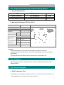
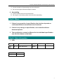
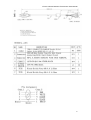
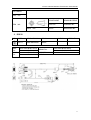
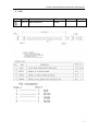
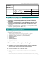
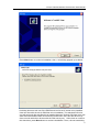
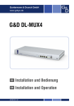
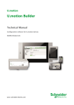
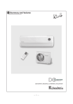
VTouch 5-Wires Resistive Touchscreen User Manual
VTOUCH touchscreen
VT and VTT series
Your Distributor:
Novo-Parts Kft. Hungary
www.novoparts.hu
Part Number:
VR-151-03-V11
Description:
5 Wires Resistive Touch Screen
1
VTouch 5-Wires Resistive Touchscreen User Manual
5-Wire Resistive Touch Screen
Index
Part 1. Features & Technical Specification ..................................... 3
Part 2. Mechanical Drawings and Connection Sketch..................... 5
Part 3. Optical .............................................................................. 5
Part 4. Environmental................................................................... 5
Part 5. Electrical........................................................................... 7
Part 6. Cosmetic Quality ............................................................... 8
Part 7. Cautions............................................................................ 8
Part 8. Others ............................................................................... 9
Part 9. Cable Information ............................................................. 9
Part 10. Integration Procedure .................................................... 14
Part 11. Install Touch System Driver ........................................... 14
Part 12. How to Test the 5-Wires Resistive Touchscreen ............... 18
VTouch 5-Wire Resistive Sensor
VTouch 5-Wires Resistive Controller
2
VTouch 5-Wires Resistive Touchscreen User Manual
• Part 1. Features & Technical Specification
1.
Product Features
2.
High-quality raw materials
World-predominating technologies
High sensitiveness
High positional accuracy
Superb reliability
Favorable life time
Upstanding sealability
5-Wires Resistive Touchscreen Technical Specification
Technology
Construction
5 wire Resistive Touch Screen
Glass, uniform resistive coating, polyester coversheet,
transparent insulating dots, conductive coating
Deviation of Error
Less than 3.5 mm
Resolution
4096 X 4096
Touchpoint Density
100,000 touchpoints/in2 (15,500 touchpoints/cm2)
Touch Activation Force
20-120 grams)
Response Time
Less than 5 milliseconds
Surface Hardness
Moths 3
Life Time
More than 35 million touches in one location without failure
MTBF
Over 50,000 hours
Dust-Proof and Water-Proof
Meet NEMA 4 and 12, and IP 65 standards
Light Transmission
≥87%
Operating Temperature
-20°C to 80°C
Storage Temperature
-40°C to 80°C
Operating Humidity
<95%
Storage Humidity
<95%
Operating Altitude
10,000 feet above sea level
Storage Altitude
50,000 feet above sea level
Acetone, Methylene chloride, Methyl ethyl ketone, Isopropyl
Chemical Resistance
alcohol, Hexane, Turpentine, Mineral spirits, Unleaded
Gasoline, Diesel Fuel, Motor Oil, Transmission Fluid,
Antifreeze
Agency Approvals
CE, FCC, ROHS, UL
Warranty
3 years for the touch screen panel; 3 years for the controller
3
VTouch 5-Wires Resistive Touchscreen User Manual
3. Controller Technical Specification
Controller Interface
USB and RS232 interface
Power Requirements
+5VDC (max. 100mA, typical 70mA, 50mV peak to peak max ripple)
Operating Temperature 0 to 70 degrees Centigrade
Storage Temperature
-40 to 80 degrees Centigrade
Relative Humidity
95% at 60 degrees Centigrade
Protocol
RS232: 9600 bauds, None parity, 8 data bits, 1 stop bit
USB: USB 1.1 Low speed
Resolution
4096 x 4096
Accuracy Tolerance
Max. +/- 0.5% tolerance
Response Time
Max. 35 ms
Regulatory Approvals
FCC, CE
MTBF
more than 50,000 hours
4
VTouch 5-Wires Resistive Touchscreen User Manual
• Part 2. Mechanical Drawings and Connection Sketch
1. General Specification
ITEM
Outline Dimension
Viewing Area
Active Area
SPECIFICATION
332.88×248.88
314.91×237.08
310.01×232.00
Unit
mm
mm
mm
2. Mechanical Drawing of TR-151-03-V11
Part No
VR-151-03-V11
Type
LCD, RS232
Size
15.1"
Thickness
3mm or 2mm and other
Products Illustration
Length 332.88mm
Outside Dimension
Width
248.88mm
Length 314.91mm
Viewing Area
Width
237.08mm
Length 310.01mm
Active Area
Width
232.00mm
Special Requirement
None
Remark:
Technical drawings for all products are available on website or at request.
The size of the touch screen sensor can be customized based on customer’s specific
requirement:
The length of the tail and the location of tail from touch screen panel, etc.
• Part 3. Optical
Light transparency should keep above 81%↑ under the visible wave when the wave
length is 550nm.
• Part 4. Environmental
1. High Temperature Test
Put samples in a vessel at the condition of 70±2˚C for 120 hours. Then, leave them in a
room temperature for 12 hours or more and measure it.
5
VTouch 5-Wires Resistive Touchscreen User Manual
A.
Resistance between leads
30Ω< X Axis <300Ω
30Ω< Y Axis <300Ω
B. Linearity
X Axis: 3%↓
Y Axis: 3%↓
C. C. Insulation Resistance
20MΩ↑ @ DC25V
2. Low Temperature Test
Put samples in a vessel at the condition of -25±2˚C for 120 hours. Then, leave them in a
room temperature for 12hours or more and measure it.
A. Resistance between leads
30Ω< X Axis <300Ω
30Ω< Y Axis <300Ω
B. Linearity
X Axis: ±5%↓
Y Axis: ±5%↓
C. Insulation Resistance
20Ω↑ @ DC25V
3. Humidity Test
Leave samples in an environment of 60±2˚C and 90-95% relative humidity for 120 hours
and then perform measurements after putting them at room temperature for 12 hours.
A. Resistance between leads
30Ω< X Axis <300Ω
30Ω< Y Axis <300Ω
B. Linearity
X Axis: 3%↓
Y Axis: 3%↓
C. Insulation Resistance
20MΩ↑ @ DC25V
4. Thermal Shock Test
Put samples in a vessel at the condition of -25˚C for 30 minutes and then 70˚C for 30
minutes and this process is repeated 20 cycles. Then, leave them in a room temperature
for 24hours or more and measure it.
A. Resistance between leads
30Ω< X Axis <300Ω
30Ω< Y Axis <300Ω
B. Linearity
X Axis: 3%↓
Y Axis: 3%↓
6
VTouch 5-Wires Resistive Touchscreen User Manual
C. Insulation Resistance
20MΩ↑ @ DC25V
5. Resistance to chemicals (Surface hard coating).
No abnormality in external appearance.
Lightly wipe the surface with methyl alcohol, artificial perspiration and household
cleanser.
6. Rubber stroke operation
10,000,000 strokes with the R8.0 silicon rubber Force: 60g, Speed: 3/sec
A. Resistance between leads
30Ω< X Axis <300Ω
30Ω< Y Axis <300Ω
B. Linearity
X Axis: 3%↓
Y Axis: 3%↓
C. Insulation Resistance
20MΩ↑ @ DC25V
7. Shock resistance
No breakage when Φ10mm steel ball is dropped on the touch panel supported with the
display module from 15cm height at 1 time.
• Part 5. Electrical
1. Connector Resistive
30Ω< X Axis <300Ω
30Ω< Y Axis <300Ω
2. Insulation Resistance
20MΩ↑ @ DC25V
3. Electrostatic Endurance
No abnormal appearance after 10kv, 100Ω, 250PF electrostatic used.
4. Linearity
X Axis: 3%↓
Y Axis: 3%↓
5. Operating Voltage
3V ~ 12V DC
6. Operating Current
7
VTouch 5-Wires Resistive Touchscreen User Manual
5mA ~ 25mA
• Part 6. Cosmetic Quality
1. Inspection Condition
A. The lightness of place: 500 LUX
B. The distance of eyeshot: 30 CM. The panel must be checked under the light
transparency condition.
C. The angle of eyeshot: >60˚C
D. The light source: natural sunlight
2. Criterion
The followings are applied to viewing area. Except dot space.
1. Spot otherness
2. Scratch
3. Cicatrices(line)
L: Length W: Width
4.Edge warp
Φ ≤ 0.15mm
Ignorance
0.15mm ≤φ≤0.25mm
≤2
φ>0.25mm
NG
w ≤0.05mm and L ≤2.0mm
Ignorance
w ≤0.05mm
2 or less& distance >5mm
2.0mm< L ≤4.0mm
w>0.05mm or L>4.0mm
NG
W ≤0.03mm
Ignorance
L ≤4mm& 0.03mm ≤W ≤0.05mm
≤2 2 line distance ≤10mm
W>0.05mm
NG
Edge warp ≤3mm
allowable
Edge warp ≤2mm
allowable
• Part 7. Caution
In order to prevent accidental use and to guarantee the performance of product,
customers are requested to keep the following.
1. Storage
A. Store the products at the temperature and humidity range presented in the
specification.
B. Store the products in the state of package.
C. Do not expose the product to a direct ray of the sun.
2. Unpacking
A. Do not hold tail to take out touch panels in the package.
3. Handling
A. Use gloves and finger coat to prevent stains on the touch screen and injury by the
sharp Edge of the touch screen.
B. Do not take hold of tail when handing the touchscreen.
C. Do not pile up touchpanels.
D. Do not put anything on the touchscreen.
E. Do not fold the tail.
8
VTouch 5-Wires Resistive Touchscreen User Manual
F. Clean off the touch panel with alcohol and soft clothes when necessary
G. Prevent alcohol from penetrating into the touchscreen.
H. Do not use organic solvents except for alcohol.
4. Assembling
A. Avoid excessive force on the touchscreen.
B. Do not give unnecessary strain to the tail while assembling.
• Part 8. Others
1. If there is any question in specification, the decision depends on
conferment between manufacturer and customer.
2. If there is any change in specification, can’t actualize without
document permit.
3. The specification content is different fro the individual specification
one, decision bases on the latter.
• Part 9. Cable Information
1. USB
REV
DATE
REV.DIMENSION
DRAW
08.1.11
NEW DRAWING
ZENG
USBAM T/N:
A-002-004
铁粉芯 T/N:
C-012
CHECK
APPROVE
9
VTouch 5-Wires Resistive Touchscreen User Manual
10
VTouch 5-Wires Resistive Touchscreen User Manual
CUSTOMER:
DWG NO:
ITEM NO:
PART NO:
SCALE:NONE
DRAWN BY:ZENG
UNIT:mm
CHECKED BY;
REV:A
APPROVED BY:
2. RS232
REV
DB9F
T/N:
MD6F
T/N:
DATE
REV.DIMENSION
DRAW
08.1.11
NEW DRAWING
ZENG
Inner mold:B-001-015-A
Outer mold:B-001-015-B
Inner mold:B-001-006-A
MD6M T/N:
铁粉芯 T/N:
CHECK
APPROVE
Inner mold:B-001-006-A
Outer mold:B-001-006-B
Outer mold:C-012
Outer mold:B-001-006-D
11
VTouch 5-Wires Resistive Touchscreen User Manual
CUSTOMER:
DWG NO:
ITEM NO:
PART NO:
SCALE:NONE
DRAWN BY:ZENG
UNIT:mm
CHECKED BY;
REV:A
APPROVED BY:
12
VTouch 5-Wires Resistive Touchscreen User Manual
3. Line
REV
DATE
REV.DIMENSION
DRAW
08.1.11
NEW DRAWING
ZENG
CHECK
APPROVE
13
VTouch 5-Wires Resistive Touchscreen User Manual
CUSTOMER:
DWG NO:
ITEM NO:
PART NO:
SCALE:NONE
DRAWN BY:ZENG
UNIT:mm
CHECKED BY;
REV:A
APPROVED BY:
• Part 10. Integration Procedure
1. Connect controller with 5-wire resistive touch screen
2. Connect the controller to the motherboard via either USB port or
RS232 port
3. Connect the controller to 5VDC power (USB port can provide 5 VDC
Key board port or mouse port can provide 5VDC power for RS232
controller)
4. Install the appropriate touch system driver in correspondence with
operation system, (windows XP, 2K etc.)
• Part 11. Install Touch system Driver
1. Available Touch system Driver
Drivers can be downloaded from V Touch Driver CD or website:
Windows 2000 (for both home version & professional version)
Windows XP (for both home version & professional version)
Windows 2003 Server
Windows Vista
Windows 2008 Server
Windows CE 5.0 & 6.0
Linux
2. Driver installation and Touch System calibration guide:
A. Preparation: connecting 5- wire resistive touch screen, controller and application
device or computer with correct cable on the integration procedure.
B. Insert the V Touch Driver CD in to application system;
C. Find the instruction to complete the driver installation for Windows 2000/XP as
following:
Double click at the setup.exe file to start software driver installation. Then, the setup
14
VTouch 5-Wires Resistive Touchscreen User Manual
program will guide user to complete software installation.
Press Next button to continue installation, then, a new dialog popped up as below,
his dialog shows to ask user if the PS2 filter driver for touch screen to be installed.
User can check this check for PS2 filter driver installation. The standard PS2 mice
can still work well after this filter driver installed because Touchkit PS2 filter driver can
work with both standard PS2 mice and PS2 touchscreen. But, this filter driver may
does not work with other devices with the PS2 mouse port. After check or uncheck
this check box, press Next button to continue installation. Then, it shows new dialog
15
VTouch 5-Wires Resistive Touchscreen User Manual
as below,
Also, Touchkit software provides user with 4 points calibration. If the system needs 4
points calibration to make sure the touch accuracy every system reboot, user can
check every system boot up. If the system need 4 points calibration later, user can
check none. Press Next button to continue installation. The setup program prompts a
message box to hint
User to make sure that the Touchkit USB controller devices were well connected with
system USB ports to guarantee the USB touchkit device drivers updated after driver
installation. Then, just press OK to continue
16
VTouch 5-Wires Resistive Touchscreen User Manual
A pop up window for user to choose the target path the files will be copied to. Then,
Press Next to continue,
A dialog popped up for user to assign the target program folder. Press Next
17
VTouch 5-Wires Resistive Touchscreen User Manual
The installation successfully completed.
• Part 12. How to Test the 5-Wires Resistive Touchscreen
Calibration, draw test tools and the linearity curve of the touch screen were listed shown
as below for user to do touch screen calibration and touch position test.
User can do calibration or draw test by pressing the function push buttons.
18
VTouch 5-Wires Resistive Touchscreen User Manual
1. Linearization Curve
Linearization curve of the touch screen is list in this page for reference and trouble
shooting purpose.
2. 4 points calibration
It needs calibration before the touch screen can work accurately. Whenever the user
feel the accuracy lost, user can do calibration again to get a more accuracy touch
function.
Pressing this button, a new window will be popped-up at the location when the touch
screen was mapped to area for this touch system to guide the user do 4 points
calibration.
User should follows the guide to touch and hold the blinking X symbol in the calibration
window until it does not blink to make sure that the utility can gather enough data for
computation. In addition, a time line bar is shown in the bottom of the window to
indicate time elapsed. If the touch screen was not touched before the time line bar
going to right end, the calibration task will be terminated
automatically.
3. Clear and Calibration
Press this button to erase the 25 points calibration/linearization parameters and force
user to do 4 points calibration again. After 25 points calibration data was clear, the 4
points calibration data will be invalid. It needs to do 4 points calibration.
4. Linearization
Linearization ( 25 or 9 points calibration ) function is used to compensate the touch
screen linearity. After linearization completed, the linearity of the touch screen will be
shown in the Linearity curve window.
Pressing this button, a new window will be popped-up at the location when the touch
19
VTouch 5-Wires Resistive Touchscreen User Manual
screen was mapped to area for this touch system to guide the user do 25 points
calibration. User should follows the guide to touch and hold the blinking X symbol in the
calibration window until it does not blink to make sure that the utility can gather enough
data for computation. In addition, a time line bar is shown in the bottom of the window
to indicate time elapsed. If the touch screen was not touched before the time line bar
going to right end, the calibration task will be terminated
automatically.
5. Draw Test
This function is used for accuracy and performance check. Press this button and a new
pop up window will be popped up in the location where the touch screen was mapped
to the touch system as below,
20
VTouch 5-Wires Resistive Touchscreen User Manual
User can press the Clear button to clear the window. Press Quit button to terminate this
draw test.
21