1
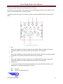
2015 Aries Wings Radio User Manual Copyright © 2015 Aries Wings Consulting Germany -- Version 1.976 04-Apr-15 Aries Wings Radio User Manual Table of Contents Aries Wings Radio Communication............................................................................................................... 6 Installation .................................................................................................................................................... 8 Aries Wings Radio Components .................................................................................................................... 8 AriesRadio.luac...................................................................................................................................... 8 Aircraft Files .......................................................................................................................................... 8 AriesAirborneRadio.dll .......................................................................................................................... 9 AriesAirborneRadio.ini .......................................................................................................................... 9 AriesProtocol.exe .................................................................................................................................. 9 AriesRadio.dll ...................................................................................................................................... 10 Sound Files .......................................................................................................................................... 10 BlackSeaShaddow.map ....................................................................................................................... 10 The radio technology .............................................................................................................................. 10 Voice degradation ............................................................................................................................... 10 Frequency interference caused by two transmitters ......................................................................... 11 Squelch ................................................................................................................................................ 11 Communication Block Out .................................................................................................................. 11 Range limitation .................................................................................................................................. 11 Terrain Masking .................................................................................................................................. 12 Transmission end Click ........................................................................................................................ 12 Airborne Radio ............................................................................................................................................ 12 Airborne Radio Configuration ................................................................................................................. 13 The Radio GUI ............................................................................................................................................. 13 Dial Buttons............................................................................................................................................. 14 Status LEDs .......................................................................................................................................... 14 Carrier LED .......................................................................................................................................... 14 Guard LED............................................................................................................................................ 15 Preset LED .......................................................................................................................................... 15 Manual LED ......................................................................................................................................... 15 2 Aries Wings Radio User Manual Selected LED ........................................................................................................................................ 15 Volume slider ...................................................................................................................................... 15 BOTH ................................................................................................................................................... 15 Moving the GUI ................................................................................................................................... 16 Radio usage ................................................................................................................................................. 16 A10C Radio communication .................................................................................................................... 16 Volume control and receiver/transmitter selection ........................................................................... 17 KY-58 encryption system .................................................................................................................... 18 Locator Beacon ................................................................................................................................... 19 F-86F Radio Communication ................................................................................................................... 20 Aerodromes not preset: ...................................................................................................................... 20 NATO Standard ................................................................................................................................... 21 Radio Box ARC-27................................................................................................................................ 22 FW190D / BF109 Radio ........................................................................................................................... 23 KA50 Radio communication .................................................................................................................... 23 P51 Radio Communication...................................................................................................................... 23 UH-1H Radio Communication ................................................................................................................. 23 MIG21 Radio Communication ................................................................................................................. 24 MI8 Radio Communication ..................................................................................................................... 24 Universal Airborne Radio ........................................................................................................................ 24 Keyboard control of radios ................................................................................................................. 25 Flaming Cliffs Radio ............................................................................................................................. 25 Combined Arms Radio ........................................................................................................................ 25 Changing the air or ground vehicle ............................................................................................................. 25 Controlling the communication quality ...................................................................................................... 26 The quality dialog .................................................................................................................................... 26 Game Master ...................................................................................................................................... 27 Quality sliders...................................................................................................................................... 27 BkGnd Strength Slider ......................................................................................................................... 27 BkGnd Noise ........................................................................................................................................ 27 3 Aries Wings Radio User Manual Terrain mask ....................................................................................................................................... 27 Horizon ................................................................................................................................................ 28 Range .................................................................................................................................................. 28 Voice deg ............................................................................................................................................. 28 Mask Mod ........................................................................................................................................... 28 Set standard values ............................................................................................................................. 28 Send .................................................................................................................................................... 28 TGP air pictures ........................................................................................................................................... 29 Preparing the right MFD for snapshots............................................................................................... 29 TGPwindow ......................................................................................................................................... 30 TGPpos ................................................................................................................................................ 30 Storage ................................................................................................................................................ 30 Creating Air Pictures ............................................................................................................................... 30 Prerequisites ............................................................................................................................................... 33 Computer ................................................................................................................................................ 33 TeamSpeak .............................................................................................................................................. 33 DCS Applications ..................................................................................................................................... 33 Application .................................................................................................................................................. 33 Airborne Radio ........................................................................................................................................ 34 TeamSpeak usage ....................................................................................................................................... 34 Basic Communication Quality ................................................................................................................. 34 TeamSpeak Menu Items ......................................................................................................................... 35 Aries Gossip Box .................................................................................................................................. 35 Aries Eavesdropper ............................................................................................................................. 35 Protocol file ......................................................................................................................................... 36 Export.LUA entry on/off ...................................................................................................................... 36 Radio Communication Quality ............................................................................................................ 37 Additional Information........................................................................................................................ 37 Annex A Copy Rights ............................................................................................................................ 39 Annex B Abbreviations ........................................................................................................................ 40 4 Aries Wings Radio User Manual Figure 1 Aries Wings Environment................................................................................................................ 7 Figure 2 Protocol file ..................................................................................................................................... 9 Figure 3 Airborne Radio .............................................................................................................................. 13 Figure 4 Airborne Radio Panel .................................................................................................................... 14 Figure 5 Intercome service panel ................................................................................................................ 17 Figure 6 KY58 0peration panel .................................................................................................................... 18 Figure 7 F-86F ARC-27 ................................................................................................................................ 22 Figure 8 selecting the quality dialog ........................................................................................................... 26 Figure 9 the quality dialog .......................................................................................................................... 27 Figure 10 MFD layout diagram.................................................................................................................... 29 Figure 11 TGP air picture 1.......................................................................................................................... 31 Figure 12 TGP air picture 2.......................................................................................................................... 32 Figure 13 Aries Radio Menu ........................................................................................................................ 35 Figure 14 Protocol Layout ........................................................................................................................... 36 Figure 15Export Status ................................................................................................................................ 37 Figure 16 External Radio Clients ................................................................................................................. 37 Figure 17 No local Radio ............................................................................................................................. 38 5 Aries Wings Radio User Manual Aries Wings Radio Communication Aries Wings Radio Communication is a system to simulate a complete radio communication environment for simulations over the internet. This encloses airborne radios, ground (ATC/GCI) radios and landline (telephony) connections. The need to develop such a package came from the situation that no independent ground radio was available on the market. Ground radios are necessary for the Aries Wings Radar and cockpit applications like: Aries ASR/PAR ATNAVICS (under development) ATNAVICS is an approach radar application consisting of a search radar and a FPN67 precision approach radar. Aries GCI radar (under development) A PPI used for ground controlled interception. The image below shows a typical environment including Radar, Instructor and Communications. It enables all members of a simulation environment to practice their individual skills in a concerted exercise. 6 Aries Wings Radio User Manual ATC Unit 1 Radar Data Simulation Data Voice Data Tower Computer Center AriesGossipBox ATC Unit 2 GCA Search Radar Server AriesGossipBox AriesGossipBox GCI unit Dedicated Sim Server GCA Final Internet ATC Unit 3 TeamSpeak Server Briefing Tool AriesGossipBox Sim Pilot 1 Aries Airborne Radio Aries Airborne Radio Instructor Pilot Sim Pilot n Aries Airborne Radio Aries Airborne Radio Figure 1 Aries Wings Environment 7 Aries Wings Radio User Manual Installation Aries Wings Radio comes with a small installation program. For details of the installation check the 'Quick Installation Guide'. This manual is applicable for Aries Radio Version 1.976, Apr. 04, 2015. Aries Wings Radio Components The entire package consists of the following files: AriesRadio.luac This file is the interface between DCS world and AriesAirborneRadio.dll it resides in DCS World\AriesWings Aircraft Files Every supported aircraft has a specific LUAC file. For the current version, the following aircraft files are available: A-10C.luac F-86F Sabre.luac FW-190D9.luac Bf-109K-4.luac Ka-50.luac MiG-21Bis.luac P-51D.luac UH-1H.luac Mi-8MT.luac 8 Aries Wings Radio User Manual AriesAirborneRadio.dll The DLL contains all functionality of the airborne radios. It even stays in contact with AriesRadio.dll which is the TeamSpeak radio plugin. The DLL resides in DCS World\AriesWings AriesAirborneRadio.ini The ASCII text file contains all initialization values for AriesAirborneRadio.dll. The file should not be modified manually by the end user. The file resides in DCS World\AriesWings AriesProtocol.exe This program is a centralized protocol generator. It is started automatically as soon as TeamSpeak is started. All running Aries application send their protocol messages to this application. The messages are shown in one common file. In case of problems, this file would be necessary to be send to [email protected]. It can be found at: C:\Program Files\AriesWings\PRCL\ApplicationData\ Aries_Session_Protocol.html The file is in HTML format and can be shown with the help of the internet explorer. Figure 2 Protocol file 9 Aries Wings Radio User Manual AriesRadio.dll The DLL is the TeamSpeak plugin. It contains the entire functionality necessary to realize radio and land line communication on different frequencies and channels. The file resides in C:\Program Files\TeamSpeak 3 Client\plugins Sound Files The sound files contain the background noise for the different type of aircraft. The sound is stored as raw PCM 48 kHz, 16 bit. The files have the ending .snd and may be exchanged with customer files as long as they follow the above described format. jet1.snd A10C jet2.snd all other jets prop1.snd P51 heli1.snd UH1H heli2.snd KA50 BlackSeaShaddow.map This file contains the entire terrain profile of the simulation area. It is used to check the line of sight between two objects. This can be done for radio transmissions as well as radar beam detections. The file resides in C:\Program Files\AriesWings\RadarEnvironment\BlackSea The radio technology The behavior of the radio hardware follows some physical rules which influence the use of the radio. Some of this behavior is even used with Aries Radio. Voice degradation This effect simulates the reduction of audible quality in radio communication. Depending on the radio hardware, the human voice is limited to 8kHz sample rate. All frequencies above 8kHz are cut off. The audible effect for the listener is the absence of sibilants in the voice. All words containing 's' or 'th' are hard to recognize. In aviation radio communication therefore, some words are pronounced in a specific way for better recognition. The number '3' for example, is pronounced as 'tree' instead of 'three'. If voice degradation is switched on, it is hard for beginners to follow the radio communication. Together with background noise on the frequency, it is hard to recognize the content of a message. The amount of voice degradation can be set for each frequency band out of the TeamSpeak plugin menu. There is even a difference in quality between the frequency bands and the used frequency modulation. The best 10 Aries Wings Radio User Manual quality is normally found on UHF AM. This is caused by the dependence of the line of sight. UHF by nature does not recognize reflected energy that much. Therefore frequency interference is small. VHF AM receives a small amount of reflected energy which results in frequency interference. On the other hand, the range is increased a bit. The most interference is observed on VHF FM frequencies. The rule is, as lower the frequency , the higher the interference. Frequency interference caused by two transmitters If two parties are talking at the same time on a frequency, you will hear a terrible noise as audio output. This is caused by the unsynchronized radio wave oscillation of two different transmitters. The carrier frequencies of the two transmitters interfere each other. As a result, the receivers cannot determine the information content of the radio waves. The demodulator filters some random signals. At the loudspeakers, only a terrible hissing can be heard. To avoid such a situation, each party should follow the rules of radio communication, where only one party is allowed to talk at a time. In former times, each transmission was complemented with the term 'over' at the end. This should indicate to other parties, that the frequency is free for the next speaker. This is normally not used any longer. The end of a transmission is determined out of the dialog's context. Squelch Most of the today's radio receiver have a squelch switch. The squelch is a white noise, audible on every frequency band. It is not the leftover from the big bang about 14 Billion years ago, it is caused by the receiver internally mostly caused by the thermal sensitivity of resistors. The big bang noise is actually there, but that weak, that it disappears in the internally caused noise. The squelch switch is used to suppress the white noise. This is done by blocking frequency signals below a certain db level. Voice signals above that level are amplified while white noise below the level is suppressed. In certain situations you will experience signal break offs because of distance or terrain. The voice signal was too weak to pass the squelch level. In this case the white noise suppression can be switched off. The receiver will now amplify all signals which leads in a continuous receiver signal with audible white noise. The advantage could be, that a rest of voice is audible in the white noise without interruptions. The Aries Radio panel shows a continuous green carrier light even if nobody talks on the frequency. Communication Block Out As soon as the PTT button is pressed at a radio box, the corresponding receiver of this frequency is cut off. This is done because of a possible feedback condition which causes a terrible noise on the speakers. The second reason is avoiding to receive your own voice from your own transmitter. So once you press the PTT button, all other parties on this frequency are not hearable anymore. They are blocked as long as you hold the PTT pressed. Range limitation Radio waves in the VHF and UHF frequency band can only be received if transmitter and receiver are in the range of 'line of sight'. If one of the pair is located beyond the horizon, the transmitter is invisible for 11 Aries Wings Radio User Manual the receiver. The distance to the horizon depends of the altitude of the transmitter. It makes a difference being at 100 ft MSL or at 10000 ft MSL with the transmitter. Beside the horizon limit there is even an energy limit. Under best condition (transmitter at 20000 ft MSL) the range would be 220 NM. Terrain Masking If the line of sight between transmitter and receiver is interrupted by a terrain object like mountains, then the received transmitter power is reduced. If the terrain object is that high , that the radio waves cannot pass the obstacle, the reception is suppressed totally. For the function of terrain masking, the file 'shaddow.map' is necessary. It contains the terrain profile of the simulation area. If you do not get contact to a external transmitter, check the distance between your location and the location of the external transmitter and your altitude. Transmission end Click As soon as a transmitter releases the PTT button, the receiver will hear a 'click'. The click is produced in the receiver while the automatic white noise suppression fights again the shrinking energy of the transmission. There is a short uncertainty phase while the receiver raises the amplification where no transmitter energy is present. As a result, the always present white noise will be amplified for a fraction of a second until the receiver notices the zero energy. This is heard as a perfectly clear click. Airborne Radio Airborne radios are used together with the DCS World simulator. In dependence on which type of aircraft is flown, the corresponding radio functionality is activated internally. The Radio consists of a small universal radio panel which resides on top of all desktop windows. It can be switched on or off by a push of a device button. Only the most important radio functions and indications are available. The presentation and functionality is a compromise between available window space and the essential functionality. The current version supports the 3 radios of the A-10C with its generic functions. All other aircraft and helicopter have the radio available but the inputs do not influence the cockpit radio and vice versa. 12 Aries Wings Radio User Manual Figure 3 Airborne Radio Airborne Radio Configuration The Configuration for the Airborne Radio Comes as separate application named 'AriesConfigurator.exe'. For details of the configuration check the 'Quick Installation Guide' In a normal IFR arrival procedure at your home base, you would start with approach control on channel 17. Every transfer of control to the next ATC unit, which requires a frequency change, is done only by a one step turn to the left with the channel selector. This can be achieved without focusing on the frequency indication. So there is less danger of attitude loss in IMC and in turns. The Radio GUI A small window is displayed with three radio panels. The upper panel corresponds to box 1 VHF1, the mid panel to box 2 UHF and the lower panel to box 3 VHF2. The displayed frequencies are the numbers selected on the radio boxes in the cockpit. 13 Aries Wings Radio User Manual Figure 4 Airborne Radio Panel Dial Buttons These buttons may be clicked with the left mouse button to set the frequency of your choice. If one of the models is flown with supported on board radio, the frequency is even set in the cockpit. If a non radio model is flown, the dialed frequency is stored in the initialization file. the frequency is restored with the next mission and a non radio model. In preset mode, a channel index is shown. The index may be modified between 1 and 20 with the dial buttons. Status LEDs At the right side of the Radio Panel, 5 LEDs are displayed to indicate the current status of the radio box. The LEDs marked with 'G','P' and 'M' are clickable to switch between the modes 'Guard', 'Preset' and 'Manual'. However, not all models with their radio boxes support all modes. Therefore modes, which are not available are displayed in grey and are not clickable. Carrier LED As soon as someone talks on the dialed frequency or simply pushes a PTT button, the carrier LED changes to bright green as feedback for the pilot. The carrier remains active for an additional second 14 Aries Wings Radio User Manual after the PTT button is released. This delay function is installed by intention to give the pilot a chance to identify a channel where the message comes from. Guard LED The LED changes to light blue if the Guard function is selected on the cockpit radio box or if the LED was clicked with the left mouse button. The frequency changes to 243.000 if a UHF box was selected , 121.500 if the VHF1 box was selected or to 40.500 if the VHF2 box was selected . Preset LED The LED changes to light blue if the Preset function is selected on the cockpit radio box or if the LED was clicked with the left mouse button. If 'Preset' is on, the frequency indication now shows the selected channel of the radio box. Channelization is mainly used if standard frequencies are needed. In case of flying the A-10C, the frequencies used for the different channels are taken from the cockpit radio boxes. So if you want to change the frequency for a given channel , you have to do it in the cockpit radio box. All other types are equipped with a configurable internal channel list. The Picture below shows radio box 2 set to 'Preset'. So channel 14 becomes active. If you want to see what frequency was configured for channel 14, simply left click into the frequency field and hold the mouse button down. The frequency of channel 14 is shown. Manual LED The LED changes to light blue if the Manual function is selected on the cockpit radio box or if the LED was clicked with the left mouse button. This is the most used function. It shows the manually dialed frequency. Selected LED The LED changes to yellow if the radio box was selected either by a device button or any function which activates the selected radio transmitter. The' selected LEDs' on the other boxes are switched off simultaneously. So only one box can be active for transmissions at a time. If the common PTT device button is used, the radio with the yellow LED will be used for transmissions. Volume slider Each radio may be set to an individual volume level by moving the slider button to the right (increasing volume) or to the left (decreasing volume). The volume levels are stored in the INI file and will be retrieved for the next session. BOTH Some radio cockpit boxes offer the BOTH mode. Once switched to BOTH mode the box is set to listening watch on the official guard frequency. All communication on the dialed frequency and on guard are audible. However, if you want to transmit on guard, you have to switch the box to the guard frequency. As visual feedback you will see the guard LED activated in addition to 'Manual' or 'Preset'. 15 Aries Wings Radio User Manual Moving the GUI The GUI window may be moved to any location on the desktop. The GUI remains always on top of all desktop windows by internal software control. To move the GUI window: Click the GUI's caption and hold the left mouse button down. Drag the window to the location of your choice. The new location is stored in the initialization file and will be restored with the next start of the software. Hint: If FC3 or CA is used in the simulation you will observe, that the mouse cursor is not visible in the view. This makes it more difficult to grab the Radio Panel Window. Therefore it would be a good idea to place the window in one of the screen corners. This position is easy to find if your mouse is blind. To select frequencies manually, it would be necessary to configure frequency keys in the configuration application. Radio usage In case of a clickable cockpit it is observed, whether a radio box is switched on and ready for use. In case of FC3 aircraft or CA vehicles the boxes are ready by default. In any case, take care that the box of your choice is selected. You can see that by the illuminated, yellow select LED on the panel. Then you can use the PTT button or voice activation to open the transmitter. There are some differences between the Radios of different aircraft: A10C Radio communication Three radios are supported. These are: VHF AM Box 1 the most forward radio on the left cockpit console UHF AM Box 2 the mid radio on the left cockpit console VHF FM Box 3 the most backward radio on the left cockpit console The three radios are scanned internally. Every change in the frequency setting is detected and forwarded to the TeamSpeak plugin. Vice versa, if the frequency was changed with the dial buttons in the Aries Radio GUI, the resulting frequency is set in the corresponding A10C Radio box. In the setup application window, it can be defined, which USB device button will be used as PTT and Box select. 16 Aries Wings Radio User Manual Volume control and receiver/transmitter selection The volume can be controlled in the cockpit with the corresponding turn button on the radio box. The slider on the Aries Radio panel is moved in parallel. In addition, volume and receiver / transmitter selection can be controlled from the intercom service panel. Figure 5 Intercome service panel 1. FM Button down disables the receiver speaker for the VHF FM radio box. Button in up position enables the speakers. The volume control with this button is not connected. 2. UHF Button down disables the receiver speaker for the UHF radio box. Button in up position enables the speakers. The volume control with this button is not connected. 3. VHF Button down disables the receiver speaker for the VHF AM radio box. Button in up position enables the speakers. The volume control with this button is not connected. 4. Radio Select The rotary switch selects the radio box which will be active with MIC Button forward. In the configurator it is the button selected for 'PTT Box 1'. INT FM intercom VHF FM transmitter selected 17 Aries Wings Radio User Manual VHF VHF AM transmitter selected HF UHF transmitter selected Empty no transmitter selected 5. VOL The turn button controls all speakers of all sound sources commonly. KY-58 encryption system The KY-58 encryption system is used to scramble digital radio voice packages on UHF or VHF FM so as to make it impossible to understand the content for listener, not possessing the correct decryption key. The system is supported by Aries Radio. Figure 6 KY58 0peration panel 1. ZEROIZE The switch under the cover erases all keys from the memory. Once the keys are erased, encryption is not longer possible. The switch has no function in the current version. 2. DELAY The delay switch has no function in the current version. 3. CRAD The C/RAD selection switch has 3 positions: C/RAD 1 enables voice encryption on the UHF radio box. All transmissions via UHF will be encrypted with the current selected secure key from the FILL rotary switch. PLAIN disables all encryption. If set, all transmissions on every box are readily comprehensible. C/RAD 2 enables voice encryption on the VHF FM radio box. All transmissions via VHF FM will be encrypted with the current selected secure key from the FILL rotary switch. 4. MODE The MODE switch has to be set to OP for normal operations. LD and RV have no function in the current version. 18 Aries Wings Radio User Manual 5. POWER This switch energizes the encryption hardware. It has to be set to ON for normal operations. 6. FILL The rotary switch selects one of six encryption keys . For communication, the transmitter and the receiver have to select the same encryption key. Usage Set the CRAD switch (3) to PLAIN Set the MODE switch (4) to OP Set the POWER switch (5) to ON You will hear a continuous beep as feedback to indicate 'KY58 switched on'. Press the PTT once to stop the beep. Contact the intended station on plain UHF or VHF and coordinate the frequency band and the encryption key (1 - 6) o be used. Set the coordinated encryption key with the FILL rotary switch. Set the CRAD switch to C/RAD 1, if UHF was coordinated or to C/RAD2 if VHF FM shall be used.If you use now your transmitter by pressing PTT, you will hear a short beep indication, that you are on a secured channel. You should start talking after the beep. Receptions on a secured channel are even preceded by a distorted beep. Non encrypted transmissions are clearly audible, even if you are in a secured mode on C/RAD 1 or C/RAD 2. Encrypted voice messages are audible as distorted white noise for normal listener. Locator Beacon In addition to the normal Radio Boxes, military aircraft are often equipped with a locator beacon. This additional transmitter is activated as soon as the ejector seat is used for bailout. The locator beacon transmits a wail on 243.0 MHz until the aircraft is dashed on ground. To use this feature, all A10 pilots should set the UHF radio box to 'BOTH' as a standard. This configuration enables listening watch on 243.0 MHz, while the normal work frequency remains active. Therefore, as soon as a pilot ejects from a cockpit, everybody who listens to 243.0 MHz will notice the bailout wail. If a bailout is initiated on ground, the wail will not be stopped until the bailout pilot leaves the game or selects a new aircraft. However, it is possible to stop the locator beacon (not possible in the real world). If the PTT for Box 1 is pressed, the wail on 243.0 MHz is stopped. Once the aircraft is dashed on ground, the radio panel changes to the CA radio representation. The pilot can contact the rescue crew on all three frequency bands. Since DCS delivers no position information for 19 Aries Wings Radio User Manual the pilot or any CA vehicle, the signal degradation cannot be calculated. Therefore there is no limitation in radio range or receiver quality. F-86F Radio Communication The ARC 27 is a very simple radio from the early days of modern radio communication. It has 19 selectable radio channels with preset frequencies, which cannot be altered during flight. State of the art radios can switch frequencies without any delay. Means, as soon as the pilot sets a frequency, the radio is ready. This is not the case with the ARC-27. The real radio has a build in servo, used to set the channel mechanically. The channel select uses a little time. Therefore it is a good idea to wait 2 seconds after the channel is set before you start talking. As a audio feedback, you will hear a 400 Hz tone as long as the channel is not ready. Another limitation is the frequency resolution. The radio accepts only one decimal digit. Example: 257.8 is usable while 257.875 cannot be set. Nevertheless, in reality, the receiver would probably understand 257.875 on frequency 257.9. The latter is the closest to 257.875. But this is not simulated. Preset channels are not that comfortable if you navigate between different aerodromes. Therefore the preset frequencies should be selected in a way that they cover all aerodromes of the simulation area. If you use the default presets from the mission editor, you have the following frequencies available: 0 1 2 3 4 5 6 7 8 9 10 11 12 13 14 15 16 17 18 243.0 MHz 225.0 MHz 258.0 MHz 260.0 MHz 270.0 MHz 255.0 MHz 259.0 MHz 262.0 MHz 257.0 MHz 253.0 MHz 263.0 MHz 267.0 MHz 254.0 MHz 264.0 MHz 266.0 MHz 265.0 MHz 252.0 MHz 268.0 MHz 269.0 MHz UHF Guard ??? Sukhumi - Babushara Batumi Beslan Gelendzhik Gudauta Kobuleti Krasnodar - Pashkovsky Krymsk Kutaisi - Kopitnari Tbilisi - Lochini Maykop - Khanskaya Mineralnye Vody Mozdok Nalchik Novorossiysk Tbilisi - Soganlug Vaziani Aerodromes not preset: Anapa - Vityazevo Krasnodar - Center 250.0 MHz 251.0 MHz 20 Aries Wings Radio User Manual Krasnodar - Pashkovsky Sochi - Adler Batumi Senaki-Kolkhi 257.0 256.0 260.0 261.0 MHz MHz MHz MHz NATO Standard In reality, there was the Problem, that not all possible aerodromes could be covered with only 18 channels. Therefore, a preset standard was developed, which reserved some channels for common use with one and the same frequency for everybody. 1 2 3 4 5 6 7 8 9 10 11 12 13 14 15 16 17 18 19 20 317.5 MHz 257.8 MHz 385.4MHz 344.0 MHz 362.3 MHz 353.8 MHz 264.2 MHz 282.8 MHz 279.4 MHz NATO combined Radar Fix NATO combined Tower NATO combined GCA Final NATO combined GCA Search NATO combined approach ??? ??? Search and Rescue Combat Scene of Action Variable use Variable use Variable use Home Base Homer (DF) Home Base Tower Home Base GCA Final Home Base GCA Search Local Approach Local GCI (classified) ??? UHF Guard A dangerous problem for a pilot is a frequency change in IMC. He has to look downwards to the console to dial the right frequency. This could lead into a vertigo or an unintended attitude change. The channels are ordered in a way, that the pilot needs only one step on a rotary button to switch to the next station during an instrument approach. So once he has set the start channel, he can switch to the next channel without looking to the radio box. Example: The instrument approach starts with Channel 17, local approach one notch down Channel 16, local GCA Search 21 Aries Wings Radio User Manual one notch down Channel 15, local GCA Final one notch down Channel 14, local Tower. The question now is, how did the pilots contact aerodromes with frequencies not preset in the F86? This is done via the NATO combined frequencies. To contact any Tower, preset channel 2 was used (preset with 257.8). It was ensured, that all military towers kept listening watch on 257.8. The only problem was, if two or more aerodromes were located close together, 257.8 became very busy and all participants had to use maximum communication discipline to avoid call sign and station mix up. Radio Box ARC-27 The minimum configuration for the ARC-27 is 'aircraft battery on' and the left rotary switch is on 'T/R' or 'T/R+G REC'. Figure 7 F-86F ARC-27 1. Left Rotary switch OFF The radio is powered off. The Aries Radio Panel shows no channel number. T/R Transmit and Receive on the selected channel preset frequency. T/R+G REC Transmit and Receive on the selected channel preset frequency. In addition, the radio is on listening watch for the UHF Guard frequency 243.0 MHz. This mode makes the aircraft available on 243.0 MHz all the time whatever channel is selected. ADF Not engaged, acts like OFF. 2. CHANNEL Selects one of 19 different channels for transmit and receive. As a standard, channel 0 is used for 243.0 MHz as Guard frequency. 3. VOLUME Not evaluated for Aries Radio. 22 Aries Wings Radio User Manual FW190D / BF109 Radio The FW190D / BF109 radio communication consists of only one radio with 4 preset channels. Frequenzwahlschalter Since channel one is used for homing functions, only channel 2 (II), 3 (triangle)and 4 (square)should be used for communication. The frequencies can be preset in the mission editor. Kontrollieren Since radio technology was not on the today level , the frequency setting was not that precise. The pilot had an additional turn button to tune the channel frequency in a 30kHz range. By default, it is not necessary to tune the frequencies. Aries radio sets the frequency so as to have the best reception. But it can be played with the tuning button. You will hear the voice fading away and white noise becomes dominant. VOLUME Not evaluated for Aries Radio. Ft / Abst. This selector switches between normal radio communication (Ft) and homing (Abst.). The function is not evaluated foe Aries Radio. KA50 Radio communication The KA50 has two radio boxes available This is: VHF AM Box 1 on the left cockpit console, manual frequency dialing VHF FM Box 2 the right cockpit console, 10 preset channels only The box 1 radio is scanned internally. Every change in the frequency setting is detected and forwarded to the TeamSpeak plugin. The box 2 channel preset cannot be read out. Therefore the 10 preset frequencies must be defined in the configuration program. P51 Radio Communication The P51 has only one radio with 4 preset frequencies. The preset frequencies may be defined in the mission editor. UH-1H Radio Communication The Huey has 3 radios available. There are two VHF radio boxes and one UHF radio box. Only the UHF radio can be switched to 'preset' and 'guard'. Since the UHF radio type is not the leading edge of 23 Aries Wings Radio User Manual technology, the preset channel frequencies cannot be programmed by the pilot. This is done by a mechanic before the pilot enters the copter. It is even not possible to define the preset frequencies in the mission editor. The only possibility is to define the frequencies in the Aries Radio configuration program. MIG21 Radio Communication The MIG21 has only one radio box available. There is no possibility to set frequencies manually. There are 20 preset channels available, starting at channel 0 up to channel 19. The channel frequencies have to be defined with the mission editor. For the proper operation, a certain voltage level of the power supply must be available. During the startup procedure, the battery power can be sufficient to energize the radio. But if the engines are spooled up, the generator takes over. The effect is, that the voltage is below the required level and the radio is switched off until a certain RPM is reached. Then it powers up again. The power up of the radio can be noticed by a rising white noise which stops, when the radio is ready for use. MI8 Radio Communication The Mi 8 is equipped with two radios. The R-863 is for use from the left pilot seat and the R-828 from the right pilot set. Both radios can be selected for transmission via the radio source controller on the overhead panel. R-863 This radio can be used in manual frequency mode and in preset mode. The preset mode covers 20 channels and can be controlled with the red cross rotary switch on the overhead panel. Manual dialing is done from the panel on the center console. To switch between preset and manual frequency mode, use the switch above the manual dialing panel on the center console. R-828 The service panel is located right of the right pilot seat (not visible if the left pilot position is active). The radio supports preset mode only. The red cross rotary switch can select 10 channels. Universal Airborne Radio If FC3 or Combined Arms is used in the simulation or any cockpit without a usable radio, there is normally no possibility to take part in a multiplayer radio communication on different frequencies. The universal Airborne Radio is the Aries Radio GUI window which is created from the AriesRadio.DLL. It is shown on top of the simulator window and enables the FC3 Pilot to dial UHF and VHF frequencies of his choice. 24 Aries Wings Radio User Manual Keyboard control of radios If configured, the radio boxes may be controlled by keyboard. The reason behind is, that DCS World hides the mouse cursor as soon as the simulation changes to FC3 or CA. If the keyboard control shall be used even for A-10C, KA50 and P51, it must be enabled with the Configurator. Flaming Cliffs Radio If the software recognizes the Flaming Cliffs mode, it shows all 3 radios available. The radios are usable as usual. Combined Arms Radio All three radios are even available in Combined Arms mode. However, DCS World does not offer any interface to recognize the Combined Arms Mode. So if you change the vehicle during a session, the last seen radio configuration will remain active. Changing the air or ground vehicle In multiplayer mode it is possible to change the player model during the session. This works with Aries Radio without problems. As soon as the model was changed, the representation and functionality of the airborne radio is adjusted. However, if you change from an aircraft to a Combined Arms Vehicle. The radio remains in the mode of the last aircraft used. The reason is found in a missing signal from DCS World to indicate the change. The software believes sitting still in an aircraft. 25 Aries Wings Radio User Manual Controlling the communication quality Aries Wings Radio tries to come as close as possible to the real world radio communication. This requires the simulation of several physical effects. However, these effects degrade the communication quality, that it could be hard to follow a communication as listener. Therefore, a control dialog exists in TeamSpeak , in which the physical effects can be influenced or be switched off completely. When flying in a community, there should be a common condition of the comunication quality of all participants. Therefore, any change of the conditions are sent to all players. It is not possible to have individual settings for a single player. The quality dialog As long as no radio is active, the dialog is not available. It shall prevent uninvited visitors of the TeamSpeak Server from changing the configuration. Figure 8 selecting the quality dialog After a mission is started, the dialog is available: 26 Aries Wings Radio User Manual Figure 9 the quality dialog Game Master At the begin of a mission, the Game Master button is available for all participants. Only one player can have the control by pushing this button. Means, once the button is pushed by a player, the button changes to gray for all other players and nobody else but the Game Master can change the different control items in the dialog. In the edit field to the right of the button, the username of the current Game Master should appear. During a session, the control should stay with one player to avoid multiple trials to change the configuration. This can be ensured if the controlling player leaves the Game Master button pushed. The control item stay in gray as long as you are not the Game Master! Quality sliders These sliders influence the sample frequency of the microphone. As explained earlier, in radio communication all frequencies above 8 kHz are cut off. The sliders set upper limit of the sample rate. The values range between 2 kHz (the worst quality) and 9 khz as small impact to the quality. If a slider is moved to the most right (value 10 appears) , the degradation is switched off for this frequency band. There is even a difference in quality between the 3 simulated frequency bands. Lower frequencies like VHF FM produce more reflections which extends the range a bit. But it even is impacted by reflections as interference, so that the received voice is a bit degraded. Therefore the standard configuration for the frequency bands is: UHF AM VHF AM VHF FM 8 kHz 7 kHz 6 kHz It is up to the user how these qualities are configured. BkGnd Strength Slider This slider controls the loudness of the background noise globally. The value to the left shows a number between 0 (off) and 100 (maximum noise). The value is published to all player with the send button. BkGnd Noise If this button is pushed, every transmitter produces a vehicle type specific back ground noise on the frequency. Terrain mask This button enables/disables the terrain check (line of sight) between receivers and transmitters. 27 Aries Wings Radio User Manual Horizon This button enables/disables the horizon check (line of sight) between receivers and transmitters. Range This button enables/disables the range check which limits the maximum distance between transmitter and receiver to 200 NM. Voice deg This button enables/disables the voice degradation which is set with the three sliders. Mask Mod A fighter aircraft pilot normally uses a oxygen mask. This creates a typical voice modification, caused by the small volume of air in the mask. Aries Radio simulates this situation by an additional band path filter. If the communication quality becomes too weak, the button can be unpushed to delete the mask modification. The mask modification is set automatically for the following types: A-10C F86 MIG21 Set standard values With a push on this button, all control items are set to the standard configuration which is: all buttons enabled UHF AM slider 8 kHz VHF AM slider 7 kHz VHF FM slider 6 kHz Send After a one or more control items are changed, it has to be sent to the other players. The configuration becomes effective only if the 'Send' button is pushed once after the changes are made. 28 Aries Wings Radio User Manual TGP air pictures One additional feature is to take snapshots from a MFD. The function is available only if you take advantage of evacuated (exported) MFDs , for example on additional monitors. Only evacuated MFDs have fixed desktop coordinates, necessary to find a MFD on the desktop. Preparing the right MFD for snapshots First you need the desktop coordinates of your evacuated MFD. The coordinates can be found in your monitor configuration lua. Look for the entry RIGHT_MFCD. Assuming, that 2 monitors of 1920 x 1080 each are in use. The layout diagram would look like this: 2 x Monitor 1920 x 1080 screen.width 3840 1920 + 80 = 2000 Cockpit View 400 Dislocated right MFD 420 x 420 Figure 10 MFD layout diagram The entry in the monitor configuration LUA would be this: RIGHT_MFCD = { x = 2000; y = 400; width = 420; height = 420; } You need to have the following entries in \DCS World\AriesWings\ AriesAirborneRadio.ini in section [window], key ' TGPpos': [window] TGPwindow=2400 600 0 0 29 Aries Wings Radio User Manual TGPpos=2000 400 420 420 Storage=.\AriesWings TGPwindow The first two numbers represent the desktop X and Y value at which the snapshot window would pop up. The two zeros are place holder only, but must be present. TGPpos These are the most important numbers, defining the desktop position and dimension of the evacuated MFD. The values are the same as defined in the monitor configuration LUA. Storage Defines the path, where the air picture are stored as BMP files. Every existing folder may be entered here. Creating Air Pictures Since the snapshots are not bound to the TGP, you may take snapshots every time from whatever is shown on the MFD for the moment. If you want take air picture for air reconnaissance purposes, go through the following steps: align the TGP so as to have a view usable for air reconnaissance. This means, that the air picture evaluator can identify the details like vehicles, troops and weapons or infrastructure. Push the configured shutter release button. The snapshot window pops up and shows the TGP content. 30 Aries Wings Radio User Manual Figure 11 TGP air picture 1 if one of the targets is of special interest, you may mark it by a yellow frame. Simply position the mouse cursor directly on the target and open a frame by dragging the cursor (left mouse button held down) away from the target. 31 Aries Wings Radio User Manual Figure 12 TGP air picture 2 Close the window by pushing the little cross icon in the upper right corner. The picture will be stored in the configured folder. The file name of an air picture follows a specific convention. Each snapshot is marked by a consecutive index and a time stamp. The first snapshot for pilot BOSSHOG would be: TGP_BOSSHOG_1_1368178124.bmp the second TGP_BOSSHOG_2_1368178140.bmp and so on. BOSSHOG is the call sign read out of the simulation. The next number is the consecutive index followed by the time stamp. This ensures, that the pictures are not overwritten in the next session. 32 Aries Wings Radio User Manual Prerequisites To use one of the radio communication application the following prerequisites must be ensured: Computer Operating System Windows 7, 64 bit. Windows XP may be sufficient, but was not tested. Direct X 9.0 installed (comes normally with DCS World) TeamSpeak TeamSpeak Version 3.0.14 or newer installed on the same computer. TeamSpeak must run with administrator rights! If the AriesRadio.dll is not loaded properly by TeamSpeak (It appears in red in the plugin dialog) then install the VC2010 redistributables from the Microsoft's download center. In the TeamSpeak's options dialog select 'Capture' and set the 'Push to talk' Radio button. In the TeamSpeak's options dialog select 'Hotkeys'. Make sure, that 'Direct Input' is selected in the lower right corner combo box. DCS Applications For Aries Airborne Radio, DCS World installed on the same Computer. Aries Gossip Box may run independently . Application To use the airborne radio or the ground radio, a specific setup sequence has to be maintained for a proper operation. For all cases : Step 1 Start the TeamSpeak client with administrator rights. Step 2 Make sure, that the Aries Radio plugin is activated in the TeamSpeak client and all other coexisting radio plugins are deactivated. This step has to be done only once. Step 3 Connect to the TeamSpeak Server of your choice. Step 4 Change to the commonly used TeamSpeak channel. 33 Aries Wings Radio User Manual Airborne Radio Provided, that the Aries Airborne Radio was installed in DCS World: Step 1 Start DCS World. Step 2 Select any mission from DCS World. Step 3 Start and fly the mission. In the TeamSpeak right information window you should see: Aries Radio info: "Your client name" as A10C 141.450 342.950 030.000 The type of aircraft and the shown frequencies depend on your selected mission. TeamSpeak usage TeamSpeak (TS) should be started before DCS is started. Some important data must be ready in TS when DCS comes up. However, if TS crashes during a DCS session, it can be restarted while DCS remains running. This avoids the situation, that a player has to restart the game in case of a TS crash. Basic Communication Quality TS uses specific CODECs to sample the voice from a microphone at different quality levels. The rule is, as higher the CODEC quality the more data must be transferred over the internet. If the current TS channel is right clicked, the current voice data configuration for the channel is displayed. Real radio telephony is limited to 8 KHz sample frequency. Therefore it would make no sense the set a CODEC for high quality music transfer. It is recommended to use the CODEC named Speex UltraWideband with quality level 7. Aries Radio was developed and tested with this configuration. All higher quality make almost no difference because Aries Radio calculates its own band path filters. Nevertheless it can be tested by the user, which CODEC comes close to his imagination. CODECS may be changed and tested during runtime. Once a CODEC is changed, all other TS clients in the same channel are changed automatically. Another rule is, that the first client in a channel determines the common CODEC setting for all succeeding clients in the channel. 34 Aries Wings Radio User Manual TeamSpeak Menu Items As soon as Aries Radio is installed, you will see an additional Menu Item in TeamSpeak named 'Plugins'. One of the Plugin Items is Aries Radio with a submenu containing the following menu items: Figure 13 Aries Radio Menu Aries Gossip Box This Item starts the Aries Gossip Box application. The menu item is available only if a connection to a TeamSpeak Server was established. Otherwise it is displayed deactivated (grayed out). Aries Eavesdropper This function is very helpful in case of a communication failure. It often happens that a player cannot enter a DCS game server or does not find the right frequency to contact the other players. The Eavesdropper overrides the frequency logic. It enables the user to speak to all players even if he is part of the game or not. If the Eavesdropper is selected, a small Window opens with a PTT button labeled 'ALL': If you want to talk, take the 'ALL' button as PTT button. You will notice, that you talk on all frequencies. Vice versa, you will hear all conversation on each frequency. 35 Aries Wings Radio User Manual Protocol file This menu item gives you direct access to the protocol file of the radio application. This was made to avoid boring directory search if someone wants to inspect the protocol file. A typical layout of a protocol file can be seen in the following image: Figure 14 Protocol Layout The important entries for the user are the location of the protocol file and the E-Mail link. If you want to send the protocol file to the Aries Support division, a direct E-Mail link is prepared. Unfortunately the automated forwarding of attachments is blocked by the operating system. Therefore you need to click the 'log file directory' and drag the protocol file onto the e-mail form. Export.LUA entry on/off For a proper function of the airborne radio, an additional line was entered in the EXPORT.LUA. This line can be activated or deactivated. If activated, you can use the airborne radio together with TeamSpeak as described. If deactivated, all Aries Radio functionality is cut off. This entry was made for the case if you experience unpredictable behavior of DCS World. If you suspect, that Aries Radio is could be the reason, you can simply deactivate all Aries Radio functions and test DCS World without the Aries Products. You should know, that activation or deactivation becomes active not before the next start of DCS world. You can see the status of the EXPORT.LUA entry in the right window of TeamSpeak. The second line of Aries Radio Info shows DCS Export on or off: 36 Aries Wings Radio User Manual Figure 15Export Status Radio Communication Quality See the chapter Controlling the communication quality. Additional Information If other clients have started an airborne radio or a GossipBox, you will see the enabled frequencies of the client if you select the name in the TeamSpeak tree window. This information is available only if you self started an radio application. With the GossipBox, the shown frequencies are at least set to 'LW'. That means, you may call the client on this frequency because he listens on it. For airborne radios, at least a frequency must be tuned in on a radio box. Then it will be published to other radio clients. Figure 16 External Radio Clients If no radio application was started locally you will see only: 37 Aries Wings Radio User Manual Figure 17 No local Radio 38 Aries Wings Radio User Manual Annex A Copy Rights Aries Wings Radio is a product of Aries Wings Consulting, Germany, Copyright © 2015 TeamSpeak3 is a product of TeamSpeak System GmbH, Copyright © 2013 DCS World is a product of Eagle Dynamics VC2010 is a product of the Microsoft Corporation DirectX is a product of the Microsoft Corporation 39 Aries Wings Radio User Manual Annex B Abbreviations A ACC Area Control Center ACT Activated for transmission (Button on the GossipBox's GUI) AIS Aeronautical Information Service AM Amplitude Modulation APP Approach Control Center ASCII American Standard Code of Information Interchange ATC Air Traffic Control D DCS Digital Combat Simulator DLL Dynamic Link Library E ED Eagle Dynamics F FC3 Flaming Cliffs 3 (Eagle Dynamics) FM Frequency Modulation G GCA Ground Controlled Approach 40 Aries Wings Radio User Manual GCI Ground Controlled Interception GUI Graphical User Interface H HID Human Interface Device I INI File name extension for an initialization file L LED Light Emitting Diode LW Activated for Listening Watch (Button on the GossipBox's GUI) P PAR Precision Approach Radar PPI Plan Position Indicator (Radar) PTT Push To Talk T TGP Targeting Pod U UHF Ultra High Frequency 41 Aries Wings Radio User Manual V VAD Voice Activation Detection VC2010 Visual C++ 2010 (Microsoft) VHF Very High Frequency 42