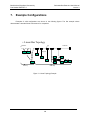
1
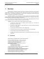
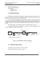
DNETEXT-C CAN Bus Extender, Version 3 User’s Manual Brad Harrison Brad Harrison/Woodhead Connectivity Part Number DNETEXT-C DeviceNet Bus Extender User’s Manual Version 3 Although every effort has been made to insure the accuracy of this document, all information is subject to change without notice. Woodhead LP takes no liability for any errors in this document or for direct, indirect, incidental or consequential damage resulting from the use of this manual. Document Part Number DNETEXT-C-MAN Rev 1.3/3.00 April 2003 Copyright © 2001-2003 Woodhead LP Woodhead LP/Brad Harrison Products 3411 Woodhead Drive Northbrook IL 800 –225-7724 847-272-8133 [email protected] (Email) http://www.connector.com (Web) DeviceNet is a trademark of the Open DeviceNet Vendor Association, Inc. (“ODVA”). All other trademarks are property of their respective companies. TABLE OF CONTENTS 1. OVERVIEW ............................................................................................................................................................................ 2 1.1. 1.2. 1.3. FEATURES.......................................................................................................................................................................2 BASIC OPERATION ........................................................................................................................................................3 REFERENCE DOCUMENTS............................................................................................................................................3 2. USING THIS MANUAL......................................................................................................................................................... 4 3. QUICK START....................................................................................................................................................................... 5 4. GENERAL SPECIFICATIONS ............................................................................................................................................ 6 5. HARDWARE INSTALLATION AND CONFIGURATION............................................................................................ 7 5.1. 5.2. 5.3. 5.4. 5.5. 5.5.1. 5.5.2. 6. OPERATION ........................................................................................................................................................................11 6.1. 6.1.1. 6.1.2. 6.1.3. 6.1.4. 6.1.5. 7. OVERVIEW ......................................................................................................................................................................7 DIP SWITCH SETTINGS ................................................................................................................................................7 LED OPERATION ...........................................................................................................................................................8 POWER REQUIREMENTS...............................................................................................................................................9 NETWORK CABLING AND CONFIGURATION.............................................................................................................9 Cable Lengths.......................................................................................................................................................... 9 Network Termination ...........................................................................................................................................10 A PPLICATION NOTES.................................................................................................................................................12 Extender Theory of Operation ............................................................................................................................13 Network Throughput Design Considerations .................................................................................................13 Fixed Operation ....................................................................................................................................................13 Autobaud Operation.............................................................................................................................................14 Example Configurations................................................................................... Error! Bookmark not defined. TROUBLESHOOTING...................................................................................... ERROR! BOOKMARK NOT DEFINED. Brad Harrison/Woodhead Connectivity Part Number DNETEXT-C 1. DeviceNet Bus Extender User’s Manual Version 3 Overview The Brad Harrison DeviceNet Extenders are a family of products that extend the communications cable lengths for DeviceNet A. By allowing the user to extend the bus length for any given speed, they assist the user in cost-effectively implementing I/O or other nodes on these buses at remote locations that would be more difficult or more expensive to do otherwise. A DeviceNet Extender can be connected in a bus trunk or drop line and is transparent to the other nodes on the bus. It receives and actively re-transmits (store-and-forward) each message from either side of the network without interpreting the message or acting upon it. Each product has two network interfaces with an electrical isolation path between the two. Power is delivered to the unit through the network connectors (5-conductor bus cable). A DNETEXT-C can be used for quite a number of helpful purposes, including • to extend the network beyond its absolute maximum length (e.g., 500 meters for DeviceNet) at the slowest speed • to implement a longer network for a given baud rate (e.g., pushing a 500K baud network beyond 100 m for DeviceNet) • to provide higher speed baud rates for a given network length • to extend the length of the drop cable (e.g., longer drops than 6 m for DeviceNet) • to provide 2600V electrical isolation between the 2 sub-nets • to create a unique network topology instead of a conventional bus structure, such as a star configuration 1.1. Features The Brad Harrison DeviceNet Extender has the following features: • • • • • • • • • • • • Extends CAN-Bus cable lengths - trunk line or drop lines Expands the usable applications for CAN-Bus systems Operates at 125K, 250K and 500K baud Allows operation at higher speeds for specific distances No configurable parameters • Automatic baud rate selection • No address selection required Jumper-selectable terminating resistors on-board the DNETEXT-C Isolates the two sides of the bus - 2500 volts Logically transparent to the Master and Slave devices on the bus Powered from the 24Vdc supplied by bus network or the user 5-pin round mini-style connection for the NEMA mount unit Standard CAN chips manage bus error detection Standard CAN chips handle message bus contention 2 Brad Harrison/Woodhead Connectivity Part Number DNETEXT-C DeviceNet Bus Extender User’s Manual Version 3 • Less than 100 µsec latency • 4 bi-color (red/green) status LED's • CE Compliance •EN 55011 Class A •EN 50082-2: 1994 1.2. Basic Operation There are two bus connections for each extender, referred to as Network A and Network B. The CAN Bus is connected to each side of the extender and each side receives its power and signals from the Bus on its respective side. See Figure 1-1 for a typical application. Whenever a message is transmitted on the Bus to which the extender is connected, it receives the message on the side where it was initiated and performs a store-and-forward of the message to the other side. It then transmits the message to the bus on the other side, following the defined bus arbitration rules. This action is performed for any valid CAN message independent of who generated it or to whom it is intended. There is approximately a 75 µsec propagation delay of the message through the extender. The extender is not addressed as a specific device on the Bus and cannot be interrogated by other nodes. It is transparent to all other nodes on the bus. EXTENDER CAN-Bus T Master Network A PS T A T Network B B PS I/O Nodes I/O Nodes Terminating resistors indicated by “T” Figure 1-1 Typical DNETEXT-C network configuration 1.3. Reference Documents The following documents are referenced in this User’s Manual • ODVA DeviceNet Specification Volume I, Release 2.0 3 T Brad Harrison/Woodhead Connectivity Part Number DNETEXT-C 2. DeviceNet Bus Extender User’s Manual Version 3 Using This Manual This manual serves to help the user to understand the capabilities of the Extender product and how to install and configure an I/O subsystem using these products. Section 3 describes how to quickly connect your extender and get it up and running on the DeviceNet. Section 4 provides the technical specifications for the products. Section 5 describes the installation of the hardware, including mounting, cabling, connection to other I/O subsystem components, and power requirements. Section 0 provides some additional operational information. Section Error! Reference source not found. provides some troubleshooting hints in the event your Extender is not operating as anticipated. 4 Brad Harrison/Woodhead Connectivity Part Number DNETEXT-C 3. DeviceNet Bus Extender User’s Manual Version 3 Quick Start To quickly and easily install your Extender in your DeviceNet system, follow the instructions below. For more details, see Section 5. To Install and Establish Communications 1. Remove the CAN-Bus Extender from the box and connect your CAN-Bus cable to the mini-style connectors (user-supplied) according to wiring specifications for the CAN Bus you are using and described later in this manual. 2. Leave the DIP switches in the FF or all OPEN positions. The DIP switches are set to autobaud both A and B sides from the first valid CAN message on either side. 3. Using on-board jumpers W1 and W2, terminate each side of the CAN-Bus network, as appropriate. (This is especially critical at the higher baud rates.) 4. The DNETEXT-C does not differentiate between A side and B side from a functional perspective. The DNETEXT-C can be oriented with either side toward the Master. 5. Make sure that there is power on both network sides. (The DNETEXT-C isolated power and signal.) 6. Plug the DNETEXT-C into your network. 7. The CAN-Bus Extender will undergo its initialization sequence, flashing the LED’s. After approximately 5 seconds, the Module Status LED (labeled “MS”) will go on solid green and network LED’s (labeled “NSA” and “NSB”) will flash green. 8. Both Network A and B Status LED’s (NSA and NSB) will go on solid once a valid CAN message is received into either side of the Extender and the baudrate auto-detect has been successfully performed. 9. The CAN-Bus Extender is now operating on the network and is ready to repeat messages from either Network A or Network B. 5 Brad Harrison/Woodhead Connectivity Part Number DNETEXT-C 4. DeviceNet Bus Extender User’s Manual Version 3 General Specifications Product: Brad Harrison DeviceNet Bus Extender Description: Electrical extender to extend the permitted cable distances defined for CANbased network products Device Type: Communications Extender Product Revision: 3 DeviceNet Conformance: Designed to conform to the ODVA DeviceNet Specification Version 2.0. Baud rate: 125K, 250K, 500K, 1M - automatic selection Address selection: Bus Connection: Not applicable Extender: Brad Harrison DN10A-MXX, female sockets, female threads Brad Harrison DN01A-MXXX, male contacts, male threads Status Indicators: Module Status: Network A Status: Network B Status: Diagnostic Data: Voltage Isolation: 2500 V Maximum power: Voltage: Current: Mounting: green/red bi-color green/red bi-color green/red bi-color green/red bi-color 11 - 25 Vdc Network A: Network B: Power: 1.8 W LED LED LED LED 140 mA @ 11 Vdc - 60 mA @ 25 Vdc 20 mA @ 11 Vdc - 10 mA @ 25 Vdc DeviceNet Extender: Panel-mount, 4 screws Size: Length: Depth: Height: DNETEXT-C 5.11” (130 mm) 2.27” (57,7 mm) 3.70” (94,0 mm) Operating Temp: 0-70 ºC Humidity: 0-95% RH, non-condensing 6 Brad Harrison/Woodhead Connectivity Part Number DNETEXT-C 5. DeviceNet Bus Extender User’s Manual Version 3 Hardware Installation and Configuration 5.1. Overview A CAN-Bus Extender is a single device connected to two parts of a single CAN-Bus network. NSA DeviceNet Male, Mini W1 2.27” ( 57,7 mm) DGN MS NETWORK A DeviceNet Female, Mini --NET A - --NET B -1 2 3 4 5 6 7 8 SW1 OPEN W2 NSB NETWORK B 5.11” (130 mm) Figure 5-1 DNETEXT-C Bus Extender 5.2. DIP Switch Settings The DNETEXT-C has an 8-pole DIP switch. • • Switch positions 1-4 are used to set the Network A baud rate. Switch positions 5-8 are used to set the Network B baud rate. The baud rates can be set independently, or one side can take its baud rate from the other side (in the “Remote” setting). 7 Brad Harrison/Woodhead Connectivity Part Number DNETEXT-C DeviceNet Bus Extender User’s Manual Version 3 Table 5-1 Baud Rate Settings for Switches Baud rate Side A Side B Position 1 Position 5 Position 2 Position 3 Position 4 Position 6 Position 7 Position 8 Meaning 125K CLOSED CLOSED CLOSED CLOSED Fixed 250K CLOSED CLOSED CLOSED OPEN Fixed 500K CLOSED CLOSED OPEN CLOSED Fixed Autobaud CLOSED CLOSED OPEN OPEN Autobaud OPEN Takes baud rate from opposite side setting. If both sides are remote, Autobaud from either side. Remote OPEN OPEN OPEN N/A Reserved for future use 5.3. LED Operation The DeviceNet Bus Extender has four (4) LED’s that provide visual status information to the user about the product and the DeviceNet network. . See Error! Reference source not found., Error! Reference source not found., Error! Reference source not found. and Error! Reference source not found.. Table 5-2 Module Status LED (labeled MS) LED State Module Status Meaning OFF No Power There is no power through DeviceNet. Device Operational DNETEXT-C is operating normally. Flashing Red Minor Fault Advanced Memory Technology (AMT) buffers space exceeded. Red Unrecoverable Fault DNETEXT-C ay be damaged. Flashing Red/Green Device Self-Testing DNETEXT-C is in self-test mode. Green 8 Brad Harrison/Woodhead Connectivity Part Number DNETEXT-C DeviceNet Bus Extender User’s Manual Version 3 Table 5-3 Network Status LED’s (labeled NSA and NSB) LED State Module Status OFF No Power / Not on-line Flashing Green Idle Fast Flashing Green Autobaud selection Green Meaning On-line DNETEXT-C has no power or device is not operating. DNETEXT-C has not received a valid message for 0.5 sec. The DNETEXT-C is waiting for a valid message to fix the baudrate. DNETEXT-C is operating normally. Flashing Red CAN controller buffer overflow Red Critical link failure (Bus Off) There is more traffic on the network than the system can handle. DNETEXT-C has detected an error that makes it incapable of communicating on the link. Table 5-4 Diagnostic Status LED’s (labeled DGN) LED State Module Status Meaning OFF Normal operation No Power, or Normal Operation with power applied. 5.4. Power Requirements The -Bus Extender subsystem is powered from the 11-25 Vdc provided by the DeviceNet network. The extender consumes 70 mA of current at 24 Vdc, or 1.8 Watts, typical. See Section 4. Power is typically taken from the bus on each side. Each side (A and B) requires power. Power applied to the A Side powers the entire unit except the B Side isolated transceiver. If isolation is not required for your application, then the power line may be jumpered from side A to side B. Care must be taken that the power supply is capable of handling the entire load on both sides of the Extender. 5.5. Network Cabling and Configuration This section provides general guidelines for cabling and configuring a DeviceNet system. You can find detailed specifications in the appropriate ODVA DeviceNet specifications. 5.5.1. Cable Lengths 9 Brad Harrison/Woodhead Connectivity Part Number DNETEXT-C DeviceNet Bus Extender User’s Manual Version 3 The following provide cable length limits for DeviceNet systems. Table 5-5 Network Maximum Lengths - DeviceNet Baud Rate 125 Kbits/s 250 Kbits/s 500 Kbits/s Trunk Line Length Maximum Distance Meters Feet 500 m 1640 ft 250 m 820 ft 100 m 328 ft Drop Length Maximum Cumulative Meters Feet Meters Feet 6m 20 ft 156 m 512 ft. 6m 20 ft 78 m 256 ft. 6m 20 ft 39 m 128 ft. DeviceNet has a limit of 64 nodes per network for any baud rate. The extender does not count as an addressed device. 5.5.2. Network Termination An CAN Bus network must be terminated at each end of the trunk line. The host controller and the last Extender or other DeviceNet device on the network section must always be terminated to eliminate reflections, even if only two nodes are present. Follow the information below when using an extender. Trunk line use For the purpose of network termination, the Extender is treated as the last node on the section of the trunk network to which it is connected. Therefore, when an Extender is used directly in a trunk line, it must be terminated on both the Network A and Network B sides. You must also place a terminating resistor on the other end device of Network A and on the last device on Network B side of the trunk line. Remember that the DNETEXT-C has built-in terminators that can enabled and disabled by attaching or removing jumper plugs W1 and W2. Drop line use When the Extender is used in a drop line (the Network A side is toward the main trunk), the Network A connection is not terminated. In this configuration the Network B section is considered as an independent bus line electrically. The Extender, as the first node in this new bus line and must be terminated, and the last device on the line must also be terminated. Important: Per the DeviceNet specs -- do not terminate devices on drop lines. Note: The DNETEXT-C is configured at the factory with 2 internal terminating resistors on each network – one for Network A and one for Network B – using jumpers W1 and W2. If these are used in a trunk line, no other terminators should be placed at the Extender that end of the network. 10 Brad Harrison/Woodhead Connectivity Part Number DNETEXT-C DeviceNet Bus Extender User’s Manual Version 3 Note: If the Extender is used on a drop line, the internal terminating resistor should be removed on Network A – the drop line directly from the trunk line. Please consult the factory. Figure 5-2 DeviceNet Connectors 11 Brad Harrison/Woodhead Connectivity Part Number DNETEXT-C 6. DeviceNet Bus Extender User’s Manual Version 3 Operation The Extender receives and stores messages received at either network connection and actively retransmits the messages while providing 2500V isolation between the two sections of the network. The two bus connections for each Extender are referred to as Network A and Network B, and they are the same logical network with isolation between them. The Extender may be used to extend the maximum distance that a network can operate at any given speed. • to extend the network beyond its absolute maximum length (e.g., 500 meters for DeviceNet) at the slowest speed • to use a longer network for higher speed baud rates (e.g., pushing a 500K baud network beyond 100 m for DeviceNet) • to provide higher speed baud rates for a given network length • to extend the length of the drop cable (e.g., longer drops than 6 m for DeviceNet) • provide 2500V electrical isolation between the 2 sub-nets The CAN Bus is connected to each side of the Extender and each side receives its power and signals from the Bus on its respective side. Whenever a message is transmitted on the Bus to which Extender is connected, The Extender receives the message on the side where it was initiated and performs a store-and-forward of the message to the other side. This action is performed for any valid CAN message independent of who generated it or to whom it is addressed. The extender is not addressed as a specific device on the Bus and cannot be interrogated by other nodes. It is transparent to all other nodes on the bus. 6.1. Application Notes To help insure ease of installation and reliable operation of your system, the following guidelines should be followed extender installation in your CAN network. 1. You may install the Network A side or B Side of DNETEXT-C toward the Bus Master. 2. The DNETEXT-C takes its logic power from the A Side, but you may power up the Extender from either side first. 3. There is approximately a 75 µsec propagation delay of the message through the DNETEXT-C. 4. In autobaud mode, each side can autobaud from the other side or from the first message on its own side. 5. DNETEXT-C is not a grounded device and the Bus shield is not connected electrically to the device. Therefore, follow appropriate wiring practices to eliminate noise and other problems. 12 Brad Harrison/Woodhead Connectivity Part Number DNETEXT-C DeviceNet Bus Extender User’s Manual Version 3 6.1.1. Extender Theory of Operation As described the extender performs a store-and-forward operation on each message received. The operation is described in this section. The extender will verify and accept (consume) on either network side any and all valid messages. The message will be momentarily stored internally and the extender will immediately attempt to re-send (produce) the message on the other side bus. Because the other side of the extender is a different bus electrically and from a data link perspective, it will perform a negotiation session on that bus section to retransmit (produce) the message onto that section. This action has the effect of doubling the overall number of total attempts to get onto the bus. This is the case because every message is reproduced independent of where the target node exists; that is, the extender does not interrogate the message to determine the target node and does not know physically where the target node is connected. As the bus negotiation is performed on the second side, the re-transmitted message may or may not get on the next bus section immediately. That will depend solely upon the priority of the message the extender is sending with respect to the messages being generated by nodes on that side of the bus and on the amount of overall bus traffic on that side. In the case where the extender does not immediately win the negotiation it stores the messages and attempts to resend it in the same fashion as any other device on the network. To the extent that it cannot produce immediately the message will be stored in an internal buffer until it can be sent. As other messages arrive at the extender they also are put into an internal buffer and re-transmitted as quickly as possible. The internal buffers (one for each side) are FIFO buffers so that the messages for each side will be re-transmitted in the order that they are received with respect to the other messages received on the same side. Up to 15 messages can be held in the internal FIFO buffer for each side. 6.1.2. Network Throughput Design Considerations The effect of the operations described above and the internal propagation delay inside the extender (approximately 75us) as it performs the store-and-forward is that it may be possible to design a network with more traffic that the extender can reasonably be expected to handle. Care should be taken to design the network so that the amount of total traffic does not exceed the capabilities of the total system. Each application and installation has its own requirements and configurations so a definitive formula would be very difficult to define. However, a good rule of thumb would be to set up the scan time for a network that includes a extender that is no faster that twice the fastest scan time possible to achieve the desired communications that may be obtained without the extender. In the event that the network operation prevents all messages on one side from getting out before the buffer on that side fills, subsequent messages will be lost. The extender will continue to process transmitting all stored messages and will accept new messages if once room clears in the buffer. The red LED labeled DGN will illuminate and will remain illuminated for 10 seconds after the “buffer full” condition clears. 6.1.3. Fixed Operation Fixed baud rate operation has several advantages. The first advantage is a fixed baud rate operation which can be used in networks where all devices on one are autobaud only. The second advantage is that 13 Brad Harrison/Woodhead Connectivity Part Number DNETEXT-C DeviceNet Bus Extender User’s Manual Version 3 multiple extenders can be used in series to extend the total length of the trunk or drop line further that with just one extender device. The baud rate is set by setting SW1 switch before powering up the A side of the extender. See Table 5-1. 6.1.4. Autobaud Operation Autobaud operation has the advantage of allowing a system integrator or designer to ignore the operating baud rate when installing the extender. This greatly simplifies DeviceNet commissioning using the extender. Autobaud operation has the advantage of allowing a system implementer or designer to ignore the operating baud rate when installing the DNETEXT-C. The general practice is that when an I/O device is autobaud, it does not transmit a DupMacID request message immediately upon power up. It waits for another (fixed baud rate) device to send its DupMacID message in order use that message to determine to which baud rate the network has been set. Since the DNETEXT-C is not a logical node on DeviceNet, it does not initiate any DeviceNet communications. When both the A and B sides are set to autobaud, a valid message on either side will be used to set the baud rate on both sides. In addition, that message is transmitted out the other side of the network to the nodes there, from which they can establish their baud rates if in autobaud. In the case where no device that initiates this DupMacID sequence, all the autobaud devices will just wait for some valid message to be generated. The DNETEXT-C baud rate is set by setting SW1 switch positions before powering up the A side of the extender, as defined in Table 5-1. 14 Brad Harrison/Woodhead Connectivity Part Number DNETEXT-C 7. DeviceNet Bus Extender User’s Manual Version 3 Example Configurations Examples of valid configurations are shown in the following figures. The first example shown demonstrates a standard linear bus structure for comparison. • Linear Bus Topology Terminator Terminator Tap Tap Terminator Drop Line Nodes Zero Drop Short Drops Figure 7-1 Linear Topology Example 15 Brad Harrison/Woodhead Connectivity Part Number DNETEXT-C DeviceNet Bus Extender User’s Manual Version 3 • Linear Bus Topology - distance doubled Terminator Terminator Extender Extender Tap Tap Terminator Drop Drop Line Line Nodes Zero Drop Short Drops Figure 7-2 Linear Topology with Double Distance Example • Linear Bus Topology - multiple Extenders Terminator Terminator Extender Tap Tap Extender Terminator Drop Line Nodes Zero Drop Short Short Drops Drops Figure 7-3 Linear Topology with Multiple Extenders Example 16 Brad Harrison/Woodhead Connectivity Part Number DNETEXT-C DeviceNet Bus Extender User’s Manual Version 3 • Linear Bus Topology - multiple extended drop lines Terminator Tap Drop Line Terminator Extender Extender Nodes Zero Drop Short Drops Figure 7-4 Linear Topology with Multiple Extended Drop Lines Example • Modified Star Topology - multiple extended drop lines Host PLC Extender Figure 7-5 Star Topology with Multiple Drop Lines Example 17 Brad Harrison/Woodhead Connectivity Part Number DNETEXT-C DeviceNet Bus Extender User’s Manual Version 3 18 Brad Harrison/Woodhead Connectivity Part Number DNETEXT-C 8. DeviceNet Bus Extender User’s Manual Version 3 Troubleshooting This section identifies some of the common problem observed when commissioning or operating a DNETEXT-C Extender. Problem: DeviceNet devices will not communicate on the network Module Status LED is solid Green Network Status LEDs are flashing Green at ½ second intervals Meaning No transmissions have been received by the DNETEXT-C for 0.5 seconds. Possible Solutions: 1. Network cables are broken or disconnected. 2. Network is not properly terminated. 3. All devices have stopped trying to communicate on the network. 4. Power has been lost on the B Side sub-network. Problem: DeviceNet devices will not communicate on the network Module Status LED is solid Green Network Status LEDs are flashing Green quickly Meaning The DNETEXT-C is in autobaud and is waiting for a valid message to fix its baud rate. Possible Solutions: 1. Network cables are broken or disconnected. 2. Network is not properly terminated. 3. All devices have stopped trying to communicate on the network. Problem: Some messages are missed on network. Module Status LED is solid Green NSA and NSB LEDs are flashing Red Meaning Internal CAN buffers are full. Network has more traffic than it can handle. Possible Solutions: 1. Reduce the scan rate from the Master. 2. Reduce the COS frequency on I/O devices. 3. Decrease the assembly sizes of I/O connections. 4. Recalculate the network traffic and bandwidth without the DNETEXT-C. Problem: Some messages are missed on network. Module Status LED is solid Green NSA and NSB LEDs are flashing Red Meaning Internal AMT buffers are full. Network has more traffic than it can handle. Possible Solutions: 1. Reduce the scan rate from the Master. 2. Reduce the COS frequency on I/O devices. 19 Brad Harrison/Woodhead Connectivity Part Number DNETEXT-C 3. 4. DeviceNet Bus Extender User’s Manual Version 3 Decrease the assembly sizes of I/O connections. Recalculate the network traffic and bandwidth without the DNETEXT-C. www.klinkmann.com Helsinki tel. +358 9 540 4940 [email protected] St. Petersburg tel. +7 812 327 3752 [email protected] Moscow tel. +7 495 641 1616 [email protected] Yekaterinburg tel. +7 343 376 5393 [email protected] Mineralnye Vody tel. +7 87922 6 19 34 [email protected] Samara tel. +7 846 342 6655 [email protected] Кiev tel. +38 044 495 3340 [email protected] Riga tel. +371 6738 1617 [email protected] Vilnius tel. +370 5 215 1646 [email protected] Tallinn tel. +372 668 4500 [email protected] Мinsk tel. +375 17 200 0876 [email protected]