1
Altivar 58
Telemecanique
Guide d'exploitation
User's manual
Kit connexion RS485
RS485 connection kit
VW3-A58306
■ Merlin Gerin ■ Modicon ■ Square D ■ Telemecanique
Altivar 58
Kit connexion RS485
RS485 connection kit
Page 2
F
R
A
N
Ç
A
I
S
Page 14
E
N
G
L
I
S
H
1
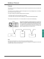
When the speed controller is powered up, the power components and some of the control
components are connected to the line supply. It is extremely dangerous to touch them. The speed
controller cover must be kept closed.
WARNING
After switching the ALTIVAR off, wait for 3 minutes before working on the equipment. This is the
time required for the capacitors to discharge.
E
N
G
L
I
S
H
NOTE
While every precaution has been taken in the preparation of this document, Schneider Electric SA
assumes no liability for any omissions or errors it may contain, nor for any damages resulting from
the application or use of the information herein.
The products and add-ons described in this document may be changed or modified at any time,
either from a technical point of view or in the way they are operated. Their description can in no
way be considered contractual.
14
Contents
Presentation - Installation
16
Connection to Multidrop Bus
17 to 19
Modbus Protocol
20 to 25
E
N
G
L
I
S
H
15
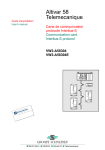
Presentation - Installation
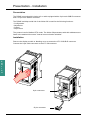
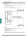
Presentation
The RS485 connection kit includes a 3 m cable equipped with a 9-pin male SUB-D connector
and a 15-pin male SUB-D connector.
The RS485 multidrop serial link of the Altivar 58 is used for the following functions :
• Configuration
• Adjustment
• Control
• Supervision
The protocol used is Modbus RTU mode. The Altivar 58 parameters with their addresses are
listed in the attached document "Internal communication variables".
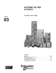
Installation
Remove the display module or blanking cover to access the ATV 58 SUB-D connector.
Connect the 9-pin cable connector to the ATV 58 connector.
E
N
G
L
I
S
H
POWE
R
FAUL z
T
POWE
R
FAUL z
T
9-pin connector
15-pin connector
16
Connection to Multidrop Bus
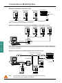
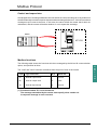
Connection to RS 485 standard bus
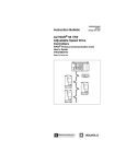
Diagram of cable equipped with connectors
SUB-D 9
SUB-D 15
Recommendations
D(A)
3
7
0V
4
15
D(B)
7
14
• Do not connect anything to pins 1-2-5-6 on the 9-pin
connector.
• Use a shielded cable with 2 pairs of twisted conductors.
• Connect the reference potentials to each other.
• Maximum length of line : 1000 metres
• Maximum length of tap-off : 20 metres
• Do not connect more than 18 stations on one bus.
• Cable routing : keep the bus away from the power
cables (at least 30 cm) with any crossover at right
angles if necessary, and connect the cable shielding
to the ground of each device.
• Fit a line terminator at both ends of the line.
8
9
120Ω
Zt line terminator
recommended at
both ends of the line
D(A)
1 nF
D(B)
Note : the link between pins 8 and 9 of the 9-pin connector has no function on the Altivar 58.
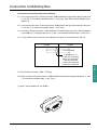
Various accessories are available from the Schneider Automation catalog to aid connection of
equipment.
Cables for the TSX-CSA••• bus are sold in lengths of 100, 200 or 500 m.
TSX-SCA62 subscriber socket
This passive junction box contains a printed circuit equipped with screw terminals and enables
two devices to be connected on the bus (2 x 15-pin female SUB-D connectors). It includes a line
terminator if the subscriber socket is located at the end of the line.
Example of connection
TSX-CSA•••
TSX-SCA62
VW3-A58306
ALTIVAR 58
17
E
N
G
L
I
S
H
Connection to Multidrop Bus
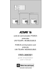
Example of simplified connection on PLC
ALTIVAR 58
ALTIVAR 58
TSX SCM2214
ALTIVAR 58
TSX 47
Channel 1
C3
C3
C3
C4
Note : Physical layer with a capacity of 18 drives.
Example of simplified connection of several ATV58H••••• or ATV58P••••• on PC
ALTIVAR 58
ALTIVAR 58
ALTIVAR 58
ALTIVAR 58
C3
C3
C3
C1
C6
X2
X3
VW3A58104
E
N
G
L
I
S
H
X1
C5
C2
Note : Physical layer with a capacity of 18 drives. Don't forget to configurate the drive adresses in
local mode via the operator's terminal, or programming terminal or PC software respectively
connected to each drive.
Example of connection to a RS485 standard bus with PC and PLC
TSX SCM2214
TSX-SCA62 TSX-SCA62
TSX-CSA•••
TSX-CSA•••
VW3-A58306
VW3-A58306
X1
VW3-A58104
C2
C1
X2 X3
C5
Channel 1
VW3-A58306
ALTIVAR 58
ALTIVAR 58
ALTIVAR 58
Note : • The PC and PLC cannot be connected simustanously to the bus.
• Physical layer with a capacity of 18 drives.
18
TSX 47
Connection to Multidrop Bus
Connection accessories used in the examples
C1 : 9 -pin male connector ("Phoenix Contact" SUBCON 9/M-SH type) with cabling of the pins
3, 4, 6 and 7 (4 conductor shielded cable, 1 mm2 max.), plus male / female adapter 9 -pin
SUB-D (1).
C2 : 9 -pin female connector ("Phoenix Contact" SUBCON 9/F-SH type) with cabling of the pins
3, 4, 6 and 7 (4 conductor shielded cable, 1 mm2 max.).
C3 : Connector "Phoenix Contact " of the SUBCON - PLUS M2 type, plus male / female adapter
9 -pin SUB-D (1). Cabling of the pins 3, 4, and 7 (4 conductor shielded cable, 1 mm2 max.).
C4 : 25 -pin SUB-D male connector with cabling of the pins in correspondence with C3.
C3 pins
C4 pins
3 ----------------------------------- 21
4 -------------------------- not connected
7 ----------------------------------- 23
1 (shielded on 1)
15 and 23 connected
4 and 10 connected
7 and 8 connected
11 and 19 connected
18 and 21 connected
C5 : Box "Phoenix Contact " PSM - PTK type.
C6 : Male connector "Phoenix Contact " SUBCON 9/M-SH type with cabling of the pins 3, 4, and
7 (4 conductor shielded cable, 1 mm2 max.).
(1) male / female adapter 9 -pin SUB-D :
19
E
N
G
L
I
S
H
Modbus Protocol
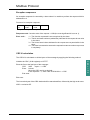
Exchange format :
The Modbus protocol has the following exchange format :
• Speed 19200 bits / second
• Parity : none
• Format : 8 bits + 1 start bit and 1 stop bit
Modbus frames
RTU mode
The frame defined for the Modbus protocol has neither message header bytes nor end of
message bytes. It is defined as follows :
Address
Request
Data
CRC16
The data is transmitted in binary code.
CRC16 : cyclical redundancy check.
The end of the frame is detected on a silence of ≥ 3 characters.
ATV58 address : the ATV58 address varies from 0 to 31 and is configured in menu 4 "CONTROL"
via the PC software or display module.
E
N
G
L
I
S
H
20
Modbus Protocol
Principle
The Modbus protocol is a dialog protocol which creates a hierarchical structure (one master and
several slaves).
The Modbus protocol enables the master to interrogate one or more intelligent slaves. A multidrop
link connects the master and slaves.
Two types of dialog are possible between master and slaves :
– the master talks to a slave and waits for its response
– the master talks to all slaves without waiting for a response (broadcasting principle)
The slaves are numbered from 1 to 31 and number 0 is reserved for broadcasting.
Master
The master manages the exchanges and only it can take the
initiative. The master repeats the question when there is an
incorrect exchange, and declares the interrogated slave absent
if no response is received within a given time envelope. Only
one device can transmit on the line at any time. No slave can
send a message unless it is invited to do so.
E
N
G
L
I
S
H
Slave j
Slave i
Slave k
Note
No lateral communication (i.e. slave to slave) can be performed directly.
The application software of the master must therefore be designed to interrogate one slave and
send back data received to the other slave.
21
Modbus Protocol
Accessible data
The Modbus protocol enables data (bits and words) to be exchanged between a master and
several slaves, and checks these exchanges.
With the ATV 58, only words can be exchanged.
An output object can be read or written. The ATV 58 only contains output objects.
Slave i
Modbus Addressing
Slave j
Transmission
table
Master
User
program
Output
words
Reception
table
E
N
G
L
I
S
H
Slave k
Exchanges
The master, or supervision device, takes the initiative for the exchanges. This master
addresses a slave by supplying it with four types of data :
– the slave address
– the function required of the slave
– the data zone (variable depending on the request)
– the exchange check
The link master waits for the response from the slave before transmitting the next message, thus
avoiding any conflict on the line. Operation in half-duplex mode is therefore authorized.
22
Modbus Protocol
Control and supervision
All management of exchanges between two units which are communicating via an asynchronous
serial link naturally includes exception responses when exchange faults occur. Various inconsistent
messages may be sent to the slave. In this case, the slave will tell the master that it does not
understand, and the master will decide whether or not to repeat the exchange.
Master
ATV 58
Modbus functions
The following table shows the functions which are managed by the Altivar 58 communication
option, and specifies its limits.
The "read" and "write" functions are defined from the point of view of the master.
Code
Type of function
B (1)
Altivar 58
03
Read N output words
06
Write an output word
B
YES
16
Write N output words
B
30 max.
32 max.
(1) Functions marked "B" can be broadcast.
The message transmitted by the master must specify slave number = 0.
A response message is never returned.
23
E
N
G
L
I
S
H
Modbus Protocol
Detailed information on functions
Code 03 :
Read N output words
This function is used to read output words (words which can be written and read
in the slave by the master).
Code 06 :
Write an output word.
This function is used to write a 16 bit output word (words which can only be
written).
Code 16 :
Write N output words
This function is used for the master to read output words in the slave (words which
can be written and read).
Details of frames
Read N output words : function 3
Question
Slave
no.
1 byte
03
No. of 1st word
Hi
Lo
2 bytes
1 byte
Number of words
Hi
Lo
2 bytes
CRC16
2 bytes
Response
Slave
no.
1 byte
03
1 byte
Number of Value of 1st word
------bytes read
Hi
Lo
1 byte
2 bytes
Value of
last word
Hi
Lo
2 bytes
CRC16
2 bytes
Example : read words W450 to W459 of slave 2 (supervision parameters)
E
N
G
L
I
S
H
Question
02
03
01C2
000A
Response
02
03
14
xxxx
CRC16
----------------------
Value
of W250
xxxx
CRC16
Value
of W253
Write an output word : function 6
Question
Slave
no.
1 byte
06
1 byte
Word no.
PF
Pf
2 bytes
Word value
PF
Pf
2 bytes 2 bytes
CRC16
Word no.
PF
Pf
2 bytes
Word value
PF
Pf
2 bytes 2 bytes
CRC16
Response
Slave
no.
1 byte
06
1 byte
Write N output words : function 16 (H'10' )
Question
Slave
no.
1 byte
10
No. of 1st word
Hi
Lo
1 byte
2 bytes
Number
of words
2 bytes
Number Val. of 1st word
CRC16
---of bytes
Hi
Lo
1 byte
2 bytes
2 bytes
Response
Slave
no.
1 byte
10
No. of 1st word
Hi
Lo
1 byte
2 bytes
Number of words
Hi
Lo
2 bytes
CRC16
2 bytes
Example : write values 15 and 400 in words W400 and W401 of slave 2
24
Question
02
10
0190
0002
04
Response
02
10
0190
0002
CRC16
000F
0190
CRC16
Modbus Protocol
Exception responses
An exception response is returned by a slave when it is unable to perform the request which is
addressed to it.
Format of an exception response :
Slave
no.
1 byte
Response
code
1 byte
Error
code
1 byte
CRC16
2 bytes
Response code : function code of the request + H’80 (the most significant bit is set to 1).
Error code :
1 = The function requested is not recognized by the slave.
2 = The bit and word numbers (addresses) indicated in the request do not exist
in the slave.
3 = The bit and word values indicated in the request are not permissible in the
slave.
4 = The slave has started to execute the request but cannot continue to process
it completely.
CRC16 calculation
The CRC16 is calculated on all the bytes of the message by applying the following method.
Initialize the CRC (16-bit register) to H’FFFF.
E
N
G
L
I
S
H
Enter the first to the last byte of the message :
CRC
XOR
<byte> —> CRC
Enter 8 times
Move the CRC one bit to the right
If the output bit = 1, enter CRC XOR H’A001—> CRC
End enter
End enter
The low order bytes of the CRC obtained will be transmitted first, followed by the high order ones.
XOR = exclusive OR.
25
VVDED397057
W9 1493690 01 11 A02
85597
1998-02