1
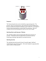
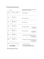
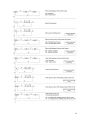
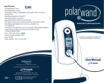
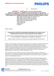
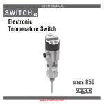
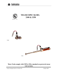
Stauff Pressure Controller
SPWF
User Manual
Version 1.0
Contents
1. Introduction…………………………………………………………........ 3
2. Pressure Switch Description………………………………………… 4
3. Start of Operation……………………………………………………….. 4
4. Switching On and Off…………………………………………………… 5
5. Programming………………………………………………………………. 6
6. Technical Data…………………………………………………………….. 12
7. CE Conformity…………………………………………………………….. 13
8. Maintenance………………………………………………………………. 13
9. Troubleshooting.………………………………………………………… 14
10. Cleaning………………………………………………………………….… 14
11. Disposal……………………………………………………….…………... 14
2
1. Introduction
Thank you for purchasing a Stauff model SPWF programmable pressure
switch. We appreciate your business and look forward to working with you.
These operating instructions have been created for the most general user
of this product. Each and every application can be different, and if you feel
that these instructions do not meet your requirements please feel free to
contact us, and we will be happy to assist you.
Scope
These instructions apply to the SPWF units with two switching outputs, or
one switching output and one analog output in individual sections.
Safety Instructions and Warnings
Please read these instructions before installation and startup. Failure to
follow these instructions will make all warranty claims null and void.
• Only qualified persons are permitted to install the equipment and make
the electrical connection. The correct tools must always be used.
• Please ensure that the pressure switch is suitable for your application.
• Under regular working conditions the surface temperature of the housing
can become 15K warmer than the ambient temperature. High ambient
temperatures can result in surface temperatures which make a protection
against contact necessary.
• Please note that the SPWF unit can be effected by or damaged by strong
magnetic fields.
• The SPWF unit must not be opened, painted (coated) or modified.
• The SPWF unit must not be used if damaged. If damaged during
operation, suitable measures must be taken to prevent persons or
property from being put at risk by the damaged unit.
• The SPWF unit must only be repaired by Stauff
3
2. Pressure Switch Description
The SPWF unit will have one of two output options:
1. Two programmable switching outputs
2. One programmable switching output and one analog output
Both the switching outputs and the analog output are adjusted by use of
the two programming buttons (S1 & S2) on the display face of the SPWF
unit. By use of these two programming buttons the user will also select
units, switching points, reset points (hysteresis / window), switching
functions (normally open / normally closed), and switching from NPN to
PNP.
The password protection that can be activated is a special feature, and will
help in preventing unauthorized persons from modifying and adjusting
parameters.
The rotating capability makes it possible for the electrical output and the
display to be aligned independently.
Correct Purpose of Use
The equipment is only authorized for proper use for its correct purpose.
Failure to do this will invalidate all warranties and will release Stauff
Corporation from all responsibility.
3. Start of Operation
The accepted technical regulations must be complied with during
installation and dismantling. The system component must be
depressurized prior to installation and dismantling. All safety regulations
must be complied with, particularly when working on an electrical system.
All connections to external electrical equipment must be made in
accordance with technical regulations.
4
• The power to the system must always be switched off when the SPWF unit
is being connected.
• The electrical connection is made via the M12 plug attached to the
housing.
• The plug‐in electrical connection must be protected in accordance with
the manufacture’s specifications.
• The load can be connected to ground (switching PNP) or to the supply
voltage (switching NPN)
5
4. Switching On and Off
The SPWF is switched on when the supply voltage is applied. There is not
an on/off switch. A brief initialization phase occurs when the supply
voltage is applied to the switch. The switch is then in normal operating
mode. The operating pressure is shown on the display and the switch
outputs are operational. Briefly pressing S1 causes switch point one to be
displayed. Briefly pressing S2 causes switch point two to be displayed.
5. Programming
During the initialization period the display and switching point status LED’s
will illuminate. The nominal pressure will display for a brief moment.
During this phase the outputs are inactive.
After initialization the switch will resume normal operating mode. The
pressure appears on the display. The outputs are active and the switching
point status LED’s will indicate the status of the switching outputs.
Briefly pressing the S1 or S2 buttons causes the relevant switch point to be
momentarily displayed. The status LED’s flash for as long as the switching
points are being displayed.
Pressing the button for longer (hold button S1 or S2 down until display
flashes) causes the current pressure to be taken over as the switching
point. The hysteresis remains unchanged. If the password has been
activated (see programming mode) the programming is only accepted after
the password has been entered.
The switching outputs can be programmed using the control buttons
without the presence of pressure. The programming sequence must run
without interruptions. If delays of approximately 30 seconds or more
occur, the switch automatically exits programming mode and switches to
normal operating mode. All previous changes are lost.
6
Status LED Switching Output
Password
The Password protection can be activated in programming mode. The
pressure switch is protected from and unauthorized setting modifications.
Be sure to keep the password somewhere it will not be lost. If you forget or
have lost the password please contact Stauff for assistance. The serial
number of the unit will be required in this case. (On the ID label)
Switching Points and Hysteresis / Window
The switching outputs can be programmed without the presence of
pressure. The decimal points are specified in accordance with the
measuring / adjusting range and the associated accuracy.
Switching function
The switching function (normally closed / normally open) is defined
individually for each switching point. Each switch output is programmed to
switch to PNP or NPN potential.
7
The quick programming menu
8
The complete programming menu
9
10
To Exit the Menus
1. Possibility – After the selection, the menu will automatically be
closed whether the modified value is stored or not.
2. Possibility – It is possible to exit the menu anytime by pressing the S1
and S2 simultaneously.
a. User menu 0.1‐3s
b. Set up menu >3s
3. Possibility – If no button is pressed for 30 seconds the menu will be
closed automatically.
Error Message
A. Error ‐ Flashing display of the measured pressure
A. Cause ‐ Measured pressure outside the adjustment range
B. Error ‐ Flashing of the display during the programming
B. Cause ‐ Entered value was not valid (switching point above / below the
adjustment range, reset point above / below the adjustment range, reset
point above the switching point, analog output span is smaller than 20% of
the adjustment range, filter more than 2s) the buttons are locked for 3
seconds and the switch takes over the next possible value
11
12
CE ‐ Conformity
The SPWF programmable electronic pressure switch complies with all
requirements of EN 61 326 with regard to interference emission and
immunity for use in industrial areas. We recommend the use of shielded
cables. Installation and cable routing must be carried out correctly in order
to maintain the effective protection from electromagnetic interference.
8. Maintenance
The SPWF units described in this manual are maintenance free. This unit
will operate in a stable state for long periods, thus regular adjustment is not
required.
Removal of this unit is recommended if any malfunctions occur. This device
is not to be repaired by the customer. It is strongly recommended that the
unit be replaced or returned to Stauff for additional testing.
13
9. Troubleshooting
No modifications are to be made to the device. Only the manufacturer is
allowed to perform repairs.
10. Cleaning
The exterior of the SPWF unit can be cleaned using a soft, moistened cloth.
Heavy soiling can be removed using a mild cleaning agent.
The SPWF unit must not be opened under any circumstances!
Aggressive chemicals and or hard scrubbing can damage the surface, in
particular the display film.
11. Disposal
The packaging and end user parts must be disposed of in accordance with
the regulations of the country in which the device is installed.
14
User Notes
______________________________
______________________________
______________________________
______________________________
______________________________
______________________________
______________________________
______________________________
______________________________
______________________________
______________________________
______________________________
______________________________
______________________________
______________________________
______________________________
______________________________
15
Stauff Corporation
7 Wm Demarest Place
Waldwick, NJ 07463
USA
Stauff Filtration
303 Metty Drive, Suite # 3
Ann Arbor, MI 48103
USA
Note – This manual is subject to alteration without notice
16