Transcript
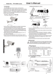
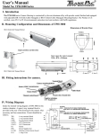
User's Manual
҇. Introduction
҉. Fitting instructions for camera
The Camera Housing is constructed from
die-cast aluminium and is powder coated and stove finished.The design
and manufacture is to the highest technical standard with environmental
protection to level IP 66. The Housing is supplied complete with an
adjustable Semi-Cable-Managed Mounting Bracket.
7
1
2
3
6
8
4
9
5
7
1
2
3
4
5
҈. Mounting configuration
(K)
Heater (12VDC,24/110/230 VAC)
Heat shield
Thermal control board
Camera mounting platform
Terminal block assembly
Fig.3
6
7
8
9
Cable conduits PGB13.5 x 2
Captive retainning 1/4" Screws x 3
Heater wires, Ground wire
Ground wire
(H)
(A)
(C)
(G)
(D)
(E)
(G)
(E)
(F)
(F)
(J)
(D)
(B)
(G)
1. Use the rear section of the Mounting Bracket (D) as a template for marking the position
on the wall of the Mounting Holes (H). Remove & drill to pattern required.
2. Attach the Mounting Bracket arm to the wall using the rawlplugs and screws provided.
3. Attach the main Housing enclosure (K) to the Mounting Bracket with 2 of 1/4" x 14.7 mm
Trilobular screws (F) provided.
4. Release Screw (E) on the Mounting Bracket to pan the Housing and release screw (G)
to tilt the Housing. Position the Housing as required for the correct Camera coverage
then tighten both Screws to secure.
5. Feed cables through the hole of Cover Plate (B) on the Mounting Bracket from the wall
or by using cable conduits as required.
(C)
(I)
1. Unscrew the 3 captive Retaining Screws (C) and remove the Housing Cover (A) from
the Housing Base (B).
2. Release the 4 Keyhole Screws (F) and then slide and withdraw the Camera Platform
(G) from the Housing Base (B).
3. Mount the Camera (H) onto Platform (G) using the 1/4" UNC Screw ( I ) Supplied,
ensuring that the Insulation Pad (J) is mounted between the Platform and the Camera.
Always check that the Camera is firmly attached to the Platform.
4. Connect the Camera / Heater power cable to the rear Terminal Block (E) through the
first Cable Conduit (D) referring to the circuit diagram shown in section IV. for the
terminal designations.
5. Connect the video cable to the Camera through the second Cable Conduit(D).
Fig.1
IMPORTANT NOTE:
ALWAYS UNPLUG THE TOP SECTION OF THE EARTH WIRE FROM THE BASE
WIRE WHEN DISASSEMBLING THE HOUSING. REMEMBER TO PLUG THE TOP
AND BOTTOM TOGETHER AGAIN WHEN REASSEMBLING THE HOUSING.
(B)
Ҋ. Wiring diagram
90±
Fig.4 shows the internal wiring diagram for the window demister.
A spare 6 way terminal block is provided at the rear of the enclosure for the camera
when necessary and lens connections. Circuit identified as follows:
90±
TB.1
TB.2
FTB.1
FS.1
STAT.1
65
6 way terminal block
3 way terminal block
Fused terminal block
3 Amp. Fuse
28к Thermostat
H.1
Heater,
Heater,
Heater,
Heater,
12 VDC
24 VAC
110 VAC
230 VAC
P.C.B.1 Thermal control circuit board
Fig.4 Wiring diagram
(H)
ENCLOSURE BASE
THERMOSTAT TURN OFF AT 28к RISING TEMPERATURE
TURN ON AT 18к DECREASING TEMPERATURE
STAT.1
TB.1
1
2
3
4
5
6
Fig.2
Inner space for camera mount
W90 x H70 x L230mm
SPARE
78
N
H.1
E
1 2 3 TB.2
L
P.C.B.1
CHASSIS EARTH
FTB.1 FS.1
COVER EARTH