1
INSTALLATION GUIDE
AND USER MANUAL
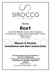
SOPHIA Towel Rail
Bathroom Heater
With integral Seven Day LCD Programmer
By
Intelligent Heating Solutions
1
Please ensure that these instructions and guidelines are fully
understood and adhered to when installing and using this appliance.
TABLE OF CONTENTS
PAGE 3
IMPORTANT GENERAL GUIDELINES
PAGE 4
BATHROOM INSTALLATION GUIDELINES
PAGE 5
WALL MOUNTING GUIDELINES
PAGE 6
ELECTRICAL CONNECTION / OPERATING MODES
PAGE 7
OPERATING MODES CHART / DIAL DIAGRAM
PAGE 8
OPERATING MODES / PROGRAMMING
PAGE 9
DAILY / WEEKLY PROGRAMMING
PAGE 10
PILOT-WIRE PROGRAMMING / ANTI-TAMPER LOCK
PAGE 11
WARRANTY / PURCHASE DETAILS
PAGE 12
INTELLI HEAT COMPANY DETAILS
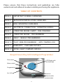
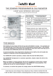
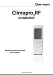
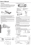
Integral Seven Day LCD Intelligent Programmer
Plus control
LCD Display with
blue back-light
Minus control
Programming
On / Off
Receiver
Manual switch
2
1. Installation and all maintenance must be carried out by a qualified person. This
appliance must not be used/operated by people (including children) whose sensory,
physical or mental capabilities prevents them from doing so safely. Take special
care when children are around and ensure that they do not tamper with the appliance.
2. The manufacturer cannot be held responsible for any fault, damage, or personal
injury caused in the event of these instructions not being fully adhered to, or where
non-original materials or accessories have been used. Such non-observance would
also invalidate the warranty.
3. This heater is filled with a special Thermodynamic Fluid. Any repair involving
opening the access to this fluid must be carried out by an electrician approved by
the manufacturer. The manufacturer must be contacted in the unlikely event of any
leakage of this fluid. Please note that all regulations for the disposal of heating fluid
and electrical appliances must be fully adhered to.
4. If the cable or any other electrical part fails or becomes damaged, repair or
replacement must be carried out by an electrician approved by the manufacturer,
or by a suitably qualified, experienced electrician familiar with such products who
has the necessary instructions.
5. This product must not be positioned below an electrical socket and all applicable
regulations relating to the installation of electrical appliances in bathrooms / splash
areas must be fully adhered to. See page 4 for further information and guidance.
6. WARNING – to avoid the risk of injury to children, this appliance should be installed
so that the lowest heated rail is at least 600mm above the floor.
7. During normal operation it is normal for the bottom pipe and the top one not to heat
up. This is to facilitate the flow and expansion of the thermodynamic fluid.
8. Do not use this appliance near sources of gas, explosives or flammable liquids.
Connection of
the PILOT WIRE to any LIVE (LINE), NEUTRAL or EARTH connection will destroy
the thermostat. If the black pilot wire is not to be connected to an external pilot
wire programmer, it must be insulated/isolated to ensure this does not occur.
3
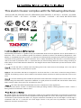
This electric heater complies with the following directives:
2006/95/CEE, 89/336/CEE, 2005/32/CEE and the norms EN 60335-2-43:2003 + A1:2006 + A2:2008;
EN 60335-1:2002 + A11:2004 + A1:2004 + A12:2006 + A2:2006 + A13:2008; EN 62233:2008.
CL
IP44
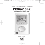
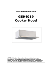
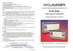
The following information is a guide to help you understand what electrical appliance can be placed where in a
bathroom. This is not an installation guide and reference should be made to the IEE Wiring Regulations (16th
Edition) or a qualified electrician. Firstly, it is important to understand the rating by which electrical appliances are
classified. IP rating stands for "Ingress Protection" and is always followed by two characters. These two numbers
refer to the level of protection and it is important that you choose fittings with the correct rating according to
where they are to be sited within the bathroom. The diagram above shows a bathroom split into three clear zones:
1, 2 and 3 .
is inside the bath or shower itself. Any fitting used in this zone must be low voltage, (max 12v) and be
rated at least IP67 which is total immersion proof.
is the area above the bath to a height of 2.25m from the floor. In this zone a minimum rating of IP44 is
required. If the fitting is 240v a 30ma residual current device (RCD) must also be used to protect the circuit in this
zone.
is an area stretching 0.6m outside the perimeter of the bath and to a height of 2.25 from the floor. In this
zone IP rating of at least IP44 is required. In addition it is good practice to consider the area around a wash basin,
within a 60cm radius of any tap to be considered as zone 2.
(This Zone Has Now been Withdrawn From the 17th Edition of the regulations)
In addition to the above, if there is a likelihood of water jets being used for cleaning purpose in zones 1 and 2 a
fitting rated a minimum IP65 must be used.
EN 60529 outlines an international classification system for the sealing effectiveness of enclosures of electrical
equipment against the intrusion into the equipment of foreign bodies (i.e. tools, dust, fingers) and moisture. This
classification system utilizes the letters "IP" ("Ingress Protection") followed by two or three digits. (A third digit is
sometimes used. An "x" is used for one of the digits if there is only one class of protection; i.e. IPX4 which
addresses moisture resistance only.)
4
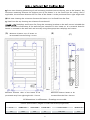
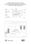
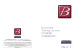
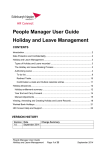
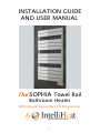
Front view showing positioning of wall mounting brackets (two at the top, one at the bottom), the
minimum mounting distance the highest part of the heater is to be fixed from the ceiling. And if
applicable, the minimum distance the far sides of the heater is to be positioned from right-angle walls.
Side view showing the minimum distance the heater is to be fixed from the floor.
View from the top showing rear distance from the wall.
Rawlplugs and Screws for fixing the mounting brackets to the wall are not included due
to the unknown construction of the wall that you intend to fix this heater to. It is essential that this
heater is mounted to the wall level and securely using the appropriate rawlplugs and screws.
(A)
Minimum distance top of heater to
(B)
(C)
Wall
be mounted from the ceiling: 150 mm
Wall
Floor
Minimum distance sides of the heater to be
Minimum distance heater to be
positioned away from right angle walls: 150 mm
mounted from the floor: 600 mm
All dimensions in millimetres - Drawings not to scale.
Product Specifications (heights includes thermostat/programmer)
500
980
500
45
SOP 500
15.5
750
1430
500
45
SOP 750
22.5
5
This heater is
, therefore
and
(Green / Yellow). The cable for this heater has the following cables: (Grey or Blue = Neutral)
(Brown = Live) (Black = Pilot Wire, which is only for communication to an external hard-wired programmer,
if not,
, it must be properly insulated and isolated).
For the installation in a bathroom or a potential splash area, RCD protection is essential, and positioning,
and all electrical connections, switching and installation must be compliant with all the regulations regarding
installing electrical appliances in bathrooms (see page 4). Only a qualified electrician should install this unit.
The connection must be made in compliance with the
regulations in force; before connecting the electric resistance to the line, check the voltage and power values
indicated on the data plate.
The electric supply circuit of the radiator must be protected by a 30 mA RCD protected circuit. The opening
distance between the contacts must be greater than 3mm. Moreover, the circuit must be easily accessible.
Press ‘ON/OFF’ button (fig.1) to turn the appliance ON or in Stand-by mode.
When On, the bottom area of the display shows the current time, on the top the temperature setting is displayed.
Two different levels of temperature can be set:
COMFORT TEMPERATURE is the temperature setting for ‘Chrono’, ‘Pilot Wire or Fil Pilote’ and ‘Comfort’ modes:
BACKGROUND TEMPERATURE is the temperature setting for the ‘Night’ and ‘Chrono’ mode.
In each mode the required temperature can be set by pressing the [+] and [-] buttons.
IMPORTANT! BACKGROUND Temperature has to be lower or equal to the Comfort Temperature, and the
priority is assigned to the Comfort Temperature. For this reason Night Temperature can only be set in the
range 7° C ÷ Comfort Temperature, whereas the Comfort Temperature can be set within the whole range
7°÷32° C (and in case of a value lower than the Night Temperature, the system will automatically re-set the
new Night Temperature at the same value as Comfort Temperature).
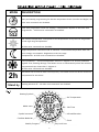
OPERATING MODES
Press the [Prog] button to shuffle between the different operating modes. An icon on the
display indicates the current operating mode (please see the charts below and on page 5).
2h
Chrono/
Time
Pilot Wire
Comfort
Night
6
Anti-Frost
Timer
MODE
DESCRIPTION
Daily and weekly programming for the two temperature levels (Comfort and Night). All
Pilot-wire commands are disabled.
Pilot-wire programmer mode. All settings / temperatures depend on the Pilot-wire
programmer - All Pilot-wire commands are enabled.
The comfort temperature corresponds to the temperature set by the user. Regulation
to the high range temperatures.
All Pilot-wire commands are disabled
Night temperature reduction mode to maintain a comfortable temperature with minimum energy consumption. Regulation to the low range
Temperatures. All Pilot-wire commands are disabled.
Frost protection - minimal temperature fixed at 7 degrees C to ensure protection
against frost/freezing damage. The heater comes on automatically when the ambient
temperature drops lower than 7 degrees C.
All Pilot-wire commands are disabled.
This Mode can be used to heat a room quickly. The heater will be set at the maximum
2h
temperature for two hours.
Stand by
Heating element off - All Pilot-wire commands are disabled.
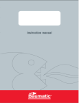
Heating Symbol
Set Temperature
Mode Icons
24h Time
Symbol not used
Infrared Receiver
Comfort Mode Bar
Clock
Key Lock Icon
Weekly Program
7
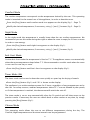
Comfort Mode
The comfort temperature corresponds to the temperature desired by the user. This operating
mode is intended for the normal use of the appliance, in order to heat the room.
Press the [Prog] button until comfort mode icon appears on the display (fig.1 - Page 7).
Modify the desired temperature, if necessary, using [+] and [-] buttons (fig.2 - Page 9).
Night Mode
In the night mode the temperature is usually lower than the set comfort temperature. We
recommend you use this mode during the night or when the room is empty for 2 hours or more
in order to save energy.
Press the [Prog] button until night icon appears on the display (fig.1).
Modify the desired temperature, if necessary, using [+] and [-] buttons (fig.2).
Anti-frost Mode
On the Anti-frost mode the temperature is fixed at 7° C. The appliance comes on automatically
when the room temperature drops below 7° C. We recommend to use this mode when the room
is not used for one day or more.
Press the [Prog] button until Anti-frost icon appears on the display (fig.1).
Timer Mode (2h)
The timer mode can be used to heat the room quickly or speed up the drying of towels.
Press the [Prog] button (fig.1) until ‘2h’ is shown on the display.
The appliance is on at the maximum power for 2 hours, regardless of any temperatures set by
the user for safety reasons, ambient temperatures above 35° C are not allowed by the system,
so if that temperature is reached, the thermostat will switch the unit off.
The timer mode is set to stop automatically after the 2h period and will then revert to the
previous mode. If necessary the user can switch back to other modes at any time, by simply
pressing the [Prog] button (fig.1).
Chrono Mode
This operating mode allows the user to set different temperatures during the day. The
Comfort/Night temperature and the time intervals can be programmed.
8
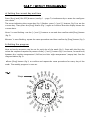
a) Setting the current day and time
Press [Prog] and [ON/OFF] buttons (see fig.1 - page 7) simultaneously to enter the configuration mode.
The arrow indicating the current day (fig.1) flashes: press [+] and [-] buttons (fig.2) to set the
current day. Then press the [Prog] button (Fig.1) again to confirm. Now the display shows the
current time.
‘Hours’ is now flashing: use the [+] and [-] buttons to set and then confirm with [Prog] button
(fig.2).
‘Minutes’ is now flashing: repeat the same procedure and then confirm by [Prog] button (fig.1).
b) Setting the program
Now an hourly sequence can be set for each day of the week (fig.1). Start with the first day,
select the sequence required by means of the [+] and [-] button (fig.1) to choose, for each hour,
between the ‘comfort temperature’ (full bar) and the ‘night temperature’ (empty bar). See the
diagram below (fig.2).
Press [Prog] button (fig.1) to confirm and repeat the same procedure for every day of the
week. The weekly program is now set.
Steps
9
Pilot-wire Mode
This heater can be centrally controlled and programmed as a single unit, or combined with an
electric heating system that includes several other heaters, provided that the other heaters are
equipped with a Pilot wire. Please note that such ‘hard wired’ use of the pilot wire requires
connecting a wire to and from the pilot wire of each heaters to a central hard wired Pilot
Programmer, which usually, as with our ZoneRay Pilot-wire programmer, enables individual
daily temperatures and timings to be set for up to four zones over a seven day period, which
is automatically repeated every seven days (several heaters can be grouped in each zone). This
is not recommended for retro-fit systems as, unless visible trunking of wiring is acceptable,
such wiring will need to be chased into the walls.
Alternatively, if such centralized programming is preferred, our wireless version of ZoneRay is
the solution. This system simply requires connecting the pilot wire from each heater to a small,
discrete wall-mounted receiver (one receiver per heater). Programming and control commands
can then be achieved as per the Pilot-wire system using our wireless version of the ZoneRay
central programmer. Additionally, as opposed to the hard wired version, the wireless ZoneRay
version enables the individual management of up to six zones.
Any Pilot-wire Programmer used must give commands corresponding to the GIFAM standard
(Inter-professional group of manufacturers of French Electric Household Appliances).
The programming unit must be able to transmit the following information: (Comfort: no signal)
(ECO = lowering by 3,5° plus/minus 0,5 K, signal: complete wave) (Anti-frost at 7° plus/minus
3° C, negative half-wave) (Stop, signal: positive half-wave).
The appliance has 2 additional controls: comfort -1° C (comfort temperature reduced by 1° C)
and comfort -2° C (comfort temperature reduced by 2° C). These controls are activated by the
power supply company (Local Electricity Board) and processed by the power manager. Check
with comfort temperature reduced by whether your electric system is provided with this type
of device.
Child Lock / Anti-tamper Protection
It is possible to lock the keyboard to avoid accidental modifications by children. Press
simultaneously [+] and [Prog] buttons (fig.1) for about 3 seconds to lock the keyboard. The
key-lock icon will be shown on the display (fig.1). To unlock the keyboard, press simultaneously the same two buttons for about 3 seconds once again, the key-lock icon will disappear from
the display (fig.1).
10
This product includes a free two year warranty valid from the delivery date. This warranty covers any
miss-function that may arise due to the faulty manufacture of the product. It does not cover any fault
caused by miss-use or damage caused by the purchaser or other persons, or incorrect installation, or
non compliance with these instructions after delivery. This warranty exclusively covers the repair or
replacement free of charge of parts/the product, or if necessary, full product replacement recognized
as faulty. INTELLI HEAT Ltd cannot be held responsible to undertake disassembly and assembly works
or to refund any expenses incurred for such works, or for any direct or indirect damage to persons or
property due to any miss-functioning of the product. Please ensure that you keep all documentation
and invoice relating to this product as this will be required should you need to use this warranty. Thank
you for choosing an INTELLI HEAT product and we wish you a lasting and enjoyable use of this product.
Intelligent Heating Solutions
PLEASE ENSURE THAT YOU KEEP A RECORD OF THESE DETAILS
Date of purchase: ____________________________________________________________________
Date goods received: _________________________________________________________________
Model/s purchased: __________________________________________________________________
SUPPLIER DETAILS
Company / Supplier name: ___________________________________________________________
Telephone numbers: __________________________________________________________________
Email address: _______________________________________________________________________
Contact name: _______________________________________________________________________
INSTALLER DETAILS
Date of installation: __________________________________________________________________
Company / Trading name: ____________________________________________________________
Telephone numbers: _______________________________________________________________
Email address: _______________________________________________________________________
Contact name: _______________________________________________________________________
11
Intelligent Heating Solutions
INTELLI HEAT Ltd
Company Registration Number 05950029
Unit 18 Napier Place
Stephenson Way, Thetford
Norfolk IP24 3RL
www.intelligentheat.co.uk
E: [email protected]
www.intelligentheat.co.uk/support
Issue Reference: MANUAL/SOP/20/12/11
12