1
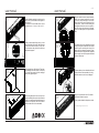
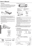
installation guide
user manual
DUPLO
KIT
conexión organizada
organized connection
user manual
WALL MOUNT
Insert a flathead screwdriver in the slots on the
side of the covers indicated in the diagram to
lever them off.
To remove the voice and data cover, use the
screwdriver as a lever at the top of it.
01
1-2
user manual
05
2
Once the cables have been inserted inside the
profile, you can screw the duplo kit to the wall.
To do this, position the duplo kit so that the
holes in the wall line up with the anchor holes
in the profile. Once the screw heads pass
through the anchor holes, move the profile to
one side so that when the screw is tightened,
it sits on the narrow part of the profile anchor
hole.
1
Once you have removed the covers, you can
access the inside of the
the profile.
profile. Mark
Markthe
thecentre
centre
of the
the holes
holes in
in order
order to
to later
later fix
fix itit to
tothe
thewall.
wall.
The holes where the
the profile
profile will
will be
be fixed
fixed are
are
indicated in diagram 2.
02
03
2
After marking them, drill the holes. Then insert
the rawlplugs in the holes made. The next step
is to screw the screws inside the rawlplugs
without fully tightening them.
CONNECTING THE ELECTRIC PART
The cables that you have inserted at the back
of the profile must be connected to the terminal
inside the profile, matching the colour of the
cables with those already connected. Phase,
Earth and Neutral. If the profile has a regulated
power supply, there will be separate terminals
for these connections.
.
06
CONNECTING VOICE AND DATA
The data cables you have inserted at the back
of the profile must be connected to the voice
and data connectors, as shown in diagram 7.
07
1
A
voice and data cable
04
Data
Electric
MAKING THE CONNECTIONS
Before fixing the duplo kit to the wall, you must
insert the cables that come from the connection
panel on the wall through the cable channel at
the back of the duplo kit. One is for the electric
cable and the other is for the data cable.
08
Now you must place the cover of the anchor
system and connection system.
For any queries related to the product, contact:
[email protected]