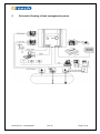
1
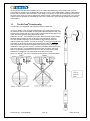
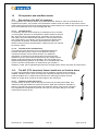
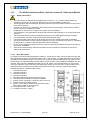
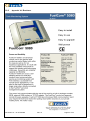
® FuelCom 5080 Installation & User manual Automatic Tank Gauging System Document no.: 15-CFC09026 Rev. B Page 1 of 34 1 Summary .......................................................................................................................................... 4 1.1 FC5080 System features: ........................................................................................................ 4 1.2 Software functions: .................................................................................................................. 4 2 Schematic Drawing of tank management system ............................................................................ 5 3 FuelCom Assembly Drawing........................................................................................................... 6 ® 3.1 Configuration: .......................................................................................................................... 7 3.2 Safety note:.............................................................................................................................. 7 4 The AC Adapter ................................................................................................................................ 7 5 Installation of the Control Unit .......................................................................................................... 8 5.1 Mounting location..................................................................................................................... 8 5.2 Installation of the control unit ................................................................................................... 8 5.3 Adding a New Module to FuelCom 5080 ................................................................................ 9 5.4 Module installation procedure.................................................................................................. 9 ® 6 Wiring the Control unit .................................................................................................................... 10 7 FuelCom Grounding Bar (Ex zone). ............................................................................................. 11 ® ® 7.1 Assembly of Grounding bar inside FuelCom ....................................................................... 11 7.2 Installation of the cables into the cable glands. ..................................................................... 12 7.3 Connection to IS- ground. ...................................................................................................... 12 8 Wiring of the control unit to external devices ................................................................................. 13 9 Planning Sensor and Probe Installation ......................................................................................... 14 9.1 New sites ............................................................................................................................... 14 9.2 Existing sites .......................................................................................................................... 14 9.3 Intrinsically safe wiring issue ................................................................................................. 14 9.4 Grounding issue..................................................................................................................... 14 9.5 Wiring conduit safety issue .................................................................................................... 14 9.6 Cable ..................................................................................................................................... 14 9.7 4tech installation cable .......................................................................................................... 15 9.8 Sealing the conduits .............................................................................................................. 15 10 Probe and sensor introduction ................................................................................................... 16 ® 10.1 FuelBar 410/420 and P44 probe ........................................................................................... 16 10.2 MiniBar ................................................................................................................................... 16 10.3 FuelBar probes, range of variation: ...................................................................................... 16 10.4 Differences in FuelBar 410/420 probes: ............................................................................... 17 10.5 Separate overfill prevention sensor: ...................................................................................... 17 ® ® ® 11 The AirTrap Functionality. ........................................................................................................ 18 12 Oil separator and overflow sensor. ............................................................................................ 19 12.1 Description of the KVF oil separator ...................................................................................... 19 12.2 The NVF (PTC thermistor) Sensor installed as an Overflow Alarm. ..................................... 19 13 ® Modules of FuelCom 5080 ........................................................................................................ 20 Document no.: 15-CFC09026 Rev. B Page 2 of 34 13.1 General safety advice ............................................................................................................ 20 13.2 The AD424 Intrinsically Safe - Galvanic Isolated 4...20mA Input Module ............................ 21 13.3 The RE202R2 Intrinsically Safe - Galvanic Isolated Relay Output Module........................... 22 13.4 The PT100R1 Oil Separator interface module ...................................................................... 23 14 Wiring Probes and Sensors to the Control unit ......................................................................... 24 14.1 Site wiring preparation. .......................................................................................................... 24 14.2 General safety issue .............................................................................................................. 24 14.3 Installation of hardware ......................................................................................................... 24 14.4 Additional Equipment ............................................................................................................. 24 15 ® Setting up FuelCom 5080 ......................................................................................................... 26 15.1 Configuration and calibration using FuelWin ....................................................................... 26 15.2 Using FuelCom 5080 Front Panel ........................................................................................ 26 15.3 Description of System Alarms ............................................................................................... 26 15.4 Front panel <SERVICE MENU> reference ........................................................................... 26 16 ® ® Appendix I - VII .......................................................................................................................... 28 16.1 Appendix I: Density table. ...................................................................................................... 28 16.2 Appendix II: Installation plan. ................................................................................................. 29 16.4 Appendix III: Technical specifications for FuelCom 5080. ................................................... 30 16.5 Appendix IV: Declaration of Conformity. ............................................................................... 31 16.6 Appendix V: Product Quality Assurance Notification............................................................. 32 16.7 Appendix VI. Verification form for intrinsically safe installation of FuelCom 5080 ................ 33 16.8 Appendix VII. Brochure. ......................................................................................................... 34 ® Document no.: 15-CFC09026 Rev. B Page 3 of 34 1 Summary Thank you for choosing a 4tech AS product ® The FuelCom 5080 is based on a well proven and advanced technology, and designed to give a high performance solution for environmental and inventory management needs. In order to comply with present and future requirements, the system has a flexible and modular architecture which is configurable on site. ® The FuelCom 5080 is intended for Ex-environment, and it is easy to install and use. It operates with a single point push and scroll button, or via RS232 communication ports. Remote communication is available via a built in analogue modem, or external GSM modem, or an Ethernet adapter. ® ® With the FuelWin software installed on your back office computer, FuelCom 5080 gives a new meaning to the words “Tank Management”. The 4tech hosted and web based server software collects data from any number of tank management systems in order to generate reports for planning the distribution, generating historical reports and managing alarms. The server software is an optional subscription service in combination with access to the 4tech support centre. For this and other web applications, contact 4tech AS. 4tech AS remains focused in providing quality monitoring systems for liquids, and look forward to help you with your present and future needs. 1.1 1.2 FC5080 System features: Up to 8 tanks Integrated standard analogue modem Easy upgradeable modular system 4x RS232 Com ports RS485 Local bus, support for 4 modules (optional 8) Monitoring of oil separator 4x40 character display, with user-friendly icon based menus, LED backlight and contrast control Scroll wheel and push buttons for navigation User data stored in data flash Local visual LED and audible alarm External 80 columns thermal printer (optional) Real-time clock Software upgrade through built-in bootloader Truck Driver Display (optional) 12Vdc power input, auto power save Ambient temperature sensor Optional external Ethernet adapter or ISDN modem Optional external GSM modem Software functions: Product level Product temperature Water detection. Automatic Leak detection. Programmable alarm limits. Automatic delivery reports. Document no.: 15-CFC09026 Rev. B Automatic 24 hour inventory reports Volume reports POS interface Alarm History Tank calibration Periodic reports Page 4 of 34 2 Schematic Drawing of tank management system Document no.: 15-CFC09026 Rev. B Page 5 of 34 FuelCom® Assembly Drawing 3 1. COM 4 FuelWin interface 2. COM 3 Selectable POS protocol 3. COM 2 GSM modem, ISDN,TCP/IP or FuelWin 4. COM 1 External printer /FuelWin 5. RJ45 modem line input 6. Power connector 7. Cable attachment clips 8. Up to 8 module slots 9. LCD 40x4 character 10. Navigating wheel 11. Module access door 12. Cable inlet The following pos systems are known to utilize the FuelCom interface protocol and be connected to com port 1,2 or 4: Dresser Wayne, Nucleus Doms, PSS 5000 The FuelCom interface protocol documentation (FIP) is available on request. Document no.: 15-CFC09026 Rev. B Page 6 of 34 3.1 Configuration: ® The FuelCom 5080 is a microcomputer based controller for tank gauging. Inside there are 4 slots for signal interface modules, where the number of preinstalled modules may vary. It is possible to order the FuelCom 5080 with AD424 modules for probe signal inputs, or special modules for oil separator or relay signal outputs. These modules are all intended for use together with equipment in explosive areas, and they are ATEX approved. 3.2 Safety note: This symbol is used when the information is important for safety of the installation. 4 The AC Adapter Each FuelCom® 5080 controller is delivered with an AC power adapter. The adapter handles input voltage spans from 100-240VAC. The output volt is a fixed 12 VDC / 18W. 12VDC output must not be exceeded. The power adapter can be delivered with two different plug types: Euro-plug UK-plug Always use the power supply which is delivered together with the controller unit! This applies also if a controller unit is replaced. Document no.: 15-CFC09026 Rev. B Page 7 of 34 5 Installation of the Control Unit 5.1 Mounting location Note: The controller must be installed outside the Ex area! Although the FC5080 is intended for Ex-applications, the controller itself cannot be placed in a hazardous zone. An indoor location in a safe area must be chosen, protected from vibration and extreme temperatures. The operating temperature range of the controller is 0 to 50 °C. The mounting location must be able to support the weight of the control unit, which fully equipped could exceed 4 kg. The control unit should not be mounted more than 1 metre from an AC power outlet. When deciding the actual installation place, please remember the space needed for probe sensor cables and communication cable for back office system. For outdoor installation the control unit must be installed in a cabinet which protects the control unit from exposure to rain, humidity, temperature below 0 °C or above 50 °C, etc. Outdoor locations must be chosen outside the hazardous area. Please consult local regulations if necessary. As an option you may order an approved enclosure with built in heater from 4tech. 5.2 Installation of the control unit Install the control unit with four screws using the pattern shown in Figure 01. Screws are provided with each control unit. Fig. 01 Document no.: 15-CFC09026 Rev. B Page 8 of 34 5.3 Adding a New Module to FuelCom®5080 ® The flexible, modular system architecture in FuelCom 5080 makes it easy to add new functionality for individual requirements. By adding a new module to a free slot inside the control unit, new functions are ® available. The standard FuelCom 5080 has 4 slots for modules, but it is possible to order 5080 with up to eight modules inside the control unit. If necessary, the full duplex RS485 local bus inside the ® FuelCom 5080 can be expanded to cover a number of maximum 32 modules on the bus line. In this case, the extra modules have to be installed externally. For further information please contact 4tech AS. The following three standard modules are available, all ATEX approved: The AD424 is an intrinsically safe galvanic isolated 4 channel 4…20mA input module, combined with an intrinsically safe power supply for power feeding to the probes. This module makes it easy to ® connect FuelCom 5080 with any current loop transmitter. If more than one AD424 module is added ® to the FuelCom 5080 control unit, each module has to be addressed using the DIP-switches. The RE202 is an intrinsically safe galvanic insulated relay output module, which provides the user with four independent normally closed relay outputs. Each output is software controlled and can be programmed to trig on a specified event. If more than one relay module is added to the ® FuelCom 5080 control unit, each module has to be addressed using the DIP-switches. The PT100 is an intrinsically safe galvanic isolated sensor input module, combined with an intrinsically safe power supply for power feeding. The module provides the user with two independent channels of interface to the sensors NVF and KVF. The data output from the module is presented on the RS485 local bus. With the PT100 protocol implemented on a host computer data can easily be polled through the local bus interface. ® Recommended layout with only FuelBar 410/420 probes: Slot 1: Tank 1 & 2 Slot 3: Tank 5 & 6 Slot 2: Tank 3 & 4 Slot 4: Tank 7 & 8 5.4 Module installation procedure ® Turn off the power to the FuelCom controller. Open the access door on the control unit. Before inserting the module circuit board into the housing, the DIP switches must be set correctly. (see the user manual for the module) The module circuit board slides into a guide track inside the housing, and plugged into the module housing socket. Make sure the board enters the edge connector properly. Push the module into locked position. Connect the equipment to the terminals on the module in accordance with the wiring diagram (see the wiring section or the datasheet for the module). Whenever Ex modules are installed, observe the national safety rules and regulations for the prevention of accidents as well as the safety instructions listed in the datasheet of each module. Turn on the power and check the module for proper operation. Document no.: 15-CFC09026 Rev. B Page 9 of 34 6 Wiring the Control unit 1. Power inlet connector. 3. COM1. Communication port to the back ® office computer, where the FuelWin software is installed. 4. COM2. Communication port for remote communication, like ISDN modem, GSM modem or other equipment. 5. COM3. Dedicated communication port for Point Of Sale interface (POS) Check the software manual for proper protocol. 6. COM4. Communication port for printer interface. 7. Cable inlets for sensor wiring (10 ea). 2. Line input for the built in analogue modem. PIN No. 2 3 7 8 COM1 RxD TxD RTS CTS Document no.: 15-CFC09026 COM2 RxD TxD Not Supported Not Supported Rev. B COM3 RxD TxD Not Supported Not Supported COM4 RxD TxD RTS CTS Page 10 of 34 7 FuelCom® Grounding Bar (Ex zone). In order to comply with Ex regulations, the screen on the ® blue cable which connects the FuelCom modules with the probe (EX zone) must be connected to IS-ground at the ® FuelCom side. The grounding Bar has 10 threads for M16 cable glands with connection facility for the cable screen, and it is prepared for a grounding cable to be connected at each side. The grounding cables from the Bar must be connected directly to separate IS-ground. It shall not be connected to ordinary protection ground. Important notice! In order to comply with Ex safety regulations, the screen of the blue installation cable shall NOT be connected to the cable screen of the probe inside the Scotchcast connection joint. The grounding kit contains the following items: 7.1 1 pc. Copper grounding bar with threads for 10 pc. of M16 cable glands. 4-10 pcs. M16 Cable glands with internal contacts for coax screen (quantity depending on number of modules preinstalled). 1 pc. Label kit for tank numbering 1-8. Blinding plugs. Assembly of Grounding bar inside FuelCom® Please follow the instructions carefully! Please remove all cables and rubber plugs. The copper bar is assembled by inserting it inside the FuelCom cabinet as shown. The screw terminal for the IS-grounding cable faces upwards. The copper bar is fixed with the cable glands only. Use one cable gland at the end first, then the remaining. Use the blind plugs to close the remaining openings. The cable gland is inserted using a M20 wrench. (In some markets, the insulation washers shown on the pictures are not in use). Document no.: 15-CFC09026 Rev. B Page 11 of 34 7.2 Installation of the cables into the cable glands. After the grounding bar is placed, the cable installation can begin. Please do not use the left most and right most bushing for the tank installation cables. These are reserved for the grounding cable (ISground). Inside each cable gland, there are four contact springs for connecting the cable screen. The cable insulation must therefore be removed on the section where the contact facility appears. Please follow the guidelines carefully. Insert the cable through the gland as far as necessary for connection to the proper module. Mark the cable at the end of the cable gland with an ink pen. (A). Retract the cable approx. 4 cm and mark the cable again (B) at the end of the gland. Make a new mark C in the middle between the two marks A and B. Remove the outer insulation on the cable between B and C in order to expose the screen. Install the cable again in the first position A. The screen of the coax cable is now grounded inside the cable gland. Tighten the screw on the gland to fix the cable. The cable screen shall not be in contact with any other parts inside the cabinet. At the module end, the screen should be cut or insulated. If the screen is exposed, make sure it is insulated properly with tape. The cables to other tanks are installed in a similar way. One cable through one cable gland only! The number of cable glands needed is the same as number of cables plus two for ground cables. Each tank cable is marked with its respective tank number using the label kit. (Tank number 1 - 8). 7.3 Connection to IS- ground. The grounding cables to IS- ground is installed through the left most and right most cable gland directly to the grounding screw on the copper bar. Both connections should be used. The recommended 2 dimension of the cable is 4-6 mm . The colour used is green / yellow also for IS- Ground. The grounding shall be possible to verify by measuring the resistance in the two ground cables. This is done by opening the circuit at IS-ground an measure a loop resistance in the grounding R<1 ohm Document no.: 15-CFC09026 Rev. B Page 12 of 34 8 Wiring of the control unit to external devices ® This configuration table refers to the output COM3 on the FuelCom 5080. Serial POS interface configuration table: ® FuelCom 5080 Marketer Pin No. 2 6 Pin No. 3 13 Pin No. 5 8 Delta 2 3 7 Description of the most common RS-232/ V.24 signals. Description of connection between FuelCom ®5080 and PC (FuelWin) or PetroPoint. ® FuelCom 5080 8.1.1 9-Pin D-Sub (Female) Pin 2 Pin 3 Pin 5 Connect to to to FuelWin 9-Pin D-Sub (Male) Pin 3 Pin 2 Pin 5 Description of connection between FuelCom ®5080 and Modem (FuelWin/MCD/NKS). ® FuelCom 5080 8.1.2 9-Pin D-Sub (Female) Pin 2 Pin 3 Pin 5 Pin 7 Pin 7 Connect to to to to to Modem 25-Pin D-Sub (Male) Pin 3 Pin 2 Pin 7 Pin 4 Pin 20 Description of connection between FuelCom ®5080 and DELTA (DELTA-Statoil/DELTA-Jet). ® FuelCom 5080 8.1.3 9-Pin D-Sub (Female) Pin 2 Pin 3 Pin 5 Connect to to to DELTA 9-Pin D-Sub (Male) Pin 2 Pin 3 Pin 7 Description of connection between FuelCom ®5080 and MARKETER (YX-MARKETER). ® FuelCom 5080 8.1.4 9-Pin D-Sub (Female) Pin 2 Pin 3 Pin 5 Connect to to to MARKETER 15-Pin D-Sub (Male) Pin 6 Pin 13 Pin 8 Description of connection between FuelCom ®5080 and Printer ® FuelCom 5080 8.1.5 9-Pin D-Sub (Female) Pin 2 Pin 3 Pin 5 Document no.: 15-CFC09026 Connect to to to MARKETER 9-Pin D-Sub (Male) Pin 2 Pin 3 Pin 5 Rev. B Page 13 of 34 9 Planning Sensor and Probe Installation 9.1 New sites To calculate conduits and wiring lengths, use a planning diagram. Prior to site paving, the contractor must ® diagram all proposed conduits running between the FuelCom 5080 Control unit’s intended location, and its deployed sensors and probes. This document is kept together with other documents at the site. During the site planning process of Ex installations, the applicable national safety standards and the general technical rules must be observed. The illustration in the next chapter shows a simplified site deployment of probes and sensors. The location of probes and sensors will vary from site to site. 9.2 Existing sites ® If the FuelCom 5080 system is being retrofitted at a site with no cable conduits or manholes, three options are given: 1. Dig out trenches in the forecourt to run rigid conduit pipes out to sensors and probes. 2. Cut grooves in the pavement, run direct trenches to these devices, and then seal the cable groove. 3. A combination of the two methods above. The same planning process and the same standards regarding safety of Ex-installations have to be carried out as for new sites. 9.3 Intrinsically safe wiring issue ® The output power from the intrinsically safe galvanic isolated modules inside the FuelCom 5080 is limited to a safe level, and normally it is not possible to ignite fuel. But the capacitance and inductance in the installation cable may store energy that might ignite fuel. Therefore, the energy calculation diagram must be filled out in order to verify that the length of the cable is within the safety limits (example form in appendix VI). Do not exceed the specified data of the equipment installed in the hazardous area. 9.4 Grounding issue Because there is a fully galvanic isolation between the Ex side and the safe side of the modules, no time demanding ground bus has to be installed, like in old systems with zener barriers. Only the screen of the installation cable must be connected to ground using the grounding bus bar (see section 7). The grounded screen of the blue* installation cable must NOT be connected to the screen of the tank probe. In that case the safety of the installation is violated. 9.5 Wiring conduit safety issue ® To maintain the intrinsically safe integrity of the FuelCom 5080 system, sensor and probe conduits can share the same trenches as power conduits, but the intrinsically safe sensor and probe wiring can NOT share the same conduit with any other wiring. Where power conduits and conduits with intrinsically safe wiring meets in a junction manhole, the intrinsically safe wiring should be separated from the power cables with a safe distance. This to prevent induced current to be transformed. Such separation between cables is important when power cables and intrinsically safe cables share the same suspension bridge. Please follow applicable national safety standards regarding Ex installations. 9.6 Cable The extension cable between probe and controller should fulfil the following requirements, such as (but not limited to): Oil resistance according to DIN ISO, 6722 part 1 par. 4.11, DIN VDE, 0472 part 803 test mode B. Petrol resistance according to DIN, ISO 6722 part 1 par 4.12. PVC self-extinguishing and flame retardant according to DIN VDE, 0482 part 265-2-1/EN 50265-21/IEC 60332-1 (equivalent DIN VDE 0472 part 804 test method B). Special PVC core insulation to DIN VDE 207 Cores color coded according to DIN 47100 Color blue RAL 5015 * Note! According to ATEX / Ex regulations, the colour of intrinsic safe cables shall be blue. Document no.: 15-CFC09026 Rev. B Page 14 of 34 9.7 4tech installation cable We recommend using the especially made 4tech cable. Provided that 4tech cable type LIYCYöb KEA-030 is used, the values below apply for the specified length. If another cable is used, the calculations must be done manually. Change cable parameters according to datasheet for the actual cable. Length Resistance. Rc Capacitance. Ccab Inductance. Lcab 200 15,12 24 0,14 300 22,68 36 0,21 400 30,24 48 0,28 500 37,8 60 0,35 600 45,36 72 0,42 700 52,92 84 0,49 800 60,48 96 0,56 900 1000 68,04 75,6 108 120 0,63 0,7 The theoretical limit of installed cable length for gas group IIA (gases of hydrocarbons) is much longer than indicated above. For practical installations, the table is limited to 1000 metres. The actual length meters should be used in every calculation and documentation. For control, measure the feeding voltage from the output of the AD424 module for each channel. Fill in all data in the verification form (appendix VI), and sign. 9.8 Sealing the conduits All cable conduits must be sealed with flame-retardant filler after the cable work is done. Document no.: 15-CFC09026 Rev. B Page 15 of 34 10 Probe and sensor introduction 10.1 FuelBar®410/420 and P44 probe ® The FuelBar 410/420 and P44 are high performance analogue pressure transmitters for level measurement in storage tanks, above ® or underground. Together with FuelCom 5080, this forms a unique ® inventory system for service stations. The FuelBar and P44 probe is based on a hydrostatic measuring principle. The pressure at the bottom of the tank caused by the column of liquid height is proportional to the analogue output signal. These probes also provide continous temperature indication in a separate signal loop. The ® FuelBar 410/420 is equipped with an on/off water detection float which triggers at 35 mm. water level. The pressure transducer is delivered for gauge pressure ranges from 0... 160 mbar to 0... 1 bar. Other measuring ranges are available on request. This measuring principle has a wide measuring range which spans ® from 0 to 20 metres. The FuelBar 410/420 is proved to be accurate and will function effective as an early warning system for leaks. The probe will continuously update your site management system with highly accurate inventory information concerning product level, temperature and water indication. Full ATEX approval for sone 0. 10.2 MiniBar The customer specific, submersible pressure transducers MT-30 are available for gauge pressure ranges from 0... 100 mbar to 0... 20 bar. Other measuring ranges are available on request. The most common applications are in the areas of medical devices and for hydrostatic level measurement. Due to the small build (Ø22mm) the transducers could be used in a large variety of applications. 4tech has the know-how to provide solutions for the most diverse applications, adapting both the electrical and the structural aspects of the pressure transducer to your specific application. Full ATEX approval for sone 0. Typical users are heating oil, lubricant and diesel customers. 10.3 Ex Marking: ATEX: II1G EExia IIC T4 NEMKO 99 ATEX 219 Ex Marking: ATEX: II 1/2 GD EEx ia IIC T6 ISSeP07ATEX003X FuelBar®probes, range of variation: ® The FuelBar 410/420 can be delivered in many variants and different pressure ranges: ® ® A) With AirTrap and aluminium pipes: B) With AirTrap , aluminium pipes and PTC (overfill prevention): Typically: Diesel and petrol No ethanol additives Max tank height, 320 cm Without overfill prevention With water detect float Document no.: 15-CFC09026 Typically: Diesel and petrol No ethanol additives Max tank height, 320 cm With overfill prevention With water detect float Rev. B Page 16 of 34 ® ® C) With AirTrap and SS316L pipes: D) With AirTrap , SS316L pipes and PTC (overfill prevention): Typically: Diesel, petrol, E85 Ethanol additives, OK Max tank height, 320 cm Without overfill prevention With water detect float Typically: Diesel, petrol, E85 Ethanol additives, OK Max tank height, 320 cm With overfill prevention With water detect float E) Without pipes, but with anchor: ® Can also be delivered with Airtrap F) Without pipes and float, but with anchor: ® Can also be delivered with Airtrap Typically: Diesel, petrol, E85 Ethanol additives, OK Max tank height, 2.500 cm Without overfill prevention With water detect float 10.4 Typically: ADBlue, water, other liquids Ethanol additives, OK Max tank height, 2.500 cm Without overfill prevention Without water detect float. Differences in FuelBar®410/420 probes: ® The FuelBar 410 and 420 probes are identical, except the temperature loop calibration range. ® ® The range for FuelBar 410 is -50 - + 50 ºC, and the new FuelBar 420 range is -20 - + 80 ºC This must be observed when replacing an older FuelBar 410 with the new 420. In this case it is necessary to adjust the temperature readout via the FuelWin software. 10.5 Separate overfill prevention sensor: The overfill prevention system is also available as a retrofitable solution. The overfill sensor can be mounted directly through the flange, using a proper nipple. The length of the sensor can be adjusted on site, in order to define the exact overfill limit. The Overfill Prevention Control System (OPC) is delivered as a separate solution. It provides a secure means of protecting the environment. Tanker trucks will effectively be stopped in overfilling underground or above ground tanks. The system is a self-checking Document no.: 15-CFC09026 Rev. B Page 17 of 34 security device that prevents overfilling of up to 8 tanks simultaneously, which means that on most petrol stations, all tanks can be filled at the same time. The in-truck OPC System (option) is also able to provide the truck driver with information of the ullage of each tank via the tank level gauge system and the truck driver does not need to gauge each tank manually. These features not only give a very secure system but also optimize the unloading process of the tank trucks, with several minutes saved at each petrol station. 11 The AirTrap® Functionality. ® The AirTrap is a registered and patented product of 4tech AS. In order to obtain a very accurate measurement, it is a benefit to have the air reference tube of the FuelBar 410/420 probe placed inside the tank. But if the air tube is filled with any liquid, it will cause permanent damage to the probe and make it report wrong liquid level height. ® Using the AirTrap , it is possible to have the reference tube located inside the tank without having the risk of filling the tube with liquid. With the ® AirTrap installed properly it is not possible for any liquid to reach the ® reference tube of the probe. As soon the AirTrap is emerged vertically into ® any liquid, an air pocket is being held inside the top of the AirTrap pipe, and will prevent any liquid from reaching the reference tube. During the ® installation, make sure the AirTrap is properly installed, and that the lower ® end of the AirTrap is not installed below the lower end of the riser pipe. Before the probe is lowered into the tank, secure the cable with a strain relief device. Otherwise, you might drop the probe into the tank. ® Note: The AirTrap can only be exposed to the liquid in a vertical position. Document no.: 15-CFC09026 Rev. B Page 18 of 34 12 Oil separator and overflow sensor. 12.1 Description of the KVF oil separator An oil separator is a container where oil products like petrol, diesel oil, motor oil, and waste oil are separated from water. The purpose of this separation is both to clean the water of oil products, and to avoid polluting the environment or the purifying plant. Another purpose is to collect the oil products so that they can be destroyed in an environmentally safe way. 12.1.1 The KVF Sensor Theoretically, the KVF sensor requires no maintenance, as it contains no moving parts. But since an oil separator contains all kind of oils and fats, there may be a risk that the sensor, eventually, may be covered with a layer of some indeterminable substance. This may enhance the risk of false alarms. Accordingly, the sensor should be cleaned when the separator is emptied. The sensor itself should not need to be tested, but this may be a good precaution. Please see the user manual for the KVF sensor. 12.1.2 The KVF Sensor and Emulsion There may be cases where the oil is not separated because an emulsion has been formed. There are two kinds of emulsion, mechanical emulsion and chemical emulsion. For additional information, or if there is any chance that the oil is has not been separated from the water when the liquid enters the sewage system, please contact the supplier of the separator. The KVF sensor is not capable distinguishing between oil and water in an emulated state, and it is the user who is responsible, no matter which type of liquid or separator is used, that no polluted liquid enters the sewage system, which may harm the environment. 12.2 The NVF (PTC thermistor) Sensor installed as an Overflow Alarm. To get a high level alarm before overflow of the oil separator, the NVF sensor should be installed. The NVF sensor works according to the thermal principle where a PTC resistor is placed inside a tube, is heated. When the sensor is submerged in liquid, the PTC resistor is cooled, which results in an alarm signal to the central unit. 12.2.1 Inspection of the NVF sensor. The NVF sensor is robust, and all oil products become low viscosity when hated. This reduces the risk that substances stick to the sensor. When the container is emptied it is always a good idea to inspect the system and check the sensor. If the sensor is lowered to a height which corresponds to the hole in the side of it, the alarm will go off, and this means that the sensor is OK. Document no.: 15-CFC09026 Rev. B Page 19 of 34 Modules of FuelCom®5080 13 13.1 General safety advice Please study these safety advices carefully. 13.1.1 Shielding the Data Cables The data cables are shielded using a Grounding Bar with special ground Glands. Use shielded twisted pair cables. Connect the cable shield to ground on one side (FuelCom side) only. 13.1.2 Technical Data The modules are only to be used as associated with an intrinsically safe apparatus. All the instructions and conditions in the approval for the application area of the module have to be respected. Se separate user manual for each module. 13.1.3 Conformity with Standards These intrinsically safe modules have galvanic insulation, and meet the requirements of EN50014 and EN50020. This product has been designed, manufactured and tested in accordance with the ATEX regulations. The intrinsically safe outputs from these products are suitable for zone 0, 1 and 2. 13.1.4 Installation/Start up When installing and operating electrical apparatus, the applicable national safety standards and the general technical rules for maintenance and inspections must be observed. Transportation and storage in original package only! Prior to starting up, the following checks should be performed and compared with the technical data: Are the proper operating conditions being respected? Check the correct polarity of all connections. Check that there are no impermissible voltage feeding back into the output circuit during start up Measure the total input/output load and compare with the maximum permissible load in the data sheet. ® Make sure that the cable screen is grounded only at the FuelCom side. Check the power supply for correct values. 13.1.5 Connection Type Intrinsically safe (I.S.) circuits and non-I.S. circuits have to be installed separately. “Combicon” Screw-clamp terminals: Permissible cable cross sections: 0.2mm² to 2.5mm² (24 AGW to 14 AGW). Recommended cable cross section: 0.4mm²- 0.5mm² (21 AWG to 20 AWG) 13.1.6 Service Information In case of unusual behaviour of the device, please check cables and all external connections. Overloading of the device must be avoided. Repairs of the explosion protection are only to be carried out by 4tech AS or a qualified electrician in compliance with the applicable national standards. For replacements of spare parts, only original 4tech AS replacements parts are to be used. Defect units or modules must be returned to 4tech AS for repair, no other repair shops are allowed to repair Ex products made by 4tech AS. 13.1.7 Disposal/Recycling Observe the national regulations for disposal and recycling. The material of the housing is Polyamide (PA) Observe the national safety rules and regulations for the prevention of accidents as well as the safety instructions given: Document no.: 15-CFC09026 Rev. B Page 20 of 34 13.2 13.2.1 The AD424 Intrinsically Safe - Galvanic Isolated 4...20mA Input Module Safety instructions The input module is designed for Ex applications in zones 0, 1 or 2, but the module itself is not suitable for mounting in an explosive atmosphere, it must be installed in a safe area. The temperature class and explosion group as well as the special conditions marked on the product have to be respected! According to the EC-type examination, the following limits of Ex-Protection must not be exceeded: AD424: Uo=24,74 Io=90mA Po=0.65W Modification of the device or changes of its design are not permitted! The installation is only permitted in housings with minimum IP20 protection or in closely supervised systems. The device has to be used for its intended purpose and in an undamaged and proper condition. For replacement, only 4tech original replacement parts must be used. Components which need repair must be shipped to 4tech AS. Unauthorized repair is forbidden. Service that will influence on the explosion protection is only to be carried out by 4tech or a qualified Ex electrician in compliance with the applicable national standards. Prior to its first start-up the device has to be checked in accordance with the instructions as listed in the section “installation”. Observe the national safety rules and regulations for the prevention of accidents as well as the safety instructions given. 13.2.2 Brief Description The AD424 is an intrinsically safe galvanic isolated 4…20mA input module, which provides the user with four independent channels of transmitter power and 4…20mA inputs. The data output from the module is presented on the RS485 local bus. If more than one module of AD424 is added to the bus system, each module has to be addressed using the DIP-switch on each module. (See the AD424 installation and user manual). Each channel is labelled with letter from A to D. When a loop powered device is connected to one of the channels, a red led is set to indicate that the polarity of the connection is right. A flash on the green (RX) LED is indicating a successful transmission from a host computer. A green LED (PWR) indicates that power is applied to the module. 1. 2. 3. 4. 5. 6. 7. 8. 9. LED Red channel B LED Red channel A LED Red channel C LED Red channel D LED Green RX transmission received from host LED Green power indicates that power is applied Snap in foot for mounting on 35mm din rails. (EN 50022) Printed circuit board inside housing Button on each side to release the top of the housing. Pull to get the PCB out of the housing 10. IS Screw terminal on each side 11. Local Bus connector, 10pole. Document no.: 15-CFC09026 Rev. B Page 21 of 34 13.3 The RE202R2 Intrinsically Safe - Galvanic Isolated Relay Output Module 13.3.1 Safety instructions The module is designed for Ex applications in zones 0, 1 or 2, but the module itself is not suitable for mounting in an explosive atmosphere, it must be installed in a safe area. The temperature class and explosion group as well as the special conditions marked on the product must be respected! According to the EC-type examination, the following limits of Ex-Protection must not be exceeded: RE202R2: Ui/Uo<60V, Ii/Io<500mA. Modification on the device or changes of its design is not permitted. The installation is only permitted in housings with minimum IP20 protection or in closely supervised systems. The device has to be used for its intended purpose and in an undamaged and proper condition. For replacement, only 4tech original replacement parts must be used. Components which need repair must be shipped to 4tech AS. Unauthorized repair is forbidden. Service that will influence on the explosion protection is only to be carried out by 4tech or a qualified Ex electrician in compliance with the applicable national standards. Prior to its first start up, the device must be checked in accordance with the instructions as listed in the section “installation”. 13.3.2 Brief description The RE202R2 is an intrinsically safe galvanic insulated relay output module, which provides the user with four independent normally closed relay outputs. Each output is software controlled and can be programmed to trig on a specific event. The output is set by sending a command through the local bus from a host computer. Whenever an output is activated a red LED is also set to indicate the activated output. A flash on the TxD LED is indicating a successful transmission from a host computer. It is possible to set the RE202R2 relay module into manual operation by pressing the “SEL” button (Se table in the RE202R2 module user manual). This option is time controlled and the module will resume normal operation after 2 min. A green LED indicates that power is applied to the module. 1. 2. 3. 4. 5. 6. 7. 8. 9. LED Red relay C LED Red relay A LED Red relay D LED Red relay B IS Screw terminal on each side Local Bus (Pin #2) Printed circuit board inside housing Snap in foot for mounting on 35mm din rails. (EN 50 022) Button on each side to release the top of the housing. Pull the PCB out of the housing. 10. LED Green RxD indicates communication. 11. LED Green PWR indicates applied power. 12. SEL button for manual operation Document no.: 15-CFC09026 Rev. B Page 22 of 34 13.4 The PT100R1 Oil Separator interface module 13.4.1 Safety instructions The input module is designed for Ex applications in zones 0, 1 or 2, but the module itself is not suitable for mounting in an explosive atmosphere, it must be installed in a safe area. The temperature class and explosion group as well as the special conditions marked on the product have to be respected! According to the EC-type examination, the following limits of Ex-Protection must not be exceeded: PT100R1: Uo=23.64 Io=366mA Po=2.16W Modification of the device or changes of its design are not permitted. The installation is only permitted in housings with minimum IP20 protection or in closely supervised systems. The device has to be used for its intended purpose and in an undamaged and proper condition. For replacement, only 4tech original replacement parts must be used. Components which need repair must be shipped to 4tech AS. Unauthorized repair is forbidden. Service that influences on the explosion protection is only to be carried out by 4tech or a qualified electrician in compliance with the applicable national standards. Prior to its first start-up the device has to be checked in accordance with the instructions as listed in the section “installation”. Observe the national safety rules and regulations for the prevention of accidents as well as the safety instructions given. 13.4.2 Brief Description The PT100R1 is an intrinsically safe galvanic isolated sensor input module, which provides the user with two independent channels of interface to the sensors KVF and NVF. The data output from the module is presented on the RS485 local bus. With the PT100R1 protocol implemented on a host computer data can easily be polled through the local bus interface. If more than one module of PT100R1 is added to the bus system, each module has to be addressed. (See user manual of the PT100 module). The two channels are labelled with letters A and B. The KVF sensor must be connected to channel A, and the NVF sensor must be connected to channel B. When a sensor is connected to one of the channels, a yellow led is set to indicate that the sensor is enabled and the polarity of the sensor connection is made correct. The NVF sensor /thermistor need a 20…60 sec. of warm up period before it is enabled. During the warm up period the red led on channel A starts to blink. If an alarm condition occurs, on one of the sensors, a red led is set to a steady state. A flash on the green (RX) LED is indicating a successful transmission from a host computer. A green LED (PWR) indicates that power is applied to the module. 1. 2. 3. 4. 5. 6. 7. 8. 9. LED Red/Yellow channel B+ LED Red channel BLED Red/Yellow channel A+ LED Red channel A LED Green RX transmission received from host LED Green power indicates that power is applied Snap in foot for mounting on 35mm din rails. (DIN EN 50 022) Printed circuit board inside housing Button on each side to release the top of the housing. Pull to get the PCB out of the housing 10. IS Screw terminal on each side 11. Local Bus 10pol. Document no.: 15-CFC09026 Rev. B Page 23 of 34 14 Wiring Probes and Sensors to the Control unit 14.1 Site wiring preparation. This section assumes that all preliminary site preparation is completed and that field wiring from the control unit to the probes and sensors junction boxes are in place. 14.2 General safety issue Wiring of intrinsically safe equipment in hazardous areas must be carried out in accordance with the applicable national standards and the locale regulations. 14.3 Installation of hardware 14.3.1 Sensor and probe cable ® 2 The cable used for field wiring of FuelBar probes must contain at least 4 conductors of minimum 0.4mm in two twisted pairs. Use one twisted pair to each signal loop. The cable must be shielded and the colour of the outer jacket shall be blue. We recommend the 4tech special Ex cable with reinforced insulation against oil and petrol. 14.3.2 Communication cable The RS232 communication cable for interfacing between control unit and POS-control unit and back office computer and other equipment connected to the control unit must contain 4 conductors of minimum 2 0.34mm . The cable must be shielded and the shield has to be connected to ground/ chassis at both ends. 14.3.3 D-sub connectors to control unit A 9-pin female D-sub is required to interface the communication ports of the control unit. 14.3.4 Field junction box ABTECH BPGC2 (Ex e) This junction box is designed for use in hazardous areas and for general electrical installations. The junction box has 2 cable entries, and it is manufactured in shock proof, UV resistant, fibreglass reinforced polyester. High temperature resistance and very high anti static capabilities. Approved cable outer diameter 3 – 8 mm as standard (cable glands for other diameters can be ordered separately). Dust and ® water tightness according to IP67 classification. Gore-Tex filter installed. 14.3.5 Installing probe without Airtrap If the probe used does not have an Airtrap, the air tube must be terminated inside a Field Junction box ® which has a Gore-Tex filter installed. During installation, mechanical stress and sharp cable bends must be avoided in order to keep the air tube intact. The air tube must be protected from any moisture during installation. If a drop of fluid enters the small tube, the probe is damaged beyond repair. Connect the probe wires using scotchlok. Verify the function, and close the top cover on the box. The cable screen from the probe SHALL NOT be connected to the screen of the blue installation cable, or any other ground terminal originating from the instrument panel. The screen in the installation cable shall be connected to ground for EMC shielding, but ground must NEVER be connected to the instrument inside the tank (Ex zone 0). This is an important safety rule which never must be violated. 14.4 Additional Equipment 14.4.1 Installing an external ISDN modem for connection to a remote server If the internal analogue modem can’t be used, an external ISDN or/TCP-IP modem can be connected externally to either COM1 or COM2 of the control unit. A cable from COM 1 or COM 2 on the control unit is connected to the serial port on the modem. Refer to the pin-out diagram below for cable attachment. Before the ISDN modem is able to receive or transmit data on the serial port, a set-up procedure must be performed. Connect the modem to one of the serial ports of a PC or laptop and start HyperTerminal in Windows. Select the COM port in HyperTerminal that corresponds with the physical COM port connected to the modem. In HyperTerminal type the following “AT” strings to initialise the modem: AT&Z0=<Telephone number to the server> Then type: AT&B0%D9S0=1%R5E0Q1&W Document no.: 15-CFC09026 then press enter (The modem should answer <OK>) then press enter The procedure is now completed. Rev. B Page 24 of 34 Cable Connection Diagram ® FuelCom 5080 9-pin D-sub (female) Connect Pin 2 Pin 3 Pin 5 Pin 7 Pin 7 To To To To To Modem 25-pin D-sub (male) Pin 3 Pin 2 Pin 7 Pin 4 Pin 20 14.4.2 Connecting a printer ® The DPU-414 thermal printer or similar can be used with the FuelCom 5080 control unit. The printer must be connected to the control units COM 1 port. Refer to the pin out diagram below for cable attachment. Before the printer is able to receive data through the serial port, three different software controlled DIP-switches must be configured as follows: DIP-switch 1 1. (OFF) 2. (ON) 3. (ON) 4. (OFF) 5. (ON) 6. (OFF) 7. (ON) 8. (ON) : Input = serial : Printing Speed = High : Autoloading = ON : Auto LF = OFF : Setting Command = Enable : Printing : Density : = 100% DIP-switch 2 1. (OFF) 2. (ON) 3. (ON) 4. (ON) 5. (ON) 6. (ON) 7. (ON) 8. (ON) : Printing Columns = 80 : User Font Back-up = ON : Character Select = Normal : Zero = Normal : International : Character : Set : = Japan DIP-switch 3 1. (ON) 2. (ON) 3. (ON) 4. (ON) 5. (OFF) 6. (ON) 7. (ON) 8. (ON) : Data Length = 8 bits : Parity Settings 0 = No : Parity Condition = odd : Busy Control = H/W Busy : Baud : Rate : Select :=9600 bps Cable connection diagram Equipment: Connector type: Pin No. Pin No. Pin No. Shield/ screen. Order Code DPU-414 thermal Printer AC-adapter PW-4007-E1 Battery pack Printer paper thermal D-sub 9pin male complete D-sub 9pin female complete 2 Shielded data cable LIYCY .34mm Document no.: 15-CFC09026 ® COM 1 on FuelCom 5080 D-Sub 9pin female 2 3 5 Connect to D-sub housing Serial port on the DPU-414 printer D-sub 9pin male 2 3 5 Connect to D-sub housing 000-10414-00 000-14007-00 000-14005-00 000-10414-10 010-09284-00 010-05502-00 250-04599-00 Rev. B Page 25 of 34 15 Setting up FuelCom®5080 15.1 Configuration and calibration using FuelWin® The best way to set up, configure and calibrate the system is by using the FuelWin® application, running on Microsoft Windows. Please refer to the following documents for more details: ® FuelCom – Installation Guide (Doc No. 15-CFC08044) Provides a total overview of the installation and calibration process. ® FuelWin – Users Manual (Doc. No. 15-SFW08043). ® Gives details of installation of FuelWin and description of functionality. 15.2 Using FuelCom®5080 Front Panel We strongly recommend using the FuelWin® when setting up the FuelCom®, but some operations may also be done directly on the Fuelcom® controller. 15.2.1 Operation The push and scroll button on the front panel is used to navigate through the different FuelCom® 5080 menus, selecting options, entering digits and selecting different parameters. Turning the wheel LEFT steps back one or more menu options. Turning the wheel RIGHT selects the next menu option. Pushing the wheel selects the shown menu. 15.2.2 Normal Mode In normal mode Pushing the wheel displays the next tank on the front panel LCD. It is also used for silencing the buzzer if an alarm has been activated. In Normal Mode the Liquid Crystal Display shows the following information: where line # 1 shows the following information: T01 95UL VO PH WH = current tank number. = current product type. = current volume in litres. = current Product Height in millimetres. = current Water Height in millimetres. T01 95UL VO: 15613L PH: 1715mm WH:0mm 00.09.17 21:55 [ PUSH WHEEL TO SELECT NEXT TANK ] and line # 2 toggles between tank temperature, time and date and any active alarm. 15.2.3 Menu Mode If the wheel is turned RIGHT the different user menus are displayed, turning the wheel LEFT will display the previous menu option and PUSHING the wheel selects the menu option. 15.2.4 If a digit shall be entered Turning the wheel LEFT decrements the digit. Turning the wheel RIGHT increments the digit. Pushing the wheel selects the digit. 15.3 T01 95UL VO: 15613L PH: 1715mm WH:0mm 00.09.17 21:55 [RESET MENU ] [ LEFT ][ RIGHT][ PUSH ] [ ] [ BACK ][ NEXT ][SELECT] Description of System Alarms A system alarm may be present on each tank, having its specific cause displayed on the FuelCom® console. The following system alarms exist: System Alarm 1 – Error in strap table. One or more elements are smaller than previous element. System Alarm 8 – No communication with probe module (AD424). 15.4 Front panel <SERVICE MENU> reference This chapter describes the SERVICE MENU option from the FuelCom®5080 front panel. Document no.: 15-CFC09026 Rev. B T01 95UL VO: 15613L PH: 1715mm WH:0mm 00.09.17 21:55 [SERVICE MENU] [ LEFT ][ RIGHT][ PUSH ] [ ] [ BACK ][ NEXT ][SELECT] Page 26 of 34 15.4.1 Some tank setup parameters In earlier versions some tank parameters had to be set using the front panel. These were available through a given “secret password” (available upon request for installers). However, this should no longer be necessary as the entire configuration is carried out through FuelWin® software. This procedure describes how to change the tank setup within the service menu: Select SERVICE MENU Enter correct PASSWORD Select tank number Further description of the tank setup menu has been removed, since FuelWin is required to perform a secure configuration. 15.4.2 Special passwords Some special passwords are made for the service menu, for performing certain actions. These should be performed with caution, as some combinations will erase the entire configuration. Please also note that this list is subject to change with no obligations to the table below. The most used passwords are highlighted. Password 0 10 11 12 13 14 15 16 17 18 20 21 23 24 50 52 60 61 Secret Secret Description of action Disable all debug printouts Print pump/hose/tank links on COM1 Debug: Print pump transactions when they are received from the POS system Debug: Show leak test printouts Debug: Show period report printouts Debug: Show tank manifold printouts Debug: Show tank calibration printouts Debug: Show delivery logic TEXT printouts Debug: Show delivery logic VOLUME printouts Debug: Show delivery logic HEIGHT printouts Disable stack load and com port debug to display Enable stack load debug to display Enable com load debug on display Clear input buffer overflow flag on each port Resetting stored modem settings (phone number, customer number, init strings, answer phone, login interval, alarm login) and resets the internal modem itself. Initialise high and low warning levels to 90% and 10% for all tanks. COM1: Toggle water height measurement unit in protocol (1/10 mm or 1mm) COM2: Toggle water height measurement unit in protocol (1/10 mm or 1mm) Tank setup menu Format data flash Document no.: 15-CFC09026 Rev. B Page 27 of 34 16 Appendix I - VII 16.1 Appendix I: Density table. It is important to know the average density of the measured liquid. The measuring principle of the ® FuelBar 410 probe is dependent on the liquid density in order to measure the exact liquid level. If not set right, the system will report incorrect liquid height. Density table PRODUCT LIQUID DENSITY FACTORS VARIANCES 92 Unleaded 0.720 0.700 – 0.755 93 Unleaded 0.725 0.700 – 0.755 94 Unleaded 0.730 0.710 – 0.760 95 Unleaded 0.750 0.720 – 0.775 96 Unleaded 0.737 0.720 – 0.775 97 Unleaded 0.738 0.720 – 0.775 98 Unleaded 0.740 0.720 – 0.775 E85 0.78 97 0.738 0.730 – 0.750 98 0.740 0.730 – 0.750 Diesel 0.825 0.810 – 0.840 Winter Diesel 0,810 0.800 – 0.840 Paraffin 0.800 0.780 – 0.815 Water 0.960 +/-0.0075 0.950 – 0.970 Interfuel 0.960 BioDiesel 0.885 AdBlue 1.090 Ethanol 0.79 V-Power 0.735 +/-0.0075 This numbers are called density factors because they don’t describe the product density as such, but rather the density multiplied with 0.981 (gravity force). Please be aware the density variations between different countries (these density factors are used for Oslo, Norway). NOTE! ® If the gravity force is different in the area where the FuelCom 5080 is installed the density factor must be adjusted to the following formula: Density=d, Liquid density factor=ldf, Local gravity factor=lgf Ldf = (d / 9,81) * lgf Gravity table: Lattitude: Lgf: 0 9,780 5 9,781 10 9,782 15 9,784 20 9,786 25 9,790 30 9,793 Lattitude: Lgf: 45 9,806 50 9,811 55 9,815 60 9,820 65 9,823 70 9,826 75 9,829 Document no.: 15-CFC09026 Rev. B 35 9,797 80 9,831 40 9,802 85 9,832 Page 28 of 34 16.2 Appendix II: Installation plan. Customer: Company name: Company address: Postal code: City: State: Country: Telephone: Fax: Contact name: Entrepreneur: Contractor: Company address: Postal code: State: Telephone: Contact name: City: Country: Fax: Is the site prepared for installation of automatic tank gauge system? Please fill out the following information and return it to 4tech AS: ® Conduits from each tank to the future location of the FuelCom 5080 control unit: (required) Yes: No: Strapping table for each tank: (required) Yes: No: Site map: (option) Yes: No: Back office computer for installation of FuelWin : (option) Yes: No: One free RS232 communication port on the back office computer: (option) Yes: No: ® ® FuelWin requires Windows on your back office computer (option) Manifolded tanks Tank no. Total tank volume A B 1 2 3 4 5 6 7 8 C Document no.: 15-CFC09026 Type of liquid/petroleu m D windows: Type of flange/dimension Tank diameter E F Rev. B Other : Approximat ely probe height G Page 29 of 34 Dimension of Riser Pipe I 16.4 Appendix III: Technical specifications for FuelCom® 5080. ® Product FuelCom 5080 Fuel tank gauge control unit. External Communication standard: Power supply (standard): DC input voltage (optional) CE Analogue telephony (TBR21), options: GSM /SMS, TCP/IP AC Adapter: Input: 100-230VAC, output 12VDC. / 1,5A. 6V <VDC<14 V. Maximum input voltage 14,5VDC P=18W EN 61000-6-1 / 2 / 3-A1/ 6-4 EN 55022. LVD2006/95/EC ATEX Applications Dimensions (W x H x D): Environment: Yes, with AD424 and approved sensors/probes Housing: 35,1 x 27,0 x 7,0 cm o 0 to 45 C Indoor, outdoor inside approved cabinet with heating FuelWin software RS485 bus, max 60 nodes supported AD424, intrinsically safe 4-20mA input module (Ex) PT100R1 , intrinsically safe Oil separator interface module (Ex) External sensor 4-20mA current loop. Hydrostatic pressure Boot loader Separate IS grounding facility (optional) +/- 0,1 – 0,2 % (of accumulated sales) 8 Audible alarm, Visual alarm, alarm via web application Option: 8 Mbyte Flash memory. (SD-socket) 3 650 m with large tank flag activated 40 char. *4 lines alphanumeric backlit display Option: Truck driver display (pos) via separate connector Option. 80-Columns thermal printer for reports and alarms Single scroll/ push control button Real time clock only. No internal batteries for operation RJ45 (com). Digital I/O- RS485. 4 *RS232 COM-ports Product type, temperature, water alarm, leak detection, programmable alarms, Inventory /delivery reports, alarm history ® SiteVision /TBA System setup: Internal Communication standard: Interface modules RS485 I/O modules (optional): Gauge methods (Standard): Firmware upgrade: Installation grounding: Accuracy (with 4tech probes): Max number of tanks: Alarm outputs: Memory backup: Max tank volume: Display: Keyboard: Battery backup: Connection: Software functions: Web-application: Document no.: 15-CFC09026 Rev. B Page 30 of 34 16.5 Appendix IV: Declaration of Conformity. Document no.: 15-CFC09026 Rev. B Page 31 of 34 16.6 Appendix V: Product Quality Assurance Notification. Document no.: 15-CFC09026 Rev. B Page 32 of 34 16.7 Appendix VI. Verification form for intrinsically safe installation of FuelCom 5080 Customer Order number Signal amplifier/ intrinsically safe: DATA: Safety corrected values Max voltage Uo (v) < Max current Io(mA) < Max Power Po(W) < Co (nF)= Max capacitance Lo (mH)= Max inductance Field Pressure /temp. equipment probe DATA: Max current Max power Nominal current Int. capacitance Int. inductance Equipment type: To be defined To be defined Data from signal module To be defined Data from signal module To be defined Data from signal module To be defined Data from signal module To be defined Data from signal module To be defined Type of equipment To be defined Data from probe To be defined Data from probe To be defined Data from probe To be defined Ii (mA)= Data from probe To be defined Ci (nF) Li(mH)= To be defined Type: To be defined To be defined Data: Rcab(Ω/km)= Installed length L: Sum Resistance Rc: Ccab(nF/km)= Sum Capacitance: Lcab(mH/km)= Sum Inductance: Product Value Requirements Cable+probe Max Inductance Cable+probe m Fill in: Ω nF mH L/1000*Rcab*2 L/1000*Ccab L/1000*Lcab Status (?) Uo<Ui Rc*20mA Cable Max. Capacitance IIA T3 Ui (v) < Ii(mA) < Pi(W) < Cable Resistance: Capacitance Inductance Control: Feeding voltage Voltage loss Gas class Ex classification EX marking: Max input voltage Installation site Project no. Ccab+Ci< Co Lcab+Li< Lo Comment Min. operating voltage on probe: U>12V CERTIFIED BY: Date: Name: Approved by: . signature: This form is general. Data from the actual module, field equipment and cable used must be entered. Document no.: 15-CFC09026 Rev. B Page 33 of 34 16.8 Appendix VII. Brochure. Document no.: 15-CFC09026 Rev. B Page 34 of 34