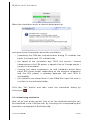
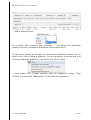
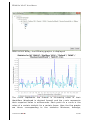
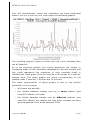
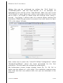
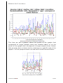
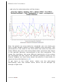
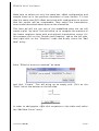
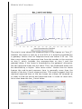
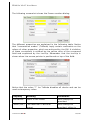
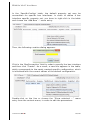
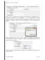
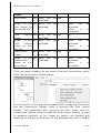
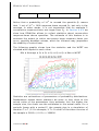
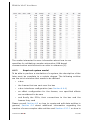
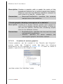
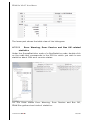
1
RTaW-Sim User Manual
Contact:
[email protected]
Product homepage at
http//www.realtimeatwork.com/software/rtaw-sim/
We help designers build truly safe and optimized systems
RTaW-Sim V1.4.7 User Manual
Date : 18/6/2014
Contents
1 Introduction.............................................................................................5
1.1 License of the software......................................................................5
1.2 Advanced features..............................................................................6
1.3 Installation...........................................................................................8
1.4 Support.................................................................................................8
1.5 New releases and updates.................................................................8
1.6 Changelog............................................................................................9
2 Glossary................................................................................................12
3 Quick-start............................................................................................13
3.1 Evaluating frame response times....................................................14
3.2 Visualizing statistics.........................................................................20
3.3 Analyzing the effects of clock drifts...............................................26
3.4 Analyzing the effects of event-triggered transmissions...............34
3.5 Analyzing the effects of transmission errors.................................41
3.6 Simulation with gateways................................................................48
4 Reference Manual.................................................................................58
4.1 Overview of the GUI..........................................................................59
4.2 Menus.................................................................................................60
4.2.1 File...................................................................................................60
4.2.1.1 Open / Import..............................................................................61
4.2.1.1.1 RTaW-Sim file...........................................................................62
4.2.1.1.2 NETCAR-Analyzer file..............................................................62
4.2.1.1.3 NETCARBENCH file..................................................................63
4.2.1.1.4 CSV import file........................................................................63
4.2.1.1.5 DBC file^..................................................................................66
4.2.1.1.6 FIBEX file^...............................................................................67
4.2.1.1.7 Autosar file^............................................................................67
4.2.1.2 Recent Files.................................................................................68
4.2.1.3 New..............................................................................................68
4.2.1.4 Merge / Import............................................................................68
4.2.1.4.1 Entire File.................................................................................68
4.2.1.4.2 Tx Error Models.......................................................................68
4.2.1.4.3 Selective^................................................................................69
4.2.1.4.4 From TraceInspector................................................................70
©2009-2014 RTaW
1/182
RT A W-S IM V1.4.7 U SER M ANUAL
4.2.1.5 Save.............................................................................................72
4.2.1.6 Save As........................................................................................72
4.2.1.7 Quit..............................................................................................72
4.2.2 Samples..........................................................................................72
4.2.3 Simulation......................................................................................73
4.2.4 Worst-Case.....................................................................................73
4.2.5 Optimization...................................................................................75
4.2.5.1 Rate Monotonic CAN Identifiers^.............................................76
4.2.5.2 Random Offsets..........................................................................76
4.2.5.3 SOA Offsets^..............................................................................77
4.2.6 What-If............................................................................................79
4.2.6.1 Scale load^.................................................................................79
4.2.6.2 Change identifier types to CAN2.0B^......................................81
4.2.6.3 Change frame types to CAN-FD................................................82
4.2.6.4 Group frames with same period (CAN-FD)...............................82
4.2.6.5 Scale payload (CAN-FD).............................................................83
4.2.7 Plot..................................................................................................83
4.2.8 Tools................................................................................................83
4.2.8.1 Anonymization of Names...........................................................84
4.2.8.2 Generation of Deadlines^.........................................................84
4.2.9 Help.................................................................................................85
4.3 Data editing.......................................................................................86
4.3.1 Creation..........................................................................................86
4.3.1.1 Creation from scratch................................................................86
4.3.1.2 Creation by duplication..............................................................89
4.3.2 Modification....................................................................................91
4.4 Definition of specific System Aspects.............................................92
4.4.1 Architecture....................................................................................92
4.4.1.1 Duplication of 'Architecture'.....................................................93
4.4.1.2 Creation 'from scratch'..............................................................93
4.4.1.3 Entity details...............................................................................99
4.4.1.4 Automatic layout......................................................................100
4.4.2 Frames..........................................................................................102
4.4.3 Frame gateways...........................................................................106
4.4.4 Bus interfaces configuration......................................................107
4.4.5 Transmission error occurrence models......................................112
4.4.6 Communication pattern..............................................................112
4.4.6.1 Segmented Transmission^......................................................113
4.4.6.2 Frame Dialogs^........................................................................118
4.5 Open or import an existing model................................................123
©2009-2014 RTaW
2/182
RT A W-S IM V1.4.7 U SER M ANUAL
4.6 Performing a simulation.................................................................123
4.6.1 Statistical concepts.....................................................................123
4.6.2 Required system model..............................................................127
4.6.3 Configuring and running a bus simulation................................128
4.6.4 Configuring a second run simulation^......................................133
4.6.5 Command line execution of a simulation^...............................134
4.7 Exploring performance evaluation results...................................138
4.7.1 Table view of frame response times..........................................138
4.7.2 Histogram view of statistics.......................................................140
4.7.3 Viewing the unfavorable scenario.............................................142
4.7.4 Frame statistics visualized as graphs.......................................143
4.7.4.1 Generation of frame response-time graphics.......................144
4.7.4.2 Creation of custom graphics...................................................145
4.7.4.3 Usage of periods and deadlines in frame response-time
graphics^...............................................................................................156
4.7.4.4 Creating graphics by copying.................................................157
4.7.5 Viewing of other statistics..........................................................159
4.7.5.1 Frame queue lengths...............................................................160
4.7.5.2 Error Warning, Error Passive and Bus Off related statistics .161
4.7.5.3 Busy period lengths.................................................................162
4.7.5.4 Segmented transmission response-times^...........................164
4.7.5.5 Frame dialog response-times^...............................................166
4.7.5.6 Second run statistics^.............................................................167
4.8 Exporting data.................................................................................170
4.8.1 Tabular data export.....................................................................170
4.8.2 Exporting graphics......................................................................171
4.8.3 The 'sim_results' folder...............................................................172
5 Simulation model...............................................................................173
5.1 Nominal CAN...................................................................................173
5.1.1 Instantiation of periodic Frames................................................173
5.1.2 Downward traversal of COM stack.............................................174
5.1.3 Arbitration and transmission......................................................176
5.1.4 Time drift of local clocks.............................................................177
5.1.5 Transmission delay statistics......................................................177
5.2 Gateways.........................................................................................177
5.2.1 Frame gateway............................................................................178
5.2.2 Transmission delay statistics......................................................178
5.3 Event-triggered transmissions of frames.....................................178
5.3.1 Overview.......................................................................................178
5.3.2 Simulation of event-triggered transmissions...........................179
©2009-2014 RTaW
3/182
RT A W-S IM V1.4.7 U SER M ANUAL
5.3.3 Transmission delay statistics......................................................179
5.4 Transmission errors.........................................................................179
5.4.1 Overview.......................................................................................179
5.4.2 Simulation of transmission errors..............................................180
5.4.3 Transmission delay statistics......................................................181
6 References..........................................................................................181
©2009-2014 RTaW
4/182
RT A W-S IM V1.4.7 U SER M ANUAL
1
Introduction
RTaW-Sim is a timing accurate simulator of Controller Area Networks
(CAN) that provides frame response time distributions and statistics
about the frame buffer usage at the microcontroller and
communication controller level. RTaW-Sim is able to simulate and
predict the performances of CAN 2.0A, CAN2.0B, ARINC825 and CAN
FD networks, possibly interconnected through gateways, with a very
accurate modeling of the communication stack and communication
controller. RTaW-Sim helps the designer compare the impact of
different design alternatives, choose the right communication stacks
(e.g., waiting queue policy) and communication controllers (e.g.,
number of buffers), and configure them. RTaW-Sim enables the
designer to also perform Simulation Based Fault Injection (SBFI), for
instance analyzing the effects of clock drifts or the impact of
transmission errors on transmission latencies.
Additional information about typical industrial use-cases of
RTaW-Sim, and how it relates to other temporal verification tools
such as RTaW-TraceInspector (trace analysis), can be found in
references [6] and [7] freely available from RTaW web site.
Section 3 offers six tutorials that allow to quickly get an insight into
the kind of analysis that the tool allows to perform. Section 4
provides a reference manual that describes all the functionalities
offered by RTaW-Sim. And finally, Section 5 explains the basic
functioning scheme of the simulation model underlying RTaW-Sim.
1.1 License of the software
RTaW-Sim is copyrighted by RTaW. In this License, "the Product"
means the software product "RTaW-Sim". The attached software
product is provided as is without warranty of any kind, either express
or implied, including, but not limited to, the implied warranties of
title, non-infringement, merchantability and fitness for a particular
purpose. No oral or written information or advice given by
REALTIME-AT-WORK, its agents or employees shall create a warranty
and user may not rely on such information or advice.
©2009-2014 RTaW
5/182
RT A W-S IM V1.4.7 U SER M ANUAL
- You may NOT resell, charge for, sub-license, rent, lease, loan or
distribute the Product without our prior written consent. We reserve
the right to withdraw any such consent (or part thereof) for any
reason and without notice and to demand that you immediately
cease any activity in respect of which permission is withdrawn.
Software developers SDK are available for licensing in 3rd party
software products.
- You may NOT repackage, translate, adapt, vary, modify, alter,
create derivative works based upon, or integrate any other computer
programs with, the Product in whole or in part.
- You may NOT use the Product to engage in or allow others to
engage in any illegal activity.
- You may NOT transfer or assign your rights or obligations under this
License to any person or authorize all or any part of the Product to
be copied on to another user's computer.
- You may NOT decompile, disassemble, reverse engineer or
otherwise attempt to discover the source code of the Product except
to the extent that you may be expressly permitted to reverse
engineer or decompile under applicable law.
REALTIME-AT-WORK and any third party software vendor or provider
shall have no liability to users or any customers of users for any
claim, loss or damage of any kind or nature whatsoever, arising out
of or in connection with (a) the deficiency or inadequacy of the
product for any purpose, whether or not known or disclosed to the
user, (b) the use or performance of the product, (c) any interruption
or loss of service or use of the product, or (d) any loss of business or
other consequential loss or damage whether or not resulting from
any of the foregoing.
In no event shall REALTIME-AT-WORK, or any third party software
vendor or provider, be liable to users or any customers of user for
any special, indirect, incidental or consequential damages, even if
the user has been advised of the possibility of such damages.
1.2 Advanced features
RTaW-Sim offers two categories of features:
•
basic features, available in all editions
•
advanced features, marked with a ^,
Professionnal edition
©2009-2014 RTaW
only available in the
6/182
RT A W-S IM V1.4.7 U SER M ANUAL
For
more
information,
[email protected].
please
contact
us
at
RTaW-Sim editions
Main Feature
Simulation of CAN buses
Starter
Pro
√
√
CAN2.0A
√
√
CAN2.0B
x
√
ARINC 825
x
√
CAN-FD
x
√
Gateways
√
√
Communication patterns
√
√
Event-driven transmissions
√
√
Frame dialogs (e.g. diagnostics)
x
√
Segmented transmissions
x
√
Transmission errors
√
√
Worst-case analysis of CAN buses
x
√
CAN20.A
x
√
CAN20.B
x
√
CAN-FD
x
√
Rare events statistics (→ Q6)
x
√
Optimizations
x
√
CAN identifiers
x
√
Transmission offsets
x
√
x
√
Scale Load
x
√
Migration to CAN2.0B
x
√
Migration to CAN-FD
x
√
x
√
Selective import
x
√
Import of typical tx error models
x
√
Duplication of entities
x
√
Curves with network perimeter
x
√
What-If analysis
Productivity features
©2009-2014 RTaW
7/182
RT A W-S IM V1.4.7 U SER M ANUAL
1.3 Installation
Installer based distributions are available for Windows and Linux.
More information and the download links for the free version are
available
at
the
following
address:
http://www.realtimeatwork.com/downloads/
1.4 Support
This help is integrated in the tool as html pages and as pdf
document:
If this help does not provide the answer you are looking for, or if you
encounter a problem, please refer to the FAQ or use the Helpdesk
forum:
http://www.realtimeatwork.com/forum/viewforum.php?f=6
If you need professional support or customized extensions, please
contact us at [email protected].
1.5 New releases and updates
To be informed about new releases and update, you should subscribe
to our eNewsletter here:
http://www.realtimeatwork.com/#subscribe
©2009-2014 RTaW
8/182
RT A W-S IM V1.4.7 U SER M ANUAL
1.6 Changelog
Version 1.4.7
Two options are provided for sorting frames in the unfavorable
scenario Gantt charts: by CAN id or grouped by sender first.
• Added close button to simulation dialog.
• Data dependency checks added on Frame attributes, to avoid
that analysis or simulation results get outdated with respect to
the input data on which they are based.
• Added “Role” column to CSV import, so that frames used in
frame dialogs and segmented transmissions can be imported;
not yet documented.
• Quicker access to statistics on frame dialog and segmented tx
delays added (see Section 4.7.5.4 and Section 4.7.5.5).
• SOA offset heuristic replaced by SOPA heuristic, which better
handles priorities (see Section 4.2.5.3).
• Possibility added to incrementally modify offset configurations
and to generate offsets only for a certain ECU (see Section
4.2.5.3).
• Round-trip import of RtaW-TraceInspector estimated parameters
(see Section 4.2.1.4.4).
• Worst-Case analysis extended to CAN-FD.
Version 1.4.6
•
“Enter” in a dialog is like clicking on the “Ok” button.
DBC file import: duplicated ENUM literal declarations
customer defined properties are now silently ignored.
Version 1.4.5
•
•
in
•
Estimation of remaining time displayed in simulation progress
bar.
•
Short-cut “Ctrl-C” added to tables for copying of selected lines
and “Ctrl-A” for selection of all lines.
•
Menu merge/import: added import of typical Tx Error models
with underlying probabilities laws, see Section 4.2.1.4.2.
Version 1.4.4
•
Improved topology layout in case of redundant buses.
©2009-2014 RTaW
9/182
RT A W-S IM V1.4.7 U SER M ANUAL
•
Correction of a problem that occurs when only “Intermediate
Statistics” are specified without an explicit “Length of
simulation” in the simulation dialog.
•
Correction of a problem that hindered the visualization of
unfavorable scenarios.
Version 1.4.3
•
Correction of a file corruption problem when ECUs or buses are
deleted.
Version 1.4.2
•
Reorganization of user menus.
•
Tabs in the tabbed panes can now be closed with the mouse
second button or the mouse wheel.
•
Tables can now be zoomed with “Ctrl+Mouse Wheel”.
•
Panels that display topologies now automatically gain focus so
that the zooming with “Ctrl+Mouse Wheel” does work without
having to first click on to the panel.
Version 1.4.1
•
Introduction of response times curves with “network” scope:
FrameNetworkStatCurve. This allows to summarize in a unique
curve all response times of a CAN communication architecture.
•
Combobox editor for frame payloads.
•
Correction of some problems and small improvements.
Version 1.4.0
•
Introduction of an Architecture entity that groups buses and
ECUs; this allows to describe, analyze and compare several
architectures in the same file.
•
Introduction of a graphical viewer and editor of the topology of
an Architecture.
•
Added, where appropriate, a “Create copy” menu entry in
context menus of tree nodes and table lines.
•
Added support for CAN-FD.
•
Added possibility to initialize the simulation configuration
dialog, according to an already performed simulation.
©2009-2014 RTaW
10/182
RT A W-S IM V1.4.7 U SER M ANUAL
•
Introduction of an option for load scaling, which allows to
preserve original frame identifiers.
Version 1.3.19
•
Simulation configuration dialogs keep now the parameters from
previous invocation (until the software is quit).
Version 1.3.18
•
Optional “receiver” column added to csv import format, see
Section 4.2.1.1.4.
•
For more comfort, the default CAN bus interface configuration
is now directly visible in the CANBusInterfacesConfig pane, see
Section 4.4.4.
•
Added a needed constraint on transmission offsets of frames:
offset < period.
• Java 7 is now required.
Version 1.3.17
•
“Glossary” section.
•
Shortcut “Ctrl+S” has been added for saving the current model
to its file.
•
Corrected problem that was hindering the simulation without
communication patterns.
Version 1.3.16
•
Moved Pdf of user manual and sample csv import files to the
“Samples” menu inside the tool.
•
Correction of rounding error in histogram buckets; has no effect
on values of quantiles.
•
Improvements of the frame panel, with respect to consistency
constraints.
•
New option for frame dialogs, that allows to decide when the
delay exactly starts: instantiation or transmission start of
request frame (see Section 4.4.6.2).
•
More and better default values for graph attributes.
•
Description of second run simulations added.
Version 1.3.15
©2009-2014 RTaW
11/182
RT A W-S IM V1.4.7 U SER M ANUAL
•
Gantt charts added for every bus concerned by an end-to-end
unfavorable scenario
•
Correction of hexadecimal CAN id in frame details pane.
Version 1.3.14
•
Completion of check for missing frame receivers
•
Automatic update of receivers column added.
•
Sample size to histogram added to data panes
Version 1.3.13
•
•
•
Time units have been added to response-time statistics in the
frames table of the bus details pane and the possibility to
export as CSV with or without units.
Frame error rate (FER) and bit error rate (BER) estimations
have been added to details pane of transmission error model,
see Section 4.4.5.
Clarified meaning of bus interface specific configurations, see
Section 4.4.4.
Main changes between Version 1.2.10 and Version 1.3.12
•
•
•
•
2
The main file format is changed to *.sim (= zipped *.xml to
reduce file size). The *.xml can still be opened and saved by
selecting the corresponding file filter.
Simulation of segmented transmission has been added, see
Section 4.4.6.1.
Simulation of frame dialogs has been added, see Section
4.4.6.2.
Flexible configuration of CAN bus interfaces, see Section 4.4.4.
Glossary
Term
Meaning
Frame instance
Since frames are usually sent in
some
recurrent
manner
(for
example periodically), several
instances of a frame are created
©2009-2014 RTaW
12/182
RT A W-S IM V1.4.7 U SER M ANUAL
at run-time, which usually differ
by their contents and exist at
different moments, but may also
exist concurrently, when the
transmission
of
a
previous
instance is still pending.
Frame instantiation time
Time where an instance of a
frame is ready (data has been
copied to the payload section)
and queued for participating in
the CAN arbitration. Once the
frame has been instantiated, its
contents
is
not
modified
anymore.
When the frame is actually
participating in the arbitration
and when its transmission exactly
starts, depends on the other
pending frame instances and the
scheduling policy of the CAN
communication stack.
Frame response time
Delay between the instantiation
time and the transmission end of
a frame instance.
Frame Deadline
Latency
constraint
on
response time of the frame.
3
the
Quick-start
The goal of this section is to allow you to get quickly an idea about
the kind of investigations RTaW-Sim allows to conduct on CAN based
communication Systems.
In Section 3.1 it is shown how to obtain statistics about the response
times of CAN frames (i.e., the time between a frame is ready to be
sent and the time it is received by all stations) and Section 3.2 is
dedicated to the exploration of the simulation results. In Section 3.3
we show the effects of clock-drifts, which are the main driver for the
©2009-2014 RTaW
13/182
RT A W-S IM V1.4.7 U SER M ANUAL
variability int the response-times of periodic frames. In Sections 3.4
and 3.5 we show how the effects of event-driven transmissions and
transmission errors can be analyzed for response time maxima of
CAN frames. And finally, in Section 3.6 the simulation with gateways
is illustrated.
3.1 Evaluating frame response times
This is the most basic feature of a CAN simulator and probably the
most useful because having a precise idea of the frame response
times on a CAN bus is diffi cult without a tool, as soon as there are
more than a few frames. It should be pointed out that if the
microcontroller clocks that drives the transmission are assumed to
not drift apart, provided periodic transmissions, then the response
times statistics converges very soon (basically two lcm of the frames
periods is enough) and it is not needed to simulate for a longer
duration. Of course, as soon the microcontroller clocks may have
drifts, as it occurs in practice, then it is less obvious to know how
long is enough but RTaW-Sim helps you in that regard with the
possibility to visualy check the convergence of statistics (see Section
4.7).
To begin with the tutorial, open the sample file that corresponds to
its start:
Double click on the node representing the bus called “CAN LS” (LS
stands for Low-Speed, this is a 125kbit/s network).
©2009-2014 RTaW
14/182
RT A W-S IM V1.4.7 U SER M ANUAL
… to get a detailed view of the bus:
Click on the “Architecture” panel to get an abstract view of the
topology:
©2009-2014 RTaW
15/182
RT A W-S IM V1.4.7 U SER M ANUAL
The window shows the name and the speed of the bus – in kbits/s, as
explained by the tool-tip of the label “Speed”. Furthermore, the
periodic bus load is displayed for the chosen bit-stuffi ng: “10%”
means that the bit-stuffed part of the frame is 10% longer than
nominal. With the worst-case option,
the increase is about 25%.
Below, the frames that are transmitted of the bus are displayed in a
table, with a column for each of the frame (related) properties.
Now we want to perform a simulation in order to obtain statistics on
frame response times, but first we need to save the sample file into
one of your personal folders (sample files are stored in a directory
that, depending on the OS, may not be writable by a regular user):
©2009-2014 RTaW
16/182
RT A W-S IM V1.4.7 U SER M ANUAL
Then open the simulation configuration dialog, for a CAN bus:
In the simulation configuration dialog that shows up, choose the
“Bus” 'CAN-LS' and the “Offset Configuration” 'DOA5' (DOA stands for
“Dissimilar Offset Assignment” which is a simple offset assignment
algorithm described in [2]). Furthermore, make sure to select
“NODRIFT” as “Drift Mode” (this will be explained in the next
section):
©2009-2014 RTaW
17/182
RT A W-S IM V1.4.7 U SER M ANUAL
Select “length & Sample Times” to specify the “intermediate Statistic
times”:
Then enter “Intermediate Statistics” times, i.e. time instance where
snapshots of the (evolving) response time statistics will be taken: 5s,
1m, 15m
©2009-2014 RTaW
18/182
RT A W-S IM V1.4.7 U SER M ANUAL
Enter the value 5 in the field before 's' and click “Add” ('s' stands for
second and 'm' for minute, see 2). Do the same for 1m and 15m. The
result should look like:
Now we are ready to start a simulation (the largest “Intermediate
Statistics” time being used as simulation length):
©2009-2014 RTaW
19/182
RT A W-S IM V1.4.7 U SER M ANUAL
When the simulation ends, a second dialog pops-up
and gives some information about the simulation:
•
simulating the CAN bus communication during 15 minutes has
taken 2 seconds and 117 milliseconds,
•
the speed of the simulation was 739.3 kilo events / second
(depending on the CPU power, a speed of up to 2 mega events /
second is achievable)
running the same experiment on real hardware would have
taken 425 times longer (depending on the network complexity
and the CPU power, a speedup between 100 and 1500 is
achievable),
the statistics are stored both in the RTaW-Sim input file and in
csv files in the indicated folder.
•
•
Click the “OK” button and then close the simulation dialog by
clicking on
.
3.2 Visualizing statistics
Now, let us look at the results. First of all, the obtained statistics can
be visualized in the CAN bus tab, by choosing the corresponding bus
simulation configuration“BusSimConfig” ...
©2009-2014 RTaW
20/182
RT A W-S IM V1.4.7 U SER M ANUAL
… and a sample time:
As a result, the columns Min, Average, … are filled (you probably
need to scroll or enlarge the window to see them well):
To get more easily an insight on how these statistics relate one to
each other, let us draw a graphic. For this purpose, one can use one
of the predefined graphics: pull-down the “Plot” menu ...
… and select the “Create graphic with all statistics” entry. Then
choose the statistics taken after 15 minutes of simulation:
©2009-2014 RTaW
21/182
RT A W-S IM V1.4.7 U SER M ANUAL
After a short delay, the following graphic is displayed:
The x-axis represents the frames in increasing order of their
identifiers (displayed in decimal format) and the y-axis represents
their response times in milliseconds. Each point on a curve is the
value of a certain statistic for a certain frame. Here the five graphs
are those corresponding to the statistics Minimum, Average,
©2009-2014 RTaW
22/182
RT A W-S IM V1.4.7 U SER M ANUAL
Maximum and two quantiles: (1-10 -2 )-quantile and (1-10 -3 )-quantile. A
(1-10 -n )-quantile is a threshold such that the probability that a
response-time of the frame is larger than that threshold, is lower
than 10 -n , see Section 4.6.1, for more details.
Some graphs may not be visible because, for a same frame, many
statistics may have the same value. Let us therefore hide the two
quantiles: click on the “Data” tab at left bottom.
This will bring up a table with the different graphs. Now, left-click on
the “Hidden” cell of the line that corresponds to the (1-10 -2 )-quantile
and mark the graph as hidden:
Do the same with the (1-10 -3 )-quantile. Then click in the “Graphic”
tab on the left bottom
in order to see the result:
©2009-2014 RTaW
23/182
RT A W-S IM V1.4.7 U SER M ANUAL
Now, all graphs are well visible, at least for most frames. For the
frames where only the minimum is visible, the average and
maximum have the same value as the minimum, meaning that the
response time of the frame is always the same – of course this is not
the typical behavior and it is due to the fact that station clock drifts,
variable bit-stuffi ng for the frames and transmission jitters are not
modeled in this example.
Before trying to understand this phenomenon, let us draw a graphic
that shows how statistics evolve with increasing sample size. For this
purpose, choose the corresponding entry from the “Plot” menu, for
the “Maximum” statistics:
©2009-2014 RTaW
24/182
RT A W-S IM V1.4.7 U SER M ANUAL
This will automatically select the simulation we have performed
before, since it is the only one, and create the following graphic:
The resulting graphic seems to show only one curve, because they
are all identical.
As in the previous graphic, the x-axis represents the frames in
increasing order of their identifiers (displayed in decimal format) and
the y-axis represents the maximum of their response times in
milliseconds. Each graph links the maxima of all frames for a specific
sample time. The three graphs are those corresponding to the
sample times 5 seconds, 1 minute and 15 minutes.
The exact superposition of these graphs is due to the perfect
periodicity of the system:
•
all frames are periodic,
•
the offsets between frames sent by a same station (aka
intra-ECU offsets) are fixed,
•
the offsets between frames sent by different stations (aka
inter-ECU offsets) are random but also fixed, because we have
ignored possible clock drifts between ECUs.
©2009-2014 RTaW
25/182
RT A W-S IM V1.4.7 U SER M ANUAL
The period of the system, also called hyper-period, is the least
common multiple of the frame periods (lcm for short), which is here
equal to 2 seconds.
It also explains the first graphic: the periodicity of the system allows
a reduced set of different possible response times for each frame
and in some cases only one value.
Notice however that a real CAN bus based communication system is
not strictly periodic because of clock-drifts, that makes the inter-ECU
offsets vary over time. To get an insight into the effects of
clock-drifts, the reader is invited to perform the tutorial on
clock-drifts in the next section.
3.3 Analyzing the eff ects of clock drifts
Let us introduce the effects of clock drifts. By “clock drifts” we
understand the fact that the clocks of the ECUs which drive the
periodic instantiations of the CAN frames do not exactly operate at
the same frequency. Due to production tolerances, the oscillators are
not exactly identical and their frequencies may also change over
time because of environmental factors such as the temperature.
If you have performed the previous part of the tutorial, just continue,
otherwise you can open the sample file that corresponds to the
beginning of the second tutorial:
Clock drifts can be modeled in sophisticated ways (they depend
essentially on the ambient temperature and the quality of the
quartz), but we will choose here a rather simple and widely
applicable one, based on fixed deviations of clock speeds (positive or
negative) with respect to a nominal speed. To avoid having to choose
each clock speed individually, RTaW-Sim allows to generate them
randomly in an user-defined interval. In the simulation configuration
©2009-2014 RTaW
26/182
RT A W-S IM V1.4.7 U SER M ANUAL
dialog, this can be configured by setting the “Drift Mode” to
“CONSTANT_DRIFT” and the “Drift Bound” to 1 for example. As
indicated by the tool-tip of the “Drift Bound” label, the unit of the
“Drift Bound” is ppm (parts per million) and means that the clocks
are at most 1 µs slower or faster than the nominal clock, every 1
second – 1µs being 1 millions part of a second. When starting the
simulation, RTaW-Sim generates a constant clock drift factor for each
ECU in the range 1±1ppm.
Now, make sure to select the “Inter-ECU Offset Configuration” called
“RandomComOffset0” which has been generated for the first
simulation. This will make the comparison meaningful.
We furthermore choose longer sample times (5s, 1h, 6h, 1d) to
better see the effects of clock drifts. The simulation requires more
time than the first one without drift, but you are informed of the
progress:
©2009-2014 RTaW
27/182
RT A W-S IM V1.4.7 U SER M ANUAL
The speed factor is this time much higher, because the GUI overhead
is much lower in proportion than in the first simulation. When the
simulation is finished, close the dialog as done before and turn back
to the 'CAN-LS' tab.
In order to visualize the generated constant clock-drift-factors,
double-click as shown below on the configuration called 'RandomDrift
+/- 1ppm' …
to open the details pane:
©2009-2014 RTaW
28/182
RT A W-S IM V1.4.7 U SER M ANUAL
As can be seen, some drifts are positive (i.e. the clock-drift factor is
above 1 and thus the clock faster than nominal) and some are
negative (i.e. the clock-drift factor is below 1 and clock slower than
nominal) and this within the specified bound of +/- 1 ppm.
Now a second “BusSimConfig” appears in the combo box in the Bus
panel.
Choosing it (and a sample time) makes the corresponding statistics
appear in the last columns of the table. And now let us plot a
convergence graphic for the statistic “Maximum” as before.
©2009-2014 RTaW
29/182
RT A W-S IM V1.4.7 U SER M ANUAL
Select the newly created “BusSimAnalysis” …
… and you will obtain the following:
©2009-2014 RTaW
30/182
RT A W-S IM V1.4.7 U SER M ANUAL
This time we see a graphic where the points of the graphs that
correspond to longer sample times are situated above or at the
points of the graphs that correspond to longer sample times. Notice
that you may have a closer look by zooming on a specific area of the
graphic. For this purpose select an area with the left mouse button:
©2009-2014 RTaW
31/182
RT A W-S IM V1.4.7 U SER M ANUAL
… and only the selected portion will be shown:
Now, the graphs can more easily be compared: one can clearly see
that a longer sample implies a higher response time maximum. This
phenomenon is the result of the clock drifts that make the inter-ECU
frame offsets vary over time and produce other scenarios than those
in the periodic behavior encountered in the first simulation. The
longer the simulation, the more different trajectories of the system
are simulated and the higher the maximal response times of the
frames. Readers can learn more about the effects of clock-drifts on
response-time distributions in [5].
To get back to the initial zoom, select use the auto-range
functionality from the context menu, which can be brought up
through a right-click:
©2009-2014 RTaW
32/182
RT A W-S IM V1.4.7 U SER M ANUAL
On the previous graphs, one can see, for example, that the maximal
response-time of the frame with decimal id = 669 is somewhat
higher than that of the frames with similar priority. Let us have a
look at the scenario that has lead to this high response time. For this
purpose, turn back to the details pane of bus “CAN LS” and locate
the line of “frame37”. Make sure that the BusSimulationConfig with
drift is selected and then right-click on the line in order to choose
“Show Unfavorable Scenario”:
As a result, the following Gantt chart is displayed:
©2009-2014 RTaW
33/182
RT A W-S IM V1.4.7 U SER M ANUAL
The waiting period (transparent, dotted rectangle) and the
transmission period (plain rectangle) of the “frame37” are underlined
in orange. It can be seen that “frame36” and “frame42”, which are
sent by the same “ECU1”, may be instantiated at the same time
than “frame37”. Furthermore, the clock-drifts lead to a situation
where 4 other ECUs (distinguished by colors) instantiate higher
priority frames before “frame37” is able to win the arbitration.
3.4 Analyzing the eff ects of event-triggered transmissions
After having investigated the effects of clock-drifts, let us study the
effects of even-triggered transmissions. If you have performed the
previous part of the tutorial, just continue, otherwise you can open
the sample file that corresponds to the beginning of the third
tutorial:
Event-triggered transmissions can occur with mixed frames ( i.e.,
frames with a periodic transmission pattern, but for which additional
instances can be transmitted between two periodic transmissions,
such as AUTOSAR mixed transmission mode) or pure event-triggered
frames. They have respectively the types “P+E” and “E”. In our
example we have both periodic and mixed frames, as can be seen by
looking at the “TxMode” column:
©2009-2014 RTaW
34/182
RT A W-S IM V1.4.7 U SER M ANUAL
Before doing a simulation, let us first have a look at the proposed
model for event-triggered transmissions; for this purpose click on the
“Specific Models” tab on left:
and then click on the “InFrequentEvents” node
in order to see the parameters of that model:
The model consists in a probability distribution for the delays (in
microseconds) between successive occurrences of the events that
©2009-2014 RTaW
35/182
RT A W-S IM V1.4.7 U SER M ANUAL
trigger transmissions. The corresponding attribute is called
“InterOccurrenceTime” and models the triggering events of all
frames with type P+E or E. In case of the “InFrequentEvents” model
such an event occurs every 100ms, on average.
When an event occurs, one frame is randomly chosen for
transmission, with equal probability among all mixed or
event-triggered frames, if the “FrameDistribution” attribute is not set
(see Section 5.3 for more details about the modeling of
event-triggered frame transmissions).
Let us now run a simulation:
Make sure to select not only the same bus, bit stuffi ng, offset
configuration and sample times as in the previous simulation (see
Section 3.1) but also the same inter-ECU offset and clock-drift
configuration, in order to ensure that the results will be comparable.
Then select the event occurrence model described above and run the
simulation.
This time we will not use one of the predefined plots but we will
create a plot “by hand” which will allow us to compare the maxima
©2009-2014 RTaW
36/182
RT A W-S IM V1.4.7 U SER M ANUAL
of the frame response times with and without transmission errors.
For this purpose click on the “Results and Graphics” tab on the left
side, then right-click on the “Graphics” node and finally chose the
“Add New” entry:
Enter “Effect of event triggered transmissions on maxima” as name
and click “Create”. This will bring up an empty plot. Click on the
“Data” tab at the bottom on the left side:
In order to add graphs, right-click anywhere in the table and select
the “Add New Curve” entry:
Enter “No events” as name and select “green” as color:
©2009-2014 RTaW
37/182
RT A W-S IM V1.4.7 U SER M ANUAL
Then left-click on the “BusSimulation” field and select the simulation
that corresponds to the case with drift but without event triggered
transmissions:
To finish, change the “Statistic” field to “Maximum”, the “Scope And
Kind of Times” field to “Bus Response Times”, the “Sample Time”
field to “1d” and click “Create”:
©2009-2014 RTaW
38/182
RT A W-S IM V1.4.7 U SER M ANUAL
Then create a second curve, but this time enter “Infrequent events”
as name and select “red” as color. As entry for the “BusSimulation”
field, select the simulation that corresponds to the infrequent events
case:
To finish change the default values of the “Statistic” and “Sample
Time” field as before and click “Create”:
©2009-2014 RTaW
39/182
RT A W-S IM V1.4.7 U SER M ANUAL
Then click on the “Graphic” tab on the left bottom ...
… to see the result:
As expected, the maxima of the response times increase; for some
frames, the difference reaches 5ms which, at 125 kbit/s, corresponds
to approximately 5 additional frames that preempt the considered
frame. There are two kinds of causes for the (high) response-time
increase:
•
if the frame is periodic then the occurrence of higher priority
event-triggered frame instances may delay the transmission
start until the beginning of a following burst of higher priority
periodic frame instances,
•
if the frame is mixed, then an event-triggered transmission
may occur during a burst of higher priority frames, which was
previously prevented by the transmission offsets for the time
triggered frame instances.
©2009-2014 RTaW
40/182
RT A W-S IM V1.4.7 U SER M ANUAL
Performing a similar simulation based on the “FrequentEvents”
model, and adding a similar graph to the previous plot gives the
following graph:
3.5 Analyzing the eff ects of transmission errors
After having investigated the effects of clock-drifts, let us study the
effects of transmission errors. If you have performed the previous
part of the tutorial, just continue, otherwise you can open the
sample file that corresponds to the beginning of the third tutorial:
Let us first have a look at the proposed model for transmission
errors; for this purpose click on the “Specific Models” tab on left
©2009-2014 RTaW
41/182
RT A W-S IM V1.4.7 U SER M ANUAL
and then double-click on the 'NonBurstyTransmissionErrorModel'
entry
which allows to see the details of the error model:
In RTaW-Sim, two types of transmission errors are identified: errors
that corrupt a single frame and burst errors that corrupt several
consecutive frames and translates into a period during which the bus
is not accessible (see Section 5.4 for more detail on that error
model). The “InterBurstCount” field shows the chosen distribution of
the “number of consecutive frames” between two successive
occurrences of transmission error bursts. We have chosen an
exponential distribution with parameter lambda=1/100, which means
that on average, there is a transmission error burst every hundred
transmitted frames. Notice that in our example there are
approximately 366 transmissions per second and thus, on average,
there is a transmission error burst every 273 milliseconds.
The “BurstLength” field shows the chosen distribution for the length
of a burst in “number of consecutive faulty frames”. The fields FER
(Frame error rate) and BER (Bit error rate) are computed by the tool
from the distributions.
To make the details of the chosen distribution visible, right-click on
the field ...
©2009-2014 RTaW
42/182
RT A W-S IM V1.4.7 U SER M ANUAL
… and chose the “Show details” entry of the pop-up menu, and then
click on the “Data” tab of the appearing pane:
Here, the distribution is actually non-random: always exactly 1
transmission error per burst.
When a transmission occurs, the simulator chooses randomly
(uniform distribution) one of the bits of the frame as detection time
of the error.
The “ErrorRecoverTimeInBits” field shows the chosen distribution of
the delay (in bits) until the error is eliminated and the bus is back to
normal functioning. When no distribution is specified, then the
simulator uses an uniform distribution over the set of possible
values: {14,15,...,27,28}.
Let us now run a simulation:
©2009-2014 RTaW
43/182
RT A W-S IM V1.4.7 U SER M ANUAL
Make sure to select not only the same bus, offset configuration and
sample times as in the previous simulation of (see Section 3.1) but
also the same inter-ECU offset and clock-drift configuration to ensure
that the results will be comparable. Then select the transmission
error model described above and run the simulation.
This time we will not use one of the predefined plots but we will
create a plot “by hand” that will allow us to compare the maxima of
the frame response times with and without transmission errors. For
this purpose click on the “Results and Graphics” tab on the left side,
then right-click on the “Graphics” node and finally chose the “Add
New” entry:
Enter “Effect of errors on maxima” as name
and click “Create”. This will bring up an empty plot. Click on the
“Data” tab at the bottom on the left side:
In order to add graphs, right-click anywhere in the table and select
the “Add New Curve” entry:
©2009-2014 RTaW
44/182
RT A W-S IM V1.4.7 U SER M ANUAL
Enter “No errors” as name and select “green” as color:
Then left-click on the “BusSimulation” field and select the simulation
that corresponds to the case with drift but without transmission
errors:
To finish, change the default “Statistic” to “Maximum”, the default
“Sample Time” to “1d” and click “Create”:
©2009-2014 RTaW
45/182
RT A W-S IM V1.4.7 U SER M ANUAL
Then create a second graph, but enter “Non-bursty errors” as name
and select “red” as color. As entry for the “BusSimulation” field,
select the simulation that corresponds to the case with non-bursty
transmission errors:
To finish change the default “Statistic” and “Sample Time” as before
and click “Create”:
Then click on the “Graphic” tab on the left bottom ...
©2009-2014 RTaW
46/182
RT A W-S IM V1.4.7 U SER M ANUAL
… to see the result:
As expected, the response-times are longer with transmission errors.
For some frames the difference reaches up to 5ms which corresponds
to approximately 5 frame length at 125kbit/s.
Notice that when a frame is corrupted by a transmission error, it is
sent again as soon as possible, but since higher priority frames
might have become ready since the start of the initial transmission,
the additional delay induced by the error can be much longer than
just the time between the transmission start and resorption of the
error. This effect is even stronger with bursty errors.
Performing
a
similar
simulation
based
on
the
“BurstyTransmissionErrorModel”, and adding a similar graph to the
previous plot gives the following graph:
©2009-2014 RTaW
47/182
RT A W-S IM V1.4.7 U SER M ANUAL
As expected, the bursts induce even longer response-times.
3.6 Simulation with gateways
In this section we will see how to configure a simulation with
gatewaying and how to visualize the results. To start with, let us
open an example with gateways:
The sample system contains a CAN bus at 250 kbit/s, a CAN bus at
500 kbit/s and one gateway that connects them, see below. The only
type of gateways that is currently supported is “frame gateway”,
©2009-2014 RTaW
48/182
RT A W-S IM V1.4.7 U SER M ANUAL
which serves to forward complete frames (and not signals) across
sub-networks (the exact networking terminology would be
“bridges”). If you expand the node “Ecu_1 ”, then the node
“Gateways” and finally double-click on the gateway “bus_1->bus_2”
you can see the mapping of the frames from the source network to
the target network. It can be seen that the forwarded frames have
the same names and identifiers on both buses, but this is not
necessary. The attribute “FrameDelayDistributions” allows to define
probability distributions for the gatewaying delay (in microseconds):
it is the delay between the reception of the frame by the gateway on
the source bus, and the time where the corresponding frame
instance is queued for being sent on the target bus. It should be
noticed that this delay does not include queuing and arbitration
delays. In our example we have chosen an uniform distribution
between 100 and 200 microseconds.
Let us now perform a simulation. For this purpose open the multi-bus
simulation configuration dialog:
©2009-2014 RTaW
49/182
RT A W-S IM V1.4.7 U SER M ANUAL
This dialog contains three sections:
This time, we will do a longer simulation to make sure that the
statistics converge. For this purpose left-click on the “Length &
Sample Times” label and enter the following sample times for the
statistics:
Now click on the “bus_1” node and then, in the right pane, check the
simulate box, choose the “SOA25” offset, “CONSTANTDRIFT” as “Drift
Mode” and finally 1000 as “Drift Bound”. We choose very high
clock-drifts rate in order to accelerate the convergence of the
statistics. More realistic values would be below 300ppm.
©2009-2014 RTaW
50/182
RT A W-S IM V1.4.7 U SER M ANUAL
Do the same for “bus_2”. If you click on “bus_1->bus_2” gateway
node, you will see that the unique “FrameDelayDistribution” is
already chosen:
©2009-2014 RTaW
51/182
RT A W-S IM V1.4.7 U SER M ANUAL
Now we can start the simulation which will take longer than in the
other tutorials, because not only we have chosen a longer simulation
time but also because the frames have shorter periods (ex. 10ms
instead of 100ms) and thus there are much more events to be
handled per second. As can be seen from the simulation report, on
longer simulations, the number of events treated per second is even
larger than in previous simulations.
In order to illustrate the convergence of statistics, let us draw the
convergence plot for the (1-10 -3 )-quantile; recall that for each frame,
the (1-10 -3 )-quantile is the threshold that is exceeded, on average,
by only 10 -3 = 1‰ transmissions of the frame. In order to draw the
convergence plot, choose the corresponding menu entry, as shown
below
and select the simulation result for bus_2:
©2009-2014 RTaW
52/182
RT A W-S IM V1.4.7 U SER M ANUAL
On the resulting graphic, we can see that with the exception of the
black curve, which corresponds to the very short sample time of 1
minute, all curves are quite close to each other.
In order to check this, click on the “Data” tab on the left bottom
©2009-2014 RTaW
53/182
RT A W-S IM V1.4.7 U SER M ANUAL
and hide the curves with the shorter sample time: 1m, 1h and 12h.
The resulting graph shows that between 22h and 24h, the statistics
have changed very little, meaning that they are very likely to be
close to the actual values.
Let us now create a graph that allows to study end-to-end
response-time, that is, response-times that include gateway delays,
©2009-2014 RTaW
54/182
RT A W-S IM V1.4.7 U SER M ANUAL
when the receiver is not located on the same bus as the sender. For
this purpose, left-click on the “Results and Graphics” tab in the lower
left corner …
… and then right-click on the “Graphics” node in order to create a
new graphic
called “Bus_2 end-2-end delays”. Then left-click on its “Data” tab
in order to add curves:
Entitle the first one “Bus_2 local delays”, with “Scope and Kind” set
to “Bus Response Time”
©2009-2014 RTaW
55/182
RT A W-S IM V1.4.7 U SER M ANUAL
and the second “Bus_2 end-2-end delays”, with “Scope and Kind” set
to “End-to-End Response Time”.
Notice that if you want to change the parameters of an already
created curve you can open the editing pane through the context
menu.
The result should be the following, after having clicked on the
“Graphic” tab in the lower-left corner of the pane:
©2009-2014 RTaW
56/182
RT A W-S IM V1.4.7 U SER M ANUAL
The black curve shows the response-time of the frames on “bus_2”,
whether the frame is sent by a local ECU or is actually forwarded by
a gateway. Notice that all response-times are below 3.25 ms. The
blue curve shows the response-time from the sender to the receiver
on bus_2, which includes the response-time on bus_1 and the
gateway delay, if the frame is forwarded by the gateway, otherwise,
the two response-times are the same. Thus, the forwarded frame can
be identified by a higher “blue curve value”. Notice that for these
frames the end-to-end response time is generally more than the
double of the bus_2 local response-time. This might suggest that the
maximal response-time of the two buses can simply be summed up
in order to find the end-to-end response-time. In order to check this,
let us also draw the bus_1 local times:
©2009-2014 RTaW
57/182
RT A W-S IM V1.4.7 U SER M ANUAL
This should result in the following graphic:
Notice that the frames which are forwarded from bus_1 to bus_2 are
those for which there are points on all three curves. As can be seen,
the end-to-end response-times (blue curve) are only a little higher
than the bus_1 local response-times and thus, the maximal
end-to-end response-times are generally not the sum of the local
maximal response-times (and the gateway delay). This means that
the maxima of each bus are unlikely to occur at the same time.
4
Reference Manual
This section provides a detailed description of all functionalities
offered by RTaW-Sim:
•
Section 4.1 gives an overview of the GUI
•
Section 4.2 describes all available menus
•
Section 4.3 tells how data editing works in general
•
Section 4.4 provides a detailed description of specific system
entities
•
Section 4.5 is about opening and import system descriptions
•
Section 4.6 explain how to perform a simulation
©2009-2014 RTaW
58/182
RT A W-S IM V1.4.7 U SER M ANUAL
•
Section 4.7 describes how to visualize simulation results
•
Section 4.8 explains how date can be exported
4.1 Overview of the GUI
Besides the classical menu bar at the top (see the figure below), the
user interface is subdivided into two parts. On the left, there are
expand-bars that show the different parts of the data under the form
of relation trees and, on the left in a tabbed folder, are displayed the
various panes that display details about the different data entities.
A containment tree consists of two kinds of nodes:
•
Data entity nodes, displayed in black
•
Relation category nodes, displayed in gray
A data entity node represents a data entity such as the description
of a CAN “bus” and is typically labeled by the name of the entity it
represents.
A relation category node represents a certain type of relation with
other data entities, like the set of frames on a bus.
©2009-2014 RTaW
59/182
RT A W-S IM V1.4.7 U SER M ANUAL
A double-click on a data entity node opens the corresponding
“details pane” as can be seen on the left side in the figure above for
the example of a frame.
The “Architecture” tree covers system defining entities like buses,
ECUs, frames and various configuration parameter definitions like
frame offset configurations.
The “Specific Models” tree covers data entities like models for
transmission errors, event-driven frames transmission and the
related probability laws.
The “Results and Graphics” tree covers the simulation results related
data entities such as response time statistics and graphics.
4.2 Menus
In this section are described all menus and their entries, available
from the menu at the top of the main window of the tool:
4.2.1
File
The entries of the “File” menu are described in the following
sections.
©2009-2014 RTaW
60/182
RT A W-S IM V1.4.7 U SER M ANUAL
4.2.1.1
Open / Import
In this section are described which kind of files the tool is able to
open or to import.
When the menu entry “Open / Import” is chosen, a file selection
dialog pops up. If you want to import data from files with a different
format than the (default) format of the tool, then, you need to select
the appropriate file name filter, as shown below for the case of “csv”
files:
The following table gives an overview of the file formats and the
ability to save back modifications.
File format
Extension
RTaW-Sim
*.sim, *.xml
Yes
Yes
Section
4.2.1.1.1
NETCAR-Analyze
r
*.xml
Yes
No
Section
4.2.1.1.2
NETCARBENCH
*.xml
Yes
No
Section
4.2.1.1.3
©2009-2014 RTaW
Open/Import Save More details
61/182
RT A W-S IM V1.4.7 U SER M ANUAL
RTaW CSV
*.csv
Yes
No
Section
4.2.1.1.4
DBC^
*.dbc
Yes
No
Section
4.2.1.1.5
FIBEX Xml^
*.xml
Yes
No
Section
4.2.1.1.6
AUTOSAR Xml^
*.xml
Yes
No
Section
4.2.1.1.7
4.2.1.1.1
RTaW-Sim file
RTaW-Sim files can be opened, imported and saved. Two variants are
supported:
•
zipped xml file, with the extension *.sim (the default format)
•
plain xml file, with the extension *.xml
Notice that the file selection dialog only shows files with the chosen
extension. Furthermore, if you select for example an xml file to be
opened or imported which is not a RTaW-Sim file, the tool will inform
you and ask if other known formats, such as the NETCAR-Analyzer
xml format, should be tried.
RTaW-Sim files can also be opened through the “Recent Files” entry
of the “File” menu. This sub-menu shows all previously opened files,
except the one that is currently opened.
4.2.1.1.2
NETCAR-Analyzer file
NETCAR-Analyzer is a software tool that allows to compute
worst-case response-times of
CAN frames and configure
communication parameters such as frame offset strategies or the
period of the middleware communication task when used. It is very
complementary to RTaW-Sim in the sense that it provides worst-case
results where RTaW-sim provides average or distribution quantiles on
the performance metrics. For more details, please consult the
following web-page:
http://www.realtimeatwork.com/software/netcar-analyzer
IMPORTANT NOTE: NETCAR-Analyzer has been discontinued as a
stand-alone product, it is now exclusively distributed as a RTaW
plugin that is available in the Professional edition.
©2009-2014 RTaW
62/182
RT A W-S IM V1.4.7 U SER M ANUAL
RTaW-Sim is able to read legacy NETCAR-Analyzer xml files (choose
“NETCAR-Analyzer xml file” format in the import windows, see
Section 4.5) and to import the contained CAN bus, ECUs, frames,
offset configurations and the computed worst-case response-times;
the later can then be compared with the response times obtained by
simulation (see ref [4] for a study showing the differences one can
expect between simulation and analysis results).
IMPORTANT NOTE: until the version 1.4.1 of NETCAR-Analyzer, the
worst-case response-times must have been computed in the order of
appearance of the
corresponding offsets, otherwise their
correspondence could be incorrect in RTaW-Sim.
4.2.1.1.3
NETCARBENCH file
NETCARBENCH is a GPL-licensed software that generates automotive
message sets according to a set of user-defined parameters.
NETCARBENCH allows to generate realistic sets of messages that can
be used for comparing configuration algorithms or making design
choices - it is especially useful early in the design cycle when the
real message sets are not yet available, for the embedded system
architecture design or for assessing the maximum load that can be
achieved on a certain bus. Another interest of NETCARBENCH is that
the message sets it generates can be communicated, overcoming
the confidentiality requirement one has with real sets of messages.
RTaW-Sim can import NETCARBENCH generated files (choose
“NETCAR-Analyzer xml file” format in the import windows, since
NETCARBENCH format is a subset of NETCAR-Analyzer one). In a first
step, you may for instance test this possibility using the example
configuration files (e.g., automotive powertrain and body networks)
available on the NETCARBENCH home page.
4.2.1.1.4
CSV import file
As its name says, this kind of file contains “Character Separated
Values” (CSV) but it is easier to understand as textual data under a
tabular form, as shown in Table 1.
The current format (1.2) allows to describe (and import) an
architecture consisting in one or several CAN buses, connected by
©2009-2014 RTaW
63/182
RT A W-S IM V1.4.7 U SER M ANUAL
frame gateways, with periodic, event-triggered or mixed frames and
one or several transmission offsets.
Table 1: Sample CSV import file shown as table
Table 1 shows the contents of the sample file “Sample Csv Import
File”, which is accessible through the “Samples” menu:
©2009-2014 RTaW
64/182
RT A W-S IM V1.4.7 U SER M ANUAL
Notice that these are Excel files which need to be saved as CSV file
(with ; as separator) before the actual import, but we have chosen
the Excel format so that “sections” and keywords may be highlighted
and the overall structure can be understood more easily.
The CSV format foresees two types of sections:
•
required “Bus” sections, for the description of a bus and the
frames
•
optional “Bridge”
gateways
sections
for
the
description
of
frame
The meaning of the different parameters is as follows:
©2009-2014 RTaW
65/182
RT A W-S IM V1.4.7 U SER M ANUAL
4.2.1.1.5
DBC file^
DBC is a proprietary VECTOR Informatik Gmbh file format that is very
widely used for describing CAN based communication systems.
RTaW-Sim/Professional edition includes a DBC file importer. You need
to select the “Vector DBC file” filter in the file selection dialog (see
Section 4.5) in order to import *.dbc files. Then, the following dialog
is shown in order to provide additional information needed by the
converter:
©2009-2014 RTaW
66/182
RT A W-S IM V1.4.7 U SER M ANUAL
First of all, the bus speed needs to be provided because it is not
contained in the DBC file.
Second, there are no standard attribute names for frame periods and
frame transmission offsets. The dialog proposes by default the
custom attribute names that are used by the Vector Tool Chain. You
can edit the fields and change the names according to your needs.
4.2.1.1.6
FIBEX file^
FIBEX (Field Bus Exchange Format) is an XML format used to describe
message-oriented communications systems. It is an ASAM standard
that now supports FlexRay™, CAN, MOST and LIN networks and that
became the de-facto standard for FlexRay tool support.
RTaW can provide a converter allowing to import FIBEX files into
RTaW-Sim (OEM specific extensions can be supported). Contact the
support if you need this functionality.
4.2.1.1.7
Autosar file^
Autosar™ is an ongoing automotive industry initiative aimed at
standardizing electronic architectures and their development
process. The “system template” XML description contains the
description of the communication systems.
RTaW can provide a converter allowing to import AUTOSAR XML files
into RTaW-Sim. Contact the support if you need this functionality.
©2009-2014 RTaW
67/182
RT A W-S IM V1.4.7 U SER M ANUAL
4.2.1.2
Recent Files
The “Recent Files” menu entry, provides a quick-list of recently
opened files:
Notice that the currently opened file does not appear in the list.
4.2.1.3
New
Allows creating a new empty and unsaved model. If at the time of
invocation, the currently opened model has unsaved changes, then
the tool asks first if these should be saved.
4.2.1.4
Merge / Import
In the following sub-sections we describe the different possibilities to
merge data from other model files into the currently opened model.
4.2.1.4.1
Entire File
This functionality allows to import all data entities from a specified
file into the current model. The imported entities are put side by
side with the existing ones.
4.2.1.4.2
Tx Error Models
This functionality allows to import, into the current model, some
typical transmission error models, together with the underlying
probability laws.
The imported entities are then shown in the “Specific Models”
section:
©2009-2014 RTaW
68/182
RT A W-S IM V1.4.7 U SER M ANUAL
4.2.1.4.3
Selective^
This functionality allows to import parameter sets with automatic
mapping of related entities. Parameter sets that may be imported
are:
•
CANBusInterfaceConfig
•
OffsetConfig
•
ComOffsetConfig
•
ClockDriftConfig
•
OccurrenceModel (of communication patterns)
•
ProbabilityLaw
•
EventOccurrenceModel
•
TxErrorModel
Once you have selected the model file, the following selection dialog
appears:
©2009-2014 RTaW
69/182
RT A W-S IM V1.4.7 U SER M ANUAL
Notice that with “Ctrl + left mouse button” you can select several
individual parameter sets for import.
It allows for example to import an OffsetConfig from an other model
file, that contains the description of the same or similar
communication configuration. The mapping of the frames concerned
by the offsets is established based on the name of the frame, the
name of the bus to which the frame belongs and the name of
architectures to which the bus belongs. If a correspondence can not
be established automatically then the tool asks the user to identify
explicitly the corresponding entity. The later may for example
happen if an entity has been renamed.
4.2.1.4.4
From TraceInspector
This functionality allows to import parameter sets that have been
estimated from a communication trace with RTaW-TraceInspector. The
parameter sets include
•
clock-drifts,
•
transmission offsets,
•
inter-occurrence time distribution of event-driven transmissions
•
inter-occurrence count
transmission errors
and
burst
size
distribution
of
In order to do so, make first sure to have opened the RTaW-Sim file
into which the parameters shall be imported. Then selected the
©2009-2014 RTaW
70/182
RT A W-S IM V1.4.7 U SER M ANUAL
menu entry File->Merge/Import->From TraceInspector. You will be
asked to select the RTaW-TraceInspector file (*.insp) form which to
import the parameter sets. Then the specified file will be parsed and
you will be invited to select the “trace inspection” containing the
parameter sets to import:
Then you will be asked to specify the corresponding bus in RTaW-Sim
where the parameters sets shall be copied to:
The matching of frames and ECUs between RTaW-TraceInspector and
RTaW-Sim is based on their names. If no corresponding entity can be
found by name, then the tool asks you to explicitly select one.
Finally, the import is executed for all parameter sets that are
available in the selected trace inspection.
©2009-2014 RTaW
71/182
RT A W-S IM V1.4.7 U SER M ANUAL
4.2.1.5
Save
Saves the currently opened model to its file. If the model has never
been saved to a file then a dialog allows to specify a file (name). The
key combination Ctrl+s is a short-cut for this action.
4.2.1.6
Save As
Allows to save the model into a file with a possibly different name.
4.2.1.7
Quit
Shuts down the tool. The key combination Ctrl+q is a short-cut for
this action.
If at the time of invocation, the currently opened model has unsaved
changes, then the tool asks first if these should be saved.
4.2.2
Samples
This menu allows to open different sample files:
The “Case Studies” are those of Reference[4]:
The Tutorials are used in Section 3:
The “Csv Import” samples can be used as basis for CSV import files,
see Section 4.2.1.1.4:
©2009-2014 RTaW
72/182
RT A W-S IM V1.4.7 U SER M ANUAL
4.2.3
Simulation
This menu contains several entries for configuring and starting
simulations:
The “Simulation” entry allows to configure a simulation from
scratch, see Section 4.6 for more details. It contains a sub-menu with
an entry for every existing “Architecture”:
Selecting for example the
configuration dialog for “S0”.
entry
“S0”
opens
the
simulation
The “Initialize from existing”^ menu entry allows to initialize the
simulation configuration from existing simulation results. This allows
to easily and quickly perform a simulation with few configuration
changes.
The “Second Run Simulation”^ menu entry allows to perform a
second run simulation for statistical purpose, see Section 4.6.4 for
more details.
4.2.4
Worst-Case
This menu contains an entry for computing worst-case response time
bounds:
©2009-2014 RTaW
73/182
RT A W-S IM V1.4.7 U SER M ANUAL
As for the simulation, it contains a sub-menu with an entry for every
existing architecture. Selecting for example “S1” opens the
configuration dialog for the architecture “S1”:
For each bus you have to select the “bit stuffi ng” and the
transmission offsets to be used in the computation.
For each gateway, you have to select a “Frame delay distribution”.
The worst-case analysis will use the maximum of this distribution.
When you have clicked on “Yes” to start the computation, the
following progress-bar appears:
©2009-2014 RTaW
74/182
RT A W-S IM V1.4.7 U SER M ANUAL
Notice:
•
The worst-case analysis assumes that communication stacks
behave perfectly, i.e. that no priority inversions occurs. This is
different
from
simulation
where
different
non
ideal
communication stack behaviors may be taken into account, see
Sections 4.4.4 and 4.6.3.
•
if no gateway is present, then a single computation step is
suffi cient; furthermore, the results are worst-case response
times that may effectively occur.
•
if gateways are present, then thenumber of iterative
computation steps that is required cannot be foreseen
beforehand; furthermore the results of the computation are
upper bound on the worst-case response times.
When the computation is done, a SystemEvaluation entity appears
under the “Evaluations” node in the results and graphics section:
On how to effi ciently visualize the computed
response-time (bounds) see Sections 4.7.1 and 4.7.4.2.
4.2.5
worst-case
Optimization
The optimization menu offers functionalities
optimization of offsets and priorities:
©2009-2014 RTaW
related
to
the
75/182
RT A W-S IM V1.4.7 U SER M ANUAL
4.2.5.1
Rate Monotonic CAN Identifiers^
This functionality allows to modify CAN identifiers so that a frame
with a smaller period has a smaller identifier and thus a higher
priority, this is called the Rate Monotonic priority assignment
scheme. Though Rate Monotonic is not necessarily the best policy
with regard to meeting time constraints, in practice it provides a
sound basis to start with.
Notice that since the functionality modifies the priorities, it might be
useful to apply it on a copy of a reference Architecture (see Section
4.3.1.2 for how to create such a copy). This way you will be able to
analyze and compare the reference architecture with the one with
rate monotonic CAN identifiers.
When the menu entry is selected, the following menu appears:
If no specific bus is selected, than all buses of the architecture are
modified, otherwise only the specified bus is touched.
4.2.5.2
Random Offsets
This functionality allows to generate random transmission offsets for
a specified bus:
The granularity must be a common divider of the periods of all
frames and all offsets will be a multiple of the granularity. The
smaller the granularity, the smaller will be the resulting response
times, but more sophisticated algorithms like SOA, produce much
better offsets that lead to much smaller response-times.
©2009-2014 RTaW
76/182
RT A W-S IM V1.4.7 U SER M ANUAL
Randomly generated offsets are in general much less effective than
optimized offsets or offset generated by a heuristic, but they are
useful for benchmarking offset configurations and gaining a good
insight into how useful it is to implement offsets.
4.2.5.3
SOA Offsets^
This functionality allows to generate very good transmission offsets
with the help of RTaW's SOPA heuristic:
First select an “Architecture” and then the “Bus” for which the
transmission offsets should be generated. The granularity must be a
common divider of the periods of all frames (the combo box only
contains these kinds of values) and all offsets will be a multiple of
the granularity.
The parameter “Ecu” allows to restrict the generation to a single
Ecu.
The parameter “Basis” allows to specify an existing transmission
offset configuration that will be used as basis. If “Modify Basis” is
checked, then the offset configuration specified as “Basis” will be
modified, otherwise a copy of the “Basis” will be created and
modified.
Application notes: In order to generate a partial offset
configuration and/or an offset configuration with different
granularities for certain ECUs, you can start with a “zero” offset
configuration, which you then modify progressively:
1) You may create for example a new configuration in the exploration
tree
©2009-2014 RTaW
77/182
RT A W-S IM V1.4.7 U SER M ANUAL
with a default offset (0, in the example below):
Or you may start to generate an offset configuration with identical
granularity for all ECUs, with the help of the “Random Offsets” or
“SOPA Offsets” algorithm in order to obtain a basis to modify in the
sequel.
2) Then, use again the the “SOPA Offsets” dialog in order to
particularize the transmission offset for some ECUs:
©2009-2014 RTaW
78/182
RT A W-S IM V1.4.7 U SER M ANUAL
Recall that if you check “Modify Basis”, then the offset configuration
will be modified each time, but often it is also interesting to keep the
intermediate configurations, in order to analyses which step
produced the highest impact.
4.2.6
What-If
This menu provides several functionalities that allow to modify
communication architectures in order to analyse the effects of
certain evolutions:
Consider modifying a copy of the original architecture (see Section
4.3.1.2 for how to create such a copy): this way you will be able to
analyze and compare the modified communication architecture with
the original one.
4.2.6.1
Scale load^
This function allows to increase the periodic bus load of an existing
bus, by duplicating subset of frames, while not changing the number
of ECUs connected to the bus.
Consider applying this functionality to a copy of the original
architecture (see Section 4.3.1.2 for how to create such a copy). This
way you will be able to analyze and compare the higher loaded
communication architecture with the original one.
When you select the menu entry, the following dialog appears:
©2009-2014 RTaW
79/182
RT A W-S IM V1.4.7 U SER M ANUAL
The configuration parameters have the following meanings:
Architecture: communication architecture where bus loads are
scaled
• Bus: the bus where the resulting load should reach the
specified “Target Load”
• Bit stuffi ng: the bit-stuffi ng load to consider when computing
the resulting periodic bus load
• Target Load: the periodic bus load that should be achieved on
the target bus
• Keep identifiers:
• if not checked, then each frame copy will have an
identifier one unit smaller than the original frame (i.e. a
higher priority than the original frame) and to achieve
this, all frame identifiers are redefined
• if checked, then the algorithm does not modify any
existing identifier, and tries to assign an identifier one
unit smaller than the original frame, but if this is not
possible, because this chosen identifier is already used,
then the first free higher identifier is chosen.
Based on these parameters, the algorithms applies a homothetic
increase of the frame sets, i.e. it rescales the frame set while
keeping its characteristics similar to the original. For example, the
proportion of frames with a period of 100ms will remain the same
after rescaling. If the original set contains 6 frames with period
100ms, and if the load is increased by 50%, then the generated set
will contain 9 frames with a period of 100ms.
•
The algorithm proceeds as follows:
©2009-2014 RTaW
80/182
RT A W-S IM V1.4.7 U SER M ANUAL
1. On the specified bus: selection of a subset of frames, uniformly
distributed over the existing range of identifiers; the number
of selected frames is proportional to the load increase.
2. Bridging is treated as follows: if a duplicated frame is the
retransmission of a frame from some other bus or is itself
retransmitted on some other bus, then also all preceding or
successive frames are duplicated. In other words the whole
chain of frames is duplicated.
3. On all other buses: duplication of a proportional part of all the
frames that are neither retransmissions nor themselves
retransmitted on some other bus.
Notice:
•
if a system consists of two buses with for example the
respective loads 40% and 30% and if the target load on the
first bus is 60% = 1.5 * 40%, then resulting load on the second
bus will be 45% = 1.5 * 30%.
4.2.6.2
Change identifier types to CAN2.0B^
This function allows to change all CAN2.0A identifiers of a bus or of
all buses of an architecture into CAN2.0B identifiers. This is useful
for
transforming CAN2.0A configuration files into CAN2.0B
configuration files.
• studying the effects of using long identifiers on the global
network load.
When you select this menu entry then the following dialog is
displayed:
•
First you have to select an architecture. If you do not select a bus,
then the change is applied to all buses of the architecture, otherwise
only to the selected bus.
Notice:
•
The extended part of the migrated identifiers is set to 0.
©2009-2014 RTaW
81/182
RT A W-S IM V1.4.7 U SER M ANUAL
4.2.6.3
Change frame types to CAN-FD
This function allows to change the type of all frames of a bus or of all
buses of an architecture to CAN-FD. This is useful for
transforming CAN2.0A/B configuration files into CAN-FD
configuration files.
• studying the effects of a migration to CAN-FD on bus loads and
frame response times.
When you select this menu entry then the following dialog is
displayed:
•
First you have to select an architecture. If you do not select a bus,
then the change is applied to all buses of the architecture, otherwise
only to the selected bus.
Notice:
•
•
the CAN-FD speed property must first be set for the bus(es) to
migrate
this functionality does not increase the payload of the frames
4.2.6.4
Group frames with same period (CAN-FD)
This function allows to exploit the higher payload of CAN-FD frames
by grouping frames that
1. are sent by the same ECU
2. have the same period
3. either
• none is forwarded by a bridge
• all are also forwarded by a bridge
When you select this menu entry, the following dialog appears:
©2009-2014 RTaW
82/182
RT A W-S IM V1.4.7 U SER M ANUAL
You have to select an architecture.
Notice:
•
•
all frames of the selected architecture must have the type
CAN-FD
the name of the grouped frames is a concatenation of the
names of the original frames
4.2.6.5
Scale payload (CAN-FD)
This function allows to increase the frame payloads, by multiplying
them by the factor “CAN-FD Speed / Standard CAN speed”. The
rationale of this function is to evaluate the extent to which the
additional bandwidth offered by CAN-FD can actually be taken
advantage of to transmit larger data payloads. Some good insight
into this question can be obtained with the response times of the
CAN-FD network with the larger data payload.
When you select this menu entry, the following dialog appears:
You have to select an architecture.
Notice:
•
•
all frames of the selected architecture must have the type
CAN-FD
the functions fails, if due to the scaling a payload would be
higher than 64 bytes.
4.2.7
Plot
See Section 4.7.4.1.
4.2.8
Tools
Several useful tools are available in the menu “Tools”:
©2009-2014 RTaW
83/182
RT A W-S IM V1.4.7 U SER M ANUAL
4.2.8.1
Anonymization of Names
This function changes potentially confidential names into anonymous
names of the form “Type_N”. For example, frames will be renamed to
Frame_1, Frame_2, etc. This function is useful when a configuration
file has to be transmitted outside a company/institution and the
names of the frames and nodes cannot be communicated for
confidentiality reasons. Potentially confidential names are those of
•
Architectures
•
Buses
•
Frames
•
ECUs
•
Communication Patterns
4.2.8.2
Generation of Deadlines^
This function allows to generate deadlines as percentage of frame
periods. This is useful when no individual frame deadlines are known,
but only some general rule about the latency constraints on the
frame response times.
There are two variants of the functions:
•
•
generation of frame deadlines, that applies to the transmission
on the specified bus
generation of timing chain deadlines, that applies to end-to-end
transmission through gateways, from the source ECU until the
reception by ECUs on the specified bus.
©2009-2014 RTaW
84/182
RT A W-S IM V1.4.7 U SER M ANUAL
Both kinds of deadlines can be visualized in the bus pane in the
“Deadlines” column, by selecting “Bus Response Times” or
“End-to-End Response Times”. Notice that for a frame that is not
sent by a gateway, the local deadline is always displayed, whatever
scope is chosen.
4.2.9
Help
The user manual is available in two formats
•
HTML, accessible through the help menu: “? → Help (Html)”
•
PDF, accessible through the help menu: “? → Help (Pdf)”
“Help WCRT” is the help for the Worst Case Analysis Plug-in available
in the Professional edition of RTaW-Sim.
©2009-2014 RTaW
85/182
RT A W-S IM V1.4.7 U SER M ANUAL
Furthermore, tool tips on property labels often provide a short
definition. To make them visible, simply position the mouse pointer
over the label:
4.3 Data editing
In this section is described how new data entities such as buses,
frames, graphics, can be created (Section 4.3.1) or modified (Section
4.3.2).
4.3.1
Creation
In this section we show how data entities can be created “from
scratch”, see Section 4.3.1.1 or by duplicating an existing one, see
Section 4.3.1.2.
4.3.1.1
Creation from scratch
The creation of a new data entity can be initiated through the
context menu of the relation category nodes (those with gray labels)
in the relation trees.
To create a new bus, right-click on the “Buses” node and select the
“Add New” menu item.
©2009-2014 RTaW
86/182
RT A W-S IM V1.4.7 U SER M ANUAL
This brings-up a dialog, where some required parameters must be
set, such as the “ShortName” and the speed.
If a value is wrong or missing, then the field is displayed in yellow.
The tool-tip of the field describes then the problem.
If you click on the “Create” Button before all errors are corrected and
missing values are provided, then the tool pops up a dialog with an
error message like this one:
Notice that the tool-tips of the labels might provide some information
about the required value, such as the time unit (kbits/s) in the
example of the bus speed.
If you are not able to provide (correct) values you can abort the
creation by clicking on the “Cancel” button.
After having successfully clicked on the “Create” button, the
corresponding details pane opens in the tabbed folder on the left of
the user interface, as shown below for the bus.
©2009-2014 RTaW
87/182
RT A W-S IM V1.4.7 U SER M ANUAL
The creation of a new data entity can also be initiated through the
context menu of the tables that can be found in the details panes.
Let us take the example of frames: in the bus details pane,
right-click anywhere in the “Frames” table and select the “Add New
Frame” entry...
… to bring up the frame creation dialog:
Remember, that the same frame creation dialog can also be obtained
through the context menu of the relation node “Frames” under the
bus entity node:
©2009-2014 RTaW
88/182
RT A W-S IM V1.4.7 U SER M ANUAL
As soon as you have successfully created a new frame, it appears in
the table
and under the relation category node “Frames”.
4.3.1.2
Creation by duplication
Many (composed) data entities (but not all) can be duplicated. For
instance, it is possible to duplicate:
•
Architecture
•
Frame
•
CANBusInterfaceConfig
•
OffsetConfig
•
ComOffsetConfig
•
ClockDriftConfig
•
OccurrenceModel (of communication patterns)
•
ProbabilityLaw
•
EventOccurrenceModel
•
TxErrorModel
•
Graphic
•
Curve
©2009-2014 RTaW
89/182
RT A W-S IM V1.4.7 U SER M ANUAL
When a data entity consists of sub-entities (sub-nodes in the
exploration tree), then also all sub-entities are duplicated; for
example, if an Architecture entity is duplicated, then also all its
ECUs, Buses, Frames, OffsetConfigs, etc, are duplicated.
If an entity can be duplicated then a “Create Copy” menu entry is
available in its context-menu in the exploration tree:
and in the table view:
Before actually creating the copy, a dialog allows to set the name of
the duplicata, which you should change to be able to distinguish the
copy from the original:
©2009-2014 RTaW
90/182
RT A W-S IM V1.4.7 U SER M ANUAL
4.3.2
Modification
Existing data entities can be modified in their details pane on the
right-hand side of the user interface.
Remember that the details pane of a data entity can be accessed by
double-clicking on the corresponding node in the relation tree under
the expand-bars on the left.
The details panes can also be accessed through the context menu in
a table (right-click on a line). Below the example of the “Frames”
property in a bus details pane:
And finally, they can also be accessed through the context menu of a
reference field in a details pane (right-click on the field), as shown
below for the BurstLength reference in the details pane
of a
TransmissionErrorModel:
Parameters that are displayed in a text field can be edited as
expected (simple text editor). If an input is illegal (letter when a
number is expected), then an error message pops up to inform the
user about the problem. If an entered value is invalid (negative
number when a positive number is required) or required but deleted,
then the back-ground of the text field changes to yellow and the
tool-tip provides more information about the error.
©2009-2014 RTaW
91/182
RT A W-S IM V1.4.7 U SER M ANUAL
References to other data entities may be either displayed in a
combo-box …
… or in a text field:
In the later case they can be changed by clicking on the field, which
brings up a dialog that allows to select a (new) reference.
4.4 Defi nition of specifi c System Aspects
In this section we describe how to define specific system aspects.
4.4.1
Architecture
An “Architecture” entity groups all information related to the
description of a communication architecture. An architecture is made
up of buses, ECUs and communication patterns, which consists of
frames and the communication stack related configuration
parameter sets:
©2009-2014 RTaW
92/182
RT A W-S IM V1.4.7 U SER M ANUAL
4.4.1.1
Duplication of 'Architecture'
Architecture entities may be duplicated, see also Section 4.3.1.2:
All contained sub-entities such as buses, ECUs, communication
patterns, frames, communication stack related configuration
parameter sets, etc. are also duplicated.
Thus, copies of architectures are independent and can be modified
separately. This is useful for analyzing and comparing architectural
alternatives.
4.4.1.2
Creation 'from scratch'
Let us build a system from scratch: right-click on the “Architecture”
node in the exploration tree
©2009-2014 RTaW
93/182
RT A W-S IM V1.4.7 U SER M ANUAL
and select “Add new”:
In the creation dialog, provide a name for the new architecture and
select “Create”:
A new panel “arch1” is created.
There are two alternatives for creating new buses and Ecus. Either
through a right-click on the “Buses” or “Ecus” node in the
exploration tree
or through the context menu of the architecture panel on the right,
by selecting the “Add new bus” entry:
©2009-2014 RTaW
94/182
RT A W-S IM V1.4.7 U SER M ANUAL
When a new bus is created then the following creation dialog
appears, where a name and a transmission speed must be provided:
When a new ECU is created then the following creation dialog
appears, where a name must be provided:
Once the minimal required properties are provided and “Create” has
been clicked, the rest depends on how the creation has be initiated.
If the creation has been initiated from the exploration tree on
the left, then the details pane of the object is opened on the right,
as for example for a bus:
©2009-2014 RTaW
95/182
RT A W-S IM V1.4.7 U SER M ANUAL
If the creation has been initiated form architecture graph pane,
then the node corresponding to the newly created entity appears at
the point where the context-menu has been invoked:
©2009-2014 RTaW
96/182
RT A W-S IM V1.4.7 U SER M ANUAL
An ECU can also be connected to bus in two ways, either in the
exploration tree or in the architecture graph panel.
For the first alternative, right-click on the “BusConnections” node
under Ecu1 in the exploration tree and select “Add New”:
This brings up the following dialog:
The only possible choice “bus1” is selected by default; click on
“Create” in order to make the details pane appear on the right:
©2009-2014 RTaW
97/182
RT A W-S IM V1.4.7 U SER M ANUAL
For the second alternative, right-click on an Ecu node in the
architecture graph panel and select “Connect to … ”:
The new bus connection appears:
To disconnect an ECU from a bus two methods are possible:
©2009-2014 RTaW
98/182
RT A W-S IM V1.4.7 U SER M ANUAL
•
right-click on the ECU to disconnect on the right panel and
select “Disconnect from .. bus1”
•
right-click on the corresponding node in the exploration tree on
the left and select “Delete”:
4.4.1.3
Entity details
Double-clicking on a node in the architecture graph, or right-clicking
and selecting “Show details of ...”, allows to open the corresponding
details panel. Let us take the example of an ECU node:
©2009-2014 RTaW
99/182
RT A W-S IM V1.4.7 U SER M ANUAL
Selecting “Show details or 'Ecu1'” opens the details panel of “Ecu1”:
4.4.1.4
Automatic layout
The context menu of the architecture panel contains an entry for
laying out the architecture graph: right-click on the panel and select
“Layout as circles”:
©2009-2014 RTaW
100/182
RT A W-S IM V1.4.7 U SER M ANUAL
As a result, the buses and their ECUs are laid out as circles:
©2009-2014 RTaW
101/182
RT A W-S IM V1.4.7 U SER M ANUAL
4.4.2
Frames
Frames can be created in the context of a bus, through the “Add New
Frame” entry of the context menu of the frames table in the bus
pane:
©2009-2014 RTaW
102/182
RT A W-S IM V1.4.7 U SER M ANUAL
The following screenshot shows the Frame creation dialog:
The different properties are explained in the following table. Notice
that “transmission modes” (TxMode) imply certain constraints on the
values of other properties, which are enforced by the GUI. A violation
of these constraints is notified by the yellow color of the concerned
field and explained by the tool-tip. Remember that the tool-tip is
shown when the mouse pointer is positioned on top of the field:
Notice that the value “?” for TxMode disables all checks and can be
used as temporary value.
Property
Meaning
Constraint
ShortName
Name of the frame
Must always be
provided.
CANId (Dec)
CAN identifier in decimal
format
Must always be
provided, either in
©2009-2014 RTaW
103/182
RT A W-S IM V1.4.7 U SER M ANUAL
decimal or
hexadecimal format.
CANId (Hex)
CAN identifier in hexdecimal
format
CANType^
•
•
CAN 2.0A: 11 bit
identifiers
CAN 2.0B: 29 bit
identifiers
Must always be
provided, either in
decimal or
hexadecimal format.
Must always be
provided.
Payload
Payload of the frame in bytes.
Must be provided if
TxMode is P, E, P+E or
Dlg.
Period
Period, of the recurrent
transmission, expressed in
milliseconds.
Must be provided if
TxMode is P or P+E.
MinimumDel Minimal delay between
ay
successive transmissions.
Deadline
Latency constraint on the
response time of the frame ,
expressed in milliseconds (see
also Section 2).
Role
FF
First Frame
FC
Flow Control Frame
CF
Consecutive Frame
REQ Request frame
RES Response frame
P
TxMode
©2009-2014 RTaW
Must be provided if
TxMode is E or P+E.
Must be provided if
TxMode is Seg.
Must be provided if
TxMode is Dlg.
?
Undefined value
Disables checking of
consistency
constraints.
P
Periodic transmission
Requires values for
payload and period.
No role must be
provided.
E
Event-driven
transmission
Requires values for
Payload and
104/182
RT A W-S IM V1.4.7 U SER M ANUAL
MinimumDelay.
No role must be
provided.
©2009-2014 RTaW
P+E Mixed transmission
Requires values for
Payload, Period and
MinimumDelay.
No role must be
provided.
B
Forwarded by frame
gateway
No values must be
provided neither for
Payload, Period,
minimum delay, nor
Role, since they are
inherited.
Seg
Part of segmented
transmission.
Requires a value for
Role.
No values must be
provided neither for
Payload, Period nor
minimum delay, since
they are defined by
the corresponding
communication
pattern.
Dlg
Part of frame dialog.
Requires a value for
Role and payload.
No values must be
provided neither for
Period nor minimum
delay, since they are
defined by the
corresponding
communication
pattern.
105/182
RT A W-S IM V1.4.7 U SER M ANUAL
4.4.3
Frame gateways
Frame gateways are defined at the level of ECUs. In order to create a
new frame gateway, right-click on “GateWay” node below the node
of the ECU to which you wish to add it:
The source and the target bus must be specified. The name is
optional; if not provided, it will be of the form “source bus name →
target bus name”.
In the details pane of the gateway you need to be define (right-click
in the field) at least one
•
FrameDelayDistributions: probability distributions (in µs) for the
delay between the reception of the frame on the receiver side
and the instantiation of the frame on the sender side
•
FrameMappings: specify which frame is sent on the sender side
as reaction on the reception of a frame on the receiver side
©2009-2014 RTaW
106/182
RT A W-S IM V1.4.7 U SER M ANUAL
While you are defining the frame mapping, it might happen that you
can not chose, as target of the mapping, a frame which is sent by
the gateway:
The reason is then that the frame has not the required TxMode “B”
for this. See Section 4.4.2 on how to change the TxMode.
4.4.4
Bus interfaces configuration
The role of a 'CANBusInterfacesConfigs' entity is to describe
effi ciently one specific configuration set for all bus interfaces
connected to a certain bus. For this reason, these entities are shown
below the concerned bus node:
©2009-2014 RTaW
107/182
RT A W-S IM V1.4.7 U SER M ANUAL
A 'CANBusInterfacesConfigs' entity defines the configuration of each
bus interface on the bus, and this in a compact way through the
usage of a default configuration that applies unless a more specific
configuration is defined.
By
double-clicking
on
the
node
that
represents
a
'CANBusInterfacesConfigs' - called 'Default' in the screenshot above one can visualize its details:
The properties are explained in the table at the end of this section.
©2009-2014 RTaW
108/182
RT A W-S IM V1.4.7 U SER M ANUAL
In the 'SpecificConfigs' table, the default property set may be
overwritten for specific bus interfaces. In order to define a bus
interface specific property set, you have to right-click in the table
and choose the 'Add New …' menu entry:
Then, the following creation dialog appears:
Click in the 'BusConnection' field in order to specify the bus interface
and then click “Create”. As a result, a new line appears in the table,
which corresponds to the newly created specific configuration, which
is initialized with the current values of the default configuration.
Double-click on the line or choose the “Show selected ...” menu
entry from the context-menu, in order to edit the parameters:
©2009-2014 RTaW
109/182
RT A W-S IM V1.4.7 U SER M ANUAL
Since we are looking at a specific bus interface configuration, an
additional category
is available for the instantiation order:
SpecificIxOrder. It allows to define a custom instantiation order, by
adding the frames sent by the concerned ECU in the corresponding
order.
After having clicked on the “Create” Button, an empty list [] appears
in the field. In order to modify it, select the “Show details” entry
from the context menu.
Then the details pane appears where you can add the frames in the
wished order:
©2009-2014 RTaW
110/182
RT A W-S IM V1.4.7 U SER M ANUAL
Meaning
Queuing
Queuing policy of the software queue, which is
used when the tx buffers are full
• HPF: highest priority first
• FIFO: first come first serve
TxBufferCount
Number of hardware
transmission.
buffers
dedicated
to
UseHwCancellation Specifies if cancellation of ongoing transmission
requests is used when a higher priority frame
appears at the head of the software queue.
SingleShot^
•
•
IxOrder^
True (checked): when a transmission error
occurs, the frame is not automatically
resent
False (not checked): when a transmission
error, occurs the frame is automatically
resent
Determines
in
which
order
frames
are
instantiated when their creation is programmed
at the same logical moment in time. There are
two categories of instantiation order:
• GenericIxOrders
• Highest Priority First Order: ideal
case
• Inverse Order of Highest Priority
First: opposite of the ideal case
• Random
Order:
mixture
of
all
possible cases
• SpecificIxOrders: a specific and fixed
instantiation order, see above.
Queue2BufferDelay Delay in µs for copying a frame from the queue
©2009-2014 RTaW
111/182
RT A W-S IM V1.4.7 U SER M ANUAL
^
to a transmission buffer.
4.4.5
Transmission error occurrence models
Transmission error models are defined in the “Specific Models”
section under the node TxErrorModels:
A transmission error occurrence model is mainly characterized by
two probability distributions, see also Section 5.4:
•
InterBurtsCount: number of error-free transmissions between to
error-bursts
•
BurstLength: number of consecutive transmission errors
The field “FER” shows the “frame error rate” induced by these two
distributions, whereas the field “BER” shows the “bit error rate”,
based on the FER and an assumed frame size of 100 bits. Actual BER
values vary in a range of ± 50% around the displayed value.
An optional third parameter is the time in bits until “normal
operation” after the occurrence of a transmission error. If the
parameter is not provided then RTaW-Sim provides a reasonable
default value.
4.4.6
Communication pattern
There are two kinds of communication pattern:
•
Segmented transmission, see Section 4.4.6.1
•
Frame dialogs, see Section 4.4.6.2
©2009-2014 RTaW
112/182
RT A W-S IM V1.4.7 U SER M ANUAL
4.4.6.1
Segmented Transmission^
Since the maximal payload of a CAN frame is limited to 8 bytes, the
transmission of longer messages requires segmentation. In order to
analyze the response time of the transmission of long messages and
also its impact on the response times of other frames, RTaW-Sim
allows to simulate the repeated occurrence of segmented
transmissions. The behavior of the simulation of segmented
transmissions is compliant with according to ISO-15765-2.
The segmented transmission is based on 3 kinds of frames:
•
First Frame
•
Flow Control Frame
•
Consecutive Frame
These are the first entities that need to be defined in RTaW-Sim. See
Section 4.4.2 on how to create frames and define their properties. All
these frames must have the TxMode set to “Seg” with the respective
roles “FF”, “FC” and “CF”. The following table describes the frames
that need to be defined, if the segmented transmission is local to a
bus:
Purpose
frame
of Payload
First Frame
Flow
Frame
TxMode
Role
Must
not
provided.
be Seg
FF
Control Must
not
provided.
be Seg
FC
be Seg
CF
Consecutive
Frame
Must
not
provided.
If the segmented transmission is crossing a gateway, then you have
to create the corresponding frames also on the other buses. You
must also make sure that the frames which are sent by the gateway
have the TxMode set to “B” and no “Role” specified; the role is
inherited in that case by the gateway frame mapping that will be
defined (later). The following table describes the frames that need to
be defined, if the segmented transmission is crossing one frame
gateway:
Purpose
©2009-2014 RTaW
of Bus Payload
TxMode
Role
113/182
RT A W-S IM V1.4.7 U SER M ANUAL
frame
First Frame
bus
1
Must
not
provided.
be Seg
FF
“Copy” of the bus
First Frame on 2
the second bus.
Must
not
provided.
be B
Must
not
provided
since
it
inherited.
Flow
Frame
Control bus
2
Must
not
provided.
be Seg
FC
“Copy” of the bus
Flow
Control 1
Frame on the
first bus.
Must
not
provided.
be B
Must
not
provided
since
it
inherited.
Consecutive
Frame
bus
1
Must
not
provided.
be Seg
CF
“Copy” of the bus
Consecutive
2
Frame on the
second bus.
Must
not
provided.
be B
Must
not
provided
since
it
inherited.
be
is
be
is
be
is
Then you need to define, at the level of the bus connections, which
ECUs send and receive these frames:
The source ECU of the segmented transmission sends the First Frame
and the Consecutive Frames, while it receives the Flow Control
Frames. The destination ECU receives the First Frame and the
Consecutive Frames, while it sends the Flow Control Frames. In case
of gateway crossing, do not forget to specify the sending and
receiving at the bus connections of the gateway and also to define
©2009-2014 RTaW
114/182
RT A W-S IM V1.4.7 U SER M ANUAL
the frame gateways mappings in the two directions, see Section
4.4.3.
Next you need to define the corresponding “communication pattern”:
In the creation dialog for CommunicationPatterns, make sure to
select the “SegmentedTx” type:
A segmented transmission pattern is best defined by specifying first
the bus where the original sender is located, followed by the
identification of the three kinds of frames.
Notice that
•
only frames with the correct (inherited) role, may be selected.
•
Also in case of gateway crossing only the frames on the first
bus need to be identified, since the frames on other buses can
be found by following the frame mappings of the gateways.
Frames that may be selected for the intended role, appear in bold in
the selection dialog:
©2009-2014 RTaW
115/182
RT A W-S IM V1.4.7 U SER M ANUAL
If for some reason the frame can not be selected, an explanation is
provided by the tool-tip (just position the mouse on top of the frame
you would like to select):
Finally, you need to define at least one occurrence model, which
specifies the values of all the parameters that determine the actual
behavior during a simulation.
©2009-2014 RTaW
116/182
RT A W-S IM V1.4.7 U SER M ANUAL
The parameters have the following meaning:
Parameter
Meaning
ShortName
Name of the occurrence model.
STmin
Minimal
distance
between
the
transmission
acknowledgment of a Consecutive Frame and the
instantiation of the next Consecutive Frame. The
granularity is 1 microsecond.
BS
Block size, i.e. the number of Consecutive Frames
that may be sent after the reception of a Control
Frame. The value 0 means 256.
Payload
The number of bytes to be transmitted.
Pause
Pause between two transmission sessions, i.e. the
delay between the transmission confirmation of the
last CF frame and the sent request of the next FF.
The granularity of time is 1 microsecond.
FcIxDelay
Delay between the reception of a First Frame or the
last Consecutive Frame of a block, and the
instantiation of the expected Flow Control Frame.
The granularity of time is 1 microsecond.
cfIxDelayAfterF Delay between the reception of a Flow Control
cRx
Frame and the instantiation of the first Consecutive
Frame of the next block. The granularity of time is 1
microsecond.
The following diagram illustrates the “response delays” FcIxDelay
and cfIxDelayAfterFcRx of the ECUs, which specify delays that are
not covered by ISO-15765-2 standard, but needed for the simulation:
©2009-2014 RTaW
117/182
RT A W-S IM V1.4.7 U SER M ANUAL
How to integrate a segmented transmission into a simulation is
explained in Section 4.6.3. How to visualize the response-time
statistics and the average throughput is described in Section 4.7.5.4.
4.4.6.2
Frame Dialogs^
Frame dialogs are based on two kinds of frames:
•
Request Frame
•
Response Frame
These are the first entities that need to be defined in RTaW-Sim. See
Section 4.4.2 on how to create frames and define their properties.
These frames must have the TxMode set to “Dlg” with the respective
roles “REQ” and “RESP”. The following table describes the frames
that need to be defined, if the dialog is local to a bus:
Purpose
frame
of Payload
TxMode
Role
Request Frame
Payload of request Dlg
frame.
REQ
Response Frame
Payload
of Dlg
response frame.
RESP
©2009-2014 RTaW
118/182
RT A W-S IM V1.4.7 U SER M ANUAL
If the frame dialog is crossing a gateway, then you have to create
the corresponding frames also on the other buses. You must also
make sure that the frames which are sent by the gateway have the
TxMode set to “B” and no “Role” specified; the role and also the
payload are inherited in that case through the gateway frame
mapping that will be defined (later). The following table describes
the frames that need to be defined, if the dialog is crossing one
frame gateway:
Purpose of
frame
Bus Payload
TxMode Role
Request Frame bus1 Payload of request
frame.
Dlg
REQ
“Copy” of the
bus2 Must not be
Request Frame
provided
on the second
since it is
bus.
inherited.
B
Must not be
provided
since it is
inherited.
Response
Frame
bus2 Payload of
response frame.
Dlg
RESP
“Copy” of the
Response
Frame on the
first bus.
bus1 Must not be
provided
since it is
inherited.
B
Must not be
provided
since it is
inherited.
Then you need to define, at the level of the bus connections, which
ECUs send and receive these frames:
The source ECU of the dialog sends the Request Frame, while it
receives the Response Frame. The destination ECU receives the
©2009-2014 RTaW
119/182
RT A W-S IM V1.4.7 U SER M ANUAL
Request Frame and the Consecutive Frame, while it sends the
Response Frame.
In case of gateway crossing, do not forget to specify the sending and
receiving at the bus connections of the gateway and also to define
the frame gateways mappings in the two directions, see Section
4.4.3.
Next you need to define the corresponding “communication pattern”:
In the creation dialog for CommunicationPatterns, make sure to
select the “DialogOverCAN” type:
A frame dialog is best defined by specifying first the bus where the
original sender is located, followed by the identification of the two
kinds of frames.
Notice that
•
only frames with the correct (inherited) role, may be selected.
©2009-2014 RTaW
120/182
RT A W-S IM V1.4.7 U SER M ANUAL
•
In case of gateway crossing only the frames on the first bus
need to be identified, since the frames on other buses can be
found by following the frame mappings of the gateways.
Frames that may be selected for the intended role, appear in bold in
the selection dialog:
If for some reason the frame can not be selected, an explanation is
provided by the tool-tip (just position the mouse on top of the frame
you would like to select):
©2009-2014 RTaW
121/182
RT A W-S IM V1.4.7 U SER M ANUAL
Finally, you need to define at least one occurrence model, which
specifies the values of all the parameters that determine the actual
behavior during a simulation.
The parameters have the following meaning:
Parameter
Meaning
ShortName
Name of the occurrence model
DelayStart
Specifies when exactly the measurement of
response-time of an exchange is started:
• FIRST_FRAME_IX: instantiation time of
request frame in the requesting ECU
• FIRST_FRAME_TX: transmission start of
request frame sent by the requesting ECU
OBD2)
Period
the
the
the
(ex.
Repetition period of the dialog. However, the next
exchange is only initiated after the reception of the
response.
ResponseDelay Delay between the reception of a request frame,
and the instantiation of the expected response
frame.
The following diagram illustrates the ResponseDelay of the ECUs:
The property DelayStart specifies when the response time starts,
whereas it always ends with the transmission end of the response
frame on the bus of the request sender.
©2009-2014 RTaW
122/182
RT A W-S IM V1.4.7 U SER M ANUAL
How to integrate a frame dialog into a simulation is explained in
Section 4.6.3. How to visualize the response-time statistics is
described in Section 4.7.5.5.
4.5 Open or import an existing model
In Section 4.2.1.1 is described how an RTaW-Sim system description
and which alternative formats, such as for example CSV, are
supported.
4.6 Performing a simulation
In this section we describe how to prepare and run a simulation and
obtain statistics about the frame response times.
4.6.1
Statistical concepts
Except in specific cases, for instance small networks and no clock
drifts or jitters, worst-case response-times (WCRT) cannot be found
with the help of simulations. At best, the WCRT can be reproduced
when the corresponding worst-case scenario is known and used to
configure the initial conditions of a simulation. The reason is that a
worst-case scenario is one out of a huge number of possible
scenarios.
The maximal response-time observed during a simulation is a
statistic that approaches the closest the worst-case response-time
(see the following figure), but it is a statistic that converges very
slowly, and with a speed that cannot be foreseen.
©2009-2014 RTaW
123/182
RT A W-S IM V1.4.7 U SER M ANUAL
Statistics that converge within a reachable time horizon, are
quantiles. Formally, for a random variable X, a p-quantile is a value x
such that
P[X≤x] ≥ p
or equivalently,
P[X>x] < 1- p
In other words, it is a threshold L such that for any response time,
•
the probability to be smaller than L is larger than p
•
the probability to be larger than L is smaller than 1 - p
For example, the probability that a response-time is larger than the
(1-10 -6 )-quantile is lower than 10 -6 .
RTaW-Sim allows to estimate the following quantiles:
Quantile
Short
hand
Probability
exceeded
to
(1-10 -2 )-quantil Q 2
e
< 10 -2 = 1 %
(1-10 -3 )-quantil Q 3
e
< 10 -3 = 0.1 %
(1-10 -4 )-quantil Q 4
e
< 10 -4 = 0.01 %
(1-10 -5 )-quantil Q 5
e
< 10 -5 = 0.001 %
(1-10 -6 )-quantil Q 6
< 10 -6 = 0.0001 %
©2009-2014 RTaW
be
124/182
RT A W-S IM V1.4.7 U SER M ANUAL
e
Notice that a probability of 10 -3 to exceed the quantile Q 3 means
that, 1 out of 10 3 = 1000 response-times exceed Q 3 , but only in the
average. In other words, it is not impossible that for example 5
consecutive response-times are larger than Q 3 . In Section 4.6.4 we
show how RTaW-Sim allows to collect statistics about consecutive
response-times above quantiles. The rationale of this feature is to
evaluate the extent to which successive large response times can
occur, possibly deadline misses, which for instance may jeopardize
the stability of control laws.
The following graphic shows how the statistics and the WCRT are
situated with respect to each other:
Min ≤ Average ≤ Q 2 ≤ Q 3 ≤ Q 4 ≤ Q 5 ≤ Q 6 ≤ Max ≤ WCRT
Statistics are estimations of parameters of probability distributions.
Randomness makes these statistics be more or less close to the
actual value of the parameters they estimate, but the higher the
sample size, the closer are the estimates to the actual value. For a
periodic frame with a period P, the sample size in a simulation of
duration T is T / P. For example, if T= 1h and P=10ms then the size of
the sample is 3600 s / 0.01 s = 360000.
©2009-2014 RTaW
125/182
RT A W-S IM V1.4.7 U SER M ANUAL
In order to obtain robust estimations of a (1-10 -n )-quantile, there
should be at least 10 outcomes greater than the estimation of the
quantile, several tens ideally. This means that the sample should
consist of at least 10 n+1 outcomes.
Quantile
Recommended minimal sample
size
Q2
10 2+1 = 10 3 = 1000
Q3
10 3+1 = 10 4 = 10 000
Q4
10 4+1 = 10 5 = 100 000
Q5
10 5+1 = 10 6 = 1 000 000
Q6
10 6+1 = 10 7 = 10 000 000
For the example of the periodic frame with period 10ms and 1h of
simulation time, it means that the quantiles Q 2 , Q 3 , Q 4 will be robust
estimates. Q 5 would imply only 3 outcomes above the quantile. This
might nevertheless be acceptable if the quantile is not close to the
deadline. For this reason, quantile estimations based on more than
10 outcomes above the quantile are shown in black in order to
indicate that they are robust, those based on 1 to 10 are shown in
dark gray, see the illustrative table below. If the sample size is
smaller than 10 n , then the maximum is the only possible estimation
of the quantile Q n . This is a conservative estimation: since no
outcome is larger than the maximum, the probability to be larger
than the max is 0 (in the sample), which is smaller than 10 -n as
required for a quantile. In that case, the estimation of the quantile is
shown in light-gray. It can only serve as a rough estimation of the
quantile.
©2009-2014 RTaW
126/182
RT A W-S IM V1.4.7 U SER M ANUAL
The reader interested in more information about how to use
quantiles for validating complex automotive CAN-based
communication architectures can refer to reference [6].
4.6.2
Required system model
To be able to perform a simulation of a system, the description of the
later must be complete to a certain degree. The following entities
are the strict minimum that needs to be defined:
•
a bus
•
the frames that are sent over the bus
•
a bus interfaces configuration (see Section 4.4.4)
•
an offset configuration for the frames; non specified offsets
are considered to be zero
•
and finally the ECUs, their connections to the bus and the
frames they send
Please consult Section 4.3 on how to create and edit data entities in
general, Section 4.4 about additional information regarding the
creation of some complex data entities and Section 4.2.1.1 on how to
©2009-2014 RTaW
127/182
RT A W-S IM V1.4.7 U SER M ANUAL
import a system description available in other format, such as for
example CSV.
Notice that frame periods and offsets are specified in milliseconds
(ms). This information is also provided by the tool-tips of the table
column headers and the labels of the parameter fields.
4.6.3
Configuring and running a bus simulation
A simulation is configured and its execution is controlled through the
simulation configuration dialog, which can be opened by selecting
the “Architecture” entry in the “Simulation” menu:
The “Length & Sample Times” dialog allows to configure the
simulation times:
To specify the other characteristics of the simulation click on the bus
name in the left tree:
©2009-2014 RTaW
128/182
RT A W-S IM V1.4.7 U SER M ANUAL
The buttons “Start”, “Pause”, “Resume” and “Stop” at the bottom of
the dialog allow to control the simulation. The progress-bar above
the buttons provides feedback on the progress of the simulation:
achieved percentage of the total functioning time to simulate and
the actual elapsed time.
The minimal set of configuration parameters for a simulation consists
of
•
a bus
•
a bit-stuffi ng
bit-stuffi ng)
•
a bus interfaces configuration
•
a frame offset configuration
•
a simulation length
factor
(increase
of
frame
length
due
to
Table 2 describes the time units used in the specification of the
simulation length. For example, “1d 20m 7µs” means 1 day, 20
minutes and 7 microseconds.
©2009-2014 RTaW
129/182
RT A W-S IM V1.4.7 U SER M ANUAL
Abbreviation
Meaning
µs
microsecond
ms
millisecond
s
second
m
minute
h
hour
d
day
Table 2: Time units an their abbreviations
The “Bit Stuffi ng” parameter allows to specify by how much the
length of the frames increases due to bit-stuffi ng. Possible choices
are 0%, 10%, 15%, 20% and “worst case”. The worst case
configuration corresponds to approximately 25% of increase.
The bus interfaces configuration determines the characteristics of
the bus interfaces such as the queuing policy of the software queue
or the behavior in case of transmission errors (see Section 4.4.4).
The “inter-ECU COM offset configuration” (or ComOffsetConfig)
determines the starting offsets of the ECUs communication tasks.
These parameters capture the fact that the nodes on a CAN bus will
not start running exactly at the same time. If no such configuration
is specified, then a random offset will be generated for each ECU,
with a random value between 0 and 1 second. The “Com Offset
Generator Seed” field displays the random generator seed used to
generate the random offsets and allows to change it if needed (e.g.
to enable the user to reproduce similar experiments). The resulting
offsets can be viewed in the details pane of the generated
ComOffsetConfig, under the bus entity node. The name of the
generated configuration starts by “RandomComOffset”. Notice that
the unit of the communication task offsets is µs.
A “clock drift configuration” specifies how the frequencies of the
ECU clocks deviate from an ideal reference clock. Notice that these
clocks drive the periodic instantiation of frames and induce frame
periods that differ to a certain degree from their nominal value.
Clock
drift
configurations
can
be
defined
as
a
ClockDriftConfiguration
entity,
below
a
bus
node
in
the
“Architecture” tree. If not provided, they are generated before the
simulation, based on the “Drift Mode”:
•
NODRIFT: the clocks behave perfectly without any drift.
©2009-2014 RTaW
130/182
RT A W-S IM V1.4.7 U SER M ANUAL
•
CONSTANTDRIFT: for each ECU a constant drift factor is
generated based on the “Drift Bound” and the random number
generator seed. The drift factor defines the actual speed of the
clock where 0.8 means 20% slower whereas 1.5 means 50 %
faster. A drift bound of ± 1 ppm means at most 1µs faster or
slower every second – 1µs second being 1 millionth of 1
second. In other words, the generated clock drift factors are
randomly located in the range [1 - 10^6, 1 + 10^6].
Readers can learn more about
response-time distributions in [5].
the
effects
of
clock-drifts
on
The “Event Occurrence Model” is optional. See Section 3.4 and
Section 5.3 for an explanation.
The “Frame error model” is optional. See Section 3.5 and Section
5.4 for an explanation of frame transmission error models.
“Communication Pattern Models” are optional. See Section
4.4.6.1 for segmented transmissions and Section 4.4.6.2 for frame
dialogs. In order to add patterns, click in the field and the following
configuration dialog will pop up:
Here you can select the occurrence models of communication
patterns that are initiated on the considered bus.
Select the “Length of Simulation” according to the robustness of
the statistics you wish to achieve, see Section 4.6.1.
If no times for intermediate statistics are specified, then snapshots
of the statistics are only taken at the end of the simulation - the
sample interval being the entire simulation horizon. Additional times
can be specified by entering values in the fields to the left of the
“Intermediate Statistics” label, with the time units described in Table
2. For intermediate statistics, the sample interval spans from the
beginning of the simulation until the specified time. After having
entered a value do not forget to push the “Add” button to actually
©2009-2014 RTaW
131/182
RT A W-S IM V1.4.7 U SER M ANUAL
add the value to the list. The buttons “Update” and “Delete” work on
selected entries of the list.
“Include 'bus off' blocked” is the recommended default behavior.
It means that response times of 'bus off' blocked frame instances are
included into the statistics. As a result, if “bus off” occurs, frames
that have been blocked will have response-times larger than their
period, since the transmission of the data had to wait at least one
period. If this option is unselected, response-times of blocked
frames are not accounted for in the statistics while the sender is in
the “bus off” state.
The “Frame delay distribution” parameter determines how the
delays induced by the gateway are generated by the simulator:
Notice that the possible delay distributions must be defined at the
level of the gateway:
©2009-2014 RTaW
132/182
RT A W-S IM V1.4.7 U SER M ANUAL
4.6.4
Configuring a second run simulation^
Remember from Section 4.6.1 that the probability 10-6 to exceed the
quantile Q6 means that, 1 out of 1 million response-times exceed Q6,
but that this is true in the average. In other words, it is not
impossible that for example 3 consecutive response-times are larger
than Q6. The purpose of a “second run” simulation is to collect
statistics about the time intervals during which consecutive
response-times of a frame remain above or below the quantiles.
Since the quantiles are themselves obtained by simulation, you first
have to perform a normal simulation. Then, select the “Second Run
Simulation” entry from the simulation menu:
This brings up a dialog for selecting the simulation, from which the
reference quantiles Qn will be taken:
©2009-2014 RTaW
133/182
RT A W-S IM V1.4.7 U SER M ANUAL
After having chosen the simulation, a simulation configuration dialog
is shown, in order to start and monitor the simulation. The
configuration dialog has the title “Second run simulation”. It also
allows to change configuration parameters before starting the
second run simulation. In Section 4.7.5.6 is explained where the
results of the second run simulation can be found and how to read
them.
4.6.5
Command line execution of a simulation^
It is possible to run a simulation from the command line prompt by
providing the simulation configuration in a properties file:
rtaw-sim sim-cfg.properties
where
1. “rtaw-sim” is the name of the command
2. “sim-cfg.properties” is name or path to a properties file
containing the configuration of the simulation.
During the simulation the statistics are stored:
1. in a RTaW-Sim model, which is then saved in the same folder as
the configuration file. The name of the resulting model file
starts with the name of the configuration file, followed by a
time stamp (time when the simulation was started. It has
“.xml”
as
suffi x.
For
example:
“sim-cfg@2010-10-04_14-52-47.xml”
2. in csv files (see Section 4.8.3). Here, however, the
“sim_results” folder is located in the same folder as the
configuration file and not the original model file. Furthermore,
the simulation specific sub-folder has the same name as the
resulting model file described in the previous item.
The simplest and less error prone way to create a configuration
properties file is to use the “File” menu in the simulation
configuration dialog, after having specified the different simulation
options (see Section 4.6.3):
©2009-2014 RTaW
134/182
RT A W-S IM V1.4.7 U SER M ANUAL
The resulting simulation configuration file can be stored anywhere,
because it contains the absolute path to the model file:
#Simulation Configuration
#Tue Oct 29 12:48:44 CET 2013
ModelFile=Tutorial-Gateway-landmark-1.sim
Duration=1d
StatTimes=1d
Architecture=Architecture
Bus1=bus_2
Bus1.BitStuffingLoad=OBSERVED_10_PERCENT
Bus1.BusInterfacesConfig=HPF
Bus1.OffsetConfig=SOA5
Bus1.ComOffsetConfig=RandomComOffset0
Bus1.ClockDriftConfiguration=RandomConstantDrifts
+/- 1000ppm
Bus2=bus_1
©2009-2014 RTaW
135/182
RT A W-S IM V1.4.7 U SER M ANUAL
Bus2.ComOffsetConfig=RandomComOffset0
Bus2.ClockDriftConfiguration=RandomConstantDrifts
+/- 1000ppm
Bus2.BusInterfacesConfig=HPF
Bus2.BitStuffingLoad=OBSERVED_10_PERCENT
Bus2.OffsetConfig=SOA25
Gateway2=Ecu_1/bus_2->bus_1
Gateway2.GatewayFrameDelay=Uniform(100,200)
Gateway1=Ecu_1/bus_1->bus_2
Gateway1.GatewayFrameDelay=Uniform(300,600
If the filename is provided as absolute path in the “ModelFile”
property, then configuration file can be stored anywhere on the file
system.
The configuration file may also be edited “by hand”.
The following table describes all simulation configuration properties.
All references to model elements such as the bus, the frame offset
configuration, etc. must be be part of the referenced model file.
Simulation configuration properties
ModelFile
The path to the RTaW-Sim model file.
The path may be absolute or relative to the
configuration file. Under Windows, the
backslash path separator must be escaped,
but the normal slash can also be used:
C:/RTaW-Sim/Tutorial-landmark-2.xml.
StatTimes
Comma separated list of times where
snapshots of the frame response times shall
be made. The format of the times must
include units, see Table 2.
Duration
Length of the time interval to simulate,
expressed with time units from Table 2.
Architecture
The architecture to which the buses and the
gateway belong.
BusX
The name of bus to be simulated.
BusX.OffsetConfig
The name of the frame offset configuration
to be used for the simulation.
BusX.ComOffsetConfig
The name of an offset configuration for the
COM task. If no such configuration is
©2009-2014 RTaW
136/182
RT A W-S IM V1.4.7 U SER M ANUAL
Simulation configuration properties
specified,
then
the
ComOffsetGenerationSeed property must be
set.
BusX.ComOffsetGenera The random number generator seed used to
tionSeed
generate COM task offsets. Only needed if
ComOffsetConfig is not provided.
BusX.ClockDriftConfigu The name of a clock drift configuration to
ration
be used in the simulation.
If no such
configuration
is
specified,
then
the
ClockDriftMode property must be given.
BusX.ClockDriftMode
There are two modes:
• NODRIFT: clocks are ideal and run
exactly at the nominal speed
• CONSTANTDRIFT: every clock has a
fixed drift-factor that is generated
based on the ClockDriftBound and the
ClockDriftGenerationSeed, which
must both be specified
BusX.ClockDriftBound
Remember that the clock-drift factor
defines the actual speed of a clock, where
0.8 means 20% slower whereas 1.5 means
50 % faster.
Generated clock-drift factors are randomly
chosen in an interval of the form:[1-delta,
1+delta], with delta = ClockDriftBound /
10^6,
because
the
unit
of
the
ClockDriftBound is ppm (parts per million).
BusX.ClockDriftGenerat The random number generator seed used to
ionSeed
generate clock-drift factors.
BusX.FrameErrorModel
The name of the frame transmission error
model to be used to be used in the
simulation.
BusX.EventIxModel
The name of the occurrence model for
event-driven transmissions to use in the
simulation.
BusX.ComPatterns
List of names of communication pattern
occurrence
models
to
used
in
the
©2009-2014 RTaW
137/182
RT A W-S IM V1.4.7 U SER M ANUAL
Simulation configuration properties
simulation.
GatewayX
Name of gateway
configured.
that
needs
GatewayX.GatewayFra
meDelay
Name of the delay distribution.
to
be
4.7 Exploring performance evaluation results
The statistics that have been obtained by means of a simulation can
be explored and visualized in several ways.
4.7.1
The
and
use
bus
Table view of frame response times
details pane of a bus allows to visualize frame related statistics
worst case response times (bounds) under the form of a table. To
this feature, the user must open a bus details pane and select a
simulation configuration:
Note that the names of results which have been obtained in the
context of a multi-bus simulation are prefixed by letter, like “[A] ...”
for example, while names of the results obtained through a
mono-bus simulation, start with “Mono-bus:”. The configuration
parameters that were used in the simulation that lead to a certain
simulation result can be viewed in the corresponding details pane,
accessible through the “Results and Graphics” tree:
©2009-2014 RTaW
138/182
RT A W-S IM V1.4.7 U SER M ANUAL
In order to see the frame statistics, one must also choose a sample
time:
As a result, the statistics columns get filled, for the specified sample
time:
If you have performed a Worst Case analysis (see Section 4.2.4), the
“BusEvaluationConfig” combo box will contain a corresponding entry.
Select one such analysis, and the last column, entitled “Bound”, will
display the corresponding worst-case response-time bounds.
The gray shades of certain values are explained in Section 4.6.1.
The “Scope and Kind of Statistics” combo-box provides the following
options:
Name
Scope & Kind
Bus Response Times
Delay between the instantiation/queuing of
the frame until its transmission end.
End-to-End
Response If the frame is sent by a gateway on the
©2009-2014 RTaW
139/182
RT A W-S IM V1.4.7 U SER M ANUAL
Times
considered bus, then there exists some
original frame, produced by some ECU on
some other bus, which has become the
considered frame through the forwarding by
frame gateways. The “End-to-End Response
Time”
is
the
delay
between
the
instantiation/queuing of the original frame
until its transmission end on the current bus,
including the delays on the traversed buses
and gateways. For the ECU that receives the
frame
on
the
considered
bus,
the
“end-to-end Response Time” can be seen as
the delay induced by the communication
architecture (network of buses).
If the frame is not sent by a gateway on the
considered
bus
then
the
“End-to-End
Response Times” is equal to the “Bus
Response Time”; it is a particular case of the
general definition of “End-to-End Response
Time”.
Inter-Transmission
Times
Delay between successive transmission ends
of the frame.
4.7.2
Histogram view of statistics
In the table view are displayed some statistics about the delays such
as Min, Average, etc, see Section 4.7.1. The corresponding histogram
can also be visualized. For this purpose right-click on the line that
contains the frame for which the histogram shall be displayed, and
choose “Show Histogram”:
©2009-2014 RTaW
140/182
RT A W-S IM V1.4.7 U SER M ANUAL
As a result, the graphical view of the histogram is displayed:
By clicking on the “Data” tab in the lower-left corner, one can also
visualize the corresponding numerical values of the histogram
entries:
©2009-2014 RTaW
141/182
RT A W-S IM V1.4.7 U SER M ANUAL
4.7.3
Viewing the unfavorable scenario
The column entitled “Max” in the table view, see Section 4.7.1,
provides the highest values that has been encountered during the
sample time that was simulated. It is possible to view the scenario
that lead to this maximal value. For this purpose right-click on the
line that contains the frame for which the unfavorable scenario shall
be shown and choose “Show Unfavorable Scenario”:
©2009-2014 RTaW
142/182
RT A W-S IM V1.4.7 U SER M ANUAL
The considered frame is highlighted in orange in Gantt chart of the
unfavorable scenario:
4.7.4
Frame statistics visualized as graphs
The values of the statistics can also be shown as graphs, where the
x-axis represents the frames in increasing order of their identifiers
(displayed in decimal format) and the y-axis represents a statistic of
their response times in milliseconds. Each point on a curve is the
value of a certain statistic for a certain frame.
The following graphic shows for each frame (x-axis) the
corresponding maximal (green graph) and average (black graph)
response-time for a simulation length of 1 day.
©2009-2014 RTaW
143/182
RT A W-S IM V1.4.7 U SER M ANUAL
4.7.4.1
Generation of frame response-time graphics
The “Plot” menu allows to create a number of predefined graphics:
The following tables describe the predefined graphics in more
details.
“Create graphic with all statistics”
©2009-2014 RTaW
144/182
RT A W-S IM V1.4.7 U SER M ANUAL
Description Creates a graphic with a graph for each of the
predefined statistics for a certain sample time length.
Allows to see how the different statistics compare to
each other for a specific sample time.
Parameters
•
ResponseTimeStatistic: specifies
sample time of the statistics
the
common
“Create graphic showing convergence of a statistic”
Description Creates for a certain statistic graphic with a graph for
each of the available sample time lengths. It allows to
see how the statistic evolves with increasing sample
time for the different frames.
Parameters
•
•
4.7.4.2
BusSimAnalysis: specifies the bus and the used
configuration parameters
Statistic: specifies for which statistic the
convergence graphic should be created
Creation of custom graphics
Custom graphics can be created in the “Results and Graphics”
section under the “Graphics” node. We base the following
explanations on the example of Section 3.6. In order to create a
graphic, right-click on the Graphics node
and then select the “Add New” entry:
©2009-2014 RTaW
145/182
RT A W-S IM V1.4.7 U SER M ANUAL
In the creation dialog, a name for the graphic (ShortName) has to be
provided and also the (default) “scope and kind”. The scope and kind
specifies two aspects:
•
Scope: the perimeter of the statistic that could be local to a
bus or spanning several buses with crossing of gateways.
•
Kind: the statistic to display, such as the frame response times
or the frame inter-transmission times.
There are currently three options:
Bus Response Time
Displayed frame response-times
are local to a bus, i.e. they
correspond to the delay from the
instantiation of the frame in the
sending
ECU
until
the
transmission end.
End-to-end Response Time
If a frame is forwarded by a
gateway, then the displayed
response times span form the
instantiation of the frame in the
first ECU that sends the frame
into the network of buses, until
the transmission end on the
considered bus. As particular
case, if a frame is not forwarded
by a gateway on the considered
bus, then the displayed response
time is actually the bus local
response-time.
Inter Transmission Time
The value displayed for a frame
is
the
delay
between
two
successive transmission ends of
©2009-2014 RTaW
146/182
RT A W-S IM V1.4.7 U SER M ANUAL
that frame on the considered bus.
Every curve of a graphic has its own ScopeAndKind property. The
value set at the level of graphic is used as default value when curves
are created.
Enter “Statistics” as short name, select “Bus Response Time”, and
click on “Create”. As a result, an empty graphic will appear:
To create a graph left-click on the “Data” tab:
In order to create curves, right-click in the curves table and select
“Add New Curve”:
©2009-2014 RTaW
147/182
RT A W-S IM V1.4.7 U SER M ANUAL
The following dialog will appear:
Notice the default value for the “ScopeAndKind” property, which is
equal to the one of the graphic. The type of curve to draw is
specified by the combo box selection; four options are available:
FrameBusStatCurve
©2009-2014 RTaW
Displays
frame
response-time
148/182
RT A W-S IM V1.4.7 U SER M ANUAL
statistics for a specified bus.
FrameNetworkStatCurve^
Displays
frame
response-time
statistics for all buses of a
specified architecture. This kind
of
curve
provides
a
comprehensive overview of all
relevant frames response time of
the network of buses that is
described by an architecture
entity. If a frame is produced on a
first bus and forwarded to a
second bus through a gateway,
then the curve will contain two
points:
one
for
the
local
response-time on the first bus
and one for the end-to-end
response time that spans both
buses.
FrameWcrtCurve^
Displays
frame
worst-case
response-time bounds.
FrameDeadlineCurve
Displays
frames.
the
deadlines
of
the
Let us create a FrameBusStatCurve. As for all curves, a name
(ShortName) and a color (DisplayColor) are required for every curve.
Enter “Local bus_2” and keep the proposed default value “black”.
To select the BusSimulation left-click on bus simulation field: a panel
with all available simulations will appear:
©2009-2014 RTaW
149/182
RT A W-S IM V1.4.7 U SER M ANUAL
Choose the one for “bus_2” and then click on “Select”:
When a bus simulation has been selected, the dialog proposes the
default values for the “Statistics” and the “Sample Time” property.
The entire simulation horizon is proposed as “Sample Time” and the
highest order quantile for which robust estimations are available
(see Section 4.6.1).
In order to visualize the corresponding graph, click on “Create” and
then on the “Graphic” tab:
©2009-2014 RTaW
150/182
RT A W-S IM V1.4.7 U SER M ANUAL
You should see the following:
Let us now add a second curve by copying. For this purpose go back
to the “Data” tab, select the existing curve in the table and
right-click on the line:
©2009-2014 RTaW
151/182
RT A W-S IM V1.4.7 U SER M ANUAL
The “Create Copy” entry allows to create a copy of the existing
curve:
Change the name of the curve to “End-2-end bus_2”, the color to
green, the ScopeAndKind property to “End-to-End Response Time”,
and then turn back to the graphics tab:
©2009-2014 RTaW
152/182
RT A W-S IM V1.4.7 U SER M ANUAL
The two curves are superposed for the frames the are transmitted
only locally on bus_2. For those that are forwarded by the gateway
from bus_1 two bus_2, the green curve shows the end-to-end
response time.
Let us also illustrate the FrameNetworkStatCurve. For this purpose,
add a new curve
and make sure to select the appropriate type from the combo box.
Then, enter the needed information:
©2009-2014 RTaW
153/182
RT A W-S IM V1.4.7 U SER M ANUAL
The resulting curve is hard to read:
Go back to the “Data” tab and hide the first two curves:
©2009-2014 RTaW
154/182
RT A W-S IM V1.4.7 U SER M ANUAL
The resulting graphic may seem a bit chaotic, but is has the
advantage of showing all relevant response times:
Furthermore, if response-times are shown as percentage of the
deadlines, this kind of graphic allows to easily identify critical frames
(see Section 4.7.4.3).
©2009-2014 RTaW
155/182
RT A W-S IM V1.4.7 U SER M ANUAL
4.7.4.3
Usage
of
periods
response-time graphics^
and
deadlines
in
frame
In the “Data” tab of a graphic,
the “Style” parameter specifies how curves are displayed.
The following table explains the different options:
Absolute
Value
The actual values of the response-time statistics are
displayed. This is the default behavior.
Relative to
period
The response-times are divided by the period and
displayed as percentage. This allows to easily identify
frames for which the response-time statistics are close
the period.
Relative to
deadline
The response-time are divided by the deadline and
displayed as percentage. This allows to easily identify
frames for which the response-time statistics are close
to the deadline. Notice that frames for which the
deadline is not defined are ignored. Notice also that
deadlines can be defined individually, see Section 4.4.2
or generated based on a global rule, see Section
4.2.8.2.
The following graphic shows the response-times relatively to periods,
which tells the designer about the load of the system (taking into
account latency constraints), and whether it can accommodate
additional frames and stations.
©2009-2014 RTaW
156/182
RT A W-S IM V1.4.7 U SER M ANUAL
4.7.4.4
Creating graphics by copying
The “Data” tab of “Graphics” panels allows to create new graphics
and curves, based on copies of existing ones.
In order to create a copy of an existing graphic, right-click on the
corresponding node and select “Create copy”:
This will bring up the dialog for providing the name of the duplicata;
change the name to “Relative Loads”:
©2009-2014 RTaW
157/182
RT A W-S IM V1.4.7 U SER M ANUAL
Then click “Yes”:
In order to change some characteristics, click on the “Data” tab:
In the following example, we change the “style” of the graphic to
“Relative to Period”:
©2009-2014 RTaW
158/182
RT A W-S IM V1.4.7 U SER M ANUAL
because we actually want to create a variant of the original graphic,
where the relative loads are shown instead of response times:
4.7.5
Viewing of other statistics
In this section we show the statistics that are viewable in the
“Results and Graphics” section of the GUI:
©2009-2014 RTaW
159/182
RT A W-S IM V1.4.7 U SER M ANUAL
4.7.5.1
Frame queue lengths
Under the QueueStatistics node of a BusStatistics node, double-click
on the node that corresponds to the ECU for which you wish to see
statistics about the frame queue length:
Two kinds of statistics are available:
• Backlog: maximal number of frames waiting at the same time
in the software queue or the (hardware) transmission buffers
• Residual Backlog: maximal number of frames still waiting, when
a new batch of frames is about to be instantiated
In order to visualize a statistic, click into the corresponding field
and select the “Show detail” entry:
©2009-2014 RTaW
160/182
RT A W-S IM V1.4.7 U SER M ANUAL
The lower part shows the table view of the histogram.
4.7.5.2
Error Warning, Error Passive and Bus Off related
statistics
Under the QueueStatistics node of a BusStatistics node, double-click
on the node that corresponds to the ECU for which you wish to see
statistics about CAN error counter states:
For the three states Error Warning, Error Passive and Bus Off,
RTaW-Sim gathers two kinds of statistics:
©2009-2014 RTaW
161/182
RT A W-S IM V1.4.7 U SER M ANUAL
•
Length of stay
•
Time between successive entering in the state
An empty field means that the state has never been entered. In
order to visualize a statistics, click into a field
and select the “Show details” entry:
4.7.5.3
Busy period lengths
Under the BusStatistics Node of some bus, double-click on the time
horizon, for which you wish to see statistics on busy period length on
that bus:
©2009-2014 RTaW
162/182
RT A W-S IM V1.4.7 U SER M ANUAL
In order to visualize a statistics, click into the corresponding field
and select the “Show detail” entry:
©2009-2014 RTaW
163/182
RT A W-S IM V1.4.7 U SER M ANUAL
The lower part shows the table view of the histogram, which can also
be visualized as a graphic, by selecting the “Histogram tab”.
4.7.5.4
Segmented transmission response-times^
Segmented transmission related response-time statistics are
accessible under the node “SegmentedTxTimeDatas”, besides the
“OccurrenceModels” node:
©2009-2014 RTaW
164/182
RT A W-S IM V1.4.7 U SER M ANUAL
The observed “Throughput” is displayed in the upper left corner of
the “Data” tab. It is the observed average payload transmission rate.
In the example of the screenshot, the payload was 111 bytes which
are transmitted on average in 36.586 ms, which means
approximately 111 bytes / 0.036586 s = 3033 bytes/s ≈ 3.0 kbytes/s.
The lower part shows the table view of the histogram, which can also
be visualized as a graphic, by selecting the “Histogram tab”:
©2009-2014 RTaW
165/182
RT A W-S IM V1.4.7 U SER M ANUAL
4.7.5.5
Frame dialog response-times^
Frame dialog related response-time statistics are accessible under
the node “DialogTxTimeDatas”, besides the “OccurrenceModels”
node:
The lower part shows the table view of the histogram, which can also
be visualized as a graphic, by selecting the “Histogram tab”:
©2009-2014 RTaW
166/182
RT A W-S IM V1.4.7 U SER M ANUAL
4.7.5.6
Second run statistics^
If you have performed a “second run simulation” (see Section 4.6.4),
then
the
corresponding
node
appears
under
the
“SecondRunSimulations” node in the “Results and Graphics” section:
Notice that the generated mnemonic of the second run simulation
(“A.1” in the above screen-shot) starts with the mnemonic of the
reference simulation from which the quantiles are taken (“A” in the
above screen-shot).
©2009-2014 RTaW
167/182
RT A W-S IM V1.4.7 U SER M ANUAL
The “second run statistics” are located below the BusStatistics and
SystemStatistics nodes of the SecondRunSimulations. The following
screen-shot shows the details pane for the response-time of
“frame4” on the bus “body” :
For each of the quantiles, there is a histogram for the length of the
intervals where the response-times are consecutively above the
quantile (AboveQn) and where they are consecutively below the
quantile (BelowQn).
The following shows the histogram of the intervals above the
quantile Q4. The frame “frame4” has a period of 50ms and thus a
value of about 100 ms means that two consecutive response-times
exceed the quantile Q4. As can be seen, most of the times the value
is about 50 ms, meaning that a response-time above the quantile is
almost always immediately followed by a response-time below the
quantile.
©2009-2014 RTaW
168/182
RT A W-S IM V1.4.7 U SER M ANUAL
The following is the histogram of the intervals below the quantile
Q4. As can be seen, it happens that one response-time below the
quantile is immediately followed by a value that exceeds the
quantile Q4.
The histogram of the intervals below the quantile Q6, shows that at
this level, at least three consecutive response-times are below the
quantile Q6:
©2009-2014 RTaW
169/182
RT A W-S IM V1.4.7 U SER M ANUAL
4.8 Exporting data
Data can be exported in spreadsheet format (see Sections 4.8.1 and
4.8.3) and graphics as images (see Section 4.8.2)
4.8.1
Tabular data export
Right-click anywhere in a table to make the context menu appear
and choose the “Copy to Clipboard in CSV Format':
©2009-2014 RTaW
170/182
RT A W-S IM V1.4.7 U SER M ANUAL
As a result, the entire table is copied to the clipboard in CSV format,
with “TAB” as separator. You can paste then the data to the
spreadsheet program of your choice. Notice that this feature is
available for all tables in RTaW-Sim.
4.8.2
Exporting graphics
You can export a graphic as an image (in PNG format). For this
purpose right-click on the border of the graphic and choose the
“Save as” entry of the context menu:
©2009-2014 RTaW
171/182
RT A W-S IM V1.4.7 U SER M ANUAL
The same context menu also allows to print the graphic to any
printer installed on your system, including virtual printers such as a
PDF writer.
4.8.3
The 'sim_results' folder
With each simulation is created a folder containing several *.csv files
with
statistics drawn from the simulation. The following table
describes these files. The folder that contains these files is named
like the RTaW-Sim file with a sequence number as post-fix and is
located in a sub-folder called “sim_results”, which is itself located in
the same folder where the RTaW-Sim file is stored.
File
Description
simconfig.properties
Contains all configuration
used for the simulation.
*_FrameRespTimes.csv
Contains for each frame a line with the
characteristics of the frame and all
statistics.
parameters
*_FrameRespTimeDistrib. Contains for each frame the histogram
csv
data of the occurred response-times, with
a certain bucket width.
*_BackLog.csv
Contains for each ECU a line with the
reached maximum of the backlog and
residual backlog of frames to send.
The “backlog” is the maximal number of frames waiting to be sent;
whereas the “residual backlog” is the maximal number of frames
waiting to be sent, just before the (periodic) communication task is
instantiating new frames. If the residual backlog is always zero and
frames that are instantiated at the same time are instantiated in the
order of their priorities, then no inner priority inversion occurs (see
Section 5.1.3), even if the queue is a FIFO queue and no hardware
cancellation is used.
©2009-2014 RTaW
172/182
RT A W-S IM V1.4.7 U SER M ANUAL
5
Simulation model
Discrete event simulation is based on the idea that changes in a
system can be modeled by events that occur only at discrete
moments in time, i.e. moments whose number is finite in any
interval of finite length. The occurrence of an event modifies the
state of the system and thus the simulation is driven by the
successive occurrence of these events. Several events may occur at
a same discrete instant, but a deterministic order that determines in
which order these “simultaneous” events are actually executed,
must be provided.
In order keep the complexity of the simulation model low, and thus
also the time needed to run a simulation, one needs to keep the
event rate (i.e., the number of event occurrences by time unit) as
low as possible. This can be achieved by modeling certain actions
that consists of several events and necessarily take some non zero
time in the real system, by only one simulation event which occurs
instantaneously (it takes zero simulation time). The validity of such
“zero simulation time” simplification must be checked carefully, to
make sure that the behavior of the simulation model is suffi ciently
close to the real world system regarding the intended use of the
simulation results.
In Section 5.1 we explain how the nominal behavior of a CAN bus is
simulated, and in Section 5.4 we describe how transmission errors
are taken into account.
5.1 Nominal CAN
In this section we describe the basic feature of the simulator, which
is the sending of periodic frames over a CAN bus, while taking into
account clock drift effects.
5.1.1
Instantiation of periodic Frames
Based on the local clock of the sending ECU (see Section 5.1.4 clock
drift), a periodic alarm is used to schedule the instantiation of the
successive instances of a periodic frame. The very first expiration of
the alarm happens at a time equal to the specified offset of the
frame. Subsequent expiration occur at a distance exactly equal to a
multiple of the period of the frame – in local time of the ECU.
©2009-2014 RTaW
173/182
RT A W-S IM V1.4.7 U SER M ANUAL
When the alarm expires, a frame instance is created and handed
over to the communication stack (COM stack) for transmission, see
Section 5.1.2. The transmission delay starts from this instant, see
Section 5.1.5 for an overview.
Duration
The instantiation takes zero simulation time.
5.1.2
Downward traversal of COM stack
Frames that are instantiated at the same time (by the same ECU) are
supposed to be handed over to the COM layer in HPF order, i.e. the
one with the highest priority first. This assumption is irrelevant with
a HPF software queue, but important to know in case of a FIFO
software queue.
When a frame instance is handed over to the COM stack for
transmission, the instance is stored in a hardware buffer or in the
software queue:
• the software queue obeys the FIFO or HPF policy,
• the transmit buffers at the communication controller level obey
the HPF policy: when a new arbitration phase begins, the
controller always chooses the frame with the highest priority,
i.e. the lowest identifier. The cancellation of transmission
request (at hardware buffer level) is an optional feature of the
CAN controller, that may be configured as “being used” or “not
being used”.
The algorithm for storing the new frame instance is the following:
1. if there is a free transmit buffer, then the frame is stored in
such a buffer
2. if there is no free transmit buffer then
2.1. if the new frame has a lower priority than all frames
already in the transmit buffers, then the frame is stored in
the software queue according to its queuing policy
2.2. if the new frame has a higher priority than at least one
frame in the transmit buffers (except the frame being sent, if
this is the case), two cases arise:
2.2.1. With cancellation: the lowest priority frame in the
transmit buffers (except the frame being sent, if this is
©2009-2014 RTaW
174/182
RT A W-S IM V1.4.7 U SER M ANUAL
the case) is replaced with the new frame; the replaced
instance is put back to the software queue.
2.2.2. Without cancellation: the new instance is stored in the
software queue according to its queuing policy
When a frame has been successfully transmitted, and thus a
transmission buffer becomes free again, the frame located at the
head of the software queue is copied to the freed transmission
buffer, as soon as the buffer becomes free.
Constraints
Transmit buffers with cancellation is only allowed with HPF software
queue.
Duration
The creation and storing of a new frame instance in the software
queue or the hardware buffers, the cancellation of transmission
requests and the time needed to copy a frame from the queue into a
freed buffer takes zero simulation time and occurs at the point in
time where the instance has been released or a buffer has been
freed.
Rational
The zero simulation time assumption is made to simplify the
implementation of the simulation and because otherwise many
different elementary timings would be needed and more detailed
information about the exact behavior of the CAN controller software
and hardware. Also, it would be diffi culty to know to which degree
the resulting impact on the transmission delays is representative.
With the zero delay assumption the following impacts on
transmission delays can be simulated with suffi cient degree of
representativity:
1. “Outer priority inversion”, as defined in [1], may be simulated
by using a non-null “Queue2BufferDelay” and too few
transmission buffers. Then, outer inversions occur, when a
controller has frames to send, but is not able to present any
frame to arbitration, because the copying of a frame to the
transmission buffers is not yet completed. This situation may
occur when only one transmission buffer is used or when
transmission cancellation is used with less than 3 hardware
©2009-2014 RTaW
175/182
RT A W-S IM V1.4.7 U SER M ANUAL
buffers, because then, refilling a buffer or replacing the
contents of a buffer takes time.
2. “Inner priority inversions”, as defined in [1], may be simulated
by using a FIFO software queue: as a result a higher priority
frame located in the queue may be blocked by a lower priority
frames located in the hardware buffers.
3. The number of available hardware buffers has the expected
impact on the length of the software queue and the simulation
allows to derive statistic on the number of waiting frames. In
particular, if there are as many hardware buffers as frames to
send, then the length of the software queue will always remain
zero. Furthermore, offsets may allow a zero length software
queue, even if there are less hardware buffers than frames to
send.
5.1.3
Arbitration and transmission
The bus starts in the idle state. Then, if at some point in time there
is at least one ECU with at least one frame instance to be sent, then
the waiting instance with the highest priority is chosen for
transmission (in CAN terminology, one says that this frame “wins the
arbitration phase”) and the transmission end is scheduled based on
• the size of the frame
• the bus speed
• the bit stuffi ng model
An “end of arbitration” event is also scheduled at the time where the
last bit of the identifier has been transmitted. Based on this event,
the CAN controller start to honor transmission cancellation request
that might have been issued during the arbitration phase.
When the transmission end occurs, the frame instance is considered
to have arrived at the receivers and its transmission delay ends (see
Section 5.1.5). At the same moment the subsequent “inter frame
period end” is scheduled with a duration of 3 bits.
When the inter frame period ends, either no more frames are waiting
and the bus switches back into the idle state, or a new transmission
end is scheduled as described above.
Duration
The following actions take zero simulation time:
©2009-2014 RTaW
176/182
RT A W-S IM V1.4.7 U SER M ANUAL
•
•
determining the frame instance that wins the arbitration (i.e.
the waiting instance with the highest priority) and the
subsequent scheduling of the transmission end,
scheduling of the inter frame period end.
5.1.4
Time drift of local clocks
Each ECU has a local clock that is used to periodically instantiate
frames. The clocks may drift against each other, which means that a
clock may run faster or slower than others and thus the actual
instantiation period of frames with same nominal period may differ
between ECUs. The supported clock-drifts are the following:
DriftMode
Name
Meaning
NODRIFT
Clock frequency at nominal speed.
CONSTANTDRIFT
Clock frequency at
typically
below or
speed.
a fixed value
above nominal
A second effect is the progressive modification of the initial time
offsets between the clocks and thus the inter-ECU frame offsets.
5.1.5
Transmission delay statistics
The transmission delay of a frame instance spans from the moment
when it is instantiated until the moment when its transmission over
the bus ends.
In particular, if a frame is instantiated when the bus is idle and no
other frame is waiting, then the transmission delay is equal to the
time needed to transmit the bits of the frame, since COM layer
operation are supposed to have zero delay.
5.2 Gateways
In this section we describe how the functioning of gateways is
simulated.
©2009-2014 RTaW
177/182
RT A W-S IM V1.4.7 U SER M ANUAL
5.2.1
Frame gateway
The basic functioning of a frame gateway is the following: when a
frame to be forwarded arrives on the reception side, it is taken into
account by the frame gateway, which will instantiate the
corresponding frame in the target bus interface, after a certain
amount of time has elapsed. From that point on, the frame is
handled as any other frame sent by the gateway ECU on the target
bus (waiting in frame queue or in transmission buffers).
RTaW-Sim simulates this behavior in the following way: as soon as a
frame to be forwarded arrives on the reception side, a delay timer is
armed. When this timer expires, the corresponding target frame is
queued in the target bus interface together with the other frames
sent by the gateway ECU. The delay time is randomly chosen
according to a specified probability distribution, see Section 3.6.
5.2.2
Transmission delay statistics
When a frame gateway is used, the actual source of a frame is
located on some other bus. This implies that the total delay for the
multiplexed communication is the sum of bus delays and gatewaying
delay, starting with the instantiation of the first frame on the first
bus and ending with the transmission end of the last frame on the
last bus. For this reason, statistics on end-to-end response-times
are collected for each frame that is forwarded by a gateway on the
considered bus, see Section 3.6 for how to visualize them.
5.3 Event-triggered transmissions of frames
In this section we describe how event-driven transmissions of frames
can be simulated.
5.3.1
Overview
Event-triggered transmissions may occur with (purely) event-driven
frames (type=”E”) or with mixed frames (type=”P+E”). When an
event occurs the induced the transmission of a frame, then this
frame is instantiated and queued at the first time in the future which
is compatible with the “MinimumDelay” of the frame. The later
specifies a minimal time between successive instantiations of a same
frame.
©2009-2014 RTaW
178/182
RT A W-S IM V1.4.7 U SER M ANUAL
5.3.2
Simulation of event-triggered transmissions
Event-triggered transmissions are often due to events whose
frequency cannot be characterized in a deterministic manner (e.g.,
driver's action in a vehicle). In such a case, a solution can be the
usage of an inter-arrival time probability distributions for the events
that induce frame transmissions. This probability distribution is used
to program event occurrences. When such an event occurs, a second
probability distribution is used to determine which frame is to be
actually instantiated.
This is the approach used by RTaW-Sim. The parameters of that
model are specified by the attributes of an “EventOccurrenceModel”:
•
“InterOccurenceTime”:
inter-occurrence times
transmissions.
•
“FrameDistribution”: probability distribution of the index of the
frame to be chosen when an event occurs.
The range of
indexes is given by the listing all event-driven frames in the
order of increasing CAN-Id.
5.3.3
probability
distribution
of
the
of the events that induce frame
Transmission delay statistics
From the transmission delay statistics point of view, event-driven
transmissions are considered as any other kind of transmission.
5.4 Transmission errors
In this section we describe an advanced feature of the simulator,
which is the modeling of transmission errors.
5.4.1
Overview
There exists several causes for a CAN frame to end up being
considered as faulty and to be retransmitted:
•
incorrect bit stuffi ng
•
fixed value fields having the wrong value
•
CRC error detection
•
an ECU is sending a dominant bit but sees a recessive one
©2009-2014 RTaW
179/182
RT A W-S IM V1.4.7 U SER M ANUAL
When a frame is detected as faulty by the sending ECU or a receiving
ECU, then the current transmission is ended through the sending of
an error frame. The sending of the error frame can lead other ECUs
to also send error frames. Communication returns back to nominal
state after a delay that spans from 6 to 29 bits. The faulty frame
enters then again the arbitration phase, unless a frame with a higher
priority has arrived into a transmission buffer meanwhile.
Furthermore, the other ECUs may then have frames with a higher
priority to send and thus it may take some time until the faulty
frame will actually be transmitted. Transmission errors can also
occurs as bursts where several consecutive attempts to transmit a
frame end in a transmission errors.
5.4.2
Simulation of transmission errors
One can identify the following random delays, related to the
transmission errors:
•
delay between two consecutive transmission error detections
•
delay between a detection and the consecutive resumption of
the nominal communication
It would be possible to infer the parameters of a probability
distribution for the inter-error-detection-times, but when trying to
generate these error detection times during a simulation we would
have a problem with the fact an error can only occur if there is
actually a frame transmission.
For
this
reason
we
have
decided
to
model
the
inter-error-detection-times in terms of “number of consecutive
correctly transmitted frames”, between two transmission error
bursts. To make this approach work, we furthermore add probability
distributions for the following aspects
•
number of consecutive faulty frames (error burst),
•
position of the faulty bit in the transmitted frame,
•
time until resumption of normal communication.
The distribution of the number of consecutive faulty frames (burst)
could for example be specified by a histogram.
©2009-2014 RTaW
180/182
RT A W-S IM V1.4.7 U SER M ANUAL
For the time being, we believe that a uniform distribution over all
bits of a frame is an acceptable model for the position of the faulty
bit.
The time until resumption should be a modeled by a probability
distribution over the set {14,15,...,27,28}. We think that a uniform
distribution is a good default value.
After the resumption time, there is the inter-frame time of 3 bits
before the first arbitration phase after the error.
5.4.3
Transmission delay statistics
When a frame is corrupted by a transmission error, its response-time
increases until it is correctly transmitted. As a result, the
transmission error induces a longer response-time. This does not
mean however that the response-times of all frames become longer
(or remain) equal, when transmission errors are added to the
simulation, even if all other simulation configuration parameters
remain unchanged. The reason is that a higher priority frame may
benefit from the transmission error of a lower priority frame that
would normally be transmitted just before the higher priority frame
and whose transmission is interrupted by the transmission error.
6
References
[1] “Specification of CAN Interface”, AUTOSAR v4.0, 2009.
[2] M. Grenier, J. Goossens, N. Navet, " Near-Optimal Fixed Priority
Preemptive Scheduling of Offset Free Systems", Proc. of the 14th
International Conference on Network and Systems (RTNS'2006),
Poitiers, France, May 30-31, 2006
[3] N. Navet, Y-Q. Song, F. Simonot, “Worst-Case Deadline Failure
Probability in Real-Time Applications Distributed over CAN (Controller
Area Network)“, Journal of Systems Architecture, Elsevier Science,
vol. 46, n°7, 2000. Available at url: http://www.realtimeatwork.com/?
page_id=75.
[4] N. Navet, A. Monot, J. Migge, “Frame latency evaluation: when
simulation and analysis alone are not enough”, 8th IEEE International
Workshop on Factory Communication Systems (WFCS2010), Industry
©2009-2014 RTaW
181/182
RT A W-S IM V1.4.7 U SER M ANUAL
Day,
May
19,
2010.
Available
http://www.realtimeatwork.com/?page_id=75.
at
url:
[5] A. Monot, N. Navet, B. Bavoux (PSA), “Impact of clock drifts on
CAN frame response time distributions“, Proc of the 16th IEEE
International Conference on Emerging Technologies and Factory
Automation (ETFA 2011), Industry Practice track, Toulouse,
September 2011. Available at url: http://www.realtimeatwork.com/?
page_id=75.
[6] N. Navet, S. Louvart , J. Villanueva, S. Campoy-Martinez, J. Migge,
“Timing Verification of Automotive Communication Architectures
using Quantile Estimation“, Proc Embedded Real-Time Software and
Systems (ERTS 2014), Toulouse, France, February 5-7, 2014.
Available at url: http://www.realtimeatwork.com/?page_id=75.
[7] N. Navet, H. Perrault, “CAN in Automotive Applications: a Look
Forward“, 13th International CAN Conference, Hambach, Germany,
March 5-6, 2012. Available at url: http://www.realtimeatwork.com/?
page_id=75.
©2009-2014 RTaW
182/182