1
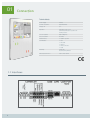
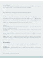
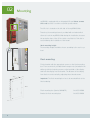
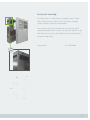
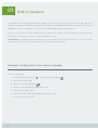
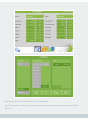
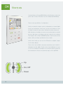
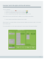
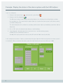
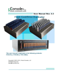
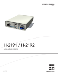
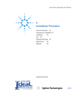
User Manual myGEKKO Slide V 0.1 Last update: November 2013 All software-related descriptions refer to the software V1279. We recommend to update older versions of the system.Small deviations in the description because of software changes are possible.All listed brands and logos are registered trademarks of their respective owners. Copyright: All rights reserved. Without the the prior written permission of the publisher, no part of this document for any purpose, be reproduced or transmitted, and regardless of any form or by any means, electronic or mechanical, this is happening. If this publication is made available on media by Ekon GmbH, GmbH Ekon grant permission, copies of the information contained in this file is only for private use and not to download or print for redistribution. No part of this publication may be changed, modified or used for commercial purposes. Ekon is not liable for damages resulting from the use of an illegal modified or altered publication. The devices comply with the relevant guidelines and standards of the EU. 2 Table of Content 01 Connection................................................................................4 1.1 Interfaces . . ............................................................................................................ 4 02 Mounting..................................................................................6 03 Built-in speakers.......................................................................8 04 Shortcuts................................................................................10 05 Notes......................................................................................13 Safety guidelines.........................................................................14 3 01 Connection Technical data 1.1 Interfaces Connection overview 4 Power supply 24VDC Current consumtion 650mA@24VDC Display size 8,4” Operation Capacitive touch screen 9 LED fields with quick operation and warning function Screen resolution 800 x 600 pixels Colour resolution 16 million Audio interface 2 x built-in speakers Schnittstellen 1 x Lan 1 x Line-Out 1 x RS232 1 x RS232 / RS485 1 x USB Mounting Cavity wall Flush mounting with box Dimensions W x H x D 220 x 320 x 20 mm Com Port 1 (RS232) Com Port 1 is a RS232 interface of the myGEKKO. It allows you to connect every RS232 device which is compatible with the myGEKKO or RS485 device to the RS485/RS232 converter (Art. ACC-RS401). LAN Via the LAN interface, the myGEKKO can be connected to a network using a LAN cable. USB The myGEKKO is equipped with 2 USB interfaces, each of with can switch up to 500mA. A USB port is connected to the USB interface on the front of the faceplate with an extension cable (black). If you need an additional interface, e.g. for a USB flash drive or a USB for 4 x RS232 converters, you have to install a USB hub (Art. ACC-USBXX). The display is connected to the other USB port (gray cable). NEVER disconnect the display while the USB slot is running. The display must always be connected directly to the USB port (never with the USB hub). CombiCon Com Port2 (RS485): CombiCon is equipped with a RS485 interface (Com Port 2). Here you can connect every R485 device which is compatible with myGEKKO. Pay attention, when a device is connected to Com Port 2 (RS232), the Com Port 2 (RS485) (CombiCon) can not be used anymore. Operating voltage: myGEKKO requires an operating voltage of 24VDC. This operating voltage has to be connected to CombiCon. LineOut: A LineOut signal (left and right) can be taken from the CombiCon. Pay attention: in order to avoid interferences on the Lineout signal, the ground must be connected to LINEOUT_GND. You can find further information in the technical manual Music Multiroom. Com Port 2 (RS232) In addition to Com Port 1, the device is equipped with another R232 interface (Com Port 2). It allows you to connect every RS232 device which is compatible with the myGEKKO or RS485 device to the RS485/RS232 converter (Art. ACC-RS401). Pay attention, when a device is connected to Com Port 2 (RS485), the Com Port 2 (RS232) can not be used on CombiCon anymore. For the assignment, see the connection overview. 5 02 Mounting myGEKKO is equipped with an integrated SD card. Never remove this card, because it contains essential operation data. The SD slot is located on the left side of the myGEKKO Slide. Therefore, the mounting frame is provided with an indent which allows to hook the myGEKKO Slide during the installation, because the protective bars of the SD slot stick out a little bit. Take this in account during the installation of the frame! Ideal mounting height: The mounting height should be chosen according to the user’s eye level. Flush mounting: Fix the bracket with the appropriate screws on the flush mounting box. Then screw the 4 provided 3mm-hexagon nuts (included in the delivery) with the fastening screws on the backside of the display and hook the display into the bracket. The distance of the display from the box can be varied by adjusting these thread screws. Important: The flush mounting box has to be mounted flush to the final rendering. 6 Flush mounting box (Gewiss GW48672) Art. ACC-BOX01 Bracket for flush mounting box Art. ACC-RBX01 Cavity wall mounting: The cavity wall box is fixed with four clamping screws or metal claws located on the two sides. First of all, turn the clamping screws so that the claws are turned inwards. Then position the box in the desired place. Now turn the claws outwards and tighten them in order to fix the cavity wall box on the wall. After that, you can hook the display into the mounting frame using the thread screws. Cavity wall box Art. ACC-BOX10 7 03 Built-in speakers The myGEKKO Slide is equipped with built-in speakers. They are located on the left side and on the right side of the housing. The speakers are directly connected to the LineOut of the myGEKKO, but have to be activated, which means switched on and off, via software. This happens activating the digital output of the amplifier: If there is only one music zone, the amplifier can be assigned to the output in the IO Configuration of the music zone. The speakers are switched on as soon as the music begins to play. Pay attention, the amplifier can be assigned just once to an output! If there are more music zones or you use voice commands for the speakers, the output has to be connected using an OR-logic. Example: Configuration of the onboard speaker Log in as configurator. 1. Change to the System menu and select the system Music 2. Select the first free field 3. Change to the IO configuration 4. Assign a name by tapping the green bar on top 5. Select a source and a mixer. 6. Select the “output” Onboard->Amplifier->Amplifier->on/off 7. Confirm the entries with “Ok” 8 Now the onboard speaker of the myGEKKO Slide is configurated. You can learn how to set music zones, assign push-buttons and create playlists in the technical manual Music Multiroom. 9 04 Shortcuts A special feature of the myGEKKO Slide are the 9 buttons on the front panel. Each of these LED buttons can be configurated individually. There are two possibilities of configuration: On the one hand, the button can be configurated as a normal digital input (e.g. push-button). In this way, you can use the buttons to turn the lights on and off, start actions, activate the alarm system, etc. With the buttons 4 and 6 you can not only turn the lights on and off, but also dim them up and down and open and close the shutters. This happens with a simple UP/DOWN gesture. Tap the center of the buttons with your finger and slide them up or down. On the other hand, you can use the LED buttons as digital outputs for the status display. Three colours are available: red, green and yellow, each of which is dimmable from 0 to 100%. Thanks to this visual feedback, it is easy to see if for example the windows are closed, the alarm system has been activated or if there are alarm messages on the myGEKKO. Up On / Off Down 10 Example: Switch the lights with the LED buttons Log in as configurator. 1. Change to the System menu and select the system Light 2. Tap the first free light and then change to the IO configuration 3. Select as “Button ON” and “Button OFF” Onboard->Button9->Button->on/off Now the button 9 can be used as light switch. In addition, you can activate the status display. 1. Select as switching output Onboard->Button9->Green->0..100 When the light is on, the button 9 lights up with green light with a 100% intensity. When the light is off, the button doesn't light up (=0%). The second possibility is to set the output as dim-output 1 in order to dim the LED between 0 and 100%. 11 Example: Display the status of the alarm system with the LED buttons Log in as configurator. 1. Change to the System menu and select the system Alarm 2. Change to the IO configuration The difference between status display and activity display is the following: the activity display considers the start delay, too. This means that the button lights up only when the alarm system is effectively running (=activation+delay time). The status display doesn’t consider the start delay and the button lights up immediately (=activation without delay time). 3. Clic on “DO” next to the desired status display or activity display. 4. Select Onboard-> desired button(1-9)-> desired colour-> and the glowing property 0..100 (LEDs are switched off and on) or 10..100 (LEDs light up with 10% intensity with OFF and with 100% intensity with ON) In the example below, button 1 lights up permanently with green light with 10% intensity when the alarm system is not activated. When you activate the alarm system, the light intensity increases from 10% up to 100%. 12 05 Notes 13 Safety guidelines Intended use: The control is approved for use in private and commercial domestic automation systems. The control may only be used for the intended purpose. This implies the observance of all the operating-, mounting- and service instructions prescribed by the manufacturer. A use contrary to the intended purpose or unauthorised modifications of the control release the manufacturer from liability for any resulting damage. The risk is carried by the user alone. The control may only be used, serviced and maintained by persons who are familiar with the device and have received instruction concerning the risks involved. The applicable VDE/CEI prescriptions as well as every generally accepted rules for the safe operation of machinery must be observed! This device has been developed and produced in order to ensure your personal safety. However, an improper use can lead to the risk of electric shock or fire. Please observe the following general rules during installation, use and maintenance in order to allow the protective devices integrated in the display to operate properly. Read the operating instructions and the safety guidelines before the commissioning and bear them in mind when you use myGEKKO. Follow the instructions: Follow the indications included in this operating manual or in other documents of the additional components. Connection and installation: The control must only be connected to the electricity grid by a local qualified electrician. In case of failures which cannot be solved by a qualified electrician, please inform the myGEKKO customer service! The remote control (remote switching), setting, control and/or regulation of a control device using a command or carried out in a mounting location which is out of sight of the device is only allowed with regard to the foreseen security measures. Mounting: Carry out the installation of the control in accordance with the mounting instructions! Before you carry out the commissioning, ensure that the control doesn’t get in contact with inflammable objects. Periodically check the log file in order to verify if there are warnings or alarm messages. The display must be installed in a dry place protected from direct wetness. Water droplets should never drip onto the display. Supply voltage: The device must work with the specified supply voltage. No changes or modifications: Don‘t carry out changes or modifications of the device which are not expressly approved by the competent authority for the regulatory compliance. Unauthorized changes or modifications may void the user’s authority to operate the device. Use only original spare parts! Unauthorised modifications of the control are not allowed! Don't remove the device from the bracket: There are components that carry dangerous voltages. Contact your electrician if the device doesn't work properly. Do not use hard objects for the handling: Avoid wiping or touching the display with hard objects; this could scratch, impair or even damage it permanently. Cleaning: For this purpose, use a slightly damp (not wet) soft microfiber cloth. Do not apply cleaning sprays directly on the screen; part of the spray could penetrate into the housing apertures and cause electric shocks. Do not use chemical cleaning agents which are not suitable for the cleaning of VGA displays. Ambient temperature: The ambient temperature must lie between 0 and 40°C. Avoid direct sunlight: Install the device in a position where it will not be exposed to direct sunlight, which can permanently damage the display. 14 This device is not intended for use by persons (including children) with reduced physical, sensory or mental capabilities, or lack of experience and knowledge, unless they have been given supervision or instruction concerning use of the device by a person responsible for their safety. Children are to be supervised in order to make sure that they do not play with the device. The violation of the safety guidelines can void the warranty. The proper use of myGEKKO in technical facilities does not exclude the appliance of all required and useful safety precautions. myGEKKO cannot be used in safety installations! No responsibility is taken for the following damages: • Non-observance of the safety guidelines • Damages and consequential damages of the plant caused by improper parametrization or installation • Damages and consequential damages of the plant caused by improper operation of the plant • Damages and consequential damages of the plant caused by overvoltage • Damages and consequential damages of the plant caused by natural events (fire, static discharge, …) • Loss of configuration files and parameters. Make a regular backup of the configuration data and parameters. (see operating manual) lease transmit the safety guidelines mentioned above to your final customer. 15 myGEKKO is a product born from a longlasting experience and development all over Europe – with partners in your neighbourhood. Italy Germany Switzerland Austria www.my-gekko.com A first class product Europe! A first classof product of Europe! The result of aThe close collaboration between result of a close collaboration between Italy, Switzerland Germanyand Germany Italy,and Switzerland 16 Netherlands