1
W&T
Instruction Manual
W&T
COM-Server
Rel. 3.0, 12 / 96
Models
#58001 / #58004
Display
#58201
Compact
#58301 / #58304
19"
#58401 / #58404
OEM
W&T
Copyright 06/2002 by Wiesemann & Theis GmbH
Subject to error and alteration
Since it is possible that we make mistakes, you mustn't use any of our statements without
verification. Please, inform us of any error or misunderstanding you come about, so we
can identify and eliminate it as soon as possible.
Carry out work on or with W&T products only to the extent that they are described here
and after you have completely read and understood the manual and guide. We are not
reliable for unauthorized repairs or tampering. When in doubt, check first with us or with
your dealer
Introduction and overview
W&T
Introduction and overview
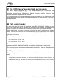
The variety and complexity of ways in which the W&T COM-Server can be used requires
comprehensive documentation of the device. It is not necessary to read the entire manual,
however, in order to be able to use its very special applications.
The manual is divided into six main chapters, each of which covers a specific topic.
Part 1: Connections and configurations
This chapter describes the options for connecting the device. Here you will find
everything about the hardware, such as the location and specification of the
connections, arrangement of jumpers, views of circuit cards, including schematic
depictions of the different configurations of the W&T COM-Server.
Part 2: Displays and settings
This chapter describes the organizational principle of the menu for software
configuration of the device, as well as all of the operating and error messages and the
display outputs of the W&T COM-Server. Concrete descriptions are provided of all
configurations which are independent of the type of network in use, such as
configuration of the serial ports and software updating of the device.
Part 3: The TCPIP protocol
This chapter contains all of the configurations and modes for use when you are working
with the TCP/IP network protocol and connection is to be established with another
network station (not a W&T COM-Server) .
Part 4: The IPX protocol
We have kept this chapter very short, since it is only relevant for those who have
implemented their application with the Netware Development Kit (item no. #58113).
You will find comprehensive instructions in the documentation for that package.
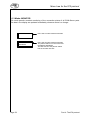
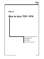
Part 5: Box to box TCP / IPX
This chapter describes the possibilities for linking W&T COM-Servers together for the
two network protocols (TCP/IP and IPX). If you have decided on the TCP/IP protocol,
start by reading Chapter 3.1 Quick installation, and then read this part of the
instructions.
Part 6: Expanded TCP/IP socket functions
This chapter is very specialized, and of interest only to those who will use the W&T
COM-Server in the TCP/IP socket server or client mode (see Chapter 3.6). It contains
documentation of all of the additional socket functions of the W&T COM-Server and
instructions for socket programming in general.
W&T
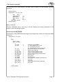
Table of contents
Table of contents
Part 1
Page
Connections and hardware variants . . . . . . . . . . . . . . . . . . . . . . . . . . . . . .
1
1.10
Tasks of the W&T COM-Server
1.20
External connections of the W&T COM-Server
...............
3
1.30
Control elements of the W&T COM-Server . . . . . . . . . . . . . . . . . . . . .
7
1.40
Part 2
...................................
Hardware variants of the W&T COM-Server . . . . . . . . . . . . . . . . . . .
Displays and settings
2
7
..................................................
13
Displays . . . . . . . . . . . . . . . . . . . . . . . . . . . . . . . . . . . . . . . . . . . . . . . . . . . . . . . . . . . . . . . . . .
14
2.20
Configuring the W&T COM-Server
19
2.30
Special key functions
26
2.40
Updating the W&T COM-Server software . . . . . . . . . . . . . . . . . . . . . . .
27
2.10
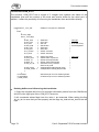
Part 3
The TCPIP protocol
...............................
.....................................................
31
3.10
Quick installation
......................................................
33
3.20
Menu tree for the TCPIP protocol . . . . . . . . . . . . . . . . . . . . . . . . . . . . . . . . .
34
3.30
Protocols for the TCP/IP suite
.....................................
40
3.40
Data transfer via FTP
................................................
40
3.50
Data transfer via TELNET . . . . . . . . . . . . . . . . . . . . . . . . . . . . . . . . . . . . . . . . . . .
45
3.60
Data transfer via TCPIP sockets
46
3.70
SLIP modes . . . . . . . . . . . . . . . . . . . . . . . . . . . . . . . . . . . . . . . . . . . . . . . . . . . . . . . . . . . . .
52
Part 4
4.10
Part 5
The IPX protocol
.........................................................
55
Menu tree for the IPX protocol . . . . . . . . . . . . . . . . . . . . . . . . . . . . . . . . . . . . .
56
Box to box TCP / IPX
...................................................
59
5.10
Menu tree for box to box TCP/IPX . . . . . . . . . . . . . . . . . . . . . . . . . . . . . . . .
60
5.20
Box to box operation . . . . . . . . . . . . . . . . . . . . . . . . . . . . . . . . . . . . . . . . . . . . . . . . . .
64
5.30
Setting the box to box mode (IPX) . . . . . . . . . . . . . . . . . . . . . . . . . . . . . . . .
65
5.40
Setting the box to box mode (TCPIP) . . . . . . . . . . . . . . . . . . . . . . . . . . . .
68
5.50
IP bus master / slave operation . . . . . . . . . . . . . . . . . . . . . . . . . . . . . . . . . . . .
70
iii
W&T
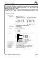
Table of contents
Part 6
Expanded TCP/IP socket functions . . . . . . . . . . . . . . . . . . . . . . . . . . . . . . . .
73
6.10
Control and service ports of the W&T COM-Server . . . . . . . . . .
74
6.20
Port control socket . . . . . . . . . . . . . . . . . . . . . . . . . . . . . . . . . . . . . . . . . . . . . . . . . . . .
74
6.30
Resetting the COM port status via socket
79
6.40
Software resetting of the COM-Server via socket
............
79
6.50
EEPROM uploading and downloading via socket
............
80
Overview of port (socket) numbers . . . . . . . . . . . . . . . . . . . . . . . . . . . . . . . . . . .
81
Technical data . . . . . . . . . . . . . . . . . . . . . . . . . . . . . . . . . . . . . . . . . . . . . . . . . . . . . . . . . . . . . .
83
APPENDIX
......................
iii
W&T
Table of contents
iii
W&T
Part 1
Connections and
hardware variants
Network connections
Serial connections
Internal connections
Controls
Hardware variants
Part 1: Connections and hardware variants
Page 1
W&T
Tasks of the W&T COM-Server
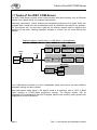
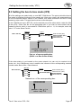
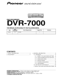
1.1 Tasks of the W&T COM-Server
The W&T COM-Server permits direct communication with serial devices over an Ethernet
network from a great variety of computer architectures.
Measuring instruments, control devices and peripheral equipment of all types which are
equipped with a serial port can be addressed over an Ethernet LAN without any problem.
The connections can use the same cable as an existing network without impairing the
operation of the latter; existing repeaters, bridges or routers can be used without any
problem.
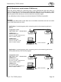
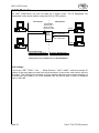
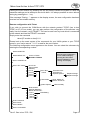
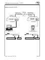
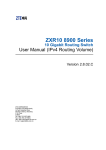
Application diagram "RS232 device <> COM-Server <> User application"
IPX
ethernet
card
RS232
cable
IPX
driver
W&T
COM-Server API
user
application
Ethernet
UNIX
RS232
device
RS232
device
W&T
COM-Server
ethernet
card
TCP/IP
TELNET, FTP,
TFTP, ARP
user
application
Box to Box
W&T
COM-Server
RS232
device
RS232
device
Every COM-Server provides up to four independent serial ports, which can have different
parameter settings for each channel.
Data transmission takes place in full duplex mode at a maximum rate of 153.6 k Baud
(4-port version) or 57,600 Baud (single-port version). The Display version, with its
integrated LCD combined with the built-in keypad, permits user-friendly, menu-guided local
configuration of the COM-Server.
Page 2
Part 1: Connections and hardware variants
W&T
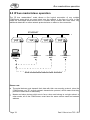
External connections of the W&T COM-Server
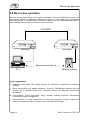
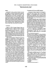
1.2 External connections of the W&T COM-Server
The W&T COM-Server should be placed in a location where the maximum permitted cable
run of 15 m to the serial devices and 185 m or 100 m on the network side are not
exceeded. If this is not possible in individual cases, line drivers can be used for the serial
port; depending upon the model, these permit transmission distances of up to 1000 m
(W&T #80001). The use of Ethernet repeaters and hubs makes it possible to expand the
length of the network to as much as 2.5 km (W&T #55615).
Please note that none of the plug-in connectors may be inserted unless the terminal
devices are turned off. The locations of the individual connections can be found in the
illustrations in Section 1.4 (Hardware variants of the W&T COM-Server).
The self-adhesive hook-and-loop tape which is included with some versions makes it
possible to mount the COM-Server directly on a flat surface, such as the vertical side of a
printer.
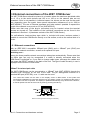
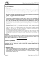
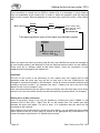
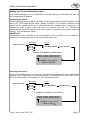
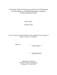
1.2.1 Ethernet connections
Both an IEEE 802.3 compatible 10Base2 port (BNC) and a 10BaseT port (RJ45) are
available for network connection, as well as an optional AUI port.
Switching over...
among the three possible network connections takes place automatically. Please note that
the cable type can only be recognized if a cable is actually connected when the
COM-Server is switched on. If you wish to change cable types, exchange the cables and
then press the RESET switch on the back of the unit. The type of cable currently in use is
displayed on the screen in RUN mode.
10BaseT for twisted pair cable
The W&T COM-Server can be connected to a 10BaseT hub (W&T #55603) through the
shielded RJ45 connector on the rear of the case. The pin assingments conform to a
standard MDI port (AT&T258), so a 1:1 cable can be used.
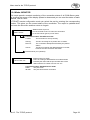
The current link status can be seen on the display screen in RUN mode. If the system has
successfully established a connection with the hub, the display "Cable: TP" appears at this point; if
not, "Cable: Link fail" is reported. The display is updated automatically every 60 seconds. However,
a manual update can also be forced at any time by pressing the OK key.
8=NC
1=Rx+
7=NC
2=Rx3=Tx+
4=NC
6=Tx- 5=NC
RJ45 connector (pinout according to AT&T256)
Part 1: Connections and hardware variants
Page 3
W&T
External connections of the W&T COM-Server
10Base2 for coaxial cable
The BNC connector can be used to link the W&T COM-Server into a 10Base2 network
segment.
When using conventional technology with BNC T-connectors, please be aware that it may
be necessary to disconnect the cable and that this can cause difficulties for other users.
Before connecting the COM-Server please consult with the responsible network
administrator.
Important!
When the COM-Server is placed at the end of the segment, it is essential to terminate
the cable with a 50Ω
Ω terminator.
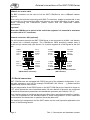
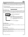
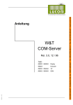
Network connector: AUI (optional)
The AUI connector permits the W&T COM-Server to be connected to a MAU and thereby
be linked into a network segment. The COM-Server OEM short/long models have a
double-row pin contact strip (see Section 1.4.4) which supplies all of the signals for the AUI
port.
5=RX+
6=GND
7=n.c.
8=n.c.
15=n.c.
14=n.c.
13=+12V
4=n.c.
3=TX+
2=CD+
1=n.c.
9 =CD10=TX11=n.c.
12=RX-
AUI pinout
(DB15 female connector)
12=RX11=GND
10=TX9 =CD-
1=GND
2=CD+
3=TX+
4=GND
13=+12V
14=GND
15=n.c.
16=GND
9
16
1
8
8=GND
7=n.c.
6=GND
5=RX+
OEM version: PCB pin header connector
(AUI interface)
1.2.2 Serial connectors
W&T COM-Servers are equipped with RS232 as part of the standard configuration. If you
use other modules in your unit (for example, RS422/485, LWL, 20mA, .... ), please read the
supplemental module instructions.
The pin assignments of the RS232 ports on the W&T COM-Server are identical to those on
a PC, which permits the use of standard cables. Be sure that all of the ports are configured
for identical transmission parameters and handshake protocols (see Section 2.2.2.3).
Since interface ports on peripheral devices are often highly manufacturer-specific in design,
it may not be possible to use standard cables in some configurations. In such cases the
documentation for the devices in question should be referred to.
The details of pin assignment and the W&T cables for the most important applications are
shown in the following section.
Page 4
Part 1: Connections and hardware variants
W&T
External connections of the W&T COM-Server
Direction
Signal
1
IN
DCD
2
IN
RxD
Receive Data
Data input
3
OUT
TxD
Transmit Data
Data output
4
OUT
DTR
Data Terminal
Ready
+12V with active connection to PC
(LOCK/UNLOCK)
5
--
GND
Signal Ground
--
6
IN
DSR
Data Set Ready
Data transmission only at +3...12V
7
OUT
RTS
Ready To Send
Handshake output
+12V = Ready to receive data
-12V = Not ready to receive data
8
IN
CTS
Clear To Send
Data transmission only at +3...12V
9
IN
RI
Ring Indicator
Ignored
(1)
Description
Default function (1)
Pin
Data Carrier Detect Ignored
can be modified temporarily by the specific software
Pin assignments and functions, RS232 / DB9 connector
5
6
8
2
3
5
6
7
20
Part 1: Connections and hardware variants
20
2
3
6
7
8
5
4
COM-Server <> Modem
#1198x
1
2
3
4
5
6
7
8
9
8
3
2
20
7
6
4
5
22
DB25 male
2
3
4
DB25 male
DB9 female
COM-Server -> Printer
#1189x
1
2
3
4
5
6
7
8
DB25 female
DB9 female
4
3
2
1
5
6
8
7
COM-Server <> 25 pin PC
#1179x
DB9 female
1
2
3
4
5
6
7
8
DB9 female
DB9 female
COM-Server <> 9 pin PC
#1199x
Page 5
W&T
External connections of the W&T COM-Server
1.2.3 Power supply
The power supply depends upon the model of W&T COM-Server.
W&T COM-Servers with Display (#58001, #58004)
The W&T COM-Servers have a built-in power adapter. Power is drawn through the
supplied power cord and matching connector on the back of the case.
Because this power adapter is designed for an input voltage range of 110V~ to 230V~,
the W&T COM-Server can also be used equally well in countries with other line
voltages.
W&T COM-Server Compact (#58201)
The W&T COM-Server Compact includes a special plug adapter (see Technical data in
the Appendix), which connects to the matching input (DC power jack) on the back of
the case. This adapter has a fixed input voltage of 230V.
W&T COM-Server 19" OEM (#58301, #58304)
These COM-Servers are able to get their power through the VG strip. Jumpers on the
board allow it to be set up for the most common bus standards (see Section 1.4.5).
W&T COM-Server OEM short / long (#5840x)
These versions allow various power supply options. Power can be supplied through
one of the two power adapters or through a proprietary design. The connections can be
taken from the illustration in Section 1.4.4.
Page 6
Part 1: Connections and hardware variants
W&T
Control elements of the W&T COM-Server
1.3 Control elements of the W&T COM-Server
W&T COM-Servers are supplied in a variety of different models. The control elements are
not identical, nor are they positioned uniformly on the various models. The following pages
show sketches of the front and rear plates (if present) for all of the models.
1.3.1 Reset button
This button resets the internal microprocessor, thereby restarting the W&T COM-Servers.
Since all of the data stored in the COM-Server are lost when this happens, caution should
be used when pressing this button.
To reduce the risk of inappropriate operation and the resultant loss of data, the Reset
button is recessed into the back of the case.
1.3.2 Front control panel (models #58001, #58004)
The operating parameters for the W&T COM-Server can be set through the keypad which
is integrated into the faceplate. Using the directional keys (↓↑→ ←), the user can move
around in the menu structure described in the following chapters. Any changes or
selections which are made must be confirmed with the OK key in order to take effect.
1.4 Hardware variants of the W&T COM-Server
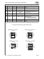
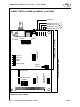
1.4.1 W&T COM-Server with Display #58001, #58004
Mode Run 08:30
Cable: Coax
Status
OK
Power
Error
A Port
W&T
serial port A
COM-Server
#58001
Front panel #58001
Mode Run 08:30
Cable: Coax
Status
OK
D C B A
W&T
serial port D
serial port C
serial port B
Power
Error
Port
serial port A
COM-Server
#58004
Front panel #58004
Part 1: Connections and hardware variants
Page 7
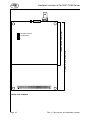
W&T
Hardware variants of the W&T COM-Server
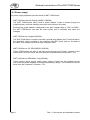
Reset
RJ45
BNC
Power jack
Rear panel #58001,#58004
W&T
= OK
= network error
= ser.data format
= ser. handshake
= self test
Blink code Error LED
off
1x
2x
3x
on
Blink code Status LED
off = Standby
on = Error
blink = Connected
flash = Data
Error
serial port
Power
Status
COM-Server
#58201
1.4.2 W&T COM-Server Compact #58201
Front panel #58201
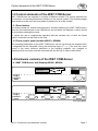
Reset
RJ45
BNC Power jack
Rear panel #58201
1.4.3 W&T COM-Server 19´´ OEM #58301, #58304
serial port D
serial port C
serial port B
#58304 only
serial port A
#58301
Power
Port D
Port C
Port B
Port A
Ethernet
10Base2
10BaseT
Reset
COM-Server
W&T
Blink code Status LED
off = Standby
on = Error
blink = connected
flash = Data
Blink code Error LED
off = OK
1x = Network error
2x = ser. data format
3x = ser. handshake
on = self test
Front panel #58301 and #58304
Page 8
Part 1: Connections and hardware variants
W&T
Hardware variants of the W&T COM-Server
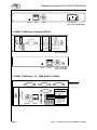
1.4.4 W&T COM-Server OEM short #58401 / long #58404
Status/Error Port A
Status/Error Port B
Status/Error Port C
Status/Error Port D
LEDs
reset
button
16
8
1
power supply 5V / 12V
1
VCC +5V
VCC +5V
GND
GND
SHD or +12V (for AUI only)
SHD SHIELD
interface module
socket port A
AUI connector
(optional)
jumper 1
jumper 2
interface module
socket port C
jumpers
c
b
1
interface module
socket port A
1
interface module
socket port D
interface module
socket port B
1
1
COM-Server OEM long #58404
RJ45
COM-Server OEM short #58401
BNCconnector
5V GND
9
#58404 only
Power LED
5
1
a
c
b
a
32
1
Component side of board
Part 1: Connections and hardware variants
Page 9
W&T
interface module
socket port A
1
1
COM-Server OEM long #58404
COM-Server OEM short #58401
Hardware variants of the W&T COM-Server
c
b
a
32
Solder side of board
Page 10
Part 1: Connections and hardware variants
W&T
Hardware variants of the W&T COM-Server
1.4.5 Internal connections of the W&T COM-Server
Now let us describe the connectors which are located directly on the board. It is only
necessary to know the details of these connections if you are working with the OEM version
of the COM-Server. The locations of the connectors on the board can be seen from the
illustrations on the preceding pages.
Contact assignments of the module sockets
1
2
3
4
5
6
7
8
16
15
14
13
12
11
10
9
Description
Default function (1)
5V
Power supply 5V
--
RI
Ring Indicator
Ignored
IN
RxD
Receive Data
Data input
4
OUT
TxD
Transmit Data
Data output
5
--
n.c.
not connected
--
6
IN
CTS
Clear to Send
Handshake input
Low: data transfer, High: stop
7
OUT
DTR
Data Terminal Ready
Low with active connection to PC
8
IN
DSR
Data Set Ready
Handshake input
Low: data transfer, High: stop
9
OUT
RTS
Ready to Send
Handshake output
Low: ready to receive data
High: not ready to receive data
10
IN
DCD
Data Carrier Detect
Ignored
11
OUT
12V
+12V
--
12
OUT
GND
Signal Ground
--
Pin
Direction
Signal
1
OUT
2
IN
3
(1)
can be temporary modified by software
Contact assignments of the VG strip
The 19" OEM COM-Servers (#58301, #58304) get their power through the VG strip.
Depending upon the bus system which you are using, jumpers a-c in the appropriate row of
the jumper strip must be set on the board in order to provide power for the COM-Server.
Connector pin
VG strip
Input
COM-Server
Default (all three jumpers of a
row closed)
Jumper
A
B
C
A
B
C
Jumper Row 1
9c
32c
31c
GND
+5V
+12V
Jumper Row 2
2b
1b
n.c.
GND
+5V
+12V
VME bus J2
Jumper Row 3
32c
31c
3c
GND
+5V
+12V
Multibus II
Jumper Row 4
32c
1c
13a
GND
+5V
+12V
ECB bus
Jumper Row 5
32c
29a
9a
GND
+5V
+12V
BUS7ISA
Part 1: Connections and hardware variants
VME bus J1
Page 11
W&T
Page 12
Notes
Part 1: Connections and hardware variants
W&T
Part 2
Displays and
settings
Displays
Error messages
Overview of menu tree
Configurable serial ports
Special key functions
Software updating
Part 2: Displays and settings
Page 13
W&T
Displays
2.1 Displays
The W&T COM-Servers have a power LED, and for each serial port a status LED and an
error LED.
In addition, the Display versions (#5800x) have a 2x16 character LCD screen for displaying
error and status messages.
2.1.1 LED displays
Power LED
Indicates connection to the power supply. If the LED fails to light up, please check to
make sure that the plug-in adapter is properly connected, or that the line cord is
properly connected and in good condition (with built-in adapter).
In the case of 19" OEM COM-Servers (#5830x) please be sure to check the proper
setting of your bus system in the jumper strip on the board (see Section 1.4.5).
Status LEDs
Flash whenever there is network activity (sending and receiving) at the corresponding
W&T COM-Server port. In the case of reception, the functioning of the LED pertains
exclusively to data and control packets which are addressed directly to the
COM-Server.
Periodic blinking indicates that the corresponding serial port has a valid connection
with another network participant. When useful data are passing over the connection the
LED flashes briefly.
On Display versions only (item no. 5800x):
Error LEDs
Indicate present errors or errors in memory. In this case an error text, the time of the
error, and the number of the responsible RS232 port (if any) can be obtained from the
LCD screen.
All other versions:
Error LEDs
By means of different blink codes, the error LEDs indicate the following error conditions
at the corresponding port:
1 blink of all error LEDs = Check network
If the 10BaseT port is being used, the COM-Server is unable to receive a link pulse from a hub.
Check the cable or the hub port. If you are using the BNC connector, the coax cable should be
checked for correct termination or a possible break or short circuit in the cable. When using an AUI
connector please check its connection to a MAU.
Page 14
Part 2: Displays and settings
W&T
Displays
2 blinks = check serial data format
At least one character was received at the corresponding port with a parity or
framing error, or the data register of the serial receiving module was written to,
even though the prior character had not been read out. Check the correctness of
the serial parameter settings, the handshaking procedure or the connecting cable.
3 blinks = check serial handshake
The serial device connected to the particular port is not reacting to the handshake
stop signal set by the COM-Server and is continuing to send data. This can result
in overwriting of the serial ring buffer and consequently in the loss of data. Check
to see that the handshake configuration of the devices is correct and that the
connecting cable is properly wired.
all error LEDs on = self-test error
The self-test which is performed after every Start or Reset of the COM-Servers did
not finish normally.
This error can occur if you interrupted a software update early and it was not
possible to transfer the complete operating software. The COM-Server is no longer
operable in this state. Repeat the software update over the network with TFTP (see
Section 2.4.1).
If the only way you can perform the update is through the serial port, Jumper 1 on
the board (see illustration in Section 1.4.4) must be closed. Afterward press the
Reset button (see Section 2.4.2).
If the error cannot be corrected, or if it occurs independently without being
preceded by a software update, please send the unit to us.
2.1.2 Display error messages
The following section shows the error messages which can appear in the display, and
possible causes:
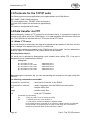
1.) "Link fail" (with twisted pair cable only)
Display:
Mode: RUN
13:00
Cable: Link fail
The network cable definition is set for the 10BaseT port, but no link pulse is being
received. The cause may lie in a defective 10BaseT cable or hub port. Another
possible reason is an incorrectly wired cable.
The display is either updated automatically every 60 seconds, or optionally
whenever the OK key is pressed.
Part 2: Displays and settings
Page 15
W&T
Displays
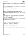
2.) "Cable open" (for coax or AUI cable only)
Display:
Mode: RUN
14:00
Cable open
The network segment is not correctly terminated (coax), or there is a discontinuity
in the connecting cable. With the help of a LAN Scanner (W&T #55506) the error
can quickly be found and corrected.
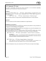
3.) Checksum error during self-test
Display:
ROM Test Error
NET FLASH-UPDATE
This error can occur if you interrupted a software update early and it was not
possible to transfer the complete operating software. The COM-Server is no longer
operable in this state. Repeat the software update over the network with TFTP (see
Section 2.4.1).
If the only way you can perform the update is through the serial port, Jumper 1 on
the board (see illustration in Section 1.4.4) must be closed. Press the Reset button.
The following message will appear on the display screen:
ROM Test Error
SERAIL FLASH-UPD
Repeat the software update via COM port A (see section 2.4.2). If the error cannot
be corrected, or if it occurs independent of any preceding software update, please
send the unit to us.
4.) CTS/DSR/RLSD Time Out
(only in connection with a Netware application IPX)
Display:
Port x
15:00
CTS/DSR/RLSD Time Out
The IPX-API function call SET_COM_STATE can be used to specify a timer value
for the W&T COM-Server for each of the three listed serial input signals. The timer
begins to run when the corresponding input goes LOW (-12V), and is reset as soon
as a HIGH (+12V) occurs. If that does not occur during the time period defined in
the configuration, this error message is issued. Possible causes can be
Page 16
Part 2: Displays and settings
W&T
Displays
a serial hardware device which is not connected, or which is unselected, defective
or incorrectly configured.
As delivered from the factory, the timers for all of the inputs are switched off.
5.) No halt on XOFF/DTR/RTS
Display:
Port x
16:00
No Halt on XOFF/RTS/DTR
The serial hardware device connected to the particular port is not reacting to the
stop signal set by the COM-Server and is continuing to send data. This can result
in overwriting of the serial ring buffer and consequently in the loss of data.
Check to see that the handshake configurations of the devices match and that the
connecting cables are wired correctly.
6.) Overrun Error
Display:
Port x
17:00
Overrun Error
The data register of the serial receiving module was written to, even though the
prior character had not been read out.
Since this is a purely internal process within the device, when this error message
occurs it is highly probable that there is a hardware error in the COM-Server.
7.) Parity Error
Display:
Port x
18:00
Parity Error
A character received at the corresponding serial port has the wrong parity bit or
none at all.
Please check to see that the transmission parameter configurations of the
COM-Server and the corresponding serial device match. Parity errors can also be
caused by the use of excessively long connecting cables.
Part 2: Displays and settings
Page 17
W&T
Displays
8.) Framing Error
Display:
Port x
19:00
Framing Error
A character received at the corresponding serial port does not fit into the time
frame which results from the transmission parameter settings (baud rate, start bit,
data bits, parity bit, stop bits).
In this case again please check to see that the configuration of the COM-Server
and the serial device match.
9.) PC disconnect (only in connection with a Netware
application IPX)
Display:
Port x
20:00
PC disconnect
If there is an active IPX connection to a control PC, the latter automatically asks for
the status of the W&T COM-Server every two minutes when there is no data traffic.
If this query is not made for more than 4 minutes, the W&T COM-Server
automatically breaks off the existing connection to the PC, in order to be available
for other participants who may be present. Any data present in the internal buffers
at this time are completely lost.
2.1.3 The error memory of the W&T COM-Server
The W&T COM-Server stores the last 10 errors which occurred, together with the time of
their occurrence and the port number, in a ring buffer. The most recent message at any
time is always the one currently displayed on the screen. The ↓ key can be used to call up
the earlier messages in order and read them on the screen.
Stored error messages are erased by pressing the OK key when they are displayed on the
screen. This causes the next earlier message to scroll automatically into the display.
Consequently if all of the memory locations of the W&T COM-Servers are occupied, then
the OK key needs to be pressed 10 times to delete all of the messages.
Page 18
Part 2: Displays and settings
Configuring the W&T COM-Server
W&T
2.2 Configuring the W&T COM-Server
Configuration of the W&T COM-Servers can be performed directly on the unit on the
models with integrated LCD display (#5800x). For all other models of the COM-Server the
procedures for configuring the device are dependent upon the type of network protocol
being used. Depending upon the protocol, it is possible to perform the configuration over
the network (with the help of TELNET or the IPX-API).
These options are described in the corresponding chapters of the manual (TCPIP protocol,
IPX protocol).
2.2.1 Nonvolatile memory
The W&T COM-Server stores all locally set configuration data in a special non-volatile
memory region. Once the data have been saved, they are activated again each time the
unit is turned on.
The transfer to non-volatile memory occurs when you have left that branch of the menu by
pressing the "OK" key (possibly more than once) and the message "Saving..." has
appeared on the display screen.
Following the illustration of the menu structure you will find a detailed example of modifying
the parameters.
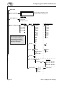
2.2.2 Overview of the display menus
This overview may be somewhat confusing at first. Play around a little bit at first with the
display by using the four arrow keys. As long as you press only these keys you can move
all around the menu without anything really being changed.
While the following section contains a thorough explanation of the individual menu items,
with a little skill you can also play at trying out how to use the menu. You would be best
advised to read the information about the filter in software handshaking, however.
Now that you know your way around, use the OK key now instead of the left arrow key in
order to really perform the settings. In order to prevent accidental operation, the OK key is
located on the front, clear to the right.
Part 2: Displays and settings
Page 19
W&T
Configuring the W&T COM-Server
Mode: RUN
Mode: MONITOR
Connect status information screen
A: FREE
(one information screen per port)
MENU TYPE
Mode: MENU TYP
Mode: COM SETUP
Protocol TCPIP
Protocol IPX
Box2Box TCP/IPX
COM Setu p
Port A
Port A
Baud
153,6k
115,2k
57600
38400
19200
9600
7200
4800
2400
1200
600
300
150
75
50
Data Bits
8
7
6
5
8
7
Parity
None
Even
MARK EVEN 0
Odd
MARK ODD 1
None
Even
Odd
Stop Bits
1
2
( Port B
.... )
( Port C
.... )
( Port D
.... )
(4 port version)
Save the actual configuration
to non volatile memory by
pressing the "OK" button
until the COM-Server shows
"Saving" in its display.
..
..
..
.
Handshake
FIFO Send/Rec:
(single port version)
57600
38400
19200
14400
9600
7200
4800
2400 . . .
1200
600
300
...
None
Hardware
XON/XOFF
8/ 8
16 / 16
32 / 56
Send/Rec.
Filter
Send ON / Rec ON
Send OFF / Rec ON
Send ON / Rec OFF
.Send
. . OFF / Rec OFF
without FIFO
disable
Page 20
Part 2: Displays and settings
W&T
Configuring the W&T COM-Server
..
..
Mode: SET TCPIP
Select MENU TYP "Protocol TCPIP" or "Box2Box TCP/IPX"
see manual part 3 (Protocol TCPIP) or part 5 (Box to Box)
Mode: SET IPX
Select MENU TYP "Protocol IPX" or "Box2Box TCP/IPX"
see manual part 4 (Protocol IPX) or part 5 (Box to Box)
Mode: INFO
Info
Node Number
Network Number
SOFTW Date/Rev:
BOOT BLOCK Rev.
Port A
( Port B
.... )
( Port C
.... )
( Port D
.... )
Port A
COM Setting
Mode: Password
Enter new Password
00000000
Mode: FLASH/EEP
Factory Defaults
Netw. FLASH-Upd
Serial FLASH-Upd
(numerical)
Example:
Starting from the RUN mode the modification of the baud rate for Port B from 9600 to 19200 baud
can be made through the following keyboard entries:
Key Display
Key
Display
Mode: RUN [time]
Cable: Coax
8.00
↑
Baud:
19200
1.00
↓
Mode: MONITOR
9.00
OK
Port B
Baud
2.00
↓
Mode: MENU TYPE
10.0
0
OK
Mode: COM SETUP
Port B
3.00
↓
Mode: COM SETUP
11.0
0
OK
Mode: COM SETUP
4.00
→
Mode: COM SETUP
Port A
12.0
0
↑
Mode: MENU TYPE
5.00
↓
Mode: COM SETUP
Port B
13.0
0
↑
Mode: MONITOR
6.00
→
PortB
Baud
14.0
0
↑
Mode: RUN
7.00
→
Baud
9600
Part 2: Displays and settings
Page 21
W&T
Configuring the W&T COM-Server
2.2.2.1 Mode: RUN
The W&T COM-Server is ready to establish a connection between the network and a serial
device in accordance with its configuration. The type of cable currently in use is shown in
the second line of the display.
2.2.2.2 Mode: MENU TYPE
To make the use of the menu as clear as possible, different branches of the menu are
blanked out depending upon the network protocol you are using.
In this menu you can set the protocol for which you wish to configure the COM-Server.
Naturally you can still configure the menu for both protocols by switching the MENU TYPE.
The TCPIP protocol
Confirm the selection with "OK." The menu "Mode: SET TCPIP" appears with all of the
client/server applications. The menu "Mode: SET IPX" is not visible.
The IPX protocol
Confirm the selection with "OK." The menu "Mode: SET IPX" appears. The menu
"Mode: SET TCPIP" is no longer visible.
Box to box TCP/IPX
Confirm the selection with "OK." Both menus appear, "Mode: SET IPX" and "Mode:
SET TCPIP," but in each case with only the settings which are relevant for the box to
box mode.
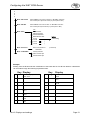
2.2.2.3 Mode: COM SETUP
The W&T COM-Server, like every serial device, has to be set to the communication
parameters of its partner. In this mode all of the RS232 parameters which are relevant for
operation can be configured separately for each port. Besides the usual settings for baud
rate, data bits, parity and stop bits, at this point the handshaking method and, for
multiple-port versions, the size of the FIFO buffer in the UART can be specified.
All changes take place immediately after you leave the respective menu level by pressing
the OK key.
Please note that storing the parameters deletes all data which is currently in the temporary
buffers of the W&T COM-Server.
Hardware handshaking
When hardware handshaking is used, the individual RS232 signals perform the
functions described in Section 1.2.2 according to the factory settings. Please note that
depending upon the version the meanings of the individual signals can be changed by
the particular application software at any time.
Page 22
Part 2: Displays and settings
Configuring the W&T COM-Server
W&T
Software handshaking
Software handshaking is carried out through the two ASCII characters (h11) = XON
and (h13) = XOFF. In this case the RTS output is permanently set at the factory for
+12V, and the CTS, DSR, DCD and RI are ignored.
A special feature are the four options under the menu item "Filters." These options
define whether the handshake bytes XON (h11) and XOFF (h13) are filtered out or are
communicated transparently.
Send filter = OFF
(XON/XOFF filter for data direction network → RS232)
All useful data, including the signals XON and XOFF, are output to the RS232 port without
filtering. It only makes sense to use this operating mode when the attached device is a
graphics printer, in whose data stream the handshake symbol must also be expected to occur.
Send filter = ON
If the characters XON or XOFF should occur within the useful data, they are filtered out by the
W&T COM-Server and are not forwarded to the terminal device. This operating mode is always
the one to choose for bidirectional RS232 connections, since otherwise problem-free data
communication is not possible.
Receive filter = OFF
(XON/XOFF filter for data direction RS232→
→ network)
The XON and XOFF characters sent by the serial device are transferred to the network along
with the actual useful data. This operating mode requires that the particular recipient on the
network have a special means for separating useful and control data.
Receive filter = ON
XON and XOFF characters sent by the serial device are treated as control bytes by the W&T
COM-Server and are not inserted into the network data stream. This ensures that the network
recipient receives only pure useful data.
2.2.2.4 Mode: MONITOR / SET IPX / SET TCPIP
In these menus all of the network-relevant parameters are set or displayed. The
configurations and operating modes which are to be set here differ considerably, according
to which protocol you are using. For this reason the descriptions will be found in the
chapters for the specific protocols: "The TCPIP protocol," "The IPX protocol," and "Box to
box TCP/IPX."
2.2.2.5 Mode: INFO
This item allows you to call up the device-specific parameters and the port parameter
settings for all of the serial ports.
Node Number
Displays the Ethernet address of the W&T COM-Server. This number is factory-set and
registered and cannot be changed.
Network Number (IPX protocol)
Displays the network address of the Netware network to which the COM-Server is
connected. If there is no Netware server in the network, then the display is blank.
Part 2: Displays and settings
Page 23
W&T
Configuring the W&T COM-Server
Software Date/Rev.
Displays the creation date and version number of the operating software stored in
FLASH memory.
BOOT BLOCK Rev.
Displays the creation date and version number of the boot block software.
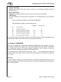
COM Setting
This item shows the current serial configuration of the selected port in the following
format:
[baud rate], [parity], [data bits], [stop bits], [handshake].
The handshake variable can take these values:
Send filter
Receive filter
[N]
No handshaking
----
----
[H]
Hardware handshaking
----
----
[X]
Software handshaking XON/XOFF
OFF
OFF
[S]
Software handshaking XON/XOFF
ON
OFF
[R]
Software handshaking XON/XOFF
OFF
ON
[SR]
Software-Handshake XON/XOFF
ON
ON
All of the other items of information listed in the INFO mode are network parameters, and
are described in detail in the instructions for the individual versions.
2.2.2.6 Mode: PASSWORD
Here you can specify an 8-character hexadecimal password, which protects the menu
items Mode: COM SETUP, Mode: SET IPX, Mode: SET TCPIP and Mode: FLASH/EEP
from unauthorized access. The factory setting is 00000000, which permits unrestricted
access to all of the configuration options of the COM-Server.
The numerical value is input with the cursor keys. The ←/→ keys determine the position of
the cursor within the number, which can then be incremented or decremented by means of
the ↑/↓ keys.
Important!
In order to reset or modify any of the parameters, including the password itself, you have to
know the old password. For this reason a written record of the password should always be
kept in a secure place.
Page 24
Part 2: Displays and settings
Configuring the W&T COM-Server
W&T
2.2.2.7 Mode: FLASH / EEP
In this mode you can start the software update or completely reset the nonvolatile memory
(EEPROM).
Factory Defaults
When you confirm this with "OK," all of the settings which you have stored are reset to
the defaults. The configuration then corresponds to the factory setting.
Important!
Resetting the nonvolatile memory leads to the loss of all settings which have been made, including
the IP address or IPX port numbers which have been assigned.
Net FLASH-Update
Before you activate this mode, terminate all currently active network connections. Then
confirm with "OK." The unit goes into the mode for update over the network. The
caption "NET UPDATE" appears on the display, and all of the green LEDs light up.
Important!
This mode blocks all other operating modes of the COM-Server, as well as the keypad. The only
way to exit from the update mode is to perform the update or press the Reset button. All currently
active connections, including any data, are lost.
Serial FLASH-Update
Before you activate this mode, terminate all currently active network connections. Then
confirm with "OK." The unit goes into the mode for update through serial port A. The
caption "SERIAL UPDATE" appears on the display, and all of the green LEDs light up.
Important!
This mode blocks all other operating modes of the COM-Server, as well as the keypad. The only
way to exit from the update mode is to perform the update or press the Reset button. All currently
active connections, including any data, are lost.
Part 2: Displays and settings
Page 25
W&T
Special key functions
2.3 Special key functions
For those W&T COM-Servers which have the display screen and keypad there are various
key combinations which enable you to deactivate operating mode settings separately for
each port, quickly and easily. Pressing the indicated keys returns the W&T COM-Server to
its basic state so that it can be reconfigured.
Clear Mode Port A:
Simultaneously press the "OK" and "←
←" keys and hold them down until the following
message appears:
Port A: CLR Mode
Press OK ...
Clear Mode Port B:
Simultaneously press the "OK" and "↑
↑" keys and hold them down until the following
message appears:
Port B: CLR Mode
Press OK ...
Clear Mode Port C:
Simultaneously press the "OK" and "→
→" keys and hold them down until the following
message appears:
Port C: CLR Mode
Press OK ...
Clear Mode Port D:
Simultaneously press the "OK" and "↓
↓" keys and hold them down until the following
message appears:
Port D: CLR Mode
Press OK ...
Page 26
Part 2: Displays and settings
Updating the W&T COM-Server software
W&T
2.4 Updating the W&T COM-Server software
Since the operating software of the W&T COM-Server is constantly undergoing further
development, the device also has a provision for performing a software update. When you
wish to add additional functions, you receive up to four files from us; these contain the new
firmware.
These files are named according to the following system:
58r3_0.2_1
File Nr. 1 von insgesamt 2 Files
Version 3.0
Artikel Nr. COM-Server #58xxx
There are two options for performing the update itself. If you have access to a UNIX
computer or a PC with a TCPIP kernel, you can carry out the software update with TFTP.
This goes much more quickly than updating through the serial port, and can be carried out
from practically any computer on which a TCPIP stack is activated.
The second option is to update through the serial port.
IMPORTANT:
Never force an interruption of the update process by pulling the line plug or pressing
the Reset button. The COM-Server is inoperable ollowing an incomplete update.
Never mix files with differing versions in their filenames. This will prevent the device
from working.
Transfer all of the files in sequence. The COM-Server automatically recognizes when
all of the files have been transferred and the new operating software is complete. It
then performs a reset by itself.
The software update has no effect on the configuration of the W&T COM-Server.
Part 2: Displays and settings
Page 27
W&T
Updating the W&T COM-Server software
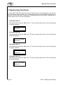
2.4.1 Network update of the W&T COM-Server software
This procedure requires a UNIX computer or a PC with a TCPIP stack, which supplies the
functions of the TFTP protocol.
The individual steps of the update process are described below. Please follow the
directions closely. An incomplete update will render the device inoperable!
Software update with TFTP
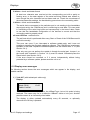
1. Select "Mode: FLASH/EEP - Netw. FLASH-UPD" in the menu and confirm with "OK."
The screen displays the message "NET FLASH-UPDATE" and all of the green status
LEDs are on. Now the COM-Server can only be addressed with TFTP. The menu is
no longer operable.
2. Now transfer the first file to the COM-Server with the command TFTP. Be sure to
use binary mode! While the data are being transferred over the network, the status
LED for Port A flashes. Afterward the COM-Server shifts into the programming mode
and all of the error LEDs light up. This process can take a few seconds. Wait until
the error LEDs go out and the status LEDs light up again.
Repeat this process for all of the files.
3. The COM-Server recognizes when all of the files have been transferred and
automatically performs a restart. If all of the green status LEDs are lit again after all
of the files have been transferred, repeat step 2 in its entirety. You may have omitted
a file. Duplicating transmission of a given file does not cause an error in the update
itself. The COM-Server waits until it has all of the needed files.
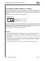
Example 1: SCO UNIX
You have received the following two files from us: 58r3_1.2_1 and 58r3_1.2_2. The new
operating software is version 3.1.
Enter the following commands at the prompts:
# tftp
tftp> connect [ip_number | host_name]
tftp> binary
tftp> put 58r3_1.2_1 [remote filename]
(remote filename = any letter)
Now wait until the green status LEDs light up again, and then transfer the second file.
tftp> put 58r3_1.2_2 [remote filename]
tftp> quit
#
Page 28
Part 2: Displays and settings
Updating the W&T COM-Server software
W&T
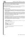
Example 2: Windows LAN Work Place
You have received the following two files from us: 58r3_4.2_1 and 58r3_4.2_2. The new
operating software is version 3.4.
Enter the following orders at the prompts:
(remote filename = any letter)
C:\ tftp -B 58r3_4.2_1 [ip_number | host_name] = [remote filename]
Now wait until the green status LEDs light up again, and then transfer the second file.
C:\ tftp -B 58r3_4.2_2 [ip_number | host_name] = [remote filename]
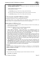
2.4.1 Serial update of the W&T COM-Server software
This procedure requires a PC with a configurable serial port.
The individual steps of the update process are described below. Please follow the
directions closely. An incomplete update will render the device inoperable!
Software-Update via COM-Server Port A
1. Connect Port A of the COM-Server with the serial port of the PC from which you
wish to perform the update.
2. Configure the serial port of the PC to the following parameters:
9600 baud, no parity, 8 bits, 1 stop bit
3. Select "Mode: FLASH/EEP - Serial FLASH-UPD" in the COM-Server menu and
confirm with "OK." The screen displays the message "Serial FLASH-UPDATE" and
all of the green status LEDs are on. Now the COM-Server can no longer be
addressed over the network, and the menu is no longer operable.
4. Now transfer the first file to the COM-Server with the COPY command. While the
data are being transferred via the serial port, the status LEDs blink rhythmically. This
step can last up to three minutes. Afterward the COM-Server shifts into the
programming mode and all of the error LEDs light up. This process can take a few
seconds. Wait until the error LEDs go out and the status LEDs again light steadily.
Repeat this process for all of the files.
5. The COM-Server recognizes when all of the files have been transferred and
automatically performs a restart. If all of the green status LEDs are lit again after all
of the files have been transferred, repeat step 2 in its entirety. You may have omitted
a file. Duplicating transfer of a given file does not cause an error in the update itself.
The COM-Server waits until it has all of the needed files.
Example:
You have received the following two files from us: 58r3_1.2_1 and 58r3_1.2_2. The new operating
software is version 3.1. The COM-Server is connected to the COM2 port of your PC. Enter the
following commands at the prompts:
C:\ mode COM2: 96,N,8,1
C:\ copy 58r3_1.2_1 com2 /B
Now wait until the green status LEDs light up again, and then transfer the second file.
C:\ copy 58r3_1.2_2 com2 /B
Part 2: Displays and settings
Page 29
W&T
Page 30
Notes
Part 2: Displays and settings
W&T
Part 3
The TCP/IP protocol
SET TCPIP menu
ARP/RARP
PING
FTP client/server
TELNET client/server
SOCKET Client/server
SLIP router
Part 3: The TCP/IP protocol
Page 31
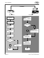
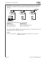
W&T
Quick installation
ETHERNET
P o w e r
Mo de Run
08:30
M e n ü :
Netzw er k
O K
F e h l e r
R S232
Port
A
R S2 32
P or t
B
W & T
W&T COM-Server
TCP/IP-Station
Site location
Sect.. 1.2
Entry in the "hosts" file
Box_IP
Box_Name
190.107.32.4 box 10
Connection of the
hardware Sect. 1.2._
COM-Server
with display ?
Setting the serial
parameters
Sect. 2.2.2 / Kap. 2.2.2.3
no
yes
Entry in the file "ethers"
Box_Etheraddr. Box_Name
Setting the IP address
Sect. 3.1
0:C0:3D:0:13:A5 box10
Setting the subnet mask
Sect. 3.2.1
Connection via
router/bridge ?
Test of network config.
ping box_name
yes
Test of serial config.
telnet box_name
(Output if all characters
to serial terminal device)
no
END
Page 32
Setting of gateway addr.
Sect. 3.2.1
END
Part 3: The TCP/IP protocol
W&T
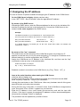
Assigning the IP address
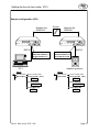
3.1 Assigning the IP address
You have a number of options available for assigning the IP address for the COM-Server.
On the COM- Server's display (display versions only)
In the "SET TCPIP - Box IP Number" enter the appropriate IP address.
By means of the RARP server
Activate the RARP server; enter the Ethernet address for the box in the /etc/ethers file
and the IP address for the box in the /etc/hosts file. Connect the COM-Server to the
network in the same segment of the RARP server.
Example:
The Ethernet number for your COM-Server is: 00:C0:3D:00:12:FF.
It is to be given the IP number 190.107.231.11 and the alias WT_1.
Entry in the file /etc/hosts:
190.107.231.11
WT_1
Entry in the file /etc/ethers:
00:C0:3D:00:12:FF
WT_1
If no RARP daemon is activated yet, do this now. Under SCO UNIX, for example, the
command is: rarpd -a
By means of the "arp" command
This method can only be carried out if the COM-Server does not yet have an IP
address, so that the entry is 0.0.0.0 (set at the factory). To change an IP address use a
different method, or remote configuration with TELNET.
Assign the COM-Server an IP address in the /etc/hosts file, and then use the "arp"
command to make an entry in the address table:
Under SCO UNIX, for example:
arp -s WT_1 00:C0:3D:00:12:FF
Establish a network connection to the COM-Server (e.g. Ping, Telnet ... WT_1).
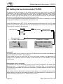
Input at the serial interface when starting the COM- Server
(versions without display only)
Connect a terminal to Port A and configure the serial port of the terminal with 9600
baud, no parity, 8 data bits, 1 stop bit, no handshake.
Activate the reset button on the COM-Server. After every hardware test all of the green
data LEDs light up for about two seconds.
During this time, key in the letter "x" at least 3 times. If the COM-Server recognizes the
input, the prompt "IPno.+<Enter>" appears on your terminal.
Enter the IP address in the usual format (xxx.xxx.xxx.xxx) and end the input with
<Enter>. If the input is correct, the assigned IP address is shown as acknowledgment;
otherwise the message "Failed" is displayed.
The procedure can be repeated any number of times.
Part 3: The TCP/IP protocol
Page 33
W&T
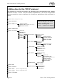
Menu tree for the TCP/IP protocol
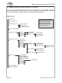
3.2 Menu tree for the TCP/IP protocol
The methods for controlling the system and adjusting the serial parameters were already
described in Parts 1 and 2. This part contains explanations of all of the configurations
which are needed in order to implement the client/server applications which are based on
TCP/IP.
Mode: RUN (Display menu only)
Mode: MONITOR
Mode: MENU TYP
Protocol TCPIP
Protocol IPX (Display menu only)
Box2Box TCP/IPX
Save the changes in non-volatile
memory with OK button (several
times, if necessary) until
"Saving..." appears on the display !
Mode: COM SETUP
Mode: SET TCPIP
Box IP No.
Subnet Mask
Gateway
Port A
)
( Port B
( Port C
)
( Port D
)
Socket Client
UDP Client
Server Socket:
Server IP:
Special
Inactiv. timeout
Connect. Timeout
Options
Disconnect Char
Client: "C"+Addr
Server Socket:
Server IP:
Special
Disconnect Char
Options
Client: "C"+Addr
Telnet Client
Server Port (23):
Server IP:
Disconnect Char
Inactiv.timeout
FTP Client
Server Port (21):
Server IP:
Special
Auto FTP
Options
FTP Client Login
(Remote configuration only)
Inactiv. timeout
Connect. Timeout
Protocol Char
Serial Protocol
Mode: INFO
Mode: Password
Mode: SAVE
(Remote configuration only)
System Options
SLIP / Net IP:
PPP / Net IP:
Network Delay
Flush Buffer
Telnet Echo
Mode: RESET (Remote configuration only)
Mode: FLASH/EEP
Page 34
Part 3: The TCP/IP protocol
Menu tree for the TCP/IP protocol
W&T
Whenever you leave this menu branch by pressing the OK key, the system stores the
parameters which have been set and attempts to work with them. You can return at any
time without saving by pressing the ← key.
When the message "Saving... " appears on the display, the new configuration has been
stored in non-volatile memory.
Remote configuration with Telnet
In addition, the COM-Server can be configured very conveniently via the network with the
help of TELNET. This can be done from any host which is connected to the network and
has the TELNET command available.
Simply enter the command
telnet [IP number or host] 1111
Please see your user manual for the precise syntax of the commands for your UNIX system
or your TCP/IP kernel. "1111" stands for the port number.
On the screen you will have almost exactly the same configuration menu as in the local
display. By entering the appropriate number you can select the sub-menus.
3.2.1 Mode: SET TCPIP
Box IP number
Enter the IP number here under which the box is to be addressed. Please note that this
number is not freely selectable, but must be defined dependent upon the network
address of the TCP/IP network. The form of input conforms to the usual syntax (e.g.
192.107.232.009). The cursor keys are used to input the numerical value. The ←/→
keys govern the position of the cursor within the number; the ↑/↓ keys can then be
used to count up or down by steps.
Sub-net mask
Specify the sub-net mask for the sub-network in which your COM-Server is located
(e.g. 255.255.255.0). Erroneous entries are corrected automatically when they are
saved.
Gateway
If appropriate, enter the IP number of the gateway, if routing to other sub-networks is
necessary.
3.2.1.1 Socket client
In this mode the COM-Server is activated as a TCP socket client (TCP streams). In the
"Server Socket" sub-menu enter the port number and in the "Server IP" sub-menu enter the
IP number of your socket server to which the COM-Server is to make a connection.
Part 3: The TCP/IP protocol
Page 35
Menu tree for the TCP/IP protocol
W&T
Special options
Inactivity timeout (default: 30 seconds):
Here you can enter a timeout for the connection. The value is specified in seconds in a
decimal number. If no data are transferred for the specified length of time, then the
COM-Server breaks off the connection to the socket server. The value zero deactivates
this mode.
Connection timeout (default: 300 seconds):
This value is also a connection timeout (decimal and in seconds). This timeout only
becomes active if there are no activities taking place on the network side between the
server and the client. This state indicates that the connection is hanging. The timeout
value should be chosen accordingly. The value zero deactivates this mode.
Disconnect char (default: 3):
Here you can enter a decimal character which will end the current connection. If this
character is received at the serial port, the COM-Server interrupts the connection to the
socket server. The character is not included in the transmission. The default value is 3,
which corresponds to the key code "Ctrl C." The value zero deactivates this mode.
Client: "C" + addr (default: inactive):
This function makes it possible to establish connections to different server addresses
without the need of adjusting settings on the Box (see Section 3.6.1.2).
3.2.1.2 UDP mode
In this mode the COM-Server is activated for the UDP mode; that is, data are transmitted
by means of UDP datagrams. Enter the port number in the "Server Socket" sub-menu, and
in the "Server IP" sub-menu enter the IP number of your UDP server with which the
COM-Server is to exchange data.
Special options
Disconnect char (default: 3):
The Disconnect char is only in effect when the option "Client: C+Addr" is active. If this
character is received at the serial port, the current destination address to the UDP
server is deleted. Data cannot be transmitted again until a new destination address is
sent. The character is not included in the transmission. The default value is 0.
Client: "C" + addr (default: inactive):
This function makes it possible to transfer data with various UDP servers, without the
need of adjusting settings on the Box (see Section 3.6.2).
Page 36
Part 3: The TCP/IP protocol
Menu tree for the TCP/IP protocol
W&T
3.2.1.3 Telnet client
In this menu the COM-Server is configured as a Telnet client. Enter the port number in the
"Server Port" sub-menu, and in the "Server IP" sub-menu enter the IP number of your
Telnet server to which the COM-Server is to establish the connection. The port number for
the standard Telnet server is 23.
Disconnect char (default: 3):
Here you can enter a decimal character which will end the Telnet connection. The
character is not included in the transmission. The default value is 3, which corresponds
to the key code "Ctrl C." The value zero deactivates this mode.
Inactivity timeout (default: 30 seconds):
Enter a
connection timeout here in seconds in a decimal number. If no data are transferred for
the specified length of time, then the COM-Server breaks off the connection to the
Telnet server. The value zero deactivates this mode.
3.2.1.4 FTP client
In this menu the COM-Server is configured as an FTP client. Enter the port number in the
"Server Port" sub-menu, and in the "Server IP" sub-menu enter the IP number of your FTP
server to which the COM-Server is to establish the connection. The port number for the
standard FTP server is 21.
Special options:
Auto FTP (default: inactive):
This switch toggles between serial protocol (inactive) and automatic operation (active).
See Section 3.4.2.1.
FTP client login (with Auto FTP = active)
(for remote configuration with TELNET only)
One after another enter the login parameters with which the COM-Server can lock into
your FTP server. The parameters needed are a username and password, the
transmission mode, and the name of the file which is to be read or written.
Inactivity timeout (default: 30 seconds):
Here you can enter a timeout for the connection. The value is specified in seconds in a
decimal number. If no data are transferred for the specified length of time, then the
COM-Server breaks off the connection to the socket server. The value zero deactivates
this mode.
Connection timeout (default: 300 seconds):
This value is also a connection timeout (decimal and in seconds). This timeout only
becomes active if there are no activities taking place on the network side between the
server and the client or if a continuous handshake stop is preventing the flow of data.
This state indicates that the connection is hanging. The timeout value should be
chosen accordingly. The value zero deactivates this mode.
Protocol char (default: 3):
If the FTP client is used with serial protocol, a decimal character must be entered here
which the protocol is to use as the separator character. This character must not occur
in the data stream, since this can lead to malfunctions or premature break-off of
transmission.
In the "Automatic FTP client" mode this character is evaluated as a condition for ending
the FTP connection, if it has a value other than zero.
Part 3: The TCP/IP protocol
Page 37
Menu tree for the TCP/IP protocol
W&T
3.2.1.5 Serial protocol
If the COM-Server port is to be locked as a SLIP or PPP router, enter the network address
of the sub-network here to which the SLIP of PPP packets are to be routed. Also see
Section 3.7.
3.2.1.6 System options
In this menu branch you can set certain specific values which are normally not meaningful.
Network Delay (default: active):
This switch changes the frequency with which serial data are packaged into network
packets. When the switch is "active": packaging starting from a number of characters
which depends upon the baud rate or after about 20 ms (lighter load on the network!);
with the switch "inactive": immediate packaging starting from the first character (for
applications whose timeouts do not allow this slight delay).
Telnet Echo (default: active):
If the COM-Server is operated as a TELNET server, the echo mode can generally be
set at the local terminal. If Remote Echo Mode is selected, the COM-Server gives an
echo for each character. If you have a serial terminal device which also sends an echo,
each character appears twice on the screen. For this purpose you can deactivate the
echo in the COM-Server.
Flush Buffer (default: active):
If this switch is "active," each time a new connection is established the serial buffer is
cleared, along with any residual data which were not able to be transmitted
(Handshake Stop). But if you connect a terminal device to the COM-Server, for which
the program for example requires a longer Handshake Stop, you can prevent clearing
of the buffer by deactivating this switch. This makes it possible to establish a number of
connections in a row on the network, and the data are collected in the buffer until they
are transmitted.
3.2.2 Mode: RESET
(Only with remote configuration via TELNET)
Select this menu item to execute a software reset on the COM-Server. First your Telnet
session will be closed normally.
3.2.3 Mode: SAVE
(Only with remote configuration via TELNET)
Here you can make all of the changes which you have made in the Box take effect. If a
password has been activated, then it is demanded here. If the input is correct, the message
"Saving...." appears on the screen.
If the input is incorrect, you are returned to the main menu without saving the values and
the message "Failed" appears on the screen..
Page 38
Part 3: The TCP/IP protocol
Menu tree for the TCP/IP protocol
W&T
3.2.4 Mode: MONITOR
This mode permits constant monitoring of the connection status of all COM-Server ports.
By scrolling the screen of the display upward or downward you can read the status of each
channel, one at a time.
In TELNET remote configuration mode you select the port by entering the corresponding
number. This gives you the current status of the connection. The output is updated when
you leave the sub-menu and then return to it again.
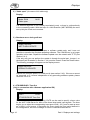
Status monitor for port A:
Port A is locked as an FTP client; the connection
to the FTP server (port 21) is not active
A: FTP client
00021 Unlock
Connection status: Client/Server mode
Locked:
The connection is set up correctly.
Scanng:
The Box is looking for its partner box or station.
Disconn:
The connection attempt was refused by the partner
station
Unlock:
The Box is locked by the designated port or socket,
but does not have an active connection
Remote server port: (decimal)
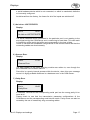
Status monitor for port B:
Port A is working in Standard Server mode and was
locked by the client with the port number 2251 of the
station with the IP number 190.107.231.101
B: IN USE 02251
190.107.231.101
Connection status: Standard Server mode
FREE:
The port is free.
IN USE:
The port has an active connection.
Part 3: The TCP/IP protocol
Page 39
W&T
Data transfer by FTP
3.3 Protocols for the TCP/IP suite
The following protocols and applications are implemented in the COM-Server:
ARP, RARP, ICMP (PING functions),
FTP (client and server), TELNET (client and server),
TCP and UDP sockets (for client/server applications),
SLIP,
RIP (active in configured SLIP mode)
3.4 Data transfer via FTP
Data exchange by means of FTP protocol is file oriented, that is, it is possible to output file
contents to the serial port of the COM-Server, or to read characters into files from the serial
port. The COM-Server includes both an FTP server and an FTP client.
3.4.1 Mode: FTP server
This mode should be used when the data to be transferred are present in file form and the
action is always to be started from your PC or UNIX host.
No preliminary settings are needed on the COM-Server for this mode. You can address the
device by name or IP address, like any other station on the network.
Selecting the serial port:
The serial port is selected by designating a port number when calling FTP. If no port is
designated, port A is addressed by default.
Calling FTP:
ftp
ftp
ftp
ftp
ftp
IP number or host
IP number or host
IP number or host
IP number or host
IP number or host
7000
7100
7200
7300
- addresses port A
- addresses port A
- addresses port B
- addresses port C
- addresses port D
After inputting the command "ftp" you can acknowledge the request for the login name with
"ENTER".
The following commands are available:
put [local file remote file]
- send the file "local file" to the RS232
get [remote file local file]
- read in characters from the RS232 into the local file
ascii
- transfer ASCII files
image
- transfer binary files
quit
- ends the FTP session
Comments on [remote file]:
put
- enter any letter, since no remote file exists
get
Page 40
- 1. likewise enter any name or letter or
- 2. code a time criterion for halting the transfer of data
For this purpose enter a number of no more than 3 digits (one tick corresponds
to one second). If [remote file] has no value in this range, the connection is
broken off 30 seconds after the last character is read in.
Part 3: The TCP/IP protocol
Data transfer by FTP
W&T
For the exact designations of your function calls please consult the user manual for your
FTP software.
Important:
In the menu "Mode: MONITOR" the entry "FREE" must be visible on the corresponding
screen before a connection can be opened.
3.4.2 Mode: FTP client
This mode makes it possible to access files on any PC or UNIX host which has an FTP
server active. The action must always be initiated from the serial terminal device.
The COM-Server port is configured for this mode in the "SET TCPIP - Port ... - FTP Client"
menu.
Settings:
Menu: SET TCPIP - Port ... - FTP Client - Server Port(21): 21 for the standard FTP
Server or a different port number for a special FTP server.
Menu: SET TCPIP - Port ... - FTP Client - Server IP:" IP number of the station on
which the FTP server is to be called.
After all of the values have been fed into the COM-Server and confirmed repeatedly with
OK until the message "Saving" appears on the display, the client mode is activated. "FTP
Client" appears in the first line of the status monitor.
FTP client functions:
TYPE A
Activation of the ASCII transmission type
TYPE I
Activation of the IMAGE (binary) transmission type
STOR remote file: Stores all of the data received at the serial port in remote file
RETR remote file: Outputs "remote file" to the serial port
APPE remote file: Appends all data received at the serial port to the end of remote file
LIST remote dir: Outputs remote dir
Please pay attention to the CAPITALIZATION of the commands!
For transmission of the necessary parameters (login, password, FTP client functions) there
are two options, as described in the following section.
Part 3: The TCP/IP protocol
Page 41
W&T
Data transfer by FTP
3.4.2.1 Automatic FTP client
This mode is appropriate whenever the same command is to be executed repeatedly,
dependent upon the presence of data at the serial port.
Activation:
Set the switch "SET TCPIP - Port ... - FTP Client - Special Options - Automatic FTP" on the
COM-Server to "active." Call the remote configuration from a TCP/IP station (telnet IP no.
1111) and choose
"SET TCPIP - Port ... - FTP Client - Special Options - FTP Client Login".
Enter, one after the other, the login name, the password and the FTP client functions.
Important!
You have a maximum of 80 characters available for all specifications!
Establishing a connection:
The FTP client functions LIST and RETR are invoked by the presence of any character at
the serial port. This character is not transmitted.
The FTP client functions STOR and APPE are executed as soon as the first character to be
transmitted is present at the serial port.
As the end conditions for the FTP client functions STOR and APPE, please enter at least
one of the following values on the COM-Server or by means of remote configuration:
"SET TCPIP - Port ... - FTP Client - Special Options - Inactive Timeout" (in seconds)
For example:
Inactive Timeout = 00030 -> If 30 seconds pass without it being possible to read a character
from the RS232 port, the connection is broken off ("0" corresponds to no time limit, but most
servers do not allow a connection longer than 5 minutes).
"SET TCPIP - Port... - FTP Client - Special Options - Protocol Char"
If this character is received the connection is closed immediately. The character is not
transmitted! If the value of the character is zero, this end condition is disabled.
The first 16 characters of any error codes from the FTP server are output to the display.
Page 42
Part 3: The TCP/IP protocol
Data transfer by FTP
W&T
3.4.2.2 FTP client with serial protocol
This mode is appropriate when you want to execute constantly changing commands with
different files and have access to a means of terminal input or of programming on the serial
side.
Activation:
Set the switch "SET TCPIP - Port ... - FTP Client - Special Options - Automatic FTP" on the
COM-Server to "Inactive".
Select a character which does not occur in your stream of useful data and enter it under
"SET TCPIP - Port ... - FTP Client - Special Options - Protocol Char" (for example, "003"
corresponds to the keycode "Ctrl C").
Serial protocol:
The format of the login string (entered via the serial port) is:
login_name< lf >password< lf >(TYPE I | TYPE A)< lf >(STOR | RETR | APPE | LIST)
remote file/dir < lf >disconnect char
The individual commands are separated with "0A hex" (corresponding to "line feed,"
keyboard input "CTRL J").
Important!
For the complete login string you have 128 characters available!
Establishing a connection:
Send the login string to the appropriate port of the COM-Server. If the string is received
completely, the COM-Server begins to set up the connection and process the commands.
If the functions are successfully executed in sequence, you receive the code "OK+
disconnect char".
Afterward the useful data are transmitted, from the serial port to the network or vice versa,
depending on the command. The stream of useful data must also be concluded with
disconnect char.
If an error occurs, the error code of the FTP server + disconnect char is reported.
In both cases the connection is closed automatically and you receive the ending code of
the FTP server + disconnect char.
Omitting the "TYPE" command:
It is possible to omit parameter 3 (the TYPE command) and enter only the separator character
"Ctrl J". In that case the string would look like this:
login_name<lf>password<lf><lf>(STOR|RETR|APPE|LIST) remote file/dir<lf>disconnect char
Part 3: The TCP/IP protocol
Page 43
W&T
Data transfer by FTP
Examples:
1.) User "elton" with the password "happy" would like to obtain the file "/etc/hosts" in ASCII
format. The value "003" (Crtl C) is entered as the protocol character. The protocol would look
like this:
Serial device:
elton<lf>happy<lf>TYPE A<lf>RETR /etc/hosts<lf><Ctrl C>
COM-Server:
OK<Ctrl C>
[content of the file /etc/hosts]<Ctrl C>
221 Goodbye<Ctrl C>
2.) User "elton" with the password "happy" would like to append binary data to the end of the
file "/usr/elton/config". The value "003" (Crtl C) is entered as the protocol character. The
protocol would look like this:
Serial device:
COM-Server:
Serial device:
COM-Server:
elton<lf>happy<lf>TYPE I<lf>APPE /usr/elton/config<lf><Ctrl C>
OK<Ctrl C>
[binary data]<Ctrl C>
221 Goodbye<Ctrl C>
3.) User "elton" with the password "happy" would like to look at the file "/usr/private" and
transfer the data in ASCII mode, but the file is not present. The protocol would look like this:
Serial device:
COM-Server:
elton<lf>happy<lf>TYPE A<lf>RETR /usr/private<lf><Ctrl C>
550 /usr/private: No such file or directory<Ctrl C>
221 Goodbye<Ctrl C>
Connection monitor:
In the corresponding status "MONITOR" you can read out the current status of the
connection (see Section 2.3).
3.4.2.3 Deactivating the "FTP client mode":
Set the value in the menu "SET TCPIP - Port... - FTP Client - Server Port" to zero. The
COM-Server deactivates the connection and deletes the FTP client mode.
Page 44
Part 3: The TCP/IP protocol
W&T
Data transfer by TELNET
3.5 Data transfer via TELNET
Telnet is a protocol for terminal emulation, with character-oriented data transfer. Telnet
makes active, bidirectional character exchange possible between the UNIX station or the
PC and the serial terminal device connected to the COM-Server.
3.5.1 Mode: TELNET server
No default settings are required on the COM-Server. You can address the device like any
other station on the network, by name or IP address.
Selecting the serial ports:
The serial ports are selected by designating a port number when calling FTP. If no port
number is designated, port A is addressed by default.
Calling Telnet:
telnet
telnet
telnet
telnet
telnet
IP number or Host
IP number or Host
IP number or Host
IP number or Host
IP number or Host
6000
6100
6200
6300
- addresses port A
- addresses port A
- addresses port B
- addresses port C
- addresses port D
If the connection is successful, a message from the TELNET server appears on the screen.
From this point on data can be read in or output in character form via the keyboard.
All data which are present at the serial port are output to the screen (and, if so specified, to
a file). All keyboard entries are sent as data in character form to the serial port.
From the moment the connection is established, the host works in "local echo mode,"
though it is also possible to switch over to "remote echo mode."
Important:
The entry "FREE" must be visible on the status monitor for the port before a connection can
be made.
3.5.2 Mode: TELNET client
This mode makes it very simple to implement a terminal emulation on a serial device and
use it to establish direct communication with the TCP/IP station on which the Telnet server
is active.
The COM-Server port is configured for this mode in the "SET TCPIP - Port ... - Telnet
Client" menu.
Settings:
Menu: SET TCPIP - Port ... - Telnet Client - Server Port (23): 23 for the standard
Telnet server or a different port number for a special Telnet server
Menu: SET TCPIP - Port ... - Telnet Client - Server IP: IP number of the host on which
the Telnet server is to be called.
Part 3: The TCP/IP protocol
Page 45
Data transfer by TCP/IP sockets
W&T
After you have entered and stored all of the values, the Telnet client mode is activated.
The message "Telnet client" appears in the status monitor for the port.
Opening and closing the connection to the Telnet server:
The connection is opened when the first character is read in from the serial port. You can
close the connection with a special character, which can be input in the "SET TCPIP - Port
... - Telnet Client - Disconnect Char: " menu. It is important that this value must not be used
within a Telnet session, since this would lead to premature termination. The default value is
"003," which corresponds to the keyboard code "Ctrl C".
In the "MONITOR" you can read the status of the connection; the message "Locked" or
"Unlock" appears there, depending upon whether the connection is active or not (also see
Section 2.3).
Deactivating the "Telnet client mode":
Set the value to zero in the "SET TCPIP - Port ... - Telnet Client - Server Port:" menu. The
COM-Server breaks off the connection and deactivates the Telnet client mode.
3.6 Data transfer by TCP/IP sockets
With the socket API (such as "WINDOWS socket API," "UNIX socket interface," ...) it is
possible to implement a great variety of application cases in the form of "client" or "server"
processes on TCP/IP stations. The API offers the entire set of functions for transporting the
data over the network. You can construct your own application, that is, the further
processing and evaluation of the data, in accordance with the requirements (for the
extended functions of the COM-Server also read Part 6, "Expanded TCP/IP socket
functions" and Section 6.6 "Instructions for socket programming").
The COM-Server offers two options at this level: client/server processes with TCP sockets
(streams) and with UDP sockets (datagrams).
The TCP protocol is connection oriented; that is, during the transfer of data there is a fixed
connection between client and server. TCP has all of the mechanisms for opening and
closing a connection and ensuring error-free data transfer over the network.
In contrast to this, UDP has no mechanisms for repeating data packets or checking their
completeness. Data transfer with UDP is recommended, when a higher-level protocol
between the serial terminal device on the COM-Server and the application on the TCP/IP
station already ensures error-free transfer of data.
Page 46
Part 3: The TCP/IP protocol
Data transfer by TCP/IP sockets
W&T
3.6.1 Applications with TCP sockets
The server and client processes in the COM-Server have the following TCP sockets:
"8000" - port A
"8100" - port B
"8200" - port C
"8300" - port D
Do not use these four socket numbers for your own processes!
3.6.1.1 COM-Server mode: socket server
In this mode no settings are needed on the COM-Server.
Important:
The entry "FREE" must be visible in the status MONITOR for the corresponding port!
The connection is controlled by your client process; that is, you open and close the
connection. Once a connection has been established, bidirectional data traffic is possible
between the two processes. The COM-Server delivers all of the data from the LAN to the
serial port, and conversely reads in all data from the serial port, in order to convey it to your
client process.
3.6.1.2 COM-Server mode: socket client
In this mode the COM-Server itself, as a client, is able to open and close a connection,
depending upon whether data are to be transferred or not. If there is no connection to the
server active at the moment, it can also itself be the server and accept connections.
The mode is configured in the "SET TCPIP - Port ... - Socket Client" menu for always
connecting to the main server, or in the "SET TCPIP - Port... - Socket Client - Special
Options - Client: "C"+Addr."" menu for connections with various servers.
Settings:
Menu "SET TCPIP - Port ... - Socket Client - Server Socket:"
The socket on which the server program is working on the host.
Menu "SET TCPIP - Port ... - Socket Client - Server IP:"
The IP number of the host on which the server program is active.
Menu "SET TCPIP - Port ... - Socket Client - Special Options - Inactivity Timeout:"
Here is the place to configure the timer whose count-down causes the Box to close the
connection. The timer is reset when data are exchanged.
tick = 1 second
"00001" is the minimum value (1 second).
"00000" deactivates the function.
Menu "SET TCPIP - Port... - Socket Client - Special Options - Client: "C"+Addr.":
Activating this switch makes the socket client mode active. The format for the address
input is: "C-key+address+CR/LF".
Part 3: The TCP/IP protocol
Page 47
W&T
Data transfer by TCP/IP sockets
Examples:
C190.107.231.101,4800<CR>
(if there is no entry for a server socket under "...- Socket Client-")
C101<CR>
(if there is an entry for a server socket under "...-Socket Client-," for example 190.107.231.
and the port no. 4800 are then the defaults).
After all of the values have been saved on the COM-Server and all of the queries have
been acknowledged with "OK" until the message "Saving" appears on the screen, the client
mode is activated. The entry "Client: Socket" appears on the status monitor of the
corresponding port. The current status of the connection can always be read here.
Important:
Please note the explanations for the "Socket Client" menu in Section 3.2.1.1. There are a
number of options for opening and closing the connection, depending upon various events
("Special Options" sub-menu).
Deactivating the "socket client mode":
Set the value to zero in the "SET TCPIP - Port ... - Socket Client - Server Socket:" menu, or
deactivate the "Client: "C"+Addr." switch in the "SET TCPIP - Port... - Socket Client Special Options" menu. The COM-Server breaks off the connection and deactivates the
socket client mode.
Page 48
Part 3: The TCP/IP protocol
W&T
Data transfer by TCP/IP sockets
3.6.1.3 Client/server mode between COM-Servers
There are various options for connecting two or more COM-Servers with each other by
means of this mode. Use the server socket addresses 8000 (port A), 8100 (port B), 8200
(port C) or 8300 (port D). The COM-Servers can then establish mutual connections when
data are present at the serial port, and can close the connections again.
"C key addressing" makes varying connections between COM-Servers possible.
Important:
In contrast to the Box-to-Box mode these are non-durable connections and are not limited
to two COM-Server ports at a time.
Application: A control program polls a measuring device; the measuring device is
passive.
A
Configuration menu
"SET TCPIP - Port ... - Socket Client"
08: 30
P o w er
Menü:
Mode Run
Netzwerk
08: 30
O K
F eh l e r
R S 2 32 P o r t A
COM-Server A
Server Socket: 8000
Server IP: IP-Addr. COM-Server B
Client "C+Addr": inactive
B
ETHERNET
P o w er
Mode Run
Menü:
Netzwerk
O K
F eh l e r
R S 2 32 P o r t B
R S 2 32 P o r t A
W &T
R S 2 32 P o r t B
W &T
Serial port
Serial port
COM-Server B
Server Socket: 0000
Server IP: IP-Addr. 0.0.0.0
Client "C+Addr": deaktiv
Serial connection
Application: A control program polls a measuring device; the measuring device can
convey data actively to the control program.
A
Configuration menu
"SET TCPIP - Port ... - Socket Client"
Mode Run
08: 30
P o w er
Menü:
Mode Run
Netzwerk
O K
F eh l e r
R S 2 32 P o r t A
COM-Server A
Server Socket: 8000
Server IP: IP-Addr. COM-Server B
Client "C+Addr": inactive
B
ETHERNET
P o w er
W &T
Serial port
08: 30
Menü:
Netzwerk
O K
F eh l e r
R S 2 32 P o r t B
R S 2 32 P o r t A
R S 2 32 P o r t B
W &T
Serial port
COM-Server B
Server Socket: 8000
Server IP: IP-Addr.COM-Server A
Client "C+Addr": inactive
Serial connection
Part 3: The TCP/IP protocol
Page 49
W&T
Data transfer by TCP/IP sockets
Application: A control program polls a number of measuring devices; the measuring
devices can send data to the control program independently (in case of an error, for
example).
.......
A
B
P o w er
Mode Run
08: 30
P o w er
Menü:
Mode Run
Netzwerk
O K
F eh l e r
R S 2 32 P o r t A
08: 30
P o w er
Menü:
Mode Run
Netzwerk
O K
F eh l e r
R S 2 32 P o r t B
W &T
R S 2 32 P o r t A
08: 30
Menü:
Netzwerk
O K
F eh l e r
R S 2 32 P o r t B
W &T
Serial port
ETHERNET
....
C
R S 2 32 P o r t A
R S 2 32 P o r t B
W &T
Serial port
Serial port
Configuration menu "SET TCPIP - Port .. - Socket Client"
COM-Server A
Server Socket: 0000
Server IP: IP-Addr. 0.0.0.0
Client "C+Addr": inactive
COM-Server B, C, ...
Server Socket: 8000
Server IP: IP-Addr. COM-Server A
Client "C+Addr": inactive
The control program addresses the measuring devices via the serial port in the
following format: C ip_addr, port_number
Example:
C190.107.231.8,8000<CR>
Page 50
Establishes a connection with COM-Server port A, using the IP
address 190.107.231.8
Part 3: The TCP/IP protocol
Data transfer by TCP/IP sockets
W&T
3.6.2 Applications with UDP sockets (Revision 3.7 and later)
The server and client processes in the COM-Server have the following UDP sockets:
"8500" - port A
"8600" - port B
"8700" - port C
"8800" - port D
3.6.2.1 COM-Server mode: UDP mode
In each case (client or server) the respective port on the COM-Server must be configured
for transport with UDP sockets, in order to guarantee clear assignment of the incoming
serial data. In principle, all UDP datagrams which are addressed to the respective port are
accepted. Incoming serial data are sent to the configured application (server IP, server
socket).
The mode is configured in the "SET TCPIP - Port ... - UDP Mode" menu for always
connecting to the same TCP/IP station (and it makes no difference which is the client and
which the server, since there is no setting up and breaking off of a connection) or else in
the "SET TCPIP - Port... - UDP Mode - Special Options - Client: "C"+Addr."" menu for
connections with changing servers.
Settings:
Menu "SET TCPIP - Port ... - UDP Mode - Server Socket:"
Socket at which the server or client program is working on the host
Menu "SET TCPIP - Port ... - UDP Mode - Server IP:"
IP number of the host on which the server or client program is activated
Menu "SET TCPIP - Port... - UDP Mode - Special Options - Client: "C"+Addr."
Activation of the switch activates a "UDP client" mode. The server is addressed in
serial order, i.e. the useful data must be preceded by the destination address. This
address is not included in the transmission. It remains in effect until the "disconnect
char" (configurable under Special Setup) is received.
Format of the address input: "C address CR/LF".
Examples:
address = IP address,socket (if there is no server socket entered under "... - UDP Mode - ")
C190.107.231.101,4800<CR>
address = 4th byte of the IP address (if entered under "... - UDP Mode - Remote Server IP " and " Remote Server Socket" , e.g. 190.107.231.___ and port no. 4800 are then the defaults)
C101<CR>
After all of the values have been saved on the COM-Server and all of the queries have
been acknowledged with "OK" until the message "Saving" appears on the screen, the client
mode is activated. The entry "UDP mode" appears on the status monitor of the
corresponding port. The current status of the connection can always be read here.
Deactivating the "UDP mode":
Set the value to zero in the "SET TCPIP - Port ... - UDP Mode - Server Socket:" menu, or
deactivate the "Client: "C"+Addr." switch in the "SET TCPIP - Port... - UDP Mode - Special
Options" menu.
Part 3: The TCP/IP protocol
Page 51
W&T
SLIP or PPP mode
3.7 SLIP mode
The W&T COM-Server can also be used as a simple router. The IP datagrams are
transported via the serial medium using the SLIP or PPP protocol.
Ethernet (IP)
RS232 (SLIP)
Subnet Mask
255.255.255.0
Box-IP-number
190.010.010.004
190.10.10.1
BNC/AUI/RJ45
W&T
ComServer
#58xxx
RS232
NetIP A:
190.010.020.000
190.10.20.5
NetIP B:
190.010.021.000
RS232
190.10.21.6
190.10.10.2
Packet framework:
Ethernet IP-datagramm
SLIP/PPP
IP-datagramm
Konfiguration eines COM-Servers im SLIP/PPP-Modus
SLIP settings:
In the menu "SET TCPIP - Port ... - Serial Protocol - SLIP / NetIP:" enter the network IP
number of the sub-network to and from which the data is to be routed, and confirm with the
OK button. The COM-Server forwards all of the packets with the same network address via
the serial port and reads in all of the packets from the RS232 port in order to distribute
them on the LAN.
Page 52
Part 3: The TCP/IP protocol
Notes
W&T
Part 3: The TCP/IP protocol
Page 53
Notes
Page 54
W&T
Part 3: The TCP/IP protocol
W&T
Part 4
The IPX protocol
Mode: SET IPX
Mode: INFO
Mode: MONITOR
Part 4: The IPX protocol
Page 55
W&T
Menu tree for the IPX protocol
4.1 Menu tree for the IPX protocol
This chapter is only relevant for those who have obtained the Netware Development Kit
(Product no. #58113) for the COM-Server. To operate the COM-Server in the IPX Box to
Box mode, please read Part 5 (Box to Box TCP/IPX).
Operation and setting the serial parameters were described in Parts 1 and 2; this part
explains very briefly how to configure the COM-Server so that you can address it from your
PC using your own application software.
Mode: RUN
Mode: MONITOR
Mode: MENU TYP
Save the changes in non-volatile
memory with OK button (several
times, if necessary) until
"Saving..." appears on the display !
Protocol TCPIP
Protocol IPX
Box2Box TCP/IPX
Mode: COM SETUP
Mode: SET IPX
Mode: INFO
Port A
( Port B
( Port C
( Port D
Port Number
.... )
.... )
.... )
Node Number
Network Number
SOFTW Date/Rev:
BOOT BLOCK Rev.
Port A
( Port B
.... )
( Port C
.... )
( Port D
.... )
Port A
COM Setting
Callback Address
Callback Network
Mode: Password
Mode: FLASH/EEP
Important!
Whenever you leave the menu branches by way of the OK button, this always leads to a
save of the changes that have been made and the attempt to work with them. The ←
button can be used to return without saving.
The COM-Server can also be configured via the network with the help of the supplied
driver. If you have more than one COM-Server connected to your network, configuration via
the network is preferable, since the driver lists all of the devices in one file and configures
them automatically. Please read the applicable instructions.
Page 56
Part 4: The IPX protocol
Menu tree for the IPX protocol
W&T
4.1.1 Mode: SET IPX
Configuration of the COM-Server for the network is accomplished with a single entry for
each port present.
Port number
Assign a port number in decimal format to each port. This port number is used for
unambiguous identification of the particular serial terminal device being addressed. At
the factory the value 65535 is entered for all ports. This value stands for the initial
entry, and must be changed. A change can be made by overwriting the former values,
followed by confirmation with the OK button.
Important!
Please be sure to note that a port number can only occur once on a network. The
values 0 and 65535 are not allowed.
The numerical value is input with the cursor keys. The ←/→ keys govern the cursor
position within the number, which can then be counted up or down in steps by means of the
↑/↓ keys.
4.1.2 Mode: INFO
Network number
Returns the number of the network to which the COM-Server is connected. If there is
no Netware server on the network, the entry remains empty.
Callback ethernet adr.
Designates the ethernet address of a controller PC or the port number of a
COM-Server, with which a connection is made automatically as soon as serial data are
received (if no other connection exists).
More detailed explanations of this may be found in the chapter on installation of the rerouter via
Interrupt 14 (Instructions for "Netware Development Kit").
Callback network no.
Designates the address of the network where there is a controller PC or a COM-Server
with which a connection can be made automatically as soon as serial data are received
(if there is no other connection).
More detailed explanations of this may be found in the chapter on installation of the rerouter via
Interrupt 14 (Instructions for "Netware Development Kit").
Part 4: The IPX protocol
Page 57
W&T
Menu tree for the IPX protocol
4.1.3 Mode: MONITOR
This mode permits constant monitoring of the connection status of all COM-Server ports.
The data in the display are updated immediately whenever there is a change.
Page 58
A: FREE
Port A has no active network connection
A: IN USE 7001
000000C2
Port A has an active network connection
The partner station is in the network at
the address 000000C2
The IPX socket of the partner station
has the number 7001hex
Part 4: The IPX protocol
W&T
Part 5
Box to box TCP / IPX
Menu tree for box to box TCP / IPX
Box to box operation
Box to box IPX
Box to box TCP
Bus master/slave operation
Part 5: Box to box TCP / IPX
Page 59
W&T
Menu tree for box to box TCP / IPX
5.1 Menu tree for box to box TCP/IPX
This menu tree can be used to make all of the settings which are needed in order to
"connect" multiple COM-Servers with each other. As always, you still have the usual serial
connections available, but data transfer is now handled via the network.
Display menu:
Mode: RUN
Save the actual configuration
to non volatile memory by
pressing the "OK" button
until the COM-Server shows
"Saving" in its display.
Mode: MONITOR
Mode: MENU TYP
Protocol TCPIP
Protocol IPX
Box2Box TCP/IPX
Mode: COM SETUP
Mode: SET IPX
Mode: SET TCPIP
Port A
( Port B
( Port C
( Port D
)
)
)
Box IP No.
Subnet Mask
Gateway
Port A
)
( Port B
( Port C
)
( Port D
)
Port Number
Box to Box
IPX
Box to Box
TCPIP
IP Bus Mode
Slave Port-No.:
Slave Network
Slave Ether-No.:
Slave Box Port:
Slave Box IP:
Special Options
Slave: Master IP
Master: Subnet IP
System Options
Mode: INFO
Node Number
Network Number
SOFTW Date/Rev:
BOOT BLOCK Rev:
Port A
)
( Port B
( Port C
)
( Port D
)
Dispatch String1
Dispatch String2
Network Delay
COM Setting
Mode: Password
Mode: FLASH/EEP
Page 60
Part 5: Box to box TCP / IPX
W&T
Menu tree for box to box TCP / IPX
Leaving the menu branch by pressing the OK key always causes the system to save the
parameter settings and to attempt to work with them. It is always possible to return without
saving by pressing the ← key.
If the message "Saving... " appears on the display screen, the new configuration has been
received into nonvolatile memory.
Remote configuration with Telnet
If you wish to connect the COM-Server with the network protocol TCP/IP (box to box
TCPIP) or IP (IP bus mode), you can also perform the configuration of the devices very
easily over the network, using TELNET. This can be sent from any host which is connected
to the network and has the TELNET command.
Simply enter the command
telnet [IP number or host] 1111
Please look up the exact syntax of the commands for your UNIX system or your TCPIP
kernel in your user's manual. "1111" is used for the port number.
The following configuration menu appears on the screen. You can select the submenus by
entering the corresponding number.
Mode: MONITOR
Mode: MENU TYP
Protocol TCPIP
Box2Box TCP/IPX
Mode: COM SETUP
Mode: SET TCPIP
Box IP No.
Subnet Mask
Gateway
Port A
)
( Port B
( Port C
)
( Port D
)
Box to Box
TCPIP
IP Bus Mode
System Options
Mode: INFO
Save the actual configuration
to non volatile memory by
pressing the "OK" button
until the COM-Server shows
"Saving" in its display.
Slave Box Port:
Slave Box IP:
Special Options
Dispatch String1
Dispatch String2
Slave: Master IP
Master: Subnet IP
Network Delay
Node number
SOFTW Date/Rev:
BOOT BLOCK Rev:
COM Setting
Port A
)
( Port B
( Port C
)
( Port D
)
Mode: Password
Mode: SAVE
Mode: RESET
Mode: FLASH/EEP
Part 5: Box to box TCP / IPX
Page 61
W&T
Menu tree for box to box TCP / IPX
5.1.1 SET IPX mode
Port number
Assign a port number in decimal format to each port. This port number is used for positive
identification of the serial device which is being addressed. The factory default setting for both
ports is 65535. This value stands for the initial entry, and must be changed. Changes can be
made by overwriting the former values and confirming with the OK key.
Important!
Be sure to remember that a particular port number can only be assigned once in each
network. The values 0 and 65535 are not allowed.
Box to box ( IPX )
This submenu is used to configure the master box for the box to box mode. Enter the
decimal port number of the desired port of the slave box under the item "Slave Port
No.:". After you leave the menu by pressing the OK key, and after each restart, the
COM-Server automatically searches the network for the specified port and blocks it
from access by other users. In the event of power loss, network interruption etc., after
the problem has been corrected the system automatically attempts to re-establish the
connection.
The entry "Slave Port No." = 0 terminates the connection, freeing the port for a new
connection.
If the other station is on a different network, under "Slave network" enter the network
address of the slave box. The value 0 causes the COM-Server to search for the
designated partner station only on the local network.
If it is necessary to prevent broadcasts at the lowest level when routing into other
networks (when routing over an ISDN line, for example), enter the last two digits of the
six-digit Ethernet address for the slave box under "Slave Ether No." (for example: 12
A7).
Important!
The box to box mode is set exclusively on a COM-Server; that is, for this mode of operation
the slave port may only be set on a COM-Server. No changes or entries are needed at the
partner station (see also Section 5.2, "Box to box operation").
5.1.2 SET TCPIP mode
The basic configuration of the COM-Server for working with the TCPIP protocol was
already explained in detail in sections 3.1 and 3.2. If you have not yet configured the
COM-Server for your network (IP number, subnet mask, gateway), please read the
indicated sections first.
Box to box TCPIP
Configure the master box for the box to box mode here. In the submenu "Box to box
TCPIP" enter the desired port (Port A-D) under the item "Slave Box Port" and the IP
number of the slave box under the item "Slave Box IP." If you select the entry "-" under
"Slave Box Port," the port is free.
Page 62
Part 5: Box to box TCP / IPX
Menu tree for box to box TCP / IPX
W&T
Important!
The box to box mode is set exclusively on one COM-Server; that is, for this operating
mode the "slave box port" may be set only on the master box. No changes or entries are
needed on the slave box itself (see also Section 5.2, "Box to box operation").
Bus master/slave mode
If you have connected several COM-Servers in a network with the intention that they
constitute a bus, then configure each port here individually (see Section 5.5).
5.1.3 MONITOR mode
This mode permits constant monitoring of the connection states of all COM-Server ports.
The information on the display screen is updated immediately whenever there is a change.
In the status query during remote configuration with TELNET (TCPIP protocol only),
updating is accomplished by leaving and again calling the monitor for the port in question.
A: B2B Master
"B" - Scanning
TCPIP Port A communicates as master
with Port B of the corresponding box.
Connecting state
Locked: The port is locked by the specified remote port
Scanng: The COM server is searching the corresponding box
Disconn: The access was denied by the remote box
Unlock: The box is locked by the specified port, but loses
the connection to the remote box (i.e.by power loss)
FREE: The port is not in use.
Remote Port: TCPIP: Port name (A .. D)
IPX:
Port number
5.1.4 RESET mode
(For remote configuration with TELNET only)
Select this menu item to perform a software reset on the COM-Server. First your Telnet
session will be closed normally.
5.1.5 SAVE mode
(For remote configuration with TELNET only)
You can use this to make all of the changes which you have made in the box take effect. If
a password has been activated, then it is asked for here. If the input is correct, then the
message "Saving..." appears on the screen.
If the input is incorrect the values are not saved and you are returned to the main menu;
the message "Failed" appears on the screen.
Part 5: Box to box TCP / IPX
Page 63
W&T
Box to box operation
5.2 Box to box operation
The box to box mode allows a firm logical connection of any two COM-Server ports over
the network, without an additional controlling computer. In this mode the two connected
serial devices are in constant online contact with each other. Any additional data traffic or
other network protocols have no effect on the connection.
ETHERNET
Power
Mode Run
08:30
Power
M en ü :
Mode Run
N et z wer k
08:30
M en ü :
N et z wer k
O K
F ehler
O K
F ehler
RS2 32 Por t A
RS2 32 Por t A
RS2 32 Por t B
RS2 32 Por t B
W &T
W &T
serial port
serial port
Serial communication A
PC 1
Measuring device
Typical applications
Replaces costly serial star cabling layouts, for example in medium-size computing
systems.
Serial connections over greater distances. A pair of COM-Servers replaces two line
drivers, and in addition offers error correction through the Ethernet transmission
procedure.
Long-distance serial connection using already existing Ethernet internetwork
connections (routers, bridges etc.).
Implementation of serial connections at frequently changing locations without the
expense of additional cabling. Simply connect to the Ethernet cable.
Page 64
Part 5: Box to box TCP / IPX
W&T
Setting the box to box mode ( IPX )
5.3 Setting the box to box mode (IPX)
All of the settings are made locally on one W&T COM-Server. The port at which the box to
box mode is initialized functions as the master port. After every reset it will automatically try
to find the defined partner station on the network, and when successful will block it from
access by other users. This port then functions as the slave port
In the COM-Server menu SET IPX, set the desired port of the other station under the Box
to box (IPX) / Slave Port No. for the appropriate port. If you wish to communicate with a
measuring device which is connected to COM-Server port no. 11, for example, enter the
value "11" under Slave Port No.
Port A
Port No.
SET IPX
Mode: SET IPX
Port A
Port B
Port C
Port D
....
....
....
Enter number (dec)
Box to Box (IPX)
Slave Port No. (dec.)
Slave Network
Slave Ether No.
00000
position = key ←/→
value = key ↑/↓
Port no. of corresponding box
(00000 = no Box-to-Box mode)
If the other station is not located on the same network, but can only be reached via a
router, etc., the COM-Server must in addition be informed of the corresponding network
number under Box to Box / Slave Network.
Port A
Port No.
SET IPX
Mode: SET IPX
Port A
Port B
Port C
Port D
....
....
....
Box to Box (IPX)
Enter number (dec.)
Slave Port No. (dec.)
Slave Network
Slave Ether No.
Network no. of the corresponding box
00000000
position = key ←/→
←/→
value = key ↑/↓
Part 5: Box to box TCP / IPX
Page 65
W&T
Setting the box to box mode ( IPX )
If the connection is routed over an ISDN or modem line, it is necessary in many cases to
filter out broadcasts at the lowest level. In order to make this possible, enter the last two
digits of the six-place Ethernet address for the slave box under Box to Box / Slave Ether
No.
Port A
Port No.
SET IPX
Mode: SET IPX
Port A
Port B
Port C
Port D
....
....
....
Box to Box (IPX)
Enter number (dez)
Slave Port No. (dez.)
Slave Network
Slave Ether No.
Two least significant bytes of the slave box ethernet number
0000
position = key ←/→
←/→
value = key ↑/↓
When you leave the menu by pressing the OK key, the COM-Server saves the changes in
its non-volatile memory and attempts to find the specified partner station on the network.
There must be no settings made at that other station, since the connection is both
established and managed by the master box.
Important!
The box to box mode is set exclusively on the master port; this means that for this
operating mode the slave port may be set on only one of the two COM-Servers. No
changes or entries are needed on the slave port. So for an online connection between port
number 5 and port number 7, for example, the value 7 needs to be set in the menu item
Slave Port No. on port number 5 only.
If the connection between the two ports is set up correctly, then the slave port is also firmly
locked, even if the connection should ever be interrupted (by a power failure, for example).
Ending a box to box connection
Once a connection exists it can only be deleted by entering the value "00000" in the
submenu Box to Box (IPX) - Slave Port No. on the master box. The master port also
releases the slave port again. For this to work, it is imperative that the slave box be
connected to the network!
If the release of a port should fail to function for any reason, you can delete all of the values
which pertain to the box to box mode by means of the appropriate key combinations. For
further information see Section 2.3 "Special key functions."
Page 66
Part 5: Box to box TCP / IPX
W&T
Setting the box to box mode ( IPX )
Sample configuration (IPX)
Network No.
00001212
Power
Mo de R un
08:30
Router
Network No.
0005656
Power
M en ü:
Mo de R un
N et zw er k
O K
F e hl er
RS232 Port A
W &T
08:30
M en ü:
N et zw er k
O K
F e hl er
RS232 Port B
RS232 Port A
RS232 Port B
W &T
RS232
RS232
Port A = No. 1
Ethernet Address =
00:C0:3D:00:13:7F
Port A = No. 11
Ethernet Address =
00:C0:3D:00:13:C8
PC 1
measuring device
Port A
Port A
Port Number
Box-to-Box
Enter number (dez)
Slave Port No. (dez.)
Port Number
Box-to-Box
Enter number (dez)
Slave Port No. (dez.)
00011
00000
Slave Network
Slave Network
00005656
Slave Ether No.
13C8
Part 5: Box to box TCP / IPX
00000000
Slave Ether No.
0000
Page 67
W&T
Setting the box to box mode ( TCP/IP )
5.4 Setting the box to box mode (TCP/IP)
All settings with the exception of the serial parameters are made locally on one W&T
COM-Server. The port at which the box to box mode is initialized functions as the "master
port." The port of the partner station functions as the so-called "slave port." After every
reset the master port will automatically try to locate its defined slave port on the network,
and when successful will block it from access by other users.
For box to box applications with temporary connections (via ISDN, for example) or among
multiple W&T COM-Servers, please also see Section 3.6.3.
In the COM-Server menu SET TCPIP, set the desired port of the slave box (A to D) under
the Box to box (TCPIP) / Slave Box Port for the appropriate port. Under the item Slave Box
IP enter the IP number for the slave box.
SET TCPIP
Mode: SET TCPIP
Port A
Port B
Port C
Port D
....
....
....
Slave box port
(" - " = no Box to Box mode)
Port A
value = key ↑/↓
Port A
Box-to-Box (TCPIP)
Slave Box Port
Slave Box IP (dec.)
Slave box IP number
000.000.000.000
position = key ←/→
value = key ↑/↓
Important!
The subnet mask for the network in which the COM-Servers are located must always be
specified (Mode SET TCPIP - Subnet Mask).
If the master box and the slave box are not on the same network, the appropriate IP
number for the gateway must be entered in the menu SET TCPIP Gateway on both
COM-Servers.
Deactivating "box to box mode"
A connection can only be activated if the box to box mode is deleted on the master box.
Select the entry " - " in the menu "SET TCPIP PORT... Slave Box Port: " on the master box.
The master box terminates the connection immediately, and also releases the slave box for
new connections.
If the release of a port should fail to function for any reason, you can delete all of the values
which pertain to the box to box mode by means of the appropriate key combinations. For
further information see Section 2.3 "Special key functions."
Page 68
Part 5: Box to box TCP / IPX
W&T
Setting the box to box mode ( TCP/IP )
Sample configuration (TCP/IP)
Network No. Gateway
190.107.230.0
Network No.
190.107.231.0
Box IP No.:
190.107.231.1
Box IP No.:
190.107.230.8
Power
Power
Mode Run
08:30
M en ü :
Mode Run
08:30
M en ü :
N et z wer k
N et z wer k
O K
F ehler
O K
F ehler
RS2 32 Por t A
RS2 32 Por t A
RS2 32 Por t B
RS2 32 Por t B
W &T
W &T
serial port
serial port
measuring device
PC 1
Port A
Box to Box TCPIP
Port A
Slave Box Port:
Slave Box IP
190.107.231.001
Part 5: Box to box TCP / IPX
Port A
Box to Box TCPIP
Slave Box Port:
Slave Box IP
000.000.000.000
Port -
Page 69
W&T
Bus master/slave operation
5.5 IP bus master/slave operation
The "IP bus master/slave" mode allows a firm logical connection of any multiple
COM-Server ports which you want joined over the network in the form of a bus. In this
mode the connected serial devices are in constant online contact with each other. Any
additional data traffic or other network protocols have no effect on the connection.
ETHERNET
P o w er
M o de Ru n
0 8 :30
P o w er
M en ü :
M o de Ru n
Ne t zw er k
Fe hl e r
RS 2 32 P or t A
Master
0 8 :30
P o w er
M en ü :
M o de Ru n
Ne t zw er k
Fe hl e r
OK
RS 2 32 P or t A
RS 2 32 P or t B
W&T
W&T
OK
0 8 :30
Po wer
M en ü :
M o de Ru n
Ne t zw er k
Fe hl e r
RS 2 32 P or t B
RS 2 32 P or t A
W&T
measuring device
Slave
0 8 :30
M en ü :
Ne t zw er k
Fe hl e r
OK
RS 2 32 P or t A
RS 2 32 P or t B
OK
RS 2 32 P or t B
W&T
measuring device
Slave
measuring device
Slave
Serial communication between master and slaves
Please note:
The serial devices must transmit their data with their own security protocol, since the
COM-Servers use "IP" as their network transmission protocol, which means that they
provide no assurance of data safety.
Master and slave devices which are to form a bus must belong to a single subnet. In
other words, all of the COM-Servers must have the same subnet mask and network
address.
Page 70
Part 5: Box to box TCP / IPX
W&T
Bus master/slave operation
Setting the IP bus master/slave mode
This mode is activated on every COM-Server port by entering a value other than zero for
the corresponding IP address.
Activating the master:
On the COM-Server port to which the master is connected, set the subnet IP address in the
menu SET TCPIP under IP Bus Mode - Master: Subnet IP:. The subnet IP address is that
part of the IP address which all of the slaves and the master share in common. It is
sufficient to enter a value other than zero and confirm with OK. The COM-Server
determines the subnet IP address itself from its own IP number and the subnet mask and
enters it. This activates the master.
IMPORTANT!
Only one port of the COM-Server can be activated as IP bus master. It is not possible to
connect a slave to another port of the device at the same time.
SET TCPIP
Mode: SET TCPIP
Port A
Port B
Port C
Port D
....
....
....
Port A
....
Bus Master Mode
Slave Subnet IP:
Subnet IP address of slave boxes
000.000.000.000
position = key ←/→
value = key ↑/↓
Activating the slaves:
On all of the COM-Servers, on all ports to which slaves are connected, set the complete IP
address of the COM-Server to which the master is connected in the menu SET TCPIP
under Bus Slave Mode - Bus Master IP:. This activates the slave.
SET TCPIP
Mode: SET TCPIP
Port A
Port B
Port C
Port D
....
....
....
Port A
....
Bus Slave Mode
Bus Master IP:
IP address of master Com-Server
000.000.000.000
position = key ←/→
value = key ↑/↓
Part 5: Box to box TCP / IPX
Page 71
W&T
Page 72
Part 5: Box to box TCP / IPX
W&T
Part 6
Expanded TCP/IP
socket functions
Port control Sockets
Reset Com port status
Reset Com-Server
EEPROM upload /download
Socket programming
Part 6: Expanded TCP/IP socket functions
Page 73
W&T
Port control sockets
6.1 The COM-Server's control and service ports
The earlier chapters explained all of the standard applications which have been
implemented in the COM-Server. These applications cover a large proportion of the
application options for the COM-Server. Realizing complex problems, however, often
requires customized adaptation of the software.
For users who make use of the possibilities of socket programming, the COM-Server offers
additional functions which can be activated simultaneous with data transfer in the form of
server processes.
6.2 Port control socket
It is well known that the sockets for transfer of data (8000, 8100, 8200, 8300) to the serial
ports of the COM-Server do not influence the serial port itself. However, some applications
make it necessary for the status and configuration of the port to be known at all times.
Parallel to the "data" connection, a control connection can also be opened at an additional
socket. Through this connection the current status of the port (handshake lines and error
conditions) can be read out and commands made. Only the "useful data" are transported
via the data connection.
The following socket numbers have been reserved for these control connections:
Port control socket, port A:
Port control socket, port B:
Port control socket, port C:
Port control socket, port D:
9094
9194
9294
9394
The control connection can be opened when the respective port is addressed as a server
on the sockets 8000, 8100, 8200 or 8300, or has been configured as a socket client.
The data and control sockets are independent of each other. They can be opened and
closed individually as often as necessary.
6.2.1 The port control structure
For the exchange of information and commands, a defined structure is transmitted on this
socket.
To request an informational structure, it is sufficient to send any character to the control port. If a
command is to be given, the complete structure (30 bytes) is expected in a packet. If
unaddressable data (e.g. only half of a structure) are received at the control port, an informational
structure is also sent in response.
Page 74
Part 6: Expanded TCP/IP socket functions
W&T
Port control sockets
The structure has a fixed length of 30 bytes, and is made up of the following individual
structures.
#pragma pack(1)
typedef struct _rem_box_cntrl
{
char
zero_1;
COM_ERROR
_ce;
COM_STAT
_cs;
BOX_CNTRL
_bc;
char
zero_2;
} REM_BOX_CNTRL;
#pragma pack()
zero_1 / zero_2:
The two characters zero_1 and zero_2 are the starting and ending characters of the
structure, and must always be zero.
The structure COM_ERROR:
The structure COM_ERROR has the length of an integer and contains all of the error states
of the port.
typedef struct _com_error
{
union
{
int error_flags;
struct _err_flags
{
int f_data
int f_net
int f_com
int f_break
int f_cts_time
int f_dsr_time
int f_rlsd_time
int f_overrun
int f_parity
int f_frame
int f_status
int no_use_1
int no_use_2
int f_rx_over
int no_use_3
};
: 1;
: 2;
: 1;
: 1;
: 1;
: 1;
: 1;
: 1;
: 1;
: 1;
: 1;
: 1;
: 1;
: 1;
: 1;
//Set when data available
// 1 when Netware error occurs
// 2 unresolved command
// 3 reset Box after overrun or timeout
//Set when COM port error detected
//Reflect the break flag
//Time out while waiting for CTS
//Time out while waiting for DSR
//Time out while waiting for RLSD (CD)
//Overrun error
//Parity error
//Framing error
//Port LOCK info available (IPX-API only)
//not used
//not used
//Ring buffer overrun after handshake
//not used
};
} COM_ERROR;
Part 6: Expanded TCP/IP socket functions
Page 75
W&T
Port control sockets
The structure COM_STAT:
The structure COM_STAT has a length of 3 integers and contains the status of the
handshake lines and the content of the send and receive buffer for the serial port. In
addition, it offers the possibility of influencing the handshake lines and buffers directly.
typedef struct _com_stat
{
union
{
int com_flags;
struct _com_flags
{
int dsr_hold
int cts_hold
int ri_hold
int rlsd_hold
int dtr_hold
int rts_hold
int x_receive
int x_send
//States of com port for read/write
: 1;
: 1;
: 1;
: 1;
: 1;
: 1;
: 1;
: 1;
//DSR line
//CTS line
//RI line
//RLSD line
//DTR line
//RTS line
//XOFF received
//XOFF was sent
- low byte
|
| is set with every
| received packet
|
|
|
int dummy
int send_xoff
int flush_rd
int flush_wr
int set_rts_dtr
: 2;
: 1;
: 1;
: 1;
: 1;
//space not used
//Send XOFF asynchron
//Flush serial input buffer
//Flush serial output buffer
//Set RTS to rts_hold and
//DTR to dtr_hold
//Independent setting break mode
//Independent clearing break mode
- high byte
|
|
|
|
|
|
-
int set_break : 1;
int clear_break : 1;
};
};
int cbInQue;
int cbOutQue;
} COM_STAT;
//Receive byte count of COM ring buffer
//Transmit byte count of COM ring buffer
Deleting buffers and influencing the handshake:
1) Copy the complete structure of a received information packet from the COM-Server
and fill out the high byte of the COM_STAT structure.
2) All commands whose flags have the value 1 are executed. When setting the flag
wr_rts_dtr, be sure that you also properly set the flags rts_hold and dtr_hold in the low
byte.
Page 76
Part 6: Expanded TCP/IP socket functions
W&T
Port control sockets
The structure BOX_CNTRL:
The structure BOX_CNTRL (20 bytes) stores the configuration of the port (baud rate, data
bits, parity, stop bits, handshake behavior, timing values...). Here you can influence the
parameters and how they are stored.
You can see the baud table that is used in the remote configuration or in the display (menu
"COM SETUP - Port... - Baud"). COM-Servers with multiple serial ports always use Table
2.
typedef struct _box_cntrl
{
struct _baud_fifo
{
char baud : 5;
char fifo_aktiv : 1;
char fifo
};
char bits;
int RLS_time_out;
int CTS_time_out;
int DSR_time_out;
char XONChar;
char XOFFChar;
int XONLim;
int XOFFLim;
char PEChar;
: 2;
// Baud rate for channel
// Com-Servers (max. 1 port)
Com-Servers with 1-4 ports
// Table 1
Table 2
// 0 = 57600 6 = 2400
11 = 230,4k 5 = 4800
// 1 = 38400 7 = 1200
14 = 153,6k 6 = 2400
// 2 = 19200 8 = 600
15 = 115,2k 7 = 1200
// 20 = 14400 9 = 300
0 = 57600 8 = 600
// 3 = 9600
1 = 38400
9 = 300
// 5 = 4800
2 = 19200 10 = 150
//
3 = 9600 12 = 75
//
4 = 7200 13 = 50
// (only COM-Server with Baud Table 2)
// FIFO enable
// 0 = FIFO disabled
// 1 = FIFO enabled
// Send / receive FIFO trigger:
// 0 = 8 / 8
// 1 = 16 / 16
// 2 = 32 / 56
// 3 = disable
//
// 00xx.xxxx
data bits, stop bits, parity
//
//
00 = 5 data bits
//
01 = 6 data bits
//
10 = 7 data bits
//
11 = 8 data bits
//
0 =1
//
1 = 1½, 2 stop bits
//
1 = parity enable
//
0 = odd, 1 = even parity
//
1 = stick parity
// Timer before f_rlsd_time will be set
// Timer before f_cts_time will be set
// Timer before f_dsr_time will be set
// Char excepted as XON
// Char excepted as XOFF
// Limit in ring buffer before clearing handshake stop
// Limit in ring buffer before setting handshake stop
// Replace this char if parity error
Part 6: Expanded TCP/IP socket functions
Page 77
W&T
Port control sockets
struct _commands
{
unsigned char save_command : 4;
//Save COM configuration
//0 = no save
//1 = save without EEPROM update
//2 = save with EEPROM update
//1 = clear error in display / lamps
//not used
unsigned char clear_error
: 1;
unsigned char free_cmd
: 3;
};
int UserTime;
//AUTO_LOCK_OUT time defined by user (IPX-API only)
union
{
int f_flags;
struct _f_flags
{
int f_rts_disable
int f_dtr_disable
int f_outx
int f_inx
int f_outx_cts
int f_outx_dsr
int f_inx_dtr
int f_inx_rts
int f_parity
int f_pechar
int f_inxfilter
int f_outxfilter
int f_rts_default
int f_dtr_default
int f_user_time
int no_use_4
};
};
} BOX_CNTRL;
: 1;
: 1;
: 1;
: 1;
: 1;
: 1;
: 1;
: 1;
: 1;
: 1;
: 1;
: 1;
: 1;
: 1;
: 1;
: 1;
//RTS will not change at LOCK/UNLOCK
//DTR will not change at LOCK/UNLOCK
//Enable software handshake while sending
//Enable software handshake while receiving
//Enable hardware handshake on CTS
//Enable hardware handshake on DSR
//Enable hardware handshake on DTR
//Enable hardware handshake on RTS
//Enable parity check & error report
//Enable replacement of received char
//Enable XON/XOFF filter while receiving
//Enable XON/XOFF filte while sending
//1 = While RTS is not used, RTS is active
//1 = While DTR is not used, DTR is activ
//Enable user defined time out
//not used
Configuring the serial port:
1) Copy the complete structure of a received information packet from the COM-Server
and fill out the structure BOX_CNTRL. In this way you only need to change the values
which you want to change.
2) To be able to work with the configuration, you have to set the save_command value
in the structure. The value 2 causes the COM-Server to save the current configuration
in non-volatile memory and to use it again even after a restart. A 1 does not overwrite
the non-volatile memory; that is, after a restart the system again uses the old
configuration.
Page 78
Part 6: Expanded TCP/IP socket functions
Reset COM port status / COM-Server via socket
W&T
6.3 Reset COM port status via socket
For special applications this socket offers the possibility of performing a "forced" reset of
the COM ports; that is, the parameters of the current connection are erased. The current
connection partner (host) is informed of this by a "TCP/IP RST".
The socket numbers for the individual COM-Server ports are:
9084 for port A
9184 for port B
9284 for port C
9384 for port D
Example:
The host with the IP number 190.107.231.100 has a connection with the COM-Server with the IP
number 190.107.231.8 on the data socket 8000 (port A). The host fails or is cut off by a cabling
failure. The COM-Server port A remains blocked as long as the host is not responding.
In order to reset this port for a new connection, an OPEN must be performed on the socket 9084
(port A) of the COM-Server. The COM-Server will respond to the OPEN and immediately initiate a
CLOSE. At the same time it sends a RESET signal to the host 190.107.231.100 and clears its
parameters.
The next OPEN on the socket 8000 is now returned by the COM-Server.
IMPORTANT:
Following this FLUSH parts of the content of the buffer can be lost. This socket can be
opened by any station, and should therefore only be used as a last resort! No data are to
be transported over this connection! The socket is opened by a host and is closed again
immediately by the COM-Server.
6.4 Software reset of the COM-Server via socket
The Socket 8888 was set up for the eventuality that the COM-Server should ever need to
be completely reset. If a connection is ever opened on this socket, the COM-Server closes
it again immediately and then performs a software reset.
IMPORTANT:
After this reset all buffer contents and any active connections are deleted - the COM-Server
is in its basic state! This reset can be initiated from any station and should therefore only be
used as a last resort!
Part 6: Expanded TCP/IP socket functions
Page 79
W&T
EEPROM upload/download via socket
6.5 EEPROM upload/download
via socket
This function offers the possibility of saving the contents of the COM-Server EEPROM to
your computer in file form, and also of copying this file back to the EEPROM.
The COM-Server automatically opens an FTP connection to your computer and creates a
file consisting of the content of its EEPROM. In order to be able to do this it needs login
parameters for an FTP connection.
You convey the login string via the socket 8001. Open the socket, transmit the login string,
and close the socket again. The COM-Server then performs the file transfer automatically.
6.5.1 Format of the login string:
Reading the EEPROM
user \n password \n TYPE I \n STOR /path/filename000 \n
user \n password \n TYPE I \n STOR /path/filename??? \n
or
Writing to the EEPROM
user \n password \n TYPE I \n RETR /path/filename000 \n or
user \n password \n TYPE I \n RETR /path/filename??? \n
Parameters:
user, password:
TYPE I:
/path/filename000:
/path/filename???:
\n
user login and password
must be specified for binary file format
The COM-Server overwrites the three zeros at the end of the
filename with the fourth byte of its IP address, so that each device
accesses its own file and yet you can send the same string to all of
the boxes.
If the last three characters do not produce the value zero, the
COM-Server reads or writes this special file, so that you can
configure all devices with the same file.
Separator character: linefeed (0x0a)
6.5.2 Usage
If you want to configure a number of COM-Servers in the network, all of which are to work
with the same settings, you assign an IP address to each device. Then you configure one
device completely, read out the EEPROM, and load this file into all of the other devices.
This spares you the tedious work of configuring each device separately.
Example:
Login string to be read out:
Login string to be read out:
"wt \n eeprom \n TYPE I \n STOR /usr/wt/wt999 \n
"wt \n eeprom \n TYPE I \n RETR /usr/wt/wt999 \n
IMPORTANT:
When the EEPROM has been rewritten, the COM-Server performs a reset to make the
changes take effect. With the exception of the IP address, all of the values in the EEPROM
are overwritten. After this reset the contents of all buffers and any active connections are
deleted - the COM-Server is in its basic state!
Page 80
Part 6: Expanded TCP/IP socket functions
W&T
APPENDIX
Overview of TCP port numbers
Technical data
APPENDIX
Page 81
W&T
APPENDIX A
Overview of the port and socket
numbers used in the COM-Server
Port number/
socket number
Usage
6000,6100, 6200, 6300
TELNET server, port A - D
7000, 7100, 7200, 7300
FTP server, port A - D
8000, 8100, 8200, 8300
Data sockets (client and server), port A - D
1111
Remote configuration with TELNET
9094, 9194, 9294, 9394
Port control sockets, port A - D
9084, 9184, 9284, 9384
Reset port status via socket, port A - D
8888
Reset COM-Server
8001
EEPROM upload and download via socket
Page 82
APPENDIX
W&T
APPENDIX B
Technical data
Internal adapter:
Power supply:
Plug-in adapter:
110V - 230V, 47 Hz - 63 Hz
power cord
230V, 60 mA
Connection for COM-Server:
DC power jack
inside ∅ 2.0 mm
outside ∅ 6.3 mm
Plug-in adapter connection:
DC power plug
inside ∅ 2.1mm
outside ∅ 5.5 mm
inside: GND, outside: +5V
Power consumption:
approx. 15 VA
Current draw of COM-Server:
max. 600 mA
Permissible ambient
temperature:
0° - 40° Celsius
Permissible relative humidity
(non-condensing):
0% - 95%
Dimensions, mm (W x D x H):
COM-Server with
display:
COM-Server Compact:
COM-Server 19" OEM:
COM-Server OEM short:
COM-Server OEM long:
213 x 168 x 40
115 x 110 x 34
130 x 40 x 170
100 x 100 x 25 (equipped height)
160 x 100 x 25 (equipped height)
Weight:
COM-Server with
display:
COM-Server Compact:
COM-Server 19" OEM:
COM-Server OEM short:
COM-Server OEM long:
approx. 1000 g
approx. 250 g
approx. 200 g
approx. 130 g
approx. 150 g
Ethernet: 500 Vrms
Electrical isolation:
Ports
RS232 (other modules
optional):
Ethernet:
1-4 x DB9
BNC 10BaseT,
RJ45, male 10Base2 (optional)
LCD, 2x16 characters
Display:
Subject to corrections and modifications
W&T 12/96
APPENDIX
Page 83
W&T
Page 84
APPENDIX