1
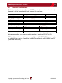
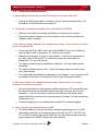
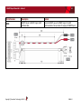
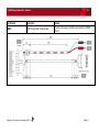
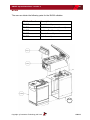
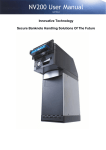
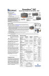
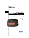
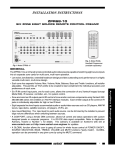
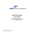
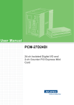
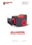
SECTION 2 SMART PAYOUT MANUAL SET FIELD SERVICE MANUAL Innovative Technology assume no responsibility for errors, omissions, or damages resulting from the use of information contained within this manual. SMART Payout Manual Set – Section 2 2 SMART PAYOUT MANUAL SET – SECTION 2 2. FIELD SERVICE MANUAL 3 2.1 Cleaning 3 2.2 Fault Finding - Flash Codes 5 2.3 Tape and Diverter Positions 7 2.4 Technical Specifications 9 2.5 Fault Finding Flow Chart 10 2.6 Frequently Asked Questions 11 2.7 Spare Parts 12 Copyright © Innovative Technology Ltd 2014 GA00860-2 SMART Payout Manual Set – Section 2 2. 3 FIELD SERVICE MANUAL This section is one part of a complete manual set: typically, a field service engineer who is maintaining the product would use this section. This section contains the essential information that the field engineer needs to clean, maintain and fault find a SMART Payout unit that is installed in a host machine. The SMART Payout unit has been designed to minimise any problems or performance variations over time. This has been achieved by careful hardware and software design; this attention to the design means there is very little user maintenance required. 2.1 Cleaning The payout module is effectively a ‘sealed’ unit; as such there are no parts to clean other than the external case. The NV200 Validator has been designed in a way to prevent damage and airborne contamination reaching the optical sensors; however, depending upon the environment the NV200 may require occasional cleaning. Caution! Do not use solvent based cleaners on any part of the Payout or NV200 units. Do not use solvent based cleaners such as alcohol, petrol, methylated spirits, white spirit or PCB cleaner. Using these solvents can cause permanent damage to the units; only use a mild detergent solution as directed below. To clean the NV200 note path, you will need to remove the validator head from the assembly – you cannot open the note path cover when the payout unit is fitted. To remove the NV200 head unit, first unlock the NV200 cashbox and head release lock (if fitted) Then, lift the silver head release catch located on the front of the NV200 Finally, slide the head unit forward and lift it off the chassis Copyright © Innovative Technology Ltd 2014 Head release catch GA00860-2 SMART Payout Manual Set – Section 2 4 After removing the head unit, to open the note path cover, pull the top cover release latch forward (towards the bezel) and lift the cover as shown here (it is recommended to also remove the front bezel to allow correct cleaning of the note path guides): Cover release latch Note path guides The note path is now visible and can be cleaned. Carefully wipe the surfaces with a soft lint free cloth that has been moistened with a water and mild detergent solution (e.g. household washing up liquid) - be very careful when cleaning around the sensor lenses and make sure they are clean and dry before closing the cover and restarting the unit. Caution! Do not use any lubricants. WARNING! Do not try to disassemble Do not lubricate any of the note transport mechanism or any part of the note path, as this can affect the operation of the validator. Do not attempt to disassemble the payout module or validator head – trying to do this could cause personal injury and will damage the unit beyond repair. Copyright © Innovative Technology Ltd 2014 GA00860-2 SMART Payout Manual Set – Section 2 2.2 5 Fault Finding - Flash Codes Both the payout module and the NV200 validator have inbuilt fault detection facilities. If there is a configuration or other error, the payout module status indicators or the NV200 front bezel will flash in a particular sequence. The payout module status indicators are on the rear of the payout module, just below the USB socket: USB Connector Status Indicators A summary of the Status Indicator Flash Codes for the payout module are shown here: Status Indicators Red Flashes Indicated Error Comments 0 No LEDs lit No power 1 Motor / barcode error Check tape in window (see Subsection 2.3 of this manual) 2 3 Note sensor error EEPROM error 4 Payout jammed 5 Diverter error Green 0 1 2 3 4 5 6 7 1 every second Both LEDs on (no flash) Power reset Wakeup from low power Software reset Software command User manual reset Power supply issue Unknown cause None Copyright © Innovative Technology Ltd 2014 Reprogram unit (see Section 3 of this manual set) Remove trapped note (see Section 4 of this manual set) Switch Payout module DIP switch 8 on and off with power on (diverter position shown in Subsection 2.3) Turn power on and off For information only For information only For information only For information only For information only Check power supply For information only All OK GA00860-2 SMART Payout Manual Set – Section 2 6 Summary of the Bezel Flash Codes for the NV200: Flashes Red Blue 0 0 1 2 Indicated Error None Note path open Note path jam 1 3 Unit not initialised 4 1 2 1 2 3 4 1 2 3 Cashbox removed Cashbox jam Firmware checksum error Interface checksum error EEPROM checksum error Dataset checksum error Power supply too low Power supply too high Card format 5 4 1 Payout reset Firmware mismatch 2 3 Copyright © Innovative Technology Ltd 2014 Comments Close note path Remove obstruction and follow the cleaning procedure in Subsection 2.1 of this manual Contact ITL technical support Refit cashbox Remove trapped notes Download new firmware Download new firmware Check power supply Reprogram programming card Turn power on and off Reprogram unit GA00860-2 SMART Payout Manual Set – Section 2 2.3 7 Tape and Diverter Positions The images below show the barcode tape position with the diverter in the open and closed positions, and an indication of the diverter in the OPEN position: Normal tape position – diverter in CLOSED position Normal tape position – diverter in OPEN position Copyright © Innovative Technology Ltd 2014 GA00860-2 SMART Payout Manual Set – Section 2 8 Top view – diverter in OPEN position Diverter Close up – diverter in OPEN position Diverter Copyright © Innovative Technology Ltd 2014 GA00860-2 SMART Payout Manual Set – Section 2 2.4 9 Technical Specifications The full technical specifications for the SMART Payout unit can be found in Section 6, Appendix B of this manual set. A brief summary is given here: DC Voltage Minimum Nominal Absolute limits 10.8 V 12 V Supply ripple voltage 0V 0V Supply Current (when connected to an NV200): Maximum 13.2 V 0.25 V @ 100 Hz Standby Running Peak (motor stall) 400 mA 3A 5A Interface Logic Levels Logic Low Logic High Inputs Outputs (2.2 kΩ pull-up) 0 V to 0.5 V 0.6 V +3.7 V to +12 V Pull-up voltage of host interface 50 mA per output Maximum current sink We recommend that your power supply is capable of supplying 12V DC at 6.3 A. TDK Lambda produces a suitable power supply (model SWS75-12). This power supply is available from a variety of suppliers including Farnell (stock code 1184648) and RS (stock code 466-5904). Copyright © Innovative Technology Ltd 2014 GA00860-2 SMART Payout Manual Set – Section 2 2.5 10 Fault Finding Flow Chart Payout module NV200 Please use this flow chart with the Flash Codes in the previous sub-section as an aid to help resolve any configuration or start up problems you might have with the SMART Payout unit. If you are unsure about the cause or how to resolve the problem, please contact ITL’s technical support department. Support contact details can be found on the ITL website (www.innovative-technology.co.uk), or on the last page of this section. Note trapped in NV200 Note trapped between NV200 and payout module Remove power Remove power Remove validator head Remove validator head Remove obstruction and make sure note path is clean Follow the note path cleaning procedure in Subsection 2.1 of this manual Note trapped inside payout module Follow the manual note extraction procedure in Section 4 of this manual set Remove obstruction and make sure note path is clean Remove cash box and check it is clear Refit validator head Refit cash box and validator head Power up the unit and turn DIP switch 8 ON and OFF Reapply power Unit now ready to restart Copyright © Innovative Technology Ltd 2014 GA860-2 SMART Payout Manual Set – Section 2 2.6 11 Frequently Asked Questions a. What settings should I use on the DIP switches on the rear of the unit? Look at the DIP switch tables in Section 1 of this manual set (subsection 1.4). By default, all DIP switches are turned OFF. b. The payout unit does not securely lock on the back of the NV200 Make sure the plastic mountings are fitted on the back of the cashbox. Ensure the payout module is correctly located on the mountings before the validator head is installed. c. My notes are always stacked in the cashbox even though I have chosen for them to go into the payout unit Check that the Green LED on the rear of the SMART Payout unit is flashing – see the Flash Codes in subsection 2.2 if this is not the case. Make sure the diverter is in the correct position – with the unit powered up turn DIP switch 8 ON and OFF to make sure (check the information in subsection 2.2 if you are unsure). The Payout module might be disabled in software - send an enable payout command. The Payout module might be full – check how many notes are stored using your host software. The notes might be detected as damaged or not straight – in this case they will be stacked in the cash box so that they will not jam the payout module. d. My payout module has stopped functioning and I want to return it for repair however it has bank notes inside All bank notes that are inside payout modules returned to ITL are handled with the highest security and carefully tracked internally until their return to the customer - if you do not want to ship the unit with the bank notes inside, please follow the instructions for manual payout in Section 4 of this manual set (subsection 4.10). If manual emptying is not possible please contact ITL technical support. e. Can I connect to the Host machine via USB? The direct USB port is for on the bench testing/Programming only. If a USB connection is desired, we recommend going through our IF17. The IF17 is a TTL to USB conversion box which filters out any noise and provides a smooth signal between the SMART Hopper and Host machine. Copyright © Innovative Technology Ltd 2014 GA860-2 SMART Payout Manual Set – Section 2 2.7 12 Spare Parts Full details of the interface cable connector pinouts, connector types / makes and other related information can be found in Section 4 of this manual set. Payout Module The Payout Module is a ‘sealed’ unit and there are no user-replaceable spare parts. However, several cables designed to be used with the module are available, and these are listed below: ITL Part Number Description Details CN214 USB Cable USB 2.0 Compliant Type A to Type B cable Notes: Not to be used for Host communications. Programming Only. USB cable should be USB 2.0 compliant, electrically shielded and less than 5 metres long. Copyright © Innovative Technology Ltd 2014 GA860-2 SMART Payout Manual Set – Section 2 13 ITL Part Number Description Details CN370 SMART Payout power cable Provides 12V supply only to SMART Payout Copyright © Innovative Technology Ltd 2014 GA860-2 SMART Payout Manual Set – Section 2 14 ITL Part Number Description Details CN391 SMART Payout to SMART Hopper eSSP interface cable Connects SMART payout to SMART hopper for eSSP communications. Also provides 12V supply to SMART Payout Copyright © Innovative Technology Ltd 2014 GA860-2 SMART Payout Manual Set – Section 2 15 Part Number Description Details CN397 SMART Payout eSSP interface cable Provides 12V supply and eSSP communications to SMART Payout Copyright © Innovative Technology Ltd 2014 GA860-2 SMART Payout Manual Set – Section 2 16 NV200 The user can obtain the following parts for the NV200 validator: ITL Part Number Description PA610 Bezel Assembly PA621 NV200 Validator Head Assembly PA629 Cashbox Final Assembly PA640 Chassis Assembly PA650 Lock Assembly PA640 Copyright © Innovative Technology Ltd 2014 GA860-2