1
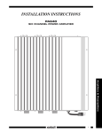
INSTALLATION INSTRUCTIONS
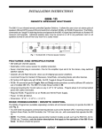
ZPR68-10
SIX ZONE EIGHT SOURCE REMOTE CONTROL PREAMP
ZONE CONTROL - IR INPUTS
ZPR68-10
+12V
SIX ZONE EIGHT SOURCE REMOTE PREAMP
A
GND
80
STATUS
COMMON IR INDICATOR
COMMON IR LEVEL
IR IN
C
90
3
4
50
D0
5
6 INPUT 7
A0
A
ADJ-OFF
10
2
C0
40
1 2 3 4 5 6 7 8
HI
LO
B
48
1
00
01
41
8
B0
21
20
E0
70
F0
61
TREBLE
BASS
Z-ADJ
30
VOL
60
88
18
98
08
A8
28
E8
78
F8
E-FLAT
LAST
MAX-V
TRIM
68
C8
GLOBAL
1
2
3
4
5
6
7
8
09
MUTE
COMMON IR OUTPUTS
IR CONFIRM
ZONE IR OUTPUTS
38
ON
1
2
3
4
5
6
7
8
1
SOURCE INPUTS
COM
PORT
2
3
4
5
6
OFF
ZONE OUTPUTS
E1
58
B8
29
OFF
69
D8
49
A9
E9
C-BAL
89
C9
71
19
59
39
79
F1
99
D9
B9
F9
VIDEO
VIDEO
L
L
AUDIO
AUDIO
POWER
R
R
SOURCE INPUTS
ZONE OUTPUTS
CO
G
RC68+ PROGRAMMER
POWER
SUPPLY
® SYLMAR, CA • MADE IN U.S.A.
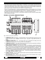
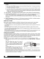
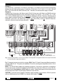
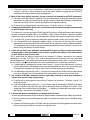
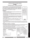
Fig.1 Model ZPR68-10
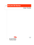
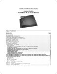
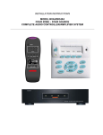
Fig. 2 Model RC68+
Handheld Programmer
(available separately)
GENERAL
The ZPR68-10 is an infrared remote controlled audio/video preamp capable of switching eight source inputs
into six separate zone cards for multi-zone, multi-room operation.
• Low noise, low distortion, extended headroom design provides outstanding sonic performance in a highly
versatile multi-room, multi-zone design.
• Each zone has separate Volume, Max. Volume, Mute, Balance, Bass and Treble functions, all installer
adjustable. This permits an "EQ" profile to be created to best compliment the individual acoustics and
preferences of each zone.
• Zone and common IR outputs permit IR control of zone and/or common components using Xantech 282/
283/284/286 series mini emitters or 794/797 interface modules. Each emitter output at the common IR
jacks is individually adjustable for high or low IR level.
• Eight separate line level inputs accommodate audio or audio/video sources such as CD players, AM/FM
tuners, tape decks, satellite receivers, LD players, VCR's, etc.
• Input Level Matching. The input level for each audio source can be trimmed by the installer to prevent
large volume differences when switching between sources.
• A COM PORT, using a female DB9 connector, allows full control and status operations with custom
designed panels or computer programs. It is RS-232 data signal compatible. Refer to Application
Advisory, Volume 2, Number 1, for details. This advisory is available on Xantech's web site at
www.xantech.com and http://www.xantech.com.engineer for updates.
• A GLOBAL function allows the user to gang all zones for whole house control of POWER ON/OFF,
SOURCE SELECTION, BASS, TREBLE, VOLUME and MUTE functions ("party mode"). GLOBAL
operation can be prevented in any given zone by using the MUTE command.
1
Amplifiers & Preamplifiers
• Six IR IN control input ports, one for each zone, allows the connection of any Xantech keypad (except
Model 598), IR receiver, controller, etc., for system control.
• Zone STATUS and CO (common control) Outputs. An ON/OFF +12 V DC output is provided from each
zone and one common to all zones. When a zone(s) is turned ON, these outputs can drive remote room
ON/OFF STATUS indicators and/or drive the voltage sensing inputs (CI) of the PA1235 or controlled AC
power strips for power management of zone amplifiers and common sources.
• RC68+ IR Remote/Programmer. Available separately, the RC68+ (or RC68) includes all the IR control
codes necessary for the setup and operation of the ZPR68-10. Normally, the RC68+ commands would
be "taught" into Xantech learning keypads, remotes, etc., for eventual use by the client.
• Zone expansion, in one zone increments, is provided by a separately available expansion module, Model
EXP9, and zone PCB cards.
ZPR68-10 PANEL DESCRIPTIONS
1
2
3
4
ZONE CONTROL - IR INPUTS
ZPR68-10
+12V
SIX ZONE EIGHT SOURCE REMOTE PREAMP
GND
COMMON IR LEVEL
STATUS
COMMON IR INDICATOR
IR IN
15
1 2 3 4 5 6 7 8
HI
LO
1
2
3
4
5
6
7
5
8
6
14
COMMON IR OUTPUTS
IR CONFIRM
1
13
3
4
5
6
7
8
1
2
SOURCE INPUTS
COM
PORT
12
2
ZONE IR OUTPUTS
10
4
5
6
VIDEO
VIDEO
L
L
AUDIO
AUDIO
R
R
POWER
SOURCE INPUTS
11
3
ZONE OUTPUTS
ZONE OUTPUTS
CO
G
POWER
SUPPLY
® SYLMAR, CA • MADE IN U.S.A.
9
8
7
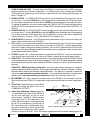
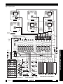
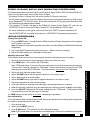
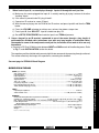
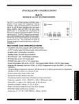
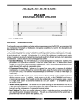
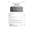
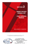
Fig. 3 ZPR68-10 Panel Features and Functions
1. COMMON IR LEVEL DIP Switches. These DIP switches set the output power level to HI or LO for
emitters connected to the COMMON IR OUTPUT jacks. See item 4, under INSTALLATION, for
details.
2. COMMON IR INDICATOR LED. This flashes when any IR commands are being sent to the
COMMON IR OUTPUT jacks (even when emitters are not plugged in).
3. COMMON IR OUTPUTS. These eight 3.5mm mono mini jacks are for the connection of emitters to
control source components that are common to all zones.
4. ZONE CONTROL - IR INPUTS. Each zone of the ZPR68-10 is individually controlled through these
ports. Three of the four screw terminals on each plug-in connector are for connection, via the standard
Xantech 3-wire bus, to any Xantech IR receiver, keypad (except Model 598), or controller. The
remaining terminal, STATUS, provides a control output of +12 volts that turns on and off with the zone
ON and OFF commands to drive status indicators and/or the voltage sensing ports of power amplifiers,
such as the CI Inputs of a PA1235 or AC power strips. The connector markings are defined as follows:
+12 V, GND, STATUS and IR IN (IR signal).
5. ZONE IR OUTPUTS. These six 3.5mm mono mini jacks are for the connection of emitters to control
components dedicated to any zone.
6. Zone IR Indicator LED's. These six LED's, one for each zone, flash to indicate when a zone is
receiving IR commands from any IR receiver, keypad, etc.
2
ZPR68-10
7. ZONE EXPANSION PORT. This port allows the ZPR68-10 to be linked with an EXP9 expansion
module to provide up to 15 zones of operation. The EXP9 includes 9 slots, allowing zone XCARDs
(PCB cards) to be added one by one in the field, or purchased already installed from the factory, for
zones 7 through 15.
8. ZONE OUTPUTS. The ZONE OUTPUTS consist of six sets of audio/video RCA type jacks - one set
for each zone. The L and R AUDIO jacks are connected to the appropriate Left & Right input jacks
on a main power amplifier for the zone and the VIDEO jack to the composite Video input on a zone
TV monitor or modulator. Any source connected to the SOURCE INPUTS can be switched to these
ZONE OUTPUTS when the zone receives an RC68+ INPUT command at the ZONE CONTROL - IR
INPUTS.
9. SOURCE INPUTS. The SOURCE INPUTS consist of eight sets of audio/video RCA type jacks - one
set for each input. The L and R AUDIO jacks and the VIDEO jack are connected to the corresponding
Left & Right audio and Video output jacks (where applicable) on up to eight source components
(satellite receivers, LD players, VCR's, AM/FM tuners, CD changers, etc.).
10. POWER SUPPLY Connector. 6-Pin DIN jack permits connection of a high current multi-voltage AC
power supply (included with each ZPR68-10).
11. CO Terminals. These two terminals provide a Control Output that goes high (+12 volts) when any zone
is first turned ON and goes low (0 volts) when the last zone is turned OFF. Use this control voltage
to drive the voltage sensing ports of power amplifiers, such as on the PA640 and the PA1235, and/
or AC power strips to provide power on/off for the common source components and/or to drive a total
system power on/off status indicator.
12. POWER Indicator LED. Indicates when power is applied to the ZPR68-10. It stays on continuously
even when all zones are turned off (as long as AC power is applied to the plug-in power supply).
13. COM PORT. This DB9 female connector permits 2-way communications with the ZPR68-10 using
custom designed control panels or computer programs. Port is RS-232 signal compatible, allowing
bidirectional data interface for status readout of ZPR68-10 settings as well as control of operational
functions.
14. IR CONFIRM LED. Flashes when IR commands native to the ZPR68-10 are received & executed.
Won't flash when non-ZPR68-10 IR commands are passed through to operate source components,
etc.
15. Cover Panel. Remove this to access the 8 DIP
switches for setting the power level of the
COMMON IR OUTPUTS.
16
Zone PCB
Video Gain
Adjustment Pins (PJ1)
Jumper
16. Video Gain Adjustment Jumpers (internal).
The video gain of each zone on the ZPR68-10
Zone A/V
Zone Control
Output Jacks
IR Input Jack
can be set to two levels, by the use of an
internal jumper. See Fig. 4 . With the jumper
on one pin only of PJ1, the video gain is unity
(0 dB). When the jumper is inserted onto both
Jumper
Jumper
Shown in
Shown in
pins of PJ1, the video gain is increased by +3
+3 dB Position
0 dB Position
dB. You should use the +3 dB position only if
Fig. 4 Video Gain Adjustment - Jumper Locations
you notice a reduction in picture contrast and
brightness when running long cable lengths
(usually in excess of 150 feet). Since the majority of applications will not require additional gain, all
ZPR68-10
3
Amplifiers & Preamplifiers
COM PORT - RS232 Application Information. Use of this port requires proficiency in computer
programming and hardware interfacing. Refer to application Advisory, Volume 2, Number 1, for basic
communications protocol and hardware connection details. This advisory is available on Xantech's
web site at www.xantech.com/products/alist/htm. For more detailed information, including latest
updates, go to: http//www/xantech.com.engineerand make your selections from the list.
ZPR68-10's are shipped from the factory with the jumper installed on one pin only (0 dB).
To gain access to the jumpers you will need to remove the top cover as follows.
a) Remove power supply plug from the Power Supply jack on the ZPR68-10 (if currently plugged in).
b) Remove the five (5) screws on each end of the top cover.
c) RAemoive the six (6) screws just under the six Video jacks of the Zone Outputs.
d) Remove one (1) screw just below the Power LED.
e) RAemove the two (2) hex nut screws from the COM PORT.
f) Carefully lift the cover off.
g) When reassembling, be sure to carefully align the holes in the top cover with the jacks and the LEDs
on all the PCB's before pressing it down into place and replacing the screws.
RC68+ PROGRAMMER / REMOTE CONTROL
The RC68+ (and the RC68) programmer, available separately, contains all the commands necessary to set
up and operate the ZPR68-10.
• In addition, you will need it to program the universal learning devices actually used by the client, such as
the Xantech URC-1 learning remote, the Xantech Smart Pads, the 590 Programmable Controller, the 710
Fone Link, etc.
• While the RC68+ will operate as a separate remote control, it is highly recommended it not be given to
the final user for the following reasons:
• First, since it includes special setup codes, the user may inadvertently alter the installer configurations.
• Also, since the user will require IR commands from other brands of equipment to control the total system,
in addition to those for the ZPR68-10, all commands should be consolidated into one learning device, for
ease of use.
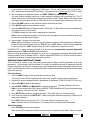
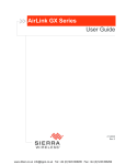
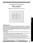
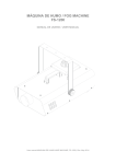
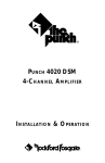
RC68 BUTTON DESCRIPTIONS
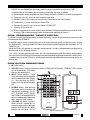
1. IR Emitter Lens
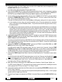
2. ADJ-OFF button. Provides instant turn-off of the TRIM and Z-ADJ modes. TRIM and Z-ADJ will also
turn off automatically 10 seconds
1
1
after the last button press.
80
15
48
10
90
1
2
3
4
C0
50
D0
40
6 INPUT 7
A0
A
ADJ-OFF
00
5
16
C
01
41
3
8
30
B0
21
GLOBAL
20
E0
70
F0
TREBLE
BASS
Z-ADJ
VOL
60
88
18
98
08
A8
4
Rear
61
5
09
MUTE
F8
E-FLAT
LAST
MAX-V
TRIM
68
C8
58
D8
49
6
69
7
89
C9
A9
E9
71
19
59
39
79
3456
E1
8
789A
9
789A
CDE
C-BAL
3456
78
OFF
10
D9
B9
F9
CODE GROUP
789A
789A
C DD
BBC EE
9A
78
789A
3 43 54 65 6
99
3 43 54 65 6
F1
12
F0
F 012
11
29
E8
B
12
B8
OFF
28
F 012
F 012
13
38
ON
F 012
14
CDE
4
17
B
B
5. VOLUME Up/Down buttons.
When pressed, volume will increase and decrease in 2 dB steps
between 0 dB and -80 dB. When
buttons are held down, the vol-
2
A
CCDD
BB EE
4. GLOBAL button. After pressing
this button (within 5 seconds) all
subsequent commands (i.e. INPUT, VOLUME, MUTE, BASS,
and TREBLE) will be applied to all
zones, in addition to the addressed
zone, from any zone location.
18
F 012
3. INPUT Select buttons. Press
these to select up to 8 audio/video
sources connected to the ZPR6810. Also, pressing any INPUT
button turns the addressed zone
ON.
19
Front
20
RC68+ PROGRAMMER
Fig. 5 RC68 Functions
ZPR68-10
ume level will ramp continuously. When a zone is turned OFF, then ON again, or if power is interrupted,
the volume will return to its last setting.
6. MUTE ON / OFF buttons. Separate On / Off buttons give positive mute commands without knowing
what the status is. This is very helpful in a remote room when all adjustments are made “blind” without
any visual aids for status.
NOTE: Mute is released (audio on) when a VOLUME, INPUT, BALANCE, BASS or TREBLE
command is sent, in addition to MUTE OFF.
7. TRIM button. Activates the Input Level Trim mode. This allows level trimming of each input on the
ZPR68-10 so that all sources will sound equally loud when switching from one source to another (see
ADJUSTING INPUT LEVEL TRIM procedure). The TRIM mode will turn off automatically 10 seconds
after the last button is pressed, or, it can be instantly defeated by pressing the ADJ-OFF button.
8. MAX-V button. Saves the maximum desired volume level for the zone when in the Z-ADJ mode (see
ZONE ADJUSTMENTS procedure).
9. BALANCE buttons. When the BALANCE "arrow" buttons are pressed, the audio output will move to
the left or right in 2 dB steps with each left or right press. (NOTE: No change will occur if they are held
down continuously).
10. Balance "Center" button. This button, when pressed (identified by a "—" mark), will instantly return
the balance to the center position from any previous setting.
11. OFF button. Turns the zone OFF. The ZPR68-10, however, remains in "Standby" mode, ready for
zone turn-ON when any INPUT button is pressed.
12. LAST button. Returns to the last adjusted values when comparing customized tone and balance
settings to electrical flat (E-FLAT). Refer to ZONE ADJUSTMENTS procedure.
13. E-FLAT button. Switches the tone settings to electrical flat (flat frequency response) and the balance
to center from customized settings. In conjunction with the LAST button, it allows instant audible
comparisons during setup procedures. Refer to ZONE ADJUSTMENTS procedure.
14. TREBLE & BASS control buttons. When the "arrow" buttons are pressed, the treble and bass
response can be increased or decreased from 0 dB to ± 12 dB in 2 dB steps with each up or down press.
(NOTE: No change will occur if they are held down continuously).
15. Treble & Bass "N-Flat" buttons. These buttons, when pressed (identified by a "—" mark), will
instantly return the treble and bass to the "N-Flat" values (nominal or EQ'd" values) from any previous
settings the user may have used.
16. Z-ADJ button. Activates the ZONE ADJUSTMENTS mode, allowing customized bass, treble, balance
and max. level settings for each individual zone. Z-ADJ will turn off automatically 10 seconds after the
last button press, or, it can be instantly defeated by pressing the ADJ-OFF button. Refer to ZONE
ADJUSTMENTS procedure.
17. Code Group Numbers. Each button face on the RC68+ is marked with a Code Group Number
identifying a total of 55 different IR Remote Control Code Groups.
These code groups allow Xantech products that use RC68+ codes, to have a different code group
assigned to each one. This prevents mutual interaction when both are used on the same IR bus in an
IR system. This also permits the installer to change the code group in the field if two or more of the same
Xantech model are used on the same IR bus.
Refer to the INSTALLER INSTRUCTIONS that come with the RC68+ for Code Group Setting
Procedures.
ZPR68-10
5
Amplifiers & Preamplifiers
Use these controls to "EQ" (equalize) the sound for each zone's acoustic differences during the "ZADJ" settings. The values arrived at become the "N-Flat" values ("EQ'd" values) for the user.
NOTES:
a) Each zone of the ZPR68-10 can be set to its own individual Group Code. This may be useful when
the system requirements so dictate.
b) The Code Group Number assigned and preset at the factory for each zone of the ZPR68-10 is 68.
c) Since other Xantech IR controlled models are assigned and preset at the factory to different Code
Groups, it is unlikely that you will ever need to change the Code Group on the zones of the ZPR6810 away from the factory preset number of 68.
18. A, B, C buttons. These operate special control functions on other Xantech IR controlled products.
19. Code Group Setting Switches. These rotary switches are for setting and selecting the specific IR
Remote Control Code Groups. These must be set to 68 to work with the ZPR68-10!
Refer to the INSTALLER INSTRUCTIONS that come with the RC68+ for Code Group Setting
Procedures.
20. Battery Compartment. Holds two 1.5V "AA" batteries that power the RC68+. Use Alkaline batteries
for longest life. Slide cover in the direction of the arrow for removal.
INSTALLATION
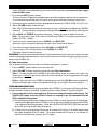
Fig. 6 shows a typical installation of a ZPR68-10 utilizing all 8 source inputs and all 6 zone outputs.
• A variety of Xantech IR receivers and keypads control the zones and the source equipment.
• The STATUS terminal on each zone provides zone ON/OFF indication on their respective IR receivers
and keypads.
• Two Xantech PA640 Power Amplifiers drive the stereo pairs of speakers in each of the six zones.
• The common CO terminal provides AC power ON/OFF management for the PA640's and for the common
sources through GATEKEEP-IRTM.
Note: All source components in this typical system must have their ON/OFF function controlled by IR. See
the GATEKEEP-IR Installation Instructions for all GATEKEEP-IR programming procedures.
CONNECTION PROCEDURE
The following procedure is based on Fig. 6, and assumes that all rooms in the house, where remote
controlled A/V signals are desired, have been pre-wired with home runs of 4-conductor cable, coaxial cable
and speaker wires. In addition, all IR receivers, keypads and speakers have been connected in each room,
and the system is ready for installation of the ZPR68-10 and other components.
CAUTION: Be sure no power is applied to any of the components until all connections are made.
1. Make connections from each of the zone 4-conductor cables to the ZONE CONTROL - IR INPUTS
terminals.
Note that in Fig. 6 only zones 2 & 3 have IR
Ground Shield as shown
receivers - the rest are keypads. This assumes
ZPR68-10
the use of learning remotes capable of macro
Zone
Input
(sequence) programming for GATEKEEP-IR funcTerminals
tions.
Shielded Cable
470 Ohm
resistor
SPECIAL NOTE: When using long lengths (>50 to remote room
feet) of inter-room shielded cable, it may be
Fig. 7 Using 470 Ω Capacitance Discharage Resistor
necessary to connect a 470 Ohm 1/8 Watt resistor
between Input (signal) and Gnd at the IR input terminals of the ZPR68-10. The resistor discharges
the cable capacitance more quickly, allowing IR codes of high bit rates to pass without data loss for
consistent command executions. See Fig. 7.
+12V
GND
STATUS
IR IN
6
ZPR68-10
Fig. 6 Typical System
RF IN
RF IN
XANTECH
TV
TV
S-62/64/66
Wall Speakers
MONITOR
R
L
MONITOR
R
L
780-80
"J" Box
IR Receiver
ZONE 2
R
L
Smart
Pad 2™
Smart
Pad 2™
ZONE 4
ZONE 5
VIDEO IN
XANTECH
TV
TV
MONITOR
MONITOR
S-62/64/66
Wall Speakers
R
L
VIDEO IN
R
L
Smart
Pad 2™
Smart
Pad 2™
ZONE 1
R
L
4-Conductor
Home Runs.
480-00
Dinky Link™
IR Receiver
CAUTION
Smart
Pad 2™
See
"POWER SUPPLY
CONSIDERATIONS"
Section
ZONE 3
ZONE 6
RF Signal
IR Signal
RF (TV)
Signal.
Use
RG-6
Coax
ZONE CONTROL - IR INPUTS
ZPR68-10
+12V
SIX ZONE EIGHT SOURCE REMOTE PREAMP
GND
STATUS
COMMON IR INDICATOR
COMMON IR LEVEL
Base
Band
Video.
Use
RG-6
Coax
IR IN
3.5-to-3.5mm
Mono Mini Plug
cable.
Use part
#6017400.
1 2 3 4 5 6 7 8
HI
LO
1
2
3
4
5
6
7
8
COMMON IR OUTPUTS
IR CONFIRM
1
2
3
4
5
ZONE IR OUTPUTS
6
7
8
1
2
SOURCE INPUTS
COM
PORT
3
4
5
6
ZONE OUTPUTS
ANT. or
Cable
VIDEO
VIDEO
L
L
AUDIO
AUDIO
R
R
2-Way
POWER
RF
Amp
SOURCE INPUTS
Combiner
ZONE OUTPUTS
CO
G
To 120 V AC
(unswitched)
Modulator
(2-Input)
POWER
SUPPLY
® SYLMAR, CA • MADE IN U.S.A.
782-00
Power
Supply
Loop video thru to
ZPR68-10 Video Inputs
(if necessary).
Plug SAT Rec'rs into
120 V AC (unswitched)
A/V
Patch Cords
IR IN
GMM1A
VIDEO OUT
VIDEO IN
GVM1
POWER
CONFIRM
12VDC
IR OUT
G
S
CI
+12V
To Sat #1
Video OUT
SAT Rec'r #1
To Sat #2
Video OUT
2-Conductor
Mini-Plugto-Stripped
Ends. Use
6015900.
A/V
Patch Cords
V
L R
AM/FM Tuner
R
L
R
Remote
ON/OFF
Remote
ON/OFF
L
STATUS
ON
IR OUT
SAT #1 Emitter
GVM1
VIDEO IN
VIDEO OUT
STATUS
ON
IR OUT
SAT #2 Emitter
GCM1
CURRENT
SENSOR
THRESHOLD
STATUS
ON
IR OUT
VCR #1 Emitter
GCM1
CURRENT
SENSOR
THRESHOLD
STATUS
ON
IR OUT
VCR #2 Emitter
Gate
#3
Gate
#4
Gate
#7
GCM1
CURRENT
SENSOR
GCM1
CURRENT
SENSOR
THRESHOLD
Gate
#5
Gate
#6
Gate
#8
DVD Emitter
STATUS
ON
IR OUT
CD Emitter
ON
STATUS
IR OUT
AM/FM Tuner Emitter
Gate
#2
GCM1
CURRENT
SENSOR
THRESHOLD
GCM1
CURRENT
SENSOR
THRESHOLD
STATUS
ON
IR OUT
THRESHOLD
STATUS
ON
IR OUT
LD Emitter
Gate
#1
VCR #1 Pwr
VCR #2 Pwr
CD Changer
SAT Rec'r #2
Current
SENSOR
V
L R
Current
SENSOR
To
IR OUT,
Gate #7
LD Pwr
DVD Pwr
To
IR OUT,
Gate #2
Current
SENSOR
Current
SENSOR
VCR #1
V
L R
V
CD Pwr
Tuner Pwr
Current
SENSOR
Current
SENSOR
DVD Player
To
IR OUT,
Gate #6
To
IR OUT,
Gate #3
VCR #2
L R
V
L R
V
LD Player
L R
ZONE 1
Plug ALL Current
SENSORs into 120 V
AC (unswitched).
GATEKEEP-IR
ZPR68-10
To
IR OUT,
Gate #8
To
IR OUT,
Gate #1
To
IR OUT, Gate #4
To
IR OUT, Gate #5
283M
Blink-IR™
Mouse
Emitter (8)
SOURCE COMPONENTS
ZONE 2
ZONE 3
To Speakers in Rooms
To
120V AC
(Unswitched)
ZONE 4
ZONE 5
To
120V AC
(Unswitched)
ZONE 6
To Speakers in Rooms
ZONE AMPLIFIERS - MODEL PA640 (2)
7
Amplifiers & Preamplifiers
ZPR68-10 Power
Supply
2. Connect the audio and video Output jacks on each of the audio/video source components to the
SOURCE INPUTS jacks on the ZPR68-10.
3.
4.
5.
6.
7.
8.
9.
10.
11.
Use high quality audio and video RCA-type patch cords.
Place a model 283M Blink-IR Emitter on the IR sensor window of each source component, and plug
them into the IR OUT on the appropriate GATEKEEP-IR modules. Connect one of the COMMON IR
OUTPUTS on the ZPR68-10 to the IR IN of the GMM1A module on the GATEKEEP-IR.
In cases where you may connect emitters directly to the COMMON IR OUTPUTS, you may need to
change the COMMON IR LEVEL DIP switch settings (item #1). To do so, remove Cover Panel (item
#15). All are set to the LO position at factory.
Consider the following factors when choosing HIgh or LOw power settings for the source emitters:
a) In the majority of cases, when you mount an emitter on the IR sensor window of the controlled
device, you would use the LOw power mode. This prevents overload of high gain sensor circuits,
for best operation.
b) The HIgh power mode may be used when you mount the high output 282M emitters on an adjacent
shelf or door a short distance from the unit's sensor. Another instance is when you place an emitter
inside the device, but cannot place it close to the IR sensor. In such cases, you may need the high
power setting to blast through printed circuit boards or around chassis structures, etc. In addition,
when using the lower output 283M and 286M Blink IR's, you may need the high power mode for
some devices that have less sensitive IR sensors.
Connect the common CO and G terminals (item #11, located just under the POWER indicator) to the
REMOTE ON/OFF inputs on the two PA640 Power Amplifiers and to the + and – terminals of the
GMM1A Module of the GATEKEEP-IR.
You may use two of the Xantech part #6015900 five foot 2-conductor cables (3.5mm mini plug on one
end and stripped tinned ends on the other) for connection to the PA640's. Connect the white-striped
side to CO and the other to G.
Connect the AUDIO L and R ZONE OUTPUT jacks on the ZPR68-10 to the CH1, CH2, etc., LINE
INPUT jacks on each of the PA640 Power Amplifiers.
Use high quality audio RCA type patch cords. You may connect the L channels from the ZONE
OUTPUTS on the ZPR68-10 to CH1, CH3 & CH5, respectively, on the PA640 's and the R channels
to CH2, CH4 & CH6. Be sure to follow this through when connecting the speaker leads so that the L
and R channels are correctly connected to the Left and Right speakers in the rooms.
Connect the VIDEO outputs from Zones 3 and 6 to a Video Input on the TV monitors in zone rooms
3 and 6.
Use RG-6 coaxial cable with RCA type phono plugs on each end. You may need to adjust the Video
Gain on the zone cards if you have coaxial cable runs greater than 150 feet. See Fig. 4 for details.
Connect the VIDEO outputs from Zones 2 and 4 to the Video Inputs of a 2-Input Modulator.
Use high quality RCA type video patch cords.
Make the necessary connections of the Modulator to the Combiner, Cable System, Splitter, etc.
Use RG-6 coaxial cable with "F" connectors on each end to connect each device, including the coaxial
cables going to the RF IN on the room TV's in Zones 2 and 5.
Connect the speaker leads from each Zone room to the corresponding SPEAKERS terminals on the
PA640 Power Amplifiers.
Be sure to observe correct L and R channel assignment and speaker phasing (+ and –). Use 14 gauge
speaker wire for lengths up to 200 feet.
Plug the Power Supply (included with the ZPR68-10) into the DIN jack marked POWER SUPPLY (item
#10).
8
ZPR68-10
12. Plug the power cords from 6 of the Source Components into the Current Sensors of the GCM1
GATEKEEP-IR modules. In turn, plug the Current Sensor units into unswitched 120 VAC outlets. Also,
plug the two SAT receivers into 120 VAC unswitched AC outlets. In this particular setup, the SAT
receivers use the GVM1 video sensing modules rather than current sensing. Refer to the GATEKEEPIR Installation Instructions for all GATEKEEP-IR programming procedures.
13. Set all power switches on the PA640's to the OFF MANUAL (REMOTE ON/OFF) position.
14. Plug all remaining power cords into unswitched 120V AC outlets.
CAUTION: When configuring your own particular system, be sure to take into consideration the power
demands of all keypads, IR receivers, etc. See POWER SUPPLY CONSIDERATIONS on the following
page. When you have done this and completed all connections, the ZPR68-10 system would then be ready
for the Setup and Operating Procedures.
POWER SUPPLY CONSIDERATIONS
The total current available from the +12V, the STATUS and CO (control out) terminals on the ZPR68-10
to power keypads, infrared receivers, switching devices, etc., is 1.8 A. In addition, each of the zone STATUS
terminals and the CO terminal have a current limit of 90 mA each max. These currents are enough to power
all but the most unusual installations. However, if you have a system where the total current demand
does exceed 1.8 A, then an external power supply(s) must be used to power the extra devices to
prevent overheating and shutdown of the ZPR68-10.
The following table shows the current required by Xantech devices typically used with the ZPR68-10 in
zoned-controlled multi-room systems:
DEVICE
IR Receiver Models
291-10, 480 series, 490/495 series,
780-10
291P, 291-455, 780P, 780-455
(hi-frequency types)
291-80, 480-80, 780-80 (CFL types)
780-80 Status LED
Models With Control Inputs
PA640 6 Channel Power Amplifier
PA1235, 12 Channel Power Amplifier
599 Pulsed Switching Module
CC12 and SR21 Relay Modules
10 mA
15 mA
20 mA
10 mA
65 mA
85 mA
5 mA
11 mA
16 mA
11 mA
1 mA
Procedure
Add up the current demands for the devices used in the system. If the total current exceeds 1.8 A, it is then
necessary to use a 782-00 power supply to separately power the V or +12V terminals of the additional
devices that cause the over-current condition. See typical connection diagram, Fig. 7.
Note: The STATUS or CI (Control Inputs) of the devices must remain connected to the respective zone
STATUS and common CO terminals on the ZPR68-10, where used. Also, if you exceed 90 mA on any of
these terminals, use a Xantech CC12 Remote Relay Module to reduce the current demand. Refer to the
CC12 Installation Instructions, Fig. 6, for details.
ZPR68-10
9
Amplifiers & Preamplifiers
Keypad Models
730 SmartPad
SmartPad2, SmartPad3, WPK
SmartPad2 & 3 Status line (PM110, LM110,
& WPK series)
CURRENT DEMAND
Example 1
Four Smart Pad2’s (with Status), five 780-80’s (with Status), two PA640’s and one 599 Pulsed Switching
Module are used. Add up the currents: (4 x 90 mA) + (5 x 30 mA) + (2 x 11 mA) + (1 x 11 mA) = 543 mA
total. This is well within the 1.8 A (1800 mA) limit. Therefore, no external power supply is needed.
Example 2
24 Smart Pad2’s (4 per zone, with Status), twelve 780-80’s (2 per zone, with Status), two PA640’s and one
599 Pulsed Switching Module are used. Add up the currents: (24 x 90 mA) + (12 x 30 mA) + (2 x 11 mA)
+ (1 x 11 mA) = 2553 mA total current. This exceeds the 1.8 A limit by 753 mA. Therefore, a 782-00 external
power supply is needed to power the extra Smart Pad2’s and IR receivers that cause the 1.8 A limit to be
exceeded. In this case, you would have to power seven Smart Pad2’s and five 780-80 IR Receivers
externally (780 mA) to ease the load sufficiently.
V
V
V
IR
IR
IR
ST
ST
ST
G
G
G
780-80
"J" Box
IR Receivers
(Five shown)
V
V
V
V
IR
IR
IR
IR
ST
ST
ST
ST
G
G
G
G
Smart Pad2 or 3
(Four shown)
V
V
IR
IR
ST
ST
G
G
V = +12V
IR = IR Signal
ST = Status
G = GND
+12V
(white
striped
side)
+12V
GND
2
1
3
4
5
6
7
8
9
CB18
GND
ZONE CONTROL - IR INPUTS
+12V
"The Strip-IR"
Connecting Block
GND
782-00
Power Supply
STATUS
IR IN
120 V AC
(Unswitched)
ZPR68-10
Zone Control - IR Inputs section
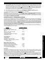
Fig. 7 Using a CB18 to provide a +12V DC rail (if needed) to externally power extra keypads and IR receivers to prevent overload
of the internal power supply of the ZPR68-10.
Fig. 7 illustrates how you can do this by using a CB18 "Strip-IR" Parallel Connecting Block to provide a
separate +12V DC rail. This powers the additional IR receivers and keypads independent of the +12V of
the ZPR68-10.
NOTE: The 782-00 Power Supply has a capacity of 1000 mA. If you have a system that is so extensive
that the total current exceeds the 1.8 A limit of the ZPR68-10 by more than 1000 mA, use two 782-00's
connected so that two separate +12V DC rails are created. Connect two groups of the extra devices so
that the total excess load is shared equally between the two 782-00's.
CAUTION: To prevent current "hogging" and power supply shutdown, never connect a 782-00 in parallel
with the +12V terminal of the ZPR68-10 or in parallel with another 782-00!
10
ZPR68-10
ZPR68-10 BASIC SETUP AND OPERATING PROCEDURES
The following procedures assume the prior connection of all eight SOURCE INPUTS and two PA640's in
a fully wired six-zone system similar to that shown in Fig.6.
• Each zone IR IN has a Xantech Key Pad and/or Xantech IR Receiver connected.
• For AC power management, six of the common sources are current sensed and two are video sensed
by the Gatekeep-IRTM for ON/OFF status. All are switched ON and OFF by sequenced commands from
the SmartPads and programmable remotes.
• The Common CO (Control Out) port on the ZPR68-110 controls System Power OFF status for the
GATEKEEP-IR and also turns the PA640's ON and OFF via their Remote ON/OFF inputs.
• All source components in this typical system must have their ON/OFF function controlled by IR.
• See the GATEKEEP-IR Installation Instructions for all GATEKEEP-IR programming procedures.
SETUP PROCEDURES
Turning The System ON
1. Press an INPUT button (1 through 8) on the RC68+ hand held Remote Programmer while aiming at
an IR receiver in any zone.
Note: All setup instructions in this procedure assume the use of the RC68+ or RC68 hand held Remote
Programmer.
2. Press each INPUT button and activate each source. (Make sure each is playing).
3. Adjust VOLUME buttons to a comfortable listening level.
Adjusting Input Level TRIM
ZPR68-10
11
Amplifiers & Preamplifiers
This procedure allows all sources to sound equally loud when switching from one to another.
1. Select the input that has the lowest apparent volume level (from any zone).
2. Press TRIM button. (This activates the TRIM mode).
Note: TRIM mode allows 10 seconds after each button press for the next command to be executed.
If you exceed 10 seconds, simply press TRIM again. You can verify whether you are still in the TRIM
mode by pressing the MUTE ON button. If the sound mutes, you are not in the TRIM mode.
3. Select any other input that sounds louder.
4. Adjust VOLUME buttons until the apparent loudness is the same as step 1.
5. Select another input that sounds louder.
6. Adjust VOLUME buttons again until the apparent loudness is the same as step 1.
7. Repeat this procedure for each remaining input.
8. Verify your settings by selecting each input again, making adjustments as necessary.
9. When the last input is adjusted, press one more input (the same or any other), to save the last setting.
10. Press the ADJ-OFF (Adjustments Off) button to drop out of the TRIM mode. (TRIM mode will drop
out automatically if you wait more than 10 seconds).
The TRIM settings are now saved for all zones, completing the procedure.
Zone Adjustments
These adjustments allow customized bass, treble, balance and maximum level settings to best compliment
the acoustics and preferences for each zone.
1. Go to desired zone.
2. Select desired INPUT (source).
3. Press Z-ADJ button. (This activates the Zone Adjustments mode).
Note: Z-ADJ mode allows 10 seconds after each button press for the next command to be executed.
If you exceed 10 seconds, simply press Z-ADJ again. You can verify whether you are still in the ZADJ mode by pressing the MUTE ON button. If the sound mutes, you are not in the Z-ADJ mode.
4. While listening to the program material, set BASS, TREBLE and BALANCE as desired.
You may instantly compare your bass & treble settings to electrical flat by pressing the “E-FLAT”
button. Return to your last adjusted settings by pressing the “LAST” button. Make further adjustments
and repeat this procedure as often as necessary to arrive at a pleasing tonal balance for the zone.
5. Adjust VOLUME buttons for the maximum volume desired for the zone.
6. Press MAX-V button to save maximum volume.
7. Press the ADJ-OFF button to drop out of the Z-ADJ mode. (Z-ADJ mode will drop out automatically
if you wait more than 10 seconds).
The Z-ADJ settings are now saved, completing the procedure.
Note: In zones using only keypads, it will be necessary to temporarily connect a Xantech IR receiver
to make the zone adjustment settings.
8. Repeat steps 1 through 6 for each zone.
Note: After the settings are saved, you can still compare your bass, treble and balance settings with
electrical flat by alternately pressing the “E-FLAT” and “LAST” buttons. When finished comparing,
be sure to press the “LAST” button so that the Z-ADJ settings are in effect for the user.
PLEASE NOTE: In zones using only keypads, it will be necessary to temporarily connect a Xantech IR
receiver to perform TRIM and Z-ADJ setup procedures.
When the setup procedures are complete, the next step is to program the Xantech SmartPads and/or
learning remotes (such as Xantech's URC's), with the needed GATEKEEP-IR, ZPR68-10 and the source
component commands for system operation from any zone.
OPERATING INSTRUCTIONS
These instructions assume a fully connected system similar to Fig. 6 and the completion of all setup
procedures. It also assumes that the installer has "taught" all needed or desired IR commands from the
RC68+ Programmer and from the remotes of the source components into learning remote controls or key
pads. These instructions may serve as a reference for the installer when preparing a customized instruction
set for the end user.
Zone Operations
1. Press an INPUT button for the desired source from any zone.
This turns the zone ON and applies power to the zone amplifiers and all source components.
2. Operate the source component with the appropriate IR commands (TUNER UP/DN, CD PLAY, etc.)
3. Adjust VOLUME buttons to desired level.
4. Adjust BASS, TREBLE and BALANCE for personal preference. (If made available to the user).
Note: You may return to the Z-ADJ values for BASS, TREBLE and BALANCE at any time by pressing
the “–” button on each one (“N-FLAT” settings).
5. Press MUTE ON to mute the sound for that zone. (The video signal will continue to play).
6. To un-mute the sound, press MUTE OFF. (Mute can also be released by pressing a volume or any
input [source] button.)
7. Press OFF button to turn the zone OFF. (The video signal will continue to play).
Note: When the zone is turned back on, the volume level last listened to will be restored.
Global Operations
1. Press GLOBAL from any zone location.
Note: All GLOBAL commands must be executed within 5 seconds of each other. When 5 seconds
12
ZPR68-10
TROUBLESHOOTING
If you encounter problems with the setup or operation of the ZPR68-10, review each of the following items
and take corrective action as described. If problems persist, contact Xantech Technical Support.
1. I have connected sources, zone amplifiers, IR receivers or keypads and the power supply. The
POWER LED comes on but the ZPR68-10 does not respond to any IR commands from the
RC68+ Handheld Programmer.
a) The most frequent reason for this problem is that the RC68+ is not set to the correct IR Code Group.
It must be set to 68 to work with the ZPR68-10 (unless you have intentionally changed the ZPR6810 to a different Code Group number). Refer to the INSTALLER INSTRUCTIONS that come with
the RC68+ for Code Group Setting Procedures.
b) IR noise may be entering one or more of the IR receivers in the zones. This would interfere with
the proper recognition of the IR codes. Take steps to remove the IR noise or use Xantech IR
Receivers with high noise immunity (the CFL types).
ZPR68-10
13
Amplifiers & Preamplifiers
elapse, GLOBAL is cancelled and the system reverts to Zone operation. If you run out of time, simply
press GLOBAL again.
2. Press desired INPUT button (source).
This turns all zones ON together and applies power to all zone amplifiers and to all source components.
The selected source will now play in all zones at the volume level last listened to in each zone.
3. Operate the source component with the appropriate IR commands (TUNER UP/DN, CD PLAY, etc.)
4. Adjust VOLUME buttons to desired level.
Note: If MUTE ON has been previously activated in any zone, it will not be overridden by the GLOBAL
command. This prevents zone occupants from being disturbed by Global commands, when desired.
5. Adjust BASS and TREBLE for personal preference. (If these are made available to the user).
Note: You may return to the Z-ADJ values for BASS and TREBLE at any time by pressing the “–”
buttons (“N-FLAT” settings).
6. To mute all zones simultaneously, press GLOBAL, then MUTE ON.
(Mute can also be released by pressing a volume or any input [source] button.}
7. To un-mute all zones simultaneously, press GLOBAL, then MUTE OFF.
8. To turn all zones OFF simultaneously, press GLOBAL, then OFF.
(The video signal will continue to play).
REMEMBER, the zone command mode lasts only 5 seconds after the last key is pressed. Anytime you want
to make a subsequent global adjustment, such as volume (as when in a whole house party mode), you must
always press GLOBAL first.
AC Power Interruptions
If an AC power line failure occurs, proceed as follows after power is restored:
1. Press an INPUT (source) button to turn any zone ON.
2. Adjust VOLUME and other functions as outlined under Zone Operatiaons.
Note 1: On older versions of the ZPR68-10, the initial volume at turn-on will be a low, factory set,
default level. It will NOT return to the volume level last listened to. All other adjustments will remain
as previously set.
Note 2: Latest versions of the ZPR68-10 (beginning with serial #11183) WILL return automatically
to the ON condition after a power interruption and will play at the volume level last listened to.
c) Check to be sure the source components, amplifiers and speakers are connected and operating
correctly. Connect a source directly to one of the power amplifiers (bypassing the ZPR68-10
completely) to verify operation of these components.
2. Most of the zones operate correctly, but one or two do not respond to the RC68 commands.
a) You may have inadvertently changed the IR Group Code on one or two of the zones during setup
procedures, or it was set incorrectly at the factory. Using the Code Group Setting Procedures that
come with the RC68, set the Code Group to 68 on the inoperative zone(s).
b) IR noise may be interfering with a particular zone. To correct, refer to 1. b) above.
3. Commands (such as Mute, Volume, etc.) sent to one zone will sometimes operate another zone
as well (IR signal cross talk).
This may occur if you are running the IR bus leads of IR receivers or keypads for more than one zone
through a common shielded cable to the ZPR68-10 Zone Control IR-Inputs. Capacitive coupling
between the signal conductors in the multiconductor shielded cable may be causing the cross talk.
a) To correct this, you will need to run completely separate cables (home runs) for each room.
b) If it is not possible to run completely separate cables, or the source of the cross talk cannot be
determined, you could change the IR Code Group of one or more of the zones to a different number.
The drawback to this solution is that you would need dedicated learning remotes (if used) for the
rooms having the different IR Code Groups.
4. I have two (or more) zone dedicated same-brand CD players (or other source components).
However, when I send commands to one of them, it operates the other(s) in the other zone(s)
as well. (Zone-to-zone IR cross talk).
The IR output from the emitters connected to the Common IR Outputs (attached to the common
components, e.g. tape, VCR, tuner, etc.), may be radiating into the IR sensors of the zone dedicated
source components, if such components are placed in close proximity to each other. Cross-talk can also
occur if there is close proximity between the zone dedicated source components themselves.
a) Troubleshoot by unplugging the emitters one at a time. If you are using 282 emitters, be sure to
use the opaque shells and window masks that come packaged with them. This should stop stray
IR signals from bleeding over into the zones that have dedicated source components.
b) Use 283 emitters instead of the 282's. These have less output than the 282's and have been found
to be more effective even though opaque shells and window masks are not used with them.
5. The volume UP/DOWN commands must be repeatedly pressed to effect large changes in
volume level (will not ramp continuously).
a) IR noise may be entering one or more of the IR receivers in the zones. To correct, refer to 1. b)
on previous page.
b) If you have programmed Smartpad 2 or 3's with Dragon Drop-IR, download the ZPR68-10 IR codes
from the Xantech web page and use volume commands from this palette file instead. Tese
commands, when transferred to the Smartpad 2 or 3's, repeat as full command frame codes and will
work better in the presence of random IR noise.
6. It seems that Global commands do not always affect all zones.
You may have allowed more than 5 seconds to elapse between commands after Global was initiated.
a) Be sure to execute the desired commands within 5 seconds of each other after the GLOBAL button
is pressed.
b) A good rule of thumb is to press GLOBAL each time just before executing global commands rather
than trying to guess whether 5 seconds has elapsed or not.
14
ZPR68-10
7.
When I select input #1, no sound plays through. Inputs #2 through #8 work just fine.
a) Make sure the source plugged into input #1 is actually working by trying it on one of the other
"working" inputs.
b) If the source is proved to be OK, plug it into #1.
c) Connect an IR receiver to a zone IR input.
d) With the source playing, aim the RC68 at the IR receiver and press input #1 and then the TRIM
button.
e) Press the VOLUME up button to achieve max. volume, then down a step or two.
f) Press input #2, then ADJ-OFF. Input #1 should now play OK.
g) Go to SETUP PROCEDURES and redo the Input Level TRIM adjustments.
8. I have a keypad (or an IR receiver) connected to one of the zones through a long length of
multiconductor shielded cable (sometimes even with very long lengths of unshielded cable).
Commands for some of the components work just fine, but others do not work at all or are very
intermittent.
a) Connect a 470 Ohm 1/8 Watt resistor between INPUT and GND on each of the offending zones. Refer
to Fig. 7 under INSTALLATION section for details.
The capacitance of the shielded cable prevents high bit rate commands from passing through unaltered.
The resistor effectively discharges the capacitance, correcting the condition.
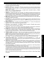
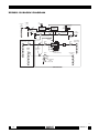
See next page for ZPR68-10 Block Diagram
SPECIFICATIONS
Amplifiers & Preamplifiers
AUDIO (ea. channel)
Gain (@ max VC*): ............................................................................................................................... Unity
Input Overload: .................................................................................................... > 4 V RMS (@ max VC*)
Input Impedance: ..................................................................................................................... > 40 k Ohms
Output Impedance: ...................................................................................................................... 470 Ohms
Signal to Noise: ................................................................................................................. 96 dB (re 2V out)
THD: (VC -10 dB) .................................................................................................... 0.01% at 2V input level
Frequency Response (± 3 dB): ............................................................................................. 5 Hz to 70 kHz
Bass Control Range (@ 100 Hz): ........................................................................... ± 12 dB (in 2 dB steps)
Treble Control Range (@ 10 kHz): ......................................................................... ± 12 dB (in 2 dB steps)
VIDEO
Input/Output Impedance: ............................................................................................................... 75 Ohms
Video Insertion Loss: ........................................................................................ < 1.0 dB (50 Hz to 10 MHz)
GENERAL
RC68 Code Group Number assigned to the ZPR68-10 ........................................................................... 68
Control (CO) & STATUS Outputs ............................ 12 V @ 10 mA, 9 V @ 90 mA (90 mA is max. current)
Max. Total Current Available From +12V, STATUS & CO Terminals .................................................. 1.8 A
Power Requirements: .......................................................... 14V-0-14V AC @ 2.7 A, 8V-0-8V AC @ 0.7 A
(Multi-Voltage Power supply included)
Gold Plated RCA type phono jacks ............................................................................ All A/V inputs/outputs
Dimensions: ............................................................................................................... 14" W x 7 " H x 2.5" D
Weight: ........................................................................................................................................ 4 lbs, 3 oz.
Note: *VC = Volume Control setting
ZPR68-10
15
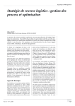
ZPR68-10 BLOCK DIAGRAM
Common
IR
Outputs
Common
IR
Level
HI
COM
PORT
LO
COMMON
CONTROL
1
2
3
4
5
6
7
8
Common
IR
Indicator
CO
G
+12V
GND
STATUS
IR IN
LOCAL
CONTROL
Zone Control
-IR Input
IR In
Common
CO Out
IR
Confirm
Zone
STATUS Out
Zone
IR Output
Zone IR
Indicator
Control
Data
Source Inputs
(Audio L & R)
Buffer
X1
1
Mute
Buffer
X 0.5
LMC1982
Buffer
LPF
Zone Outputs
(Audio L & R)
1
X2
2
2
3
4
5
6
7
8
Source
Inputs
(Video)
Source Input
Selectors
1
2
Buffer
3
X2
Treble
3
Bass
4
Level
(Volume & Balance)
2
3
5
7
Video Gain Adjust
Jumper
(0 dB, +3 dB)
4
5
6
8
SOURCE INPUTS PCB
6
1
4
6
5
Zone Outputs
(Video)
ZONE OUTPUTS PCB
2-2-00
16
ZPR68-10