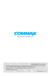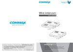
1
User Manual
VIDEO DOOR PHONE CAV-51M
513-11, Sangdaewon-dong, Jungwon-gu, Seongnam-si, Gyeonggi-do, Korea
Int’l Business Dept. : Tel.; +82-31-7393-540~550 Fax.; +82-31-745-2133
Web site : www.commax.com
Printed In Korea/ 2010.0 4.101
• Thank you for purchasing COMMAX products.
• Please carefully read this User’s Guide (in particular, precautions for safety) before using a product and follow
instructions to use a product exactly.
• The company is not responsible for any safety accidents caused by abnormal operation of the product.
Table of Contents
Warnings and caution
2
Features & Specifications
4
Part Name & Function
5
Multi Entry Panel Calling
6
Sub unit calling (Intercommunication)
6
Guard station or external area calling
6
Call/ Talk duration
7
Setting In-House unit as a Master and Sub Unite
7
Chime sound
8
Changing and initialization of the password
8
Opening the entrance of a Multi-entry Panel
With Password
9
Wiring
10
System diagrm
11
1
Warnings and caution
Make sure to follow the instructions to prevent any danger or property losses.
It indicates prohibition.
Warning
It indicates prohibition of disassembly.
Death or serious
injury is expected.
It indicates prohibition of contact.
It indicates dos and don’ts.
It indicates that the plug should be pulled out from the socket.
Warning
2
Do not put the plug in the socket
simultaneously.
It may generate abnormal heat
or cause a fire.
Do not connect to other products
while in use.
It may cause breakdown.
Do not forcibly bend the cord or
put a heavy object on the product.
It may cause a fire.
Do not use water, thinner or a detergent used to wash oil products when
you wash the exterior.
Make sure to wash it by using a dry cloth to
prevent any breakdown or electric shock.
Do not install the product in a
humid place.
It may cause an electric shock or
a fire.
Do not forcibly pull out the
cord from the socket.
If the cord is damaged, it may
cause a fire or an electric shock.
Do not put the plug in the socket with a wet hand.
It may cause an electric shock.
Do not disassemble, repair or
modify the product.
It may cause a fire, an electric shock
or an injury due to malfunction of the
product.
Do not use AC circuit breaker.
It may cause an electric shock.
Warnings and caution
It indicates prohibition.
Caution
It indicates prohibition of disassembly.
An injury or property
losses are expected
It indicates prohibition of contact.
It indicates dos and don’ts.
It indicates that the plug should be pulled out from the socket.
Caution
If the socket holes are larger
than normal, do not put the
plug.
It may cause an electric shock
or a fire.
Make sure that dust or foreign
substances are not gathered
on the product.
Make sure to prevent foreign
substances from entering the
product.
It may cause a breakdown.
Do not put a heavy object on
the product.
It may cause a breakdown.
Do not disassemble or give an
impact to the product.
Avoid direct rays of the sun or
heating devices at a time of
installation.
Install the product in a flat and
stable place.
Otherwise, it may not function
properly.
Pull the plug if the product is
not used for a long time.
If the product generates strange
sound, make sure to pull the
plug immediately and contact
Commax service center.
3
This is a DC type Color Video phone.
It can add up to a maximum of 2 sub-units in each residence and is a surface
mount type videophone that connects to a guard station or an external area.
Its functions include “Door release” and “Room-to-room” call.
1. Features
1. DC type Color video phone
2. When installing only 1 master unit, power is supplied from a Floor
Distributor without an additional power supply.
3. Sub-monitors need an extra power source.
4. 5”TFT LCD Monitor
5. 3 buttons : “Guard station call”, “Door release” and “Extension call”
6. COMMAX chime (Sol, Mi, Do) is the ring tone that sounds from Multi Entry
Panel. “Ding-Dong” sounds from an individual door when there is a call.
7. Door release
8. 6 wires UTP Cable (CAT.5) including a power source.
2. Specifications
ITEMS
CAV-51M
Wiring
Floor distributor: 6 wires(talk2, DATA1, POWER1, VIDEO1, GND1)
Power Voltage
DC24V~28V/ 5A (supplied from Floor Distributor) an extra power is required for Sub units
Transmission
Method
Screen
Dimension
Power
4
Full duplex
5” TFT LCD
Stand by : 60mA
requirements
Maximum operation : 500mA
Distance
range
Between Floor Distributor
and In-house uni
UTP (Ø0.5)
50m
3. Parts Names & Functions
No
Details
No
7
Details
1
Handset
Color Control
2
LCD Screen
8
Contrast Control
3
Extension call button and a Lamp
9
Video brightness control
4
Guard station call button and a Lamp
10
Call volume control
5
Door release button and a Power Lamp
11
Speaker
6
Power switch
This is an in-house unit that is a Color videophone.
Up to 4 residences are connectable with a single Floor distributor through
a Building Distributor connected with the Multi Entry Panel.
Each residence can add 2 sub-units, which comes to 3 units in total including
a master unit.
5
4. Multi Entry Panel Calling
1. When receiving a call from the Multi-Entry Panel, you will hear the COMMAX
chime and the image of the visitor will be shown on the screen
2. Pick up the handset to initiate conversation.
3. When opening the door of the Multi Entry Panel during a conversation,
Press the “Door release” button and the entrance will open.
(The call conversation is ended right after the release of the door)
4. When conversation is over, hang up the handset.
5. Sub unit calling (Intercommunication)
1. Pick up the handset and, press the “Extension call button” to make a call to the sub unit.
2. When the sub unit responds, conversation occurs.
(Calling both the Extension and Master unit is possible)
* When calling the Guard station with another unit or while talking with
the other Extension, another in-house unit cannot make a call.
3. While talking with another extension unit and an incoming call from the Multi-EntryPanel arrives, You have 30 seconds to answer the call from the Multi-Entry panel
by pressing the hook switch of CAV-51M once on the extension unit
(only one extension can have a conversation with Multi-Entry panel at a time)
6. Guard station or external area calling
1. Pick up the handset and press the “ Guard call ”button to call the Guard Station.
2. When the guard station responds, conversation can occurs.
* The Guard station unit does not have an outgoing calling function,
it can only receive calls)
* If the Guard unit is on the line with another residence or Multi entry unit,
you will hear a busy tone)
6
7. Call / Talk duration
This is applied to all calls and conversation.
1. Calling time lasts for 30 seconds.
2. Talking duration lasts for 60 seconds.
8. Setting In-House unit as a Master and Sub Units.
- This setting should be set by the Multi Entry Panel which should be
connected to channel 1
- When a single unit is installed, the setting should be set as a master unit.
(In case more than 2 units are installed, one should be set as a master, and the rest
should be set as slave units.)
- The “Door Release” and “Extension call” button on the unit run as a selection
to the master or slave in this mode.
1) Setting Master
1) Set the ID as “0” on the Multi Entry Panels that should be connected to channel 1.
- The default of all Multi Entry Panel is assigned to “0”
2) While picking up the handset of an in-house unit, press the “extension cal” button
and the “door release” button at the same time.
3) You can communicate with the Multi Entry Panel while the resident’s number
is displayed on it.
When the “✽✽✽->M” message is displayed on the Multi Entry Panel
when you press the “Door Open” button on an in-house unit.
4) Then, register the ID of the shown residence, and press “
” button to hear
a sound of completion.
5) The registration is complete when you hang up the handset.
(Repeat this process for other residences)
6) Set the ID as “1” on the multi-entry panel after completing the registration.
7
1) Setting Master
① Set the ID as“ 0”on Multi-Entry panel which shold be connected to chanel 1
- The default of all Multi Entry Panels is assigned to“0”.
② While picking up the handset of an in-house unit, press the
“extension call”button and the“door release”button at the same time.
③ You can communicate with the Multi Entry Panel while the resident’
s
number is displayed on it.
④ When the“*** -> M”message is displayed on the Multi Entry Panel
when you press the“Door Open”button on an in-house unit.
⑤ Then, register the ID of the shown residence,
and press“
”button to hear a sound of completion.
⑥ The registration is complete when you hang up the handset.
(Repeat this process for other residentes)
⑦ Set the ID’ as “1” on the Multi-Entry panel after completing the registration
9. Chime Sound
Chime will sound when calling an individual door bell with audio type .
10. Changing and initialization of the password.
Note) the doors do not open by default password “1234”
Only after changing default Password, can you use this function
1) Initialization for the password (only the password for the Master unit is initialized)
①
Shut off master unit and turn it on again while holding the “Extension call” button
and “Door release” button at the same time for 3 seconds.
②
The password will initialize to “1234” when the LCD stops blinking.
Note : Default password: 1234
2) Changing Resident Password
①
Hold “Residence Number” and “
“ button for 2 seconds and release
when LCD stops blinking.
8
②
Enter “ Current password”.
③
Hold “
④
Enter “New Password” with 4 digits on Multi Entry Panel displaying “NEW PW : “message.
⑤
Hold “Key
⑥
Repeat “New password” to confirm it.
⑦
Hold “
” button for 2 seconds and release when the LCD stops blinking.
” button for 2 seconds and release when the LCD stops blinking.
” button for 2 seconds and release when the LCD stops blinking.
11. Opening the entrance of a Multi-entry panel
with password
Note : The doors do not open by default password “1234”
Only after changing default Password, can you use this function.
1) Open the entrance with resident password.
①
Enter the resident number and “
” button
②
Enter the PIN number and the “
” button
The door opens with the “OPEN” message will be displayed on the LCD screen.
2) Open the entrance with Building password.
①
Enter “ 9900”and “
②
Enter the “ Building password “ and the “
” button
” button
The door opens with the “OPEN” message display on the LCD screen
9
12. Wiring and System diagram
1. Wiring
2. Wiring method
- Please pay attention to the polarity of the wires.
Units will not work properly when mis-wired.
- The Power of the Master unit is supplied from the Building distributor without
an additional power supply, but additional sub units requires a separate a power source.
(There is no power line connection between Master unit and Sub units)
10
3. Diagram
11
Memo
12