1
RAID Controller
User’s Manual
© 2007 GeoVision, Inc. All rights reserved.
The GeoVision logo and GV series products
are trademarks of GeoVision, Inc.
2007/03
English
DVRS-UM-2
Contents
Important Notice .................................................................................................... 1
1. Overview of RAID.............................................................................................. 3
1.1 Different RAID Levels ....................................................................................................3
1.1.1 RAID 0 ................................................................................................................................... 3
1.1.2 RAID 1 ................................................................................................................................... 4
1.1.3 RAID 1E ................................................................................................................................. 4
1.1.4 RAID 3 ................................................................................................................................... 5
1.1.5 RAID 5 ................................................................................................................................... 5
1.1.6 RAID 6 ................................................................................................................................... 6
1.1.7 Summary of RAID Levels....................................................................................................... 7
1.2 RAID Set ........................................................................................................................8
1.3 Volume Set ....................................................................................................................8
2. BIOS Configuration ........................................................................................... 9
2.1 Starting the RAID Configuration Utility ..........................................................................9
2.2 Configuring Raid Sets and Volume Sets.......................................................................11
2.3 Designating Drives as Hot Spares................................................................................11
2.4 Using Quick Volume /Raid Setup Configuration...........................................................12
3. Main Menu of BIOS Configuration................................................................ 13
3.1 Quick Volume/RAID Setup ...........................................................................................14
3.2 RAID Set Function .......................................................................................................18
3.2.1 Create RAID Set .................................................................................................................. 18
3.2.2 Delete RAID Set................................................................................................................... 20
3.2.3 Expand RAID Set ................................................................................................................. 20
3.2.4 Activate Incomplete RAID Set ............................................................................................. 22
3.2.5 Create Hot Spare ................................................................................................................. 22
3.2.6 Delete Hot Spare ................................................................................................................. 23
3.2.7 RAID Set Information .......................................................................................................... 23
3.3 Volume Set Function....................................................................................................24
3.3.1 Create Volume Set................................................................................................................ 24
3.3.2 Delete Volume Set ............................................................................................................... 29
3.3.3 Modify Volume Set............................................................................................................... 29
3.3.4 Check Volume Set................................................................................................................ 30
3.3.5 Stop Volume Set Check ....................................................................................................... 31
3.3.6 Display Volume Set Info. ..................................................................................................... 31
I
3.4 Physical Drives .............................................................................................................32
3.4.1 View Drive Information........................................................................................................ 32
3.4.2 Create Pass-Through Disk ................................................................................................... 32
3.4.3 Modify a Pass-Through Disk ................................................................................................ 33
3.4.4 Delete Pass-Through Disk ................................................................................................... 33
3.4.5 Identify Selected Drive ........................................................................................................ 34
3.5 RAID System Function .................................................................................................34
3.5.1 Mute The Alert Beeper ........................................................................................................ 34
3.5.2 Alert Beeper Setting ............................................................................................................ 35
3.5.3 Change Password ................................................................................................................ 35
3.5.4 JBOD/RAID Function ........................................................................................................... 36
3.5.5 Background Task Priority..................................................................................................... 36
3.5.6 Maximum SATA Mode.......................................................................................................... 37
3.5.7 HDD Read Ahead Cache ...................................................................................................... 37
3.5.8 Stagger Power On ............................................................................................................... 38
3.5.9 Empty HDD slot HDD........................................................................................................... 38
3.5.10 HDD SMART Status Polling................................................................................................ 38
3.5.11 Controller Fan Detection.................................................................................................... 39
3.5.12 Disk Write Cache Mode ..................................................................................................... 39
3.5.13 Capacity Truncation........................................................................................................... 40
3.6 View System Events.....................................................................................................40
3.7 Clear Events Buffer ......................................................................................................41
3.8 Hardware Monitor ........................................................................................................41
3.9 System Information .....................................................................................................41
4. Web-Based Configuration .............................................................................. 42
4.1 ArcHTTP Proxy Server Configurations..........................................................................44
4.1.1 General Configuration.......................................................................................................... 44
4.1.2 Mail Configuration................................................................................................................ 45
4.1.3 SNMP Trap Configuration .................................................................................................... 47
4.2 Web-Based RAID Configuration Utility.........................................................................49
5. Main Menu of Web-based Configuration..................................................... 51
5.1 Quick Function .............................................................................................................51
5.2 RAID Set Functions ......................................................................................................52
5.2.1 Create RAID Set .................................................................................................................. 52
5.2.2 Delete RAID Set................................................................................................................... 53
5.2.3 Expand RAID Set ................................................................................................................. 53
5.2.4 Activate Incomplete RAID Set ............................................................................................. 54
5.2.5 Create Hot Spare ................................................................................................................. 54
II
5.2.6 Delete Hot Spare ................................................................................................................. 55
5.2.7 Rescue RAID Set ................................................................................................................. 55
5.3 Volume Set Functions ..................................................................................................56
5.3.1 Create Volume Set............................................................................................................... 56
5.3.2 Delete Volume Set ............................................................................................................... 59
5.3.3 Modify Volume Set............................................................................................................... 59
5.3.4 Check Volume Set................................................................................................................ 60
5.3.5 Stop Volume Set Check ....................................................................................................... 61
5.4 Physical Drive...............................................................................................................61
5.4.1 Create Pass Through Disk ................................................................................................... 61
5.4.2 Modify Pass Through Disk ................................................................................................... 62
5.4.3 Delete Pass Through Disk.................................................................................................... 63
5.4.4 Identify Selected Drive ........................................................................................................ 63
5.5 System Controls...........................................................................................................64
5.5.1 System Config...................................................................................................................... 64
5.5.2 SNMP Configuration............................................................................................................. 66
5.5.3 View Events / Mute Beeper ................................................................................................. 67
5.5.4 Generate Test Event............................................................................................................ 68
5.5.5 Clear Events Buffer.............................................................................................................. 68
5.5.6 Modify Password.................................................................................................................. 68
5.5.7 Update Firmware ................................................................................................................. 69
5.6 Information..................................................................................................................70
5.6.1 RAID Set Hierarchy.............................................................................................................. 70
5.6.2 System Information ............................................................................................................. 70
5.6.3 Hardware Monitor................................................................................................................ 71
III
Important Notice
Before you start the RAID Controller to manage your hard disk drives, please pay attention to
the following notice.
Recommended Hard Drive
To avoid incompatibility between RAID Controller and hard disk drives, we strongly suggest
you use Seagate Barracuda® ES drives. For details on the drives, see Seagate’s website:
http://www.seagate.com/www/en-us/products/servers/barracuda_es/
The following is the available models of Barracuda® ES drives:
Model
Capacity
ST3250620NS
250GB
ST3320620NS
320GB
ST3400620NS
400GB
ST3500630NS
500GB
ST3750640NS
750GB
Begin with BIOS Configuration
The GV-DVR system provides two methods to configure RAID arrays:
•
BIOS Configuration
•
Web-Based Configuration
When building RAID for the first time, please use BIOS configuration only. If you use the
web-based configuration, RAID build will fail. Later you can use the web-based configuration
to manage the RAID Controller system.
For details on the BIOS configuration, see Chapter 2 and 3. For details on the web-based
configuration, see Chapter 4 and 5.
1
Order of Hard Drive Slots
Remember the order of hard drive slots on the GV-DVR System. When there is a warning
message or buzzer on the failed hard drive, follow these procedures:
1. Check which hard disk failed from “Raid Set Hierarchy” of the web-based
configuration page.
2. Remove the failed one in the correct slot.
Warning: If you remove the hard drive in the wrong slot, you could suffer data loss.
•
Raid Set Hierarchy:
In \ Information \ RaidSet Hierarchy, you can view the status of each hard drive. In this
figure, Ch05 (hard drive No. 5) failed.
•
The order of hard drive slots:
1
4
5
2
3
6
7
8
2
1
Overview of RAID
1. Overview of RAID
RAID is an acronym of Redundant Array of Independent Disks. It is an array of multiple
independent hard disk drives that provides high performance and fault tolerance.
The RAID Controller provides non-stop service with a high degree of fault tolerance through
the use of RAID technology. It also features advanced array management. It makes the RAID
implementation and disks’ physical configuration transparent to the host operating system,
meaning the system drivers and software utilities are not affected, regardless of the RAID
level selected.
1.1 Different RAID Levels
RAID Levels are a series of configurations of RAID. Each level has its way of connecting the
hard drives, writing and retrieving data. The descriptions below introduce some commonly
used RAID Levels.
1.1.1 RAID 0
Also referred to as striping, RAID 0 writes stripes of data across multiple disk drives. RAID 0
does not support fault tolerance and redundancy, but performs fast in writing and reading
data. RAID 0 breaks up data into smaller blocks and then writes a block to each drive in the
array. Disk striping enhances performance because multiple drives are accessed
simultaneously. With the lack of redundancy, RAID 0 is less reliable because the entire array
fails when any one disk drive fails.
3
1.1.2 RAID 1
RAID 1 is also known as disk mirroring. Data written to one disk drive is simultaneously
written to another disk drive. Read performance may be enhanced if the array controller can,
in parallel, access both members of a mirrored pair. The write performance is not highly
effective in comparison of writing data to a single disk. If one drive fails, all data (and
software applications) are preserved on the other drive. RAID 1 offers extremely high data
reliability, which demands a high cost of data storage capacity.
1.1.3 RAID 1E
RAID 1E is a combination of RAID 0 and RAID 1, combing stripping with disk mirroring. RAID
level 10 combines the fast performance of Level 0 with the dada redundancy of Level 1. In
this configuration, data is distributed across several disk drives, similar to Level 0, which are
then duplicated to another set of drive for data protection. RAID 1E has been traditionally
implemented using an even number of disks, some hybrids can use an odd number of disks
as well.
The graph below is an example of a hybrid RAID 1E array comprised of five disks: A, B, C, D
and E. Each stripe is mirrored on an adjacent disk with wrap-around. When the number of
disks comprising a RAID 1E is even, the striping pattern is identical to that of a traditional
RAID 1E, with each disk being mirrored by exactly one other unique disk. Therefore, all the
characteristics for a traditional RAID 1E apply to a RAID 1E when the latter has an even
number of disks.
4
1
Overview of RAID
1.1.4 RAID 3
RAID 3 provides disk striping and complete data redundancy to a dedicated parity drive.
RAID 3 breaks up data into smaller blocks, calculates parity by performing an exclusive or on
the blocks, and then writes the blocks to all but one drive in the array. The parity data created
during the exclusive or is then written to the last drive in the array. If a single drive fails, data
is still available by computing the exclusive or of the contents corresponding stripes of the
surviving member disk. RAID 3 is best for applications that require very fast data – transfer
rates or long data blocks.
1.1.5 RAID 5
RAID 5 is sometimes called striping with parity at byte level. In RAID 5, the parity information
is written to all of the drives in the controllers rather than being concentrated on a dedicated
parity disk. If one drive in the system fails, the parity information can be used to reconstruct
the data from that drive. All drives in the array system can be used to seek operations at the
5
same time, greatly increasing the performance of the RAID system. This is also the primary
reason that RAID 5 is more often implemented in RAID arrays.
1.1.6 RAID 6
Similar to RAID 5, RAID 6 performs two different parity computations or the same
computation on overlapping subsets of the data. RAID 6 offers greater fault tolerance but
only consumes the capacity of 2 disk drives for distributed parity scheme. Data is striped on a
block level across a set of drives, and then a second set of parity is calculated and written
across all of the drives.
6
1
Overview of RAID
1.1.7 Summary of RAID Levels
Features and Performance
RAID
Level
0
1
1E
3
5
6
Description
Also known as striping
Data distributed across
multiple drives in the array.
There is no data protection.
Also known as mirroring
All data replicated on N
separated disks. N is almost
always 2.
This is a high availability
solution, but due to the 100%
duplication, it is also a costly
solution.
Half of drive capacity in array
are devoted to mirroring.
Also known as BlockInterleaved Parity
Data and parity information
are subdivided and distributed
across all disks.
Parity must be equal to the
smallest disk capacity in the
array. Parity information
normally stored on a dedicated
parity disk.
Also known as BitInterleaved Parity.
Data and parity information
are subdivided and distributed
across all disks.
Parity data consumes the
capacity of 1 disk drive.
Parity information normally
stored on a dedicated parity
disk.
Also known as BlockInterleaved Distributed Parity.
Data and parity information
are subdivided and distributed
across all disks.
Parity data consumes the
capacity of 2 disk drives.
RAID 6 provides the highest
reliability.
Similar to RAID 5, but does
two different parity
computations.
RAID 6 offers fault tolerance
greater than RAID 1 or RAID 4.
Parity data consumes the
capacity of 2 disk drives.
Min.
Drives
Data
Reliability
Data
Transfer Rate
1
No data
protection
Very high
Lower than
RAID 6
Reads are
higher than a
single disk.
Reads are
twice as fast as
a single disk.
Writes are
similar to a
single disk.
Writes are
similar to a
single disk.
Transfer rates
are more similar
to those of RAID
1 than RAID 0.
Reads are
twice as fast as
a single disk.
2
Higher than
RAID 3 and 5
Lower than
RAID 6
3
3
3
Higher than
RAID 3 and 5
Reads are
similar to RAID
0
Higher than
a single drive
Writes are
slower than a
single disk
Higher than
a single drive
Highest
reliability
4
Very high for
both Reads
and Writes
Writes are
similar to a
single disk.
Lower than
RAID 1, 1E
and 6
Lower than
RAID 1, 1E
and 6
I/O
Request Rate
Reads are
close to being
twice as fast as
single disk
Writes are
similar to a
single disk
Reads are
similar to
RAID 0.
Reads are
similar to
RAID 0.
Writes are
slower than a
single disk.
Reads are
similar to
RAID 0.
Writes are
slower than a
single disk.
Reads are
similar to
RAID 0.
Writes are
slower than a
single disk.
Writes are
slower than a
single disk.
7
1.2 RAID Set
A RAID set is a group of disks connected to a RAID controller. A RAID set contains one or
more volume sets. The RAID set itself does not define the RAID level; the RAID level is
defined within each volume set. So, volume sets are contained within RAID sets and the
RAID level is defined within the volume set. If physical disks of different capacities are
grouped together in a RAID set, then the capacity of the smallest disk will become the
effective capacity of all the disks in the RAID set.
1.3 Volume Set
Each volume set is seen by the host system as a single logical device (i.e., a single large
virtual hard disk). A volume set will use a specific RAID level, which will require one or more
physical disks (depending on the RAID level used). RAID level refers to the level of
performance and data protection of a volume set. The capacity of a volume set can consume
all or a portion of the available disk capacity in a RAID Set. Multiple volume sets can exist in
a RAID Set.
For the RAID Controller, a volume set must be created either on an exiting RAID Set or on a
group of available individual disks (that will become part of a RAID Set). If there are preexisting RAID Sets with available capacity and enough disks for the desired RAID Level, then
the volume set can be created in the existing RAID set of the user’s choice.
8
2
BIOS Configuration
2. BIOS Configuration
The RAID Configuration Utility is BIOS based and is used to configure RAID sets and
volume sets. Because the utility resides in the RAID Controller firmware, operation is
independent of any operating systems on your computer. This utility can be used to:
Create RAID sets,
Expand RAID sets
Add physical drives,
Define volume sets,
Modify volume sets,
Modify RAID level/stripe size,
Define pass-through disk drives,
Modify system functions, and
Designate drives as hot spares.
2.1 Starting the RAID Configuration Utility
This section explains how to use the RAID Configuration Utility to configure your RAID
system. The RAID Configuration Utility is designed to be user-friendly. It is a menu-driven
program, residing in the firmware, which allows you to scroll through various menus and
submenus and select among the predetermined configuration options.
9
To start the RAID configuration, follow these steps:
1. Turn on the GV-DVR system. It will display the following message on the monitor during
the startup sequence (after the system BIOS startup screen but before the operating
system boots).
PCI-X RAID Controller – DRAM: 128 (MB) / #Channels: 8
BIOS V1.17b / Date: 2006-08-07 – F/W: V1.42 / Date: 2006-10-13
f Bus / Dev / Func = 4/14/0, I/O-Port: FDBFF000h, IRQ = 10, BIOS= CC00: 0h
fff No BIOS disk found. RAID controller BIOS not installed!
fff Press <Tab/F6> to enter SETUP menu. 5 second(s) left <ESC to Skip>
2. Press TAB or F6 to start the RAID Configuration window. Note the message only
remains on your screen for five seconds, and then it will enter the main screen of the GVDVR system.
3. The RAID Configuration window appears and shows a dialog box listing the SATA RAID
Controller that is installed in the system. Press Enter to enter the main menu.
10
2
BIOS Configuration
4. To verify password, type the default value Admin.
2.2 Configuring Raid Sets and Volume Sets
With RAID Configuration Utility you can configure RAID sets and volume sets automatically
using Quick Volume/Raid Setup or manually using Raid Set/Volume Set Function. Each
configuration method requires a different level of user input. Generally, configuring RAID sets
and volume sets proceed as follows:
Step Action
1
Designate hot spares/pass-through drives (optional).
2
Choose a configuration method.
3
Create RAID sets using the available physical drives.
4
Define volume sets using the space available in the RAID Set.
5
Initialize the volume sets and use Volume Sets (as logical drives) in the host OS.
2.3 Designating Drives as Hot Spares
Any unused disk drive that is not part of a RAID set can be designated as a hot spare. The
Quick Volume/RAID Setup configuration will add the spare disk drive and automatically
display the appropriate RAID level from which the user can select. For the RAID Set
Function Configuration option, you can use the Create Hot Spare option to define the hot
spare disk drive.
11
When a hot spare disk drive is being created by the Create Hot Spare option (in the RAID
Set Function), all unused physical devices connected to the current controller appear:
Choose the target disk by selecting the appropriate check box. Press the ENTER key to
select a disk drive, and press Yes in the Create Hot Spare to designate it as a hot spare.
2.4 Using Quick Volume /Raid Setup Configuration
Quick Volume / RAID Setup Configuration collects all available drives and includes them in a
RAID set. The RAID set you created is associated with exactly one volume set. You will only
be able to modify the default RAID level, the stripe size, and the capacity of the new volume
set. Designating drives as Hot Spares is also possible in the raid level selection option. The
Volume Set default settings will be:
Parameter
Volume Name
SCSI Channel/SCSI
ID/SCSI LUN
Cache Mode
Tag Queuing
Setting
Volume Set # 00
0/0/0
Write Back
Yes
The default setting values can be changed after configuration is complete. Follow the steps
below to create arrays using the RAID Set / Volume Set method:
Step Action
1
Choose Quick Volume /Raid Setup from the main menu. The available
RAID levels with hot spare for the current volume set drive are displayed.
2
It is recommended that your drives of the same capacity be put in a specific array. If
you use drives with different capacities in an array, all drives in the raid set will be
set to the capacity of the smallest drive in the raid set. The numbers of physical
drives in a specific array determines which RAID levels that can be implemented in
the array. RAID 0 requires 1 or more physical drives. RAID 1 requires at least 2
physical drives. RAID 1+Spare requires at least 3 physical drives. RAID (1+0)
requires at least 4 physical drives. RAID 3 requires at least 3 physical drives. RAID
5 requires at least 3 physical drives. RAID 3 +Spare requires at least 4 physical
drives. RAID 5 + Spare requires at least 4 physical drives. RAID 6 requires at least
4 physical drives. RAID 6 + Spare requires at least 5 physical drives. Highlight the
desired RAID level for the volume set and press the ENTER key to confirm.
3
The capacity for the current volume set is entered after highlighting the desired
RAID level and pressing the ENTER key. The capacity for the current volume set is
displayed. Use the UP and DOWN arrow keys to set the capacity of the volume set
and press the ENTER key to confirm. The available stripe sizes for the current
volume set are then displayed.
12
2
BIOS Configuration
4
Use the UP and DOWN arrow keys to select the current volume set stripe size and
press the ENTER key to confirm. This parameter specifies the size of the stripes
written to each disk in a RAID 0, 1, 5 or 6 Volume Set. You can set the stripe size to
4 KB, 8 KB, 16 KB, 32 KB, 64 KB, or 128 KB. A larger stripe size provides better
read performance, especially when the computer performs mostly sequential reads.
However, if the computer performs random read requests more often, choose a
smaller stripe size.
5
When you are finished defining the volume set, press the ENTER key to confirm the
Quick Volume And Raid Set Setup function.
6
Foreground (Fast Completion) Press the ENTER key to define fast initialization or
Selected the Background (Instant Available). In the background Initialization, the
initialization proceeds as a background task, the volume set is fully accessible for
system reads and writes. The operating system can instantly access to the newly
created arrays without requiring a reboot and waiting the initialization complete. In
Fast Initialization, the initialization proceeds must be completed before the volume
set ready for system accesses.
7
Initialize the volume set you have just configured.
8
If you need to add additional volume set, using main menu Create Volume Set
function.
Note: A user can use this method to examine the existing configuration. The “modify
volume set configuration” method provides the same functions as the “create volume set
configuration” method. In the volume set function, you can use “modify volume set” to
change all volume set parameters except for capacity (size).
3. Main Menu of BIOS Configuration
The main menu shows all functions that are available for executing actions, which is
accomplished by clicking on the appropriate link.
Note: The manufacture default password is set to ADMIN; this password can be modified
by selecting Change Password in the RAID System Function section.
13
Option
Description
Quick Volume/RAID Setup
Create a default configuration based on the number of
physical disk installed
RAID Set Function
Create a customized RAID set
Volume Set Function
Create a customized volume set
Physical Drives
View individual disk information
RAID System Function
Setup the RAID system configuration
Ethernet Configuration
Feature not available
View System Events
Record all system events in the buffer
Clear Event Buffer
Clear all information in the event buffer
Hardware Monitor
Show the hardware system environment status
3.1 Quick Volume/RAID Setup
“Quick Volume/RAID Setup” is the fastest way to prepare a RAID set and a volume set. It
requires only a few keystrokes to complete. Although disk drives of different capacity may be
used in the RAID set, it will use the capacity of the smallest disk drive as the capacity of all
disk drives in the RAID set. The Quick Volume/ RAID Setup option creates a RAID set with
the following properties:
14
3
Main Menu of BIOS Configuration
• All of the physical drives are contained in one RAID set.
• The RAID level, hot spare, capacity, and stripe size options are selected during the
configuration process.
• When a single volume set is created, it can consume all or a portion of the available disk
capacity in this RAID set.
• If you need to add an additional volume set, use the “Create Volume Set” option in main
menu.
The total numbers of physical drives in a specific RAID set determine the RAID levels that
can be implemented within the RAID set. Select Quick Volume/RAID Setup from the main
menu; all possible RAID levels will be displayed on the screen.
If the volume capacity exceeds 2 TB, the controller will show the “Greater 2 TB Volume
Support” sub-menu.
15
No: It keeps the volume size with max. 2 TB limitation.
Use 64bit LBA: This option CAN NOT work on the GV-DVR System, because this
option works on different OS that supports 16 bytes CDB.
For Windows: It changes the sector size from default 512 Bytes to 4 K Bytes. The
maximum volume capacity is up to 16 TB.
This option works under Windows platform only. And it CAN NOT be converted to
Dynamic Disk, because 4k sector size is not a standard format.
A single volume set is created and consumes all or a portion of the disk capacity available in
this RAID set. Define the capacity of volume set in the Available Capacity popup. The default
value for the volume set, which is 100% of the available capacity, is displayed in the selected
capacity. To enter a value less than the available capacity, use UP and DOWN arrow keys to
select the specific capacity and press the ENTER key to accept this value. If the volume set
uses only part of the RAID set capacity, you can use the Create Volume Set option in the
main menu to define additional volume sets.
Stripe size
This parameter sets the size of the stripe written to each disk in a RAID 0, 1, 5, or 6 logical
drive. You can set the stripe size to 4 KB, 8 KB, 16 KB, 32 KB, 64 KB, or 128 KB. A larger
stripe size produces better-read performance, especially if your computer does mostly
sequential reads. However, if you are sure that your computer performs random reads more
often, select a smaller stripe size.
16
3
Main Menu of BIOS Configuration
Select Yes in the Create Vol/RAID Set dialog box, the RAID set and volume set will start to
initialize.
Select Foreground (Faster Completion) or Background (Instant Available) for
initialization.
17
3.2 RAID Set Function
Manual configuration gives complete control of the RAID set setting, but it will take longer to
configure than “Quick Volume/RAID Setup”. Select RAID Set Function to manually configure
the RAID set for the first time, or delete existing RAID sets and reconfigure the RAID set.
3.2.1 Create RAID Set
To define a RAID set, follow these steps:
1. Select RAID Set Function from the main menu.
2. Select Create RAID Set. A Select SATA Drive For RAID Set window appears, showing
the SATA drives connected to the current controller.
18
3
Main Menu of BIOS Configuration
3. Press the UP ARROW and DOWN ARROW keys to select specific physical drives. Press
the ENTER key to associate the selected physical drive with the current RAID set.
Repeat this step; the user can add as many disk drives as are available to a single RAID
set.
4. When you finish selecting SATA drives for RAID set, press the ESC key. A Create RAID
Set confirmation screen appears, select Yes to confirm it.
5. The Edit The RAID Set Name dialog box appears, enter 1 to 15 alphanumeric characters
to define a unique identifier for the RAID set. The default RAID set name will always
appear as “RAID Set. #”.
19
3.2.2 Delete RAID Set
To completely erase and reconfigure a RAID set, you must first delete it and re-create the
RAID set.
To delete a RAID set, select the RAID set number that the user wants to delete in the Select
RAID Set to Delete screen. When the Delete RAID Set dialog box appears, press Yes key to
delete it.
Warning: Data on the RAID set will be lost if this option is used.
3.2.3 Expand RAID Set
Instead of deleting a RAID set and recreating it with additional disk drives, the Expand RAID
Set function allows the user to add disk drives to the RAID set that has already been created.
To expand a RAID set, follow these steps:
1. Select the Expand RAID Set option. If there is an available disk, the Select SATA Drives
For RAID Set Expansion screen will appear.
2. Select the target RAID set by clicking on the appropriate radio button. Select the target
disk by selecting the appropriate check box.
3. Press Yes to start expansion of the RAID set.
20
3
Main Menu of BIOS Configuration
The new additional capacity can be utilized by one or more volume sets. Follow the
instruction presented in the Volume Set Function to modify the volume sets; operation
system specific utilities may be required to expand operating system partitions.
Note:
1. Once the Expand RAID Set process has started, the user cannot stop it. The process
must be completed.
2. If a disk drive fails during RAID set expansion and a hot spare is available, an auto
rebuild operation will occur after the RAID set expansion completes.
Migrating
Migration occurs when a disk is added to a RAID set. Migration status is displayed in the
RAID Set information screen when a disk is being added to a RAID set. Migrating status is
also displayed in the associated Volume State area of the Volume Set Information screen
when a disk is added to a RAID set.
21
3.2.4 Activate Incomplete RAID Set
When one of the disk drives is removed in power off state, the RAID State will change to
Incomplete State. If a user wants to continue to work while the RAID Controller is powered on,
the user can use the Activate RAID Set option to activate the RAID set. After the user selects
this function, the RAID State will change to Degraded Mode.
3.2.5 Create Hot Spare
The Create Hot Spare option allows you to define a global hot spare. When you choose this
option in the RAID Set Function, all unused physical devices connected to the current
controller will appear. To create a hot spare, follow these steps:
To create a hot spare, select the target disk by selecting the appropriate check box. Press
the ENTER key to select a disk drive, and press Yes to designate it as a hot spare.
22
3
Main Menu of BIOS Configuration
3.2.6 Delete Hot Spare
To delete a hot spare, select the target hot spare disk to delete by selecting the appropriate
check box. Press the ENTER key to select a disk drive, and press Yes to delete the hot
spare.
]
3.2.7 RAID Set Information
To display RAID Set information, select the desired RAID Set number, and press the ENTER
key. The RAID Set Information will display. You can only view the information of the RIAD set
in this screen, not modify it.
23
3.3 Volume Set Function
A volume set is seen by the host system as a single logical device; it is organized in a RAID
level within the controller utilizing one or more physical disks. RAID level refers to the level of
data performance and protection of a volume set. A volume set can consume all of the
capacity or a portion of the available disk capacity of a RAID set. Multiple volume sets can
exist on a RAID set. If multiple volume sets reside on a specified RAID Set, all volume sets
will reside on all physical disks in the RAID set. Thus each volume set on the RAID set will
have its data spread evenly across all the disks in the RAID set rather than one volume set
using some of the available disks and another volume set using other disks.
3.3.1 Create Volume Set
The Create Volume Set option creates a volume set with the following properties:
Volume sets of different RAID levels may coexist on the same RAID set.
Up to 16 volume sets in a RAID set can be created by the SATA RAID controller.
The maximum addressable size of a single volume set is not limited to 2 TB as with other
cards that support only 32-bit mode.
To create a volume set, follow these steps:
1. Select Volume Set Function from the main menu.
2. Select Create Volume Set, and press the ENTER key. The Create Volume From RAID
Set dialog box appears. This screen displays the existing arranged RAID sets.
3. Select the RAID set number, and press the ENTER key. The “Volume Creation” dialog
box appears. This screen displays a summary of the current volume set’s settings.
24
3
Main Menu of BIOS Configuration
4. You can modify the default values of the volume name, capacity, RAID level, stripe size,
disk info, cache mode and tag queuing.
5. After completing the modification of the volume set, press the ESC key to confirm it. The
“Initialization Mode” dialog box appears.
6. Select Foreground (Faster Completion) for faster initialization of the selected volume
set. Select Background (Instant Available) for normal initialization of the selected
volume set.
7. Repeat Steps 3 to 6 to create additional volume sets.
8. The initialization percentage of volume set will be displayed at the button line.
Volume Name
The default volume name will always appear as “Volume Set #”. You can rename the volume
set providing it does not exceed the limit of 15 characters.
25
RAID Level
Set the RAID level for the volume set. Highlight RAID Level and press the ENTER key. The
available RAID levels for the current volume set will appear. Select a RAID level and press
the ENTER key to confirm.
Capacity
The maximum available volume size is the default value for the first setting. Enter the
appropriate volume size to fit your application. The capacity value can be increased or
decreased by the UP and DOWN arrow keys. The capacity of each volume set must be less
than or equal to the total capacity of the RAID set on which it resides.
If the volume capacity exceeds 2 TB, the controller will show the “Greater 2 TB Volume
Support” sub-menu. Select No to keep the volume size with the limitation of 2 TB. Or select
For Windows to have the volume capacity up to 16 TB. Refer to the same sub-menu in 3.1
Quick Volume/RAID Setup.
26
3
Main Menu of BIOS Configuration
Stripe Size
This parameter sets the size of the segment written to each disk in a RAID 0, 1, 5, or 6
logical drive. You can set the stripe size to 4 KB, 8 KB, 16 KB, 32 KB, 64 KB, or 128 KB.
SCSI Channel / SCSI ID / SCSI LUN
Keep the default values in these three options.
SCSI Channel: The RAID Controller function simulates a SCSI RAID controller. The host
bus represents the SCSI channel.
SCSI ID: Each device attached to the SATA card, as well as the card itself, must be
assigned a unique SCSI ID number. A SCSI channel can connect up to 15 devices.
SCSI LUN: Each SCSI ID can support up to 8 LUNs. Most SCSI controllers treat each
LUN as if it were a SCSI disk.
27
Cache Mode
The user can set the cache mode to either Write-Through or Write-Back.
Tag Queuing
This option, when enabled, can enhance overall system performance under multi-tasking
operating systems. The Command Tag (Drive Channel) function controls the SCSI command
tag queuing support for each drive channel. This function should normally remain enabled.
Disable this function only when using older drives that do not support command tag queuing.
28
3
Main Menu of BIOS Configuration
3.3.2 Delete Volume Set
To delete a volume set, follow these steps:
1. Select Volume Set Function from the main menu.
2. Select Delete Volume Set, and press the ENTER key. All RAID Set # items appear.
3. Select a RAID Set number, and press the ENTER key. All Volume Sets within that RAID
set appear.
4. Select the Volume Set number that is to be deleted, and press the ENTER key to delete it.
3.3.3 Modify Volume Set
To modify a volume set, follow these steps:
1. Select Volume Set Function from the main menu.
2. Select Modify Volume Set, and press the ENTER key. All RAID Set # items appear.
3. Select a RAID Set number, and press the ENTER key. All Volume Set items within that
RAID set appear.
4. Select the Volume Set that is to be changed, and press the ENTER key.
5. The properties of the selected Volume Set appear. All values can be modified except the
capacity.
29
3.3.4 Check Volume Set
Use this option to verify the correctness of the redundant data in a volume set. For example,
in a system with a dedicated parity disk drive, a volume set check entails computing the
parity of the data disk drives and comparing those results to the contents of the dedicated
parity disk drive. To check the volume set, follow these steps:
1. Select Volume Set Function from the main menu.
2. Select Check Volume Set, and press the ENTER key. All RAID Set # items appear.
3. Select a RAID Set number, and press the ENTER key. All Volume Set items within that
RAID set appear.
4. Select the Volume Set that is to be checked, and press the ENTER key to start the check.
30
3
Main Menu of BIOS Configuration
3.3.5 Stop Volume Set Check
Use this option to stop all of the Check Volume Set operations.
3.3.6 Display Volume Set Info.
To display Volume Set information, follow these steps:
1. Select the desired Volume Set number and then press the ENTER key.
2. The Volume Set Information will be shown. You can only view the information of this
Volume Set on this screen, not modify it.
31
3.4 Physical Drives
Choose this option from the main menu to select a physical disk and perform the operations
listed above.
3.4.1 View Drive Information
When you choose this option, the physical disks connected the SATA RAID controllers are
listed. Select the desired drive and press the ENTER key to view drive information.
3.4.2 Create Pass-Through Disk
A Pass-Through Disk is not controlled by the SATA RAID Controller firmware and thus
cannot be a part of a volume set. The disk is available directly to the operating system as an
individual disk. It is typically used on a system where the operating system is on a disk not
controlled by the SATA RAID Controller firmware. The SCSI Channel, SCSI ID, SCSI LUN,
Cache Mode, and Tag Queuing must be specified to create a pass-through disk.
32
3
Main Menu of BIOS Configuration
3.4.3 Modify a Pass-Through Disk
To modify a pass-through disk from the pool of pass-through disks, follow these steps:
1. Select Physical Drive from the main menu.
2. Select Modify Pass-Through Drive, and press the ENTER key. All RAID Pass-Through
Drive number options appear.
3. Select the desired item, and press the ENTER key. The Pass-Through Attribute appears.
4. Select the parameter from the list to be change, and press the ENTER key to modify it.
3.4.4 Delete Pass-Through Disk
To delete a Pass-through drive from the Pass-through drive pool, select Physical Drive from
the main menu, select Delete Pass-Through Drive, and then press the ENTER key. The
Delete Pass-Through confirmation screen will appear; select Yes to delete it.
33
3.4.5 Identify Selected Drive
To prevent removing the wrong drive, the selected disk HDD LED Indicator will light for
physically locating the selected disk when the Identify Selected Device is selected.
This feature is not available on the GV-DVR system.
3.5 RAID System Function
Select this option from the main menu to set the RAID system functions.
3.5.1 Mute The Alert Beeper
The Mute Alert Beeper option is used to control the RAID Controller beeper.
Select Yes and press the ENTER key in the dialog box to turn the beeper off temporarily.
The beeper will still activate on the next event.
34
3
Main Menu of BIOS Configuration
3.5.2 Alert Beeper Setting
The Alert Beeper function is used to disable or enable the RAID Controller alarm tone
generator. Select Disabled and press the ENTER key in the dialog box to turn the beeper off.
3.5.3 Change Password
The manufacturer default password is set to ADMIN. The password option allows the
user to set or clear the password protection feature. Once the password has been set, the
user can monitor and configure the controller only by providing the correct password. The
Controller will check the password only when entering the main menu from the initial screen.
The system will automatically go back to the initial screen if it does not receive any command
in 20 seconds.
To set or change the password, select RAID System Function and press Change
Password. The Enter New Password screen will appear.
To disable the password, only press the ENTER key in both the “Enter New Password”
and “Re-Enter New Password” column. The existing password will be cleared. No
password checking will occur when entering the main menu.
35
3.5.4 JBOD/RAID Function
JBOD is an acronym of Just a Bunch Of Disks. It represents a volume set that is created by
the concatenation of partitions on the disk. The operating system can see all disks when the
JBOD option is selected. It is necessary to delete any RAID set(s) on any disk(s) if switching
from a RAID to a JBOD configuration.
3.5.5 Background Task Priority
The “Background Task Priority” is a relative indication of how much time the controller
devotes to a rebuild operation. The RAID Controller allows the user to choose the rebuild
priority (ultralow, low, normal, high) to balance volume set access and rebuild tasks
appropriately.
36
3
Main Menu of BIOS Configuration
3.5.6 Maximum SATA Mode
The Controller can support up to SATA ll, which runs up to 300MB/s, twice as fast as
SATA150. NCQ is a command protocol in Serial ATA that can only be implemented on native
Serial ATA hard drives. It allows multiple commands to be outstanding within a drive at the
same time. Drives that support NCQ have an internal queue where outstanding commands
can be dynamically rescheduled or re-ordered, along with the necessary tracking
mechanisms for outstanding and completed portions of the workload.
3.5.7 HDD Read Ahead Cache
Allow Read Ahead—When Enabled, the drive’s read ahead cache algorithm is used,
providing maximum performance under most circumstances. This function is enabled by
default.
37
3.5.8 Stagger Power On
In a PC system with only one or two drives, the power can supply enough power to spin up
both drives simultaneously. But in systems with more than two drives, the startup current
from spinning up the drives all at once can overload the power supply, causing damage to
the power supply, disk drives and other system components. This damage can be avoided by
allowing the host to stagger the spin-up of the drives. New SATA drives have support
staggered spin-up capabilities to boost reliability.
The RAID Controller has included the option for the user to select the value for staggered
power up. The value can be selected from 0.4ms to 6ms per step that powers up one drive.
3.5.9 Empty HDD slot HDD
The Empty HDD Slot HDD option is to set up the Failed LED light ON or OFF. When each
slot has a power LED for the HDD installed identify, the user can set this option to OFF.
Choose this option ON, the failed LED light will flash red light if no HDD installed.
This feature is not available on the GV-DVR system.
3.5.10 HDD SMART Status Polling
An external RAID enclosure has the hardware monitor in the dedicated backplane that can
report HDD temperature status to the controller. However, PCI cards do not use backplanes
if the drives are internal to the main server chassis. The type of enclosure cannot report the
HDD temperature to the controller.
38
3
Main Menu of BIOS Configuration
For this reason, HDD SMART Status Polling was added to enable scanning of the HDD
temperature function. It is necessary to enable the HDD SMART Status Polling function
before SMART information is accessible. This function is disabled by default.
3.5.11 Controller Fan Detection
This function is not available on the GV-DVR system.
3.5.12 Disk Write Cache Mode
The user can set the “Disk Write Cache Mode” to Auto, Enabled, or Disabled. Enabled
increases speed, and Disabled increases reliability.
39
3.5.13 Capacity Truncation
The RAID Controller uses drive truncation so that drives from different vendors are more
likely to be usable as spares for one another. Drive truncation slightly decreases the usable
capacity of a drive that is used in redundant units. The Controller provides three truncation
modes in the system configuration: Multiples Of 10G, Multiples Of 1G, and No Truncation.
Multiples Of 10G: If you have 120 GB drives from different vendors, chances are that the
capacity varies slightly. For example, one drive might be 122.5 GB, and the other 120 GB.
The drive truncation mode Multiples Of 10G uses the same capacity for both of these
drives so that one could replace the other.
Multiples Of 1G: If you have 123 GB drives from different vendors, chances are that the
capacity varies slightly. For example, one drive might be 122.5 GB, and the other 122.4
GB. The drive truncation mode Multiples Of 1G uses the same capacity for both of these
drives so that one could replace the other.
No Truncation: It does not truncate the capacity. Within the subsystem, the SCSI chip
acts as a target and 5 SATA ll buses are connected to the drive.
3.6 View System Events
Choose this option to view the system events information: Timer, Device, Event type,
Elapsed Time, and Errors. The RAID system does not have a real time clock. The Time
information is the relative time from the RAID Controller powered on.
40
3
Main Menu of BIOS Configuration
3.7 Clear Events Buffer
Use this feature to clear the entire events buffer.
3.8 Hardware Monitor
Choose this option to view the RAID Controller’s hardware monitor information. The
Hardware Information screen appears. The Hardware Monitor Information provides the
temperature and fan speed (I/O Processor fan) of the RAID Controller.
For this feature, you have to enable the HDD SMART Status Polling function first.
3.9 System Information
Choose this option to display Main processor, CPU Instruction cache and data cache size,
firmware version, serial number, controller model name, and the cache memory size.
41
4. Web-Based Configuration
The ArcHTTP Proxy Server starts at system startup, allowing you to configure RAID arrays,
Mail alerts and SNMP alerts via the browser.
Note: For the first time usage, do not configure hard drives by the web-based utility;
otherwise the RAID configuration will fail. Use the BIOS-based configuration utility instead.
The Server provides you with two options:
•
Controller#01(PCI): To enter the configuration page of RAID Controller, highlight the
item, and then click Start. For more information, see 4.2 Web-Based RAID
Configuration Utility.
•
Cfg Assistant: To enter the configuration page of ArcHTTP Proxy Server, highlight the
item, and then click Start. For more information, see 4.1 ArcHTTP Proxy Server
Configurations.
Caution:
•
The GV-desktop mode is designed without system tray, so please do not “minimize” the
ArcHTTP dialog box. Otherwise you cannot call it up again.
•
After you “close” the ArcHTTP dialog box, please click the Programs button on the GVDesktop and then select RAID Controller to bring it up again.
42
4
Web-Based Configuration
Access Options on GV-Desktop
To access configuration pages easily, direct links are also provided on the GV-Desktop.
On the GV-Desktop, click the Programs button and select the following options to the
desired configuration page:
• RAID Controller: Brings up the ArcHTTP dialog box.
• RAID Console: Links to the web-based RAID configuration page. See 4.2 Web-Based
RAID Configuration Utility.
• RAID Mail Alert Configuration: Links to the Mail Configuration page. See 4.1.2 Mail
Configuration.
Note: If you have modified the default blind IP 127.0.0.1 of ArcHTTP Proxy Server, the links
“RAID Console” and “RAID Mail Alert Configuration” will be invalid. For blind IP setting, see
4.1.1 General Configuration.
43
4.1 ArcHTTP Proxy Server Configurations
To enter the configuration page of ArcHTTP Proxy Server, highlight Cfg Assistant on the
ArcHTTP dialog box, and then click Start.
The ArcHTTP Proxy Server configurations include General Configuration, Mail
Configuration and SNMP Trap Configuration.
4.1.1 General Configuration
On the General Configurations page, you can change the basic settings of the Server.
Binding IP: This item shows the current IP address of the Server. The default blinding IP
is 127.0.0.1.
HTTP Port#: You can change the default HTTP ports 81 and 82. By default the RAID
Controller configuration page is set to 81, and the Server configuration page is 82. The
port you assign here will be picked up by the RAID Controller configuration page; the
Server will pick up the next number as HTTP port. (e.g. you enter port 1000 for the RAID
configuration page; port 1001 will be picked up by the Server configuration page.)
Note: If your GV-DVR system is behind a firewall, make sure the default ports 81 and 82 are
open; otherwise, you cannot configure the Server and RAID Controller.
Display HTTP Connection Information To Console: The default setting is No.
Scanning PCI Device: Not available.
Scanning RS-232: Not available.
Scanning Inband Device: Not available.
After the changes are made, select the Confirm The Operation check box and click Submit.
44
4
Web-Based Configuration
4.1.2 Mail Configuration
You can configure the mail server to send system notifications for the remote administrator.
Click Mail Configuration from the menu. This page appears.
SMTP Server Configurations: Type the IP address of SMTP server.
Mail Address Configurations: Type the sender name and sender e-mail address that
will be shown in the outgoing e-mails. Type the account and password if the SMTP
needs, and type the receiver’s e-mail address and name.
Event Notification Configurations: The controller classifies disk array events into four
levels depending on their severity. These include level 1: Urgent, level 2: Serious, level 3:
Warning and level 4: Information. The level 4 covers notification events such as
initialization of the controller and initiation of the rebuilding process; Level 3 includes
events which require the issuance of warning messages; Level 2 covers notification
events which once have happen; Level 1 is the highest level, and covers events the
need immediate attention (and action) from the administrator. The following charts list
examples of different types of events.
45
Charts of Event Notification
A. Device Event
Event
Level
Meaning
Device Inserted
Warning
HDD inserted
Device Removed
Warning
HDD removed
Reading Error
Warning
HDD reading error
Writing Error
Warning
HDD writing error
ATA Ecc Error
Warning
HDD ECC error
Action
Keep Watching HDD status,
maybe it is caused by noise
or HDD unstable.
Keep Watching HDD status,
maybe it is caused by noise
or HDD unstable.
Keep Watching HDD status,
maybe it is caused by noise
or HDD unstable.
Change ATA Mode Warning
HDD change ATA mode
Check HDD connection.
Time Out Error
Warning
HDD Time out
Keep Watching HDD status,
maybe it is caused by noise
or HDD unstable.
Device Failed
Urgent
HDD failure
Replace HDD
Serious
PCI Parity error
If only happen once, it maybe
caused by noise. If always
happen, please check power
supply or contact to us.
Urgent
HDD SMART failure
Replace HDD
PCI Parity Error
Device Failed
(SMART)
Pass Through
Disk Created
Pass Through
Disk Modified
Pass Through
Disk Deleted
Inform
Inform
Inform
Pass Through Disk
Created
Pass Through Disk
Modified
Pass Through Disk
Deleted
B. Volume Event
Event
Level
Start Initialize
Warning
Start Rebuilding
Warning
Start Migrating
Warning
Start Checking
Warning
Complete Init
Warning
Complete Rebuild
Warning
Complete Migrate
Warning
46
Meaning
Volume initialization has
started
Volume rebuilding has
started
Volume migration has
started
Volume parity checking
has started
Volume initialization
completed
Volume rebuilding
completed
Volume migration
Action
4
Web-Based Configuration
Complete Check
Warning
Create Volume
Delete Volume
Warning
Warning
completed
Volume parity checking
completed
New Volume Created
Volume deleted
Modify Volume
Warning
Volume Modified
Volume Degraded
Urgent
Volume degraded
Volume Failed
Urgent
Volume failure
Failed Volume
Revived
Urgent
Failed Volume revived
Event
Level
Meaning
Create RaidSet
Warning
New Raidset created
Delete RaidSet
Warning
Raidset deleted
Expand RaidSet
Warning
Raidset expanded
Rebuild RaidSet
Warning
Raidset rebuilding
RaidSet Degraded
Urgent
Raidset degraded
Replace HDD
Event
Level
Meaning
Action
DRAM 1-Bit ECC
Urgent
DRAM 1-Bit ECC error.
Check DRAM
DRAM Fatal Error
Urgent
DRAM fatal error
encountered.
Check the DRAM module and
replace with new one if
required.
Raid Powered On
Warning
Raid Power On
Test Event
Urgent
Test Event
Replace HDD
C. RAID Set Event
Action
D. Hardware Event
4.1.3 SNMP Trap Configuration
You can configure SNMP to send system notification for the remote administrator. To
configure the SNMP function, click SNMP Trap Configuration. This page appears.
47
SNMP Trap Configurations: Enter the SNMP Trap IP Address.
SNMP System Configurations: Community name acts as a password to screen
accesses to the SNMP agent of a particular network device. Type the community names
of the SNMP agent. Before access is granted to a request station, this station must
incorporate a valid community name into its request; otherwise, the SNMP agent will
deny access to the system. Most network devices use “public” as default of their
community names. This value is case-sensitive.
SNMP Trap Notification Configurations: The SNMP Trap Notification Configurations
include level 1: serious, level 2: error, level 3: Warning and level 4: Information. The level
4 covers notification events such as initialization of the controller and initiation of the
rebuilding process; Level 3 includes events which require the issuance of warning
messages; Level 2 covers notification events which once have happen; Level 1 is the
highest level, and covers events the need immediate attention (and action) from the
administrator. You can refer to “Charts of Event Notification” above for examples of
events.
48
4
Web-Based Configuration
4.2 Web-Based RAID Configuration Utility
To enter the configuration page of RAID Controller, highlight Controller#01(PCI) on the
ArchHTTP dialog box, and then click Start.
It will pop up a dialog box for authentication.
User name: admin
Password: admin
The web-based RAID Configuration utility displays the current configuration of your RAID
Controller. It displays the RAID Set List, Volume Set List, and Physical Disk List. The
current configuration can also be viewed by clicking on RaidSet Hierarchy in the menu. See
5.6.1 RaidSet Hierarchy.
•
RAID Set Hierarchy
• RAID Set Information
To display RAID set information, select the desired RAID set number. The RAID set
information will be displayed.
49
• Volume Set Information
To display volume set information, select the desired Volume Set number. The volume set
Information will be displayed.
• Drive Information
To display drive information, select the desired physical drive number. The drive Information
will be displayed.
50
5
Main Menu of Web-Based Configuration
5. Main Menu of Web-based Configuration
The Main Menu shows all available functions.
Individual Category
Description
Quick Function
Create a default configuration, which is based on the number of
physical disks installed; it can modify the volume set capacity,
RAID level, and stripe size.
RAID Set Functions
Create a customized RAID set.
Volume Set Functions
Create customized volume sets and modify the existed volume
sets parameter.
Physical Drives
Create pass through disks and modify the existing pass through
drives parameters. Also provides the function to identify disk
drives (blinking LED).
System Controls
Set the RAID system configuration.
Information
View the controller information. The RAID set hierarchy can be
viewed with the RaidSet Hierarchy option.
Note: The login user name and password by default is admin.
5.1 Quick Function
The number of physical drives in the RAID Controller determines the RAID levels that can be
implemented with the RAID set. You can create a RAID set associated with exactly one
volume set. Click Quick Function and select Quick Create. This page appears.
You can change the RAID level, stripe size, and capacity. A hot spare option is also created
depending on the existing configuration. Select the Confirm The Operation check box and
click Submit. The RAID set and volume set will start to initialize.
51
Note:
1. In Quick Create, your volume set is automatically configured based on the number of
disks in your system. Use the Raid Set Function and Volume Set Function if you
prefer to customize your system.
2. If volume capacity exceeds 2TB, the utility will show the “Greater 2 TB volume Support”
item. Select For Windows from the drop-down list. DO NOT select Use 64 bit LBA
that will not work on the GV-DVR system.
5.2 RAID Set Functions
Use the RAID Set Function and Volume Set Function if you prefer to customize your system.
Manual configuration can provide full control of the RAID set settings, but it will take longer
time to complete than the Quick Volume / RAID Setup configuration. Select RAID Set
Functions to manually configure the raid set for the first time or delete and reconfigure
existing raid sets. (A RAID set is a group of disks containing one or more volume sets.)
5.2.1 Create RAID Set
To create a RAID set, select Create RAID Set. This page appears.
It shows the drive(s) connected to the current controller. Select the physical drives within the
current RAID set. Enter 1 to 15 alphanumeric characters to define a unique identifier for a
RAID set. The default RAID set name will always appear as “Raid Set. #”. Select the
Confirm The Operation check box and click Submit. The RAID set will start to initialize.
52
5
Main Menu of Web-Based Configuration
5.2.2 Delete RAID Set
To delete a RAID set, select Delete RAID Set. This page appears.
It shows all existing RAID sets in the current controller. Select the RAID set number you
want to delete and select the Confirm The Operation check box, and then click Submit to
delete it.
5.2.3 Expand RAID Set
When a disk is added to your system, you can expand a RAID set. This function becomes
active when at least one drive is available.
To expand a RAID set, select Expand Raid Set. This page appears.
Select the RAID set to be expanded. Select the disk and the Confirm The Operation check
box, and then click Submit.
53
5.2.4 Activate Incomplete RAID Set
If one of the disk drives is removed when power is off, the RAID set state will change to
“Incomplete State.” If you want to continue to power-on the SATA RAID controller, you can
use the Activate RAID Set option to active the RAID set. After you complete this procedure,
the Raid State will change to “Degraded Mode”.
To activate the incomplete RAID, select Activate Raid Set. This page appears.
It shows the RAID sets existing on the current controller. Select the RAID set to activate in
the select column. Click Submit to activate the RAID set that had a disk removed (or failed)
in the power off state. The SATA RAID controller will continue to work in degraded mode.
5.2.5 Create Hot Spare
The Create Hot Spare option allows you to define a global hot spare. All unused physical
devices connected to the current controller display on the “Select The IDE Drives For Hot
Spare” page.
54
5
Main Menu of Web-Based Configuration
Select the disks, select the Confirm The Operation check box, and click Submit to create
the hot spares.
5.2.6 Delete Hot Spare
To delete a hot spare drive, select Delete Hot Spare. This page appears.
Select the Hot Spare disk, select the Confirm The Operation check box and then click
Submit to delete the hot spare.
5.2.7 Rescue RAID Set
When the system is powered off in the RAID set update / creation period, the RAID
configurations possibly could disappear due to this abnormal condition.
55
The “RESCUE” function can recover the missing RAID set information. The RAID Controller
uses the time as the RAID set signature. The RAID set may have different time after the
RAID set is recovered. The “SIGANT” function can regenerate the signature for the RAID set.
5.3 Volume Set Functions
A volume set is seen by the host system as a single logical device. It is organized in a RAID
level with one or more physical disks. RAID level refers to the level of data performance and
protection of a volume set. A volume set capacity can consume all or a portion of the disk
capacity available in a RAID set. Multiple volume sets can exist on a group of disks in a
RAID set. Additional volume sets created in a specified RAID set will reside on all the
physical disks in the RAID set. Thus each volume set on the RAID set will have its data
spread evenly across all the disks in the RAID set.
5.3.1 Create Volume Set
1. Volume sets of different RAID levels may coexist on the same RAID set.
2. Up to 16 volume sets can be created by the RAID Controller.
3. The maximum addressable size of a single volume set is not limited to 2 TB because the
controller is capable of 64-bit mode.
To create a volume set on a RAID set, click Create Volume Set. The “Select The Raid Set
To Create Volume On It” page shows all RAID set numbers. Select the RAID set number
that is to be used and then click Submit.
56
5
Main Menu of Web-Based Configuration
This option allows you to select the volume name, capacity, RAID level, stripe size, SCSI
ID/LUN, cache mode, and tag queuing.
• Volume Name
The default volume name will always appear as “Volume Set. #”. You can rename the
volume set providing it does not exceed the 15 characters limit.
• RAID Level
Set the RAID level for the Volume Set. Highlight the desired Raid Level and press the
ENTER key.
The available RAID levels for the current Volume Set are displayed. Select a RAID level
and press the ENTER key to confirm.
57
• Capacity
The maximum volume size is the default initial setting. Enter the appropriate volume size
to fit your application.
• Greater Two TB Support
If volume capacity exceeds 2TB, this item appears. Select For Windows from the dropdown list. Do not select Use 64bit LBA since this selection does not work on the GVDVR system.
• Initialization Mode
Press the Enter key to define fast initialization or select the Background (Instant
Available). When Background Initialization begins, the initialization proceeds as a
background task, the volume set is fully accessible for system reads and writes. The
operating system can instantly access to the newly created arrays without requiring a
reboot and waiting the initialization complete. When Fast Initialization begins, the
initialization proceeds must be completed before the volume set ready for system
accesses.
• Stripe Size
This parameter sets the size of the stripe written to each disk in a RAID 0, 1, RAID 1E, 5
or 6 logical drives. You can set the stripe size to 4 KB, 8 KB, 16 KB, 32 KB, 64 KB, or
128 KB. A larger stripe size produces better read performance, especially if your
computer does mostly sequential reads. However, if your computer does random reads
more often, select a smaller stripe size.
Note: RAID level 3 can’t modify stripe size.
• Cache Mode
The SATA RAID controller supports Write-Through Cache and Write-Back Cache.
• Tag Queuing
Enabling this option is useful for enhancing overall system performance in multi-task
operating systems. The Command Tag (Drive Channel) function controls the SCSI
command tag queuing support for each drive channel. This function should normally
remain enabled. Disable this function only when using older SCSI drives that do not
support command tag queuing
• SCSI Channel/SCSI ID/SCSI Lun
SCSI Channel: The SATA RAID controller function is simulated as a SCSI RAID
controller. The host bus is represented as a SCSI channel. Select the SCSI Channel.
58
5
Main Menu of Web-Based Configuration
SCSI ID: Each SCSI device attached to the SCSI card, as well as the card itself, must
be assigned a unique SCSI ID number. A SCSI channel can connect up to 15 devices.
The SATA RAID Controller is a large SCSI device. Assign an ID from a list of SCSI
IDs.
SCSI LUN: Each SCSI ID can support up to 8 LUNs. Most SCSI controllers treat
each LUN like a SCSI disk.
5.3.2 Delete Volume Set
To delete a Volume from RAID set, select Delete Volume Set. This page appears.
The “Select The Volume Set To Delete” page shows all RAID set numbers. Select a RAID
set number and the Confirm The Operation check box, and then click Submit to show all
volume set items in the selected RAID set. Select a volume set number, select the Confirm
The Operation check box, and then click Submit to delete the volume set.
5.3.3 Modify Volume Set
Use this option to modify the volume set configuration. To modify volume set attributes, click
Volume Set Functions and then select Modify Volume Set. The “Select The Volume Set
For Modification” page appears.
59
Select the volume set check box from the list that you wish to modify, and then click Submit.
This page appears.
All values can be modified except Max Capacity Allowed. After you complete the
modification, select the Confirm The Operation check box and click Submit.
5.3.4 Check Volume Set
Use this option to verify the correctness of the redundant data in a volume set. For example,
in a system with dedicated parity, volume set check means computing the parity of the data
disk drives and comparing the results to the contents of the dedicated parity disk drive. The
RaidSet Hierarchy option in the menu of Information also displays the information about
checking percentage.
To check a volume set from a RAID set, select Check Volume Set. This page appears.
Select the volume set from the list that you wish to check, select the Confirm The Operation
check box, and then click Submit.
60
5
Main Menu of Web-Based Configuration
5.3.5 Stop Volume Set Check
To stop checking volume consistency, select Stop Volume Set Check, select the Confirm
The Operation check box, and then click Submit.
5.4 Physical Drive
Choose this option to select a physical disk from the Main Menu and then perform the
operations listed below.
5.4.1 Create Pass Through Disk
To create a pass-through disk, select Create Pass Through. This page appears.
61
A pass-through disk is not controlled by the SATA RAID controller firmware; it cannot be a
part of a volume set. The disk is available to the operating system as an individual disk. It is
typically used on a system where the operating system is on a disk not controlled by the
RAID firmware. You can also select the Volume Cache Mode (Write Back / Write Through),
enable or disable Tagged Command Queuing, and set SCSI channel/SCSI_ID/SCSI_LUN
for this volume.
5.4.2 Modify Pass Through Disk
This function is used to modify the Pass-Through Disk attribute. You can modify the cache
mode, Tagged Command Queuing, and SCSI channel/ID/LUN on an existing pass through
disk. To modify the pass-through drive attribute from the pass-through drive pool, select
Modify Pass Through. The “Select The Pass Through Disk For Modification” page appears.
Select Pass-Through disk from the pass-through drive pool and click Submit. When the
“Enter Pass-Through Disk Attribute” page appears, modify the drive attribute values.
After you finish the selection, select the Confirm The Operation check box and click Submit
to complete the modification.
62
5
Main Menu of Web-Based Configuration
5.4.3 Delete Pass Through Disk
To delete a pass-through drive from the pass-through drive pool, select Delete Pass
Through.
After you complete the selection, select the Confirm The Operation check box and click
Submit to delete the disk.
5.4.4 Identify Selected Drive
To prevent removal of the wrong drive, the selected disk LED will light so as to physically
locate the intended disk when Identify Selected Drive is selected.
This feature is not available on the GV-DVR system.
63
5.5 System Controls
5.5.1 System Config
To set the RAID system function, click System Controls and then select System Config.
The ”System Configurations” page appears.
• System Beeper Setting
Use the drop-down list to select Enabled or Disabled to control the SATA RAID controller
alarm tone generator.
• Background Task Priority
The Raid Rebuild Priority indicates how much time the controller devotes to a rebuild
operation. The SATA RAID controller allows you to choose the rebuild priority to balance
volume set access and rebuild tasks appropriately. The priority options include ultraLow
(5%), Low (20%), Normal (50%) and High (80%). For high array performance, select
Low (20%).
• JBOD/RAID Configuration
JBOD is an acronym for “Just a Bunch Of Disks”. It represents a volume set that is
created by the concatenation of partitions on the disk. The OS can see all disks when
this option is selected. It is necessary to delete a RAID set if the disks in that set are to
be converted to JBOD mode.
64
5
Main Menu of Web-Based Configuration
• Max SATA Mode Supported
The Controller can support up to SATA ll, which runs up to 300MB/s. NCQ is a command
protocol in Serial ATA that can only be implemented on native Serial ATA hard drives. It
allows multiple commands to be outstanding within a drive at the same time. Drives that
support NCQ have an internal queue where outstanding commands can be dynamically
rescheduled or re-ordered, along with the necessary tracking mechanisms for
outstanding and completed portions of the workload. The RAID system allows you to
choose the following SATA Mode (listed from slowest to fastest): SATA150,
SATA150+NCQ, SATA300, SATA300+NCQ.
• HDD Read Ahead Cache
When Read Ahead is enabled (set Enabled at default), the drive’s read ahead cache
algorithm is used, providing maximum performance under most circumstances.
• Stagger Power On Control
In a PC with only one or two drives, the power supply can provide enough power to spin
up both drives simultaneously. But in systems with more than two drives, the startup
current from spinning up the drives all at once can overload the power supply, causing
damage to the power supply, disk drives and other system components. However,
allowing the host to stagger the spin-up of the drives can avoid the damage.
New SATA drives support staggered spin-up capabilities to boost reliability. Staggered
spin-up is a very useful feature for managing multiple disk drives in a storage subsystem.
It gives the host the ability to spin up the disk drives sequentially or in groups, allowing
the drives to come ready at the optimum time without straining the system power supply.
Staggering drive spin-up in a multiple drive environment also avoids the extra cost of a
power supply designed to meet short-term startup power demand as well as steady state
conditions.
The RAID Controller has included the option for customer to select the disk drives
sequentially stagger power up value. The values can be selected from 0.4ms to 6ms per
step which powers up one drive.
• Empty HDD Slot LED (Not Available)
When each slot has a power LED for the HDD installed to identify, you can set this option
to OFF. Select ON, the failed LED light will flash red light; if no HDD installed.
• HDD SMART Status Polling
An external RAID enclosure has the hardware monitor in the dedicated backplane that
can report HDD temperature status to the controller. However, PCI cards do not use
65
backplanes if the drives are internal to the main server chassis. The type of enclosure
cannot report the HDD temperature to the controller.
For this reason, HDD SMART Status Polling is designed to enable scanning of the HDD
temperature function. It is necessary to enable the HDD SMART Status Polling function
before SMART information is accessible. This function is disabled by default.
• Disk Write Cache Mode
Use the drop-down list to select Auto, Enabled, or Disabled to set the mode.
• Disk Capacity Truncation Mode
The RAID controller uses drive truncation so that drives from differing vendors are more
likely to be able to be used as spares for each other. Drive truncation slightly decreases
the usable capacity of a drive that is used in redundant units.
The controller provides three truncation modes in the system configuration: Multiples Of
10G, Multiples Of 1G, and No Truncation.
Multiples Of 10G: If you have 120 GB drives from different vendors; chances are
that the capacity varies slightly. For example, one drive might be 122.5 GB, and
the other 120 GB. The drive at Truncation mode Multiples Of 10G uses the same
capacity for both of these drives so that one could replace the other.
Multiples Of 1G: If you have 123 GB drives from different vendors; chances are
that the capacity varies slightly. For example, one drive might be 122.5 GB, and
the other 122.4 GB. The drive at Truncation mode Multiples Of 1G uses the same
capacity for both of these drives so that one could replace the other.
No Truncation: It does not truncate the capacity.
5.5.2 SNMP Configuration
Select SNMP Configuration, this page appears.
Note: The SNMP configuration will not work on this page. For configurations, please see
4.1.3 SNMP Trap Configuration.
66
5
Main Menu of Web-Based Configuration
5.5.3 View Events / Mute Beeper
To view the RAID Controller’s information, select View Events/Mute Beeper. This page
appears.
It displays the system events information: Time, Device, Event Type, Elapse Time and
Errors.
The RAID system does not have a built-in real time clock. The information about Time
displayed here is synchronized with the time of the system.
67
5.5.4 Generate Test Event
To generate events for testing purposes, select Generate Test Event, select the Confirm
The Operation check box, and then click Submit.
5.5.5 Clear Events Buffer
To clear the entire events buffer information, select Clear Event Buffer, select the Confirm
The Operation check box, and then click Submit.
5.5.6 Modify Password
This option allows you to set or clear the RAID Controller’s password protection feature.
Once the password is set, you can only monitor and configure the RAID Controller with the
correct password. To set or change the RAID Controller password, click Modify Password.
The “Modify System Password” page appears.
68
5
Main Menu of Web-Based Configuration
The default password is admin. The password is used to protect the RAID Controller from
unauthorized entry. The Controller will check the password only when entering the Main
Menu from the initial screen. The RAID Controller will automatically go back to the initial
screen when it does not receive any command in ten seconds. To disable the password,
leave the fields blank. Once you confirm the modification, the existing password will be
cleared. Then, no password checking will occur when entering the main menu.
5.5.7 Update Firmware
GeoVision will periodically release the updated firmware.
To update the firmware, follow these steps:
1. Click System Controls and select Upgrade Firmware. This page appears.
2. Click Browse... to locate the firmware file (.bin) saved at your system.
3. Select the Confirm The Operation check box and then click Submit to start the
upgrade.
69
4. After the firmware upgrade is complete, a bar indicator shows “Firmware Has Been
Updated Successfully.”
5. Restart the controller or computer for the new firmware to take effect.
5.6 Information
5.6.1 RAID Set Hierarchy
To view the RAID Controller current RAID set, current volume set and physical disk
configuration, click Information and select RaidSet Hierarchy. This page appears.
5.6.2 System Information
To view the SATA RAID controller’s information, including name, firmware version, serial
number, main processor, CPU data/Instruction cache size and system memory size/ speed,
click Information and select System Information. The “RAID Subsystem Information” page
appears.
70
5
Main Menu of Web-Based Configuration
5.6.3 Hardware Monitor
To view the RAID controller’s hardware monitor information, click Information and select
Hardware Monitor. The “Hardware Monitor Information” page appears.
The Hardware Monitor Information provides the temperature, and fan speed (I/O Processor
fan) of the RAID Controller.
71


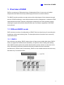
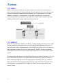
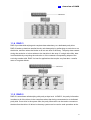
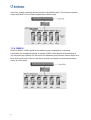

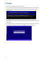
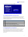
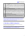
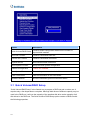
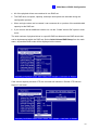
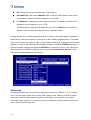
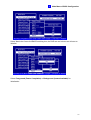

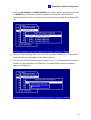

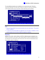
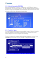
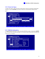
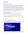

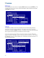
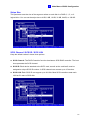


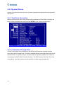
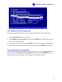
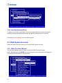
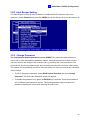
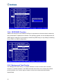
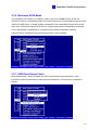
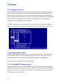
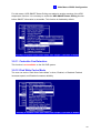
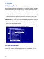
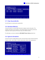
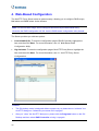
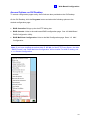
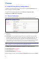
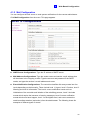
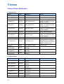
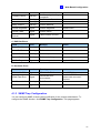
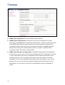
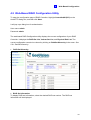
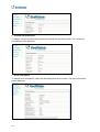
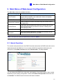
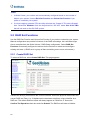
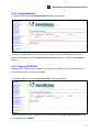
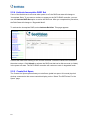

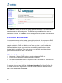
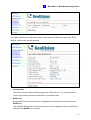
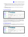


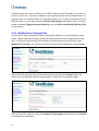
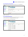
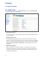
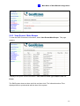
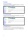
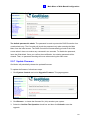

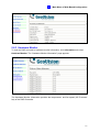
![Manual del usuario - [ [ [ ANSEL ] ] ]](http://vs1.manualzilla.com/store/data/006306298_1-4b727a9f513ab88544573091f86e1211-150x150.png)