1
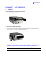
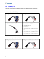
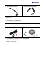
GV-Compact DVR V2
Quick Guide
Contents
Chapter 1
Introduction ........................................................................................................1
1.1
Models ......................................................................................................................1
1.2
Packing List ..............................................................................................................2
Chapter 2
Physical Description ..........................................................................................4
2.1
Front Panel ...............................................................................................................4
2.2
Rear Panel................................................................................................................5
2.3
Remote Control ........................................................................................................6
Chapter 3
3.1
Getting Started....................................................................................................8
Basic Connection......................................................................................................8
3.1.1
Connecting Vehicle Power Supply .................................................................9
3.1.2
Connecting Optional Video Output Devices ................................................. 11
3.2
Installing Hard Drive ...............................................................................................12
3.3
Turning On / Off the Power.....................................................................................14
3.3.1
Turning On the Power ..................................................................................14
3.3.2
Turning Off the Power ..................................................................................14
3.4
Formatting Hard Drive ............................................................................................15
3.5
Main Screen Overview ...........................................................................................16
3.6
Basic Operation ......................................................................................................17
3.6.1
Date/Time Adjustment ..................................................................................17
3.6.2
Recording Operation ....................................................................................17
3.6.3
Search/Playback Operation..........................................................................18
3.6.4
PTZ Operation..............................................................................................18
Chapter 4
4.1
4.2
Remote Viewing Using A Web Browser .........................................................19
Assigning an IP Address.........................................................................................19
4.1.1
Using OSD Menu .........................................................................................19
4.1.2
Connecting with a PC...................................................................................20
Accessing Your Surveillance Images......................................................................21
0Chapter 5
The I/O Terminal Block.....................................................................................22
1
Introduction
Chapter 1 Introduction
1.1 Models
The GV-Compact DVR V2 has the following models:
•
Standard Model (GV-LX4C2)
•
Anti-Vibration Model (GV-LX4C2V)
The GV-Compact DVR V2, equipped with vibration absorbers, can withstand severe
levels of shock and vibration in mobile environments.
Caution: The standard and anti-vibration models have different internal designs. It is
forbidden to connect the standard model to the vehicle power supply.
Note: The hard disk is not included in the packing list.
1
1.2 Packing List
If any of the items are missing or damaged, contact your dealer to arrange a replacement.
•
Standard Model (GV-LX4C2)
•
D-Type Video Cable x 1
•
D-Type Audio/TV/Spot Monitor Cable x 1
•
1 to 4 Camera Power Cable x 1
•
Power Adaptor 12V, 5.0A x 1
•
AC Power Cord x 1
•
Lock Key x 2
•
GV-Compact DVR V2 Remote Control
x1
•
Anti-Vibration Model (GV-LX4C2V)
•
D-Type Video Cable x 1
2
•
GV-Compact DVR V2 Software DVD x 1
•
GV-Compact DVR V2 User’s Manual x 1
•
D-Type Audio/TV/Spot Monitor Cable x 1
1
•
1 to 4 Camera Power Cable x 1
•
Lock Key x 2
•
GV-Compact DVR V2 Remote Control x 1
•
GV-Compact DVR V2 Software DVD x 1
•
GV-Compact DVR V2 User’s Manual x 1
•
Introduction
Cigarette Lighter Power Adapter x 1
The optional accessories contain the following items:
•
External IR Receiver
•
•
Power Adaptor 12V, 5.0A (Optional for Anti-Vibration Model)
•
AC Power Cord 110-125V, 10A (Optional for Anti-Vibration Model)
•
2.5” to 3.5” HDD Converter
GV-GPS 232 Receiver
3
Chapter 2
Physical Description
This section identifies the various components of the GV-Compact DVR V2, and provides the
overview of the remote control.
2.1 Front Panel
Figure 2-1
No. Name
Description
The two USB ports can connect the USB storage device,
Wireless LAN adaptor and/or mobile Internet device.
• Power LED: Turns on when the power is supplied.
• Ready LED: Turns on when the unit is ready for use.
• SATA LED: Turns on when the HDD is reading or
writing data.
• Disk Full LED: Turns on when the HDD is full.
1
USB Port
2
System LED
3
IR Receiver
Receives data from the infrared remote control.
4
Reset Button
Reboots the unit, and keeps all current configurations.
5
Default Button
Sets all configurations to their factory settings.
6
Storage Removal Button
Stops recording and removes the HDD from the system. If
the unit is installed in a vehicle, ensure to press the button
before turning off the ignition to protect the recorded data.
7
HDD Drive Bay
Installs the SATA hard drive for recording.
8
HDD Power LED
Turns on when the power is supplied.
9
Key Lock
Locks and unlocks the HDD drive bay.
10
HDD Activity LED
Blinks when the HDD is reading or writing data.
4
2
Physical Description
2.2 Rear Panel
Figure 2-2
No. Name
Description
1
DC Power Input (12V)
Connects to power supply.
2
External IR Receiver Port
Connects to the optional External IR Receiver.
3
75 Ω
When using the Loop function, please switch to Off. The
default setting is On.
•
4
Video In/Out
•
•
•
5
Audio/TV In/Out
•
•
Inputs (4 Blue Connectors/CH1-4): Connects to
cameras.
Outputs (4 Black Connectors/CH1-4): Loops out
each camera input to monitors.
TV Output (1 Black Connector/QUAD): Connects
to a TV monitor.
Spot Monitor Output (1 Black Connector/MUX):
Connects to a spot monitor to display video
sequentially from each video input.
Audio Inputs (4 White Connectors/MIC1-4):
Connects to microphones.
Audio Output for playback (1 Red Connector/
SPK-OUT): Connects to speakers. Note the audio
output only works during playback or when
receiving callback audio.
6
VGA Monitor Port
Connects to a PC monitor.
7
LAN Port
Connects to the network.
8
I/O Terminal Block
Connects to input and output devices, PTZ cameras,
GPS module and etc.
5
2.3 Remote Control
The GV-Compact DVR V2 Remote Control is provided to configure and operate the
GV-Compact DVR V2.
Figure 2-3
Button
Description
Stops recording.
Starts recording.
OSD menu: Moves the focus upward to the desired item.
Playback: Decreases the speed of playback.
OSD menu: Moves the focus downward to the desired item.
Playback: Stops playback.
OSD menu: Moves the focus leftward to the desired item; moves to the
previous page.
Playback: Plays the video backward at different speeds (2x, 4x, 8x, 16x and
32x).
OSD menu: Moves the focus rightward to the desired item; moves to the
next page.
Playback: Plays the video forward at different speeds (2x, 4x, 8x, 16x and
32x).
6
2
Physical Description
OSD menu: Enters the menu option and confirms the selection.
Playback: Plays or pauses video.
Switches to Channel 1 or I/O device 1.
Switches to Channel 2 or I/O device 2.
Switches to Channel 3 or I/O device 3.
Switches to Channel 4 or I/O device 4.
Switches to the screen of 4 divisions.
Zooms in or out.
Calls up the menu of SEARCH/PLAYBACK.
Confirms the menu selection.
Calls up the main menu.
Quits the menu selection or exits the menu.
A/B/C
Device Type
Switches the device type for the control of GV-Compact DVR V2.
7
Chapter 3 Getting Started
Getting started with the GV-Compact DVR V2 consists of the following steps:
3.1 Basic Connection
The following instructions describe the basic connection to the GV-Compact DVR V2.
Figure 3-1
1. Connect power. Using the supplied power adaptor, connect to the power.
2. Connect video input. Using the blue connectors of the supplied D-Type Video Cable,
connect to cameras.
3. Connect audio input and output. Using the supplied D-Type Audio/TV/Spot Monitor Cable,
connect to microphones and a speaker. Connect microphones to the four white
connectors of the cable, and a speaker to the red connector.
4. Connect video output. There are two options:
•
Using the black connector (QUAD) of the supplied D-Type Audio/TV/Spot Monitor
Cable, connect to the TV monitor.
•
Using the VGA cable supplied by the monitor manufacturer, connect to the VGA
monitor (as illustrated in the figure).
5. If networking the system, use the standard RJ-45 cable to connect to the unit.
8
3
Getting Started
Note: The GV-Compact DVR V2 cannot work with the microphone that acquires power from
the unit. Use the microphone that has external power supply.
3.1.1
Connecting Vehicle Power Supply
The connections described here are for the anti-vibration model. Using the supplied Cigarette
Lighter Power Adaptor, connect one end to the DC power input on the GV-Compact DVR V2
and the other end to a car‘s cigarette lighter socket. The car battery will supply power to the
unit.
You can also use the supplied Camera Power Cable to power on your cameras through the
vehicle power supply.
Figure 3-2
Note:
1. The standard and anti-vibration models have different internal designs. It is forbidden to
connect the standard model to the vehicle power supply.
2. The Camera Power Cable can also be applied on the standard model.
9
Camera Power Supply
The cameras can be powered through GV-Compact DVR V2. Using the supplied Camera
Power Cable, connect the black wire to Pin 10 and the green wire to Pin 11.
Figure 3-3
10
I/O Terminal Block
Camera Power Cable
Pin 10
Black Wire
Pin 11
Green Wire
3
3.1.2
Getting Started
Connecting Optional Video Output Devices
The GV-Compact DVR V2 offers the looping video output for 4 monitors. The GV-Compact
DVR V2 also offers the spot monitor output to display video sequentially from each video
input.
Note: To loop out videos, turn the 75 Ω switch to OFF position. See No. 2, Figure 2-2.
Figure 3-4
11
3.2 Installing Hard Drive
The GV-Compact DVR V2 comes equipped with a 3.5” SATA hard drive bay for video
recording. Follow these steps to install the hard drive.
1. Make sure the unit is powered off.
2. For users of the standard model, open the door of drive bay, push the hard drive inside,
and close the door.
Figure 3-5
3. For users of the anti-vibration model, pull out the drive drawer, insert the hard drive in the
drawer, secure the hard drive with the 4 supplied screws, and push the drawer back in the
drive bay of the unit.
Figure 3-6
12
3
Getting Started
4. For users of the 2.5” SATA hard drive, you need the optional accessory of a HDD
Converter to enclose your 2.5” hard drive.
Figure 3-7
•
For users of the standard model, push the Converter installed with a 2.5” hard drive
back in the drive bay of the unit, and close the door.
•
For users of the anti-vibration model, insert the Converter installed with a 2.5” hard
drive into the pull-out drive drawer, secure the Converter with the 4 supplied screws,
and push the drive drawer back in the drive bay of the unit.
5. Lock the drive bay with the supplied key.
Unlocked
Locked
Locked
Unlocked
Standard Model
Anti-vibration Model
Figure 3-8
Note:
1. The product does not support hot swap. Please power off the unit before removing the
hard drive.
2. Please remove the hard drive only after power was shut off for more than 60 seconds.
This would protect and extend the operating life of the hard drive.
13
3.3 Turning On / Off the Power
3.3.1
1.
Turning On the Power
Connect the GV-Compact DVR V2 to the power. Both the Power LED and HDD Power
LED should turn on.
2.
The system starts initializing for several seconds. After this, the Ready LED will turn to
green and the main screen with 4 channels will be displayed.
If the GV-Compact DVR V2 is connected to a vehicle power supply, the unit will automatically
start once you turn on the vehicle ignition. Power is supplied to the unit as long as the vehicle
ignition is on.
Note: If any video is lost after startup, the buzzer will start beeping. To stop beeping, press
any button on the Remote Control.
3.3.2
Turning Off the Power
Before unplugging the power cable, ensure both the SATA LED and HDD Activity LED turn
off; otherwise, the recorded data may be lost.
If the GV-Compact DVR V2 is installed in a vehicle, you can press the Storage Removal
button on the front panel for five seconds to stop recording and remove the hard drive from
the system.
14
3
Getting Started
3.4 Formatting Hard Drive
The GV-Compact DVR V2 is a Linux-based system. You must follow the steps below to format
the hard drive before recording.
1. Press the Menu button on the Remote Control to enter the main menu.
2. Select ADVANCED, select STORAGE SETTINGS, and then select STORAGE
MANAGEMENT. The model name of the connected hard drive appears.
Figure 3-9
3. Move the focus to DETAIL, select FORMAT and press the
prompted to confirm the action.
button. You will be
button to start formatting. The format progress will appear
4. Select YES and press the
in the top right of the screen, e.g. “PART 1: 94/100”. When the format is complete, the
amount of free disk space will be displayed.
Note:
1. The maximum space of one partition is 200 GB.
2. The connected USB mass storage device must also be formatted according to above
instructions before use.
15
3.5 Main Screen Overview
1
2
3
4
5
6
11 10
7
8
9
Figure 3-10
1. Date and time: Indicates the current date and time when viewing live video.
2. A / B / C: Indicates the type of device defined for the GV-Compact DVR V2.
3. Monitoring icon
: Appears when the monitoring is activated.
4. Manual recording icon
or Schedule recording icon
: Appears when the
recording is started manually or by schedule.
5. Input icon
: Appears when the input device is installed and activated.
6. Channel number/Camera name: Displays the camera number or name.
7. Hard disk status: Indicates the amount of free space on the hard disk. When the disk is
full, the status will turn to red.
8. Motion icon
: A red icon indicates movement occurs in the video image. A white icon
indicates no movement detected.
9. Motion detection mode icon
: Appears when the camera is set to the recording
mode of motion detection.
10. Round-the-clock mode icon
: Appears when the camera is set to the recording
mode of round-the-clock.
11. Recording icon
: Appears when the monitoring is started. A red icon indicates the
image of the camera is being recorded.
16
3
Getting Started
3.6 Basic Operation
This section describes the basic operation of the GV-Compact DVR V2.
3.6.1
Date/Time Adjustment
It is recommended that you enter the current date and time before start recording so that the
correct date and time is associated with all videos.
•
To adjust the date and time, press the Menu button on the Remote Control, select
ADVANCED and then select DATE AND TIME.
3.6.2
Recording Operation
Before start recording, configure the recording settings properly according to your needs.
•
To start recording, press the REC button on the Remote Control to record video onto the
hard drive with the corresponding programmed recording settings. The RED recording
icon
will appear on the corresponding camera screen. The SATA LED and HDD
Activity LED lights will be blinking, indicating the GV-Compact DVR V2 is in recording
mode.
•
To stop recording, press the Stop button on the Remote Control at any time.
To
Steps
Set the recording mode
Press the Menu button and select MONITORING
SETTINGS.
Activate the audio recording
1. Press the Menu button, select CHANNEL SETTINGS,
press one Channel button (Ch1 - CH4), and select
VIDEO/AUDIO SETTINGS.
2. Select AUDIO RECORDING, change OFF to ON.
Set the recording schedule
1. Press the Menu button, select RECORDING
SCHEDULE, and select one of scheduling methods.
2. To start scheduled recording, press the Menu button,
select MONITORING SETTINGS, change MONITORING
MODE to SCHEDULE, and then select START.
Set the pre-recording and
Press the Menu button, select CHANNEL SETTINGS,
post-recording
press one Channel button (Ch1 - CH4), and select
ALARM SETTINGS.
17
3.6.3
Search/Playback Operation
To access the recorded video for playback, press the Search button to have several search
and playback options.
3.6.4
PTZ Operation
To install the PTZ camera, press the Menu button on the Remote Control, select CHANNEL
SETTINGS, press one Channel button (CH1 - CH4), and then select PTZ Settings.
To control the PTZ movement, press the Channel button to display the PTZ channel, and use
directional buttons to control the PTZ.
18
4
Remote Viewing Using A Web Browser
Chapter 4 Remote Viewing Using A Web Browser
Not only can the GV-Compact DVR V2 operate as a standalone, but also a networked device.
Using the Internet Explorer, you can remotely access and manage the GV-Compact DVR V2.
4.1 Assigning an IP Address
Designed for use on an Ethernet network, the GV-Compact DVR V2 must be assigned an IP
address to make it accessible. There are two ways to assign an IP address to the unit: Using
OSD Menu and Connecting with a PC.
4.1.1
Using OSD Menu
Use the connection settings in the OSD menu to assign a static IP, and connect the
GV-Compact DVR V2 to the Internet for remote operation.
1. Press the Menu button, select NETWORK and then select CONNECTION SETTINGS.
Set a static IP, subnet mask, gateway, primary DNS and secondary DNS (optional), which
are provided by your Internet Service Provider (ISP).
Figure 4-1
2. Using the network cable, connect one end to the LAN port on the rear panel of the unit,
and the other end to the Internet. The GV-Compact DVR V2 is now accessible by entering
the assigned IP on the browser.
19
4.1.2
Connecting with a PC
Use a computer on the same LAN with the GV-Compact DVR V2 to assign the IP address.
The GV-Compact DVR V2 has a default address of 192.168.0.10. The computer used to set
the IP address must be under the same IP and subnet sequence assigned to the unit.
1. Using the network cable, connect one end to the LAN port on the rear panel of the unit,
and the other end to a hub or a switch on the LAN.
2. Open the browser on the computer, and type the default IP address http://192.168.0.10/.
3. In both Login and Password fields, type the default value admin. Click Apply.
4. In the left menu, select Network and then LAN to begin the network settings.
Figure 4-2
5. Select Static IP address. Type IP Address, Subnet Mask, Router/Gateway, Primary DNS
and Secondary DNS in the Configure connection parameters section.
6. Click Apply. The GV-Compact DVR V2 is now accessible by entering the assigned IP
address on the browser.
Note: If Dynamic IP Address and PPPoE are enabled, you must check the current IP
address from the OSD screen of Network Status every time before logging in the unit.
Otherwise, you may enable the DDNS function that links a domain name to the unit’s
changing IP address first.
20
4
Remote Viewing Using A Web Browser
4.2 Accessing Your Surveillance Images
Once installed, the GV-Compact DVR V2 is accessible on a network. Follow these steps to
access your surveillance images:
1.
Start the Internet Explorer browser.
2.
Enter the IP address or the domain name of the GV-Compact DVR V2 in the
Location/Address field of your browser.
Figure 4-3
3.
4.
Enter the login name and password.
•
The default login name and password for Administrator are admin.
•
The default login name and password for Guest are guest.
Click Apply. A video image, similar to the example of the following figure, is now
displayed in your browser.
Note: To enable the updating of images in Internet Explorer, you must set your browser to
allow ActiveX Controls and perform a once-only installation of GeoVision’s ActiveX
component onto your computer.
21
Chapter 5 The I/O Terminal Block
Figure 5-1
The pin assignments for the terminal block are described in the table below.
Pin
22
Function
Pin
Function
1
Relay Output 1
9
Relay COM
2
Digital Input 1
10
Ground
3
Relay Output 2
11
DC 12V Out for camera power supply
4
Digital Input 2
12
RS-232 TX for GPS tracking
5
Relay Output 3
13
RS-485 + for PTZ control
6
Digital Input 3
14
RS-232 RX for GPS tracking
7
Relay Output 4
15
RS-485 – for PTZ control
8
Digital Input 4
16
DC 5V Out for GPS module