1
Web Browser-based Configuration
1 Web browser-based RAID management via HTTP Proxy
(Using the controller’s serial port)
If you need to boot the operating system from a RAID system, you must first
create a RAID volume by using front panel touch-control keypad, Bootable CD
VT-100 utility at X86-based system or VT-100 terminal.
Configuration of the RAID subsystem web browser-based RAID management is
an HTTP –based application, which utilizes the browser installed on your operating system. Web browser-based RAID management can be used to create
and modify RAID set, volume set, and monitor RAID subsystem status.
1.1
Web browser-based RS-232C setting value requirement
To ensure proper communications between the RAID subsystem and Web
browser-based RAID management, Please connect the RAID subsystem RS232 serial port, to any COM port on a host computer and configure the HTTP
Proxy settings to the values shown below:
Terminal requirement:
Connection : Null-modem cable
Baud Rate : 115,200
Data bits :
8
Web Browser-based Configuring
1
1.2
Start-up Web Browser-based RAID Management for Local Administration
We now offers an alternative means of communication for the RAID Subsystem
- Web Browser-based RAID Management program. User can access the builtin configuration without needing VT-100 terminal or system starting up running
the Hyper Terminal. The Web Browser-based RAID Management program is
an HTML-based application, which utilizes the browser installed on your server
system.
1.2.1
For Windows
Screen in this section are taken from a Windows/XP installation. If you are
running other Windows, your installing screen may look different, but the http
proxy server installation is essentially the same.
1. You may download the proxy software from Proware’s web site. The address
is “http://www.proware.com.tw/support/software.htm”.
2. Unzip HttpProxy_Windows.zip and run the setup.exe file to complete Http
Proxy Server software installation.
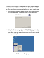
3. Click on the Setup file then the Welcome screen appears.
2
Web Browser-based Configuring
Follow the on-screen prompts to complete Http Proxy Server software installation.
A program bar appears that measures the progress of the Archttp setup. When
this screen complete, you have completed the Http Proxy Server software setup.
4. After a successful installation, the Setup Complete dialog box of the installation program is displayed. Click the close button to exit the setup wizard.
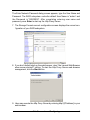
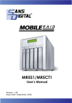
5. Click on the Start Button in the Windows 2000/XP/2003 task bar and then
click Program, select the Com2Http and run “Com2Http”. Then the Http
Proxy Server dialog box appears. If user doesn’t want to launch the web
browser, goes to step 9.
Web Browser-based Configuring
3
The Parameters for the General Setting:
(1). TCP Port value = 1 ~ 65535.
(2). RAID Connected to value = 1 ~ 10 where 1 for COM1, 2 for COM2 and so
on...
(3). BaudRate value = {2400, 4800, 9600, 19200, 38400, 57600, 115200}
NOTE: RAID subsystem controller default setting baud rate is 115200.
6. To start the Http Proxy Server web-browser management, click the Start
Button.
4
Web Browser-based Configuring
The Enter Network Password dialog screen appears, type the User Name and
Password. The RAID subsystem controller default User Name is “admin” and
the Password is “00000000”. After completing entering user name and
password, press Enter to start-up the Http Proxy Server.
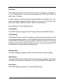
7. The Storage Console current configuration screen displays the current configuration of your RAID subsystem.
8. If you don’t default start-up the web browser, clear “the Launch Web Browser
when server started!!” setting. To start the Http Proxy Server web-browser
management, click the Start button.
9. User may execute the Http Proxy Server by entering http://[IP Address] in your
web browser.
Web Browser-based Configuring
5
1.2.2
For Linux
The following is the Linux installation procedure in the local server.
1. You may download the proxy software from Proware’s web site. The address
is “http://www.proware.com.tw/support/software.htm”.
2. Unzip HttpProxy_Linux.zip.
3. Usage: ArcHttp TCP_PORT COM_PORT BAUDRATE
Parameters: TCP_PORT value = 1 ~ 65535
COM_PORT value = 1 ~ 10 where 1 for COM1, 2 for COM2 and so on...
BAUDRATE value = {2400, 4800, 9600, 19200, 38400, 57600, 115200}
For Example:
Start the Http Proxy Server for TCP_PORT = 6666, COM_PORT = 1 and
BAUDRATE = 115200, user can type “ArcHttp 6666 1 115200” on command
line and enter to execute it.
3. Execute the Http Proxy Server by entering http://[IP Address] in the
Netscape browser provided with Linux. Note that Linux prompts you to login to
the machine with an ID of root. The RAID subsystem controller default User
Name (ID) is “admin” and the Password is “00000000”.
6
Web Browser-based Configuring
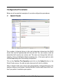
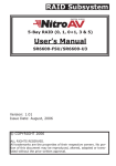
Main Menu
The main menu shows all function that enables the customer to execute actions by clicking on the appropriate link.
Individual Category
Description
Quick Create
Create a RAID configuration, which is consist of
the number of physical disk installed; it can
modify the volume set Capacity, Raid Level, and
Stripe Size.
Raid Set Functions
Create a customized raid set.
Volume Set Functions
Create customized volume sets and modify the
existed volume sets parameter.
Physical Drive
Create pass through disks and modify the existed pass through drives parameter. It also provides the function to identify the respect disk
drive.
System Control
Setting the raid system configurations
Information
View the controller and hardware monitor
information. The Raid Set Hierarchy can also
view through the RaidSet Hierarchy item.
Web Browser-based Configuring
7
Configuration Procedures
Below are a few practical examples of concrete configuration procedures.
3
Quick Create
The number of physical drives in the raid subsystem determines the RAID
levels that can be implemented with the raid set. You can create a raid set
associated with exactly one volume set. The user can change the raid level,
capacity, Volume Initialization Mode and stripe size . A hot spare option is also
created depending upon the existing configuration.
Tick on the Confirm The Operation and click on the Submit button in the
Quick Create screen, the raid set and volume set will start to initialize.
Note: In Quick Create your volume set is automatically configured based on the
number of disks in your system. Use the Raid Set Function and Volume Set Function if you prefer to customize your system.
8
Web Browser-based Configuring
4
Raid Set Functions
Use the Raid Set Function and Volume Set Function if you prefer to customize
your system. User manual configuration can full control of the raid set setting,
but it will take longer to complete than the Quick Volume/Raid Setup
configuration. Select the Raid Set Function to manually configure the raid set
for the first time or deletes existing raid set and reconfigures the raid set. A
raid set is a group of disks containing one or more volume sets.
4.1
Create Raid Set
To create a raid set, click on the Create Raid Set link. A “Select The IDE
Drive For RAID Set” screen is displayed showing the IDE drive connected to
the current controller. Click on the selected physical drives with the current
raid set. Enter 1 to 15 alphanumeric characters to define a unique identifier
for a raid set. The default raid set name will always appear as Raid Set. #.
Tick on the Confirm The Operation and click on the Submit button in the
screen, the raid set will start to initialize.
Web Browser-based Configuring
9
4.2
Delete Raid Set
To delete a raid set, click on the Delete Raid Set link. A “Select The RAID SET
To Delete” screen is displayed showing all raid set existing in the current controller.
Click the raid set number you which to delete in the select column to delete screen.
Tick on the Confirm The Operation and click on the Submit button in the
screen to delete it.
10
Web Browser-based Configuring
4.3
Expand Raid Set
Use this option to expand a raid set, when a disk is added to your system.
This function is active when at least one drive is available.
To expand a raid set, click on the Expand Raid Set link. Select the target
raid set, which you want to expand it.
Tick on the available disk and Confirm The Operation, and then click on the
Submit button in the screen to add disks to the raid set.
Web Browser-based Configuring
11
Note:
1. Once the Expand Raid Set process has started, user cannot
stop it. The process must be completed.
2. If a disk drive fails during raid set expansion and a hot spare is
available, an auto rebuild operation will occur after the raid set expansion completes.
Migrating occurs when a disk is added to a raid set. Migration status is displayed in the raid status area of the Raid Set information when a disk is added
to a raid set. Migrating status is also displayed in the associated volume status
area of the volume set Information when a disk is added to a raid set.
12
Web Browser-based Configuring
4.4
Activate Incomplete Raid Set
When one of the disk drive is removed in power off state, the raid set state will
change to Incomplete State. If user wants to continue to work, when the RAID
subsystem is power on. User can use the Activate Raid Set option to active
the raid set. After user complete the function, the Raid State will change to
Degraded Mode.
To activate the incomplete the raid set, click on the Activate Raid Set link. A
“Select The RAID SET To Activate” screen is displayed showing all raid set existing in the current controller. Click the raid set number you which to activate in
the select column.
Web Browser-based Configuring
13
Click on the Submit button in the screen to activate the raid set that has
removed one of disk drive in the power off state. The RAID subsystem will
continue to work in degraded mode.
14
Web Browser-based Configuring
4.5
Create Hot Spare
When you choose the Create Hot Spare option in the Raid Set Function, all
unused physical devices connected to the current controller appear: Select
the target disk by clicking on the appropriate check box. Tick on the Confirm
The Operation, and click on the Submit button in the screen to create the
hot spares.
The create Hot Spare option gives you the ability to define a global hot spare.
4.6
Delete Hot Spare
Select the target Hot Spare disk to delete by clicking on the appropriate check
box.
Tick on the Confirm The Operation, and click on the Submit button in the
screen to delete the hot spares.
Web Browser-based Configuring
15
4.7
Rescue Raid Set
If you try to Rescue Missing RAID Set, please contact our engineer for
assistance.
16
Web Browser-based Configuring
5
Volume Set Function
A volume set is seen by the host system as a single logical device. It is organized in a RAID level with one or more physical disks. RAID level refers to the
level of data performance and protection of a volume set. A volume set capacity can consume all or a portion of the disk capacity available in a raid set.
Multiple volume sets can exist on a group of disks in a raid set. Additional
volume sets created in a specified raid set will reside on all the physical disks
in the raid set. Thus each volume set on the raid set will have its data spread
evenly across all the disks in the raid set.
5.1
Create Volume Set
The following is the volume set features:
1.Volume sets of different RAID levels may coexist on the same raid set.
2.Up to 16 volume sets in a raid set can be created by the RAID subsystem
controller. (PATA support Master/Slave volume set, SATA supports Master volume set)
3. The maximum addressable size of a single volume set is 2 TB.
To create volume set from raid set system, move the cursor bar to the main
menu and click on the Create Volume Set link. The Select The Raid Set To
Create On It screen will show all raid set number. Tick on a raid set number
that you want to create and then click on the Submit button.
The new create volume set allows user to select the Volume name, capacity,
RAID level, strip size, Cache mode, tag queuing IDE Data Xfer Mode and IDE
channel/IDE Drive.
Web Browser-based Configuring
17
Volume Name:
The default volume name will always appear as Volume Set. #. You can rename the volume set name providing it does not exceed the 15 characters limit.
Raid Level:
Set the RAID level for the Volume Set. Highlight Raid Level and press Enter.
The available RAID levels for the current Volume Set are displayed. Select a
RAID level and press Enter to confirm.
Capacity:
The maximum volume size is default in the first setting. Enter the appropriate
volume size to fit your application.
Initialization Mode:
Set the Initialization Mode for the Volume Set. Foreground mode is faster
completion and background is instant available.
18
Web Browser-based Configuring
Strip Size:
This parameter sets the size of the stripe written to each disk in a RAID 0, 1,
0+1, or 5 logical drive. You can set the stripe size to 4 KB, 8 KB, 16 KB, 32
KB, 64 KB, or 128 KB.
A larger stripe size produces better-read performance, especially if your computer does mostly sequential reads. However, if you are sure that your computer does random reads more often, select a small stripe size
Note: RAID level 3 can’t modify strip size.
Cache Mode:
The RAID subsystem supports Write-Through Cache and Write-Back Cache.
Tag Queuing:
The Enabled option is useful for enhancing overall system performance under
multi-tasking operating systems. The Command Tag (Drive Channel) function controls the SCSI command tag queuing support for each drive channel. This function
should normally remain enabled. Disable this function only when using older SCSI
drives that do not support command tag queuing
IDE Xfer Mode
The RAID subsystem supports ATA133, ATA100, ATA66, and ATA33 Mode.
IDE Channel
Choose the IDE Channel. A Select IDE Channel dialog box appears, the Channel
I will share volume set with Channel 0, it only show Channel 0 in the dialog box.
Drive Select
The RAID subsystem supports 2 volumes (Master/Slave).
Web Browser-based Configuring
19
5.2
Delete Volume Set
To delete Volume from raid set system function, move the cursor bar to the
main menu and click on the Delete Volume Set link. The Select The Volume Set To Delete screen will show all raid set number. Tick on a raid set
number and the Confirm The Operation and then click on the Submit button to
show all volume set item in the selected raid set. Tick on a volume set number and the Confirm The Operation and then click on the Submit button to
delete the volume set.
20
Web Browser-based Configuring
5.3
Modify Volume Set
To modify a volume set from a raid set:
(1). Click on the Modify Volume Set link.
(2). Tick on the volume set from the list that you wish to modify. Click on the
Submit button.
The following screen appears.
Use this option to modify volume set configuration. To modify volume set attribute
values from raid set system function, move the cursor bar to the volume set attribute menu and click on it. The modify value screen appears. Move the cursor
bar to an attribute item, and then click on the attribute to modify the value. After
you complete the modification, tick on the Confirm The Operation and click on
the Submit button to complete the action. User can modify all values except the
capacity.
Web Browser-based Configuring
21
5.4
Volume Set Migration
Migrating occurs when a volume set is migrating from one RAID level to
another, a volume set strip size changes, or when a disk is added to a raid
set. Migration status is displayed in the volume status area of the RaidSet
Hierarchy screen when one RAID level to another, a Volume set strip size
changes or when a disk is added to a raid set.
22
Web Browser-based Configuring
5.5
Check Volume Set
To check a volume set from a raid set:
(1). Click on the Check Volume Set link.
(2). Tick on the volume set from the list that you wish to check. Tick on Confirm The Operation and click on the Submit button.
Use this option to verify the correctness pf the redundant data in a volume set.
For example, in a system with dedicated parity, volume set check means computing the parity of the data disk drives and comparing the results to the contents of the dedicated parity disk drive. The checking percentage can also be
viewed by clicking on RaidSet Hierarchy in the main menu.
5.6
Stop VolumeSet Check
Use this option to stop the Check Volume Set function.
Web Browser-based Configuring
23
6
Physical Drive
Choose this option from the Main Menu to select a physical disk and to perform the operations listed below.
6.1
Create Pass-Through Disk
To create pass-through disk, move the mouse cursor to the main menu and
click on the Create Pass-Through link. The relative setting function screen
appears.
Disk is no controlled by the RAID subsystem firmware and thus cannot be a
part of a volume set. The disk is available to the operating system as an
individual disk. It is typically used on a system where the operating system is
on a disk not controlled by the RAID firmware. User can also select the cache
mode, Tagged Command Queuing, IDE Data Xfer Mode and IDE channel/IDE
Drive for this volume.
24
Web Browser-based Configuring
6.2
Modify Pass-Through Disk
Use this option to modify the Pass-Through Disk Attribute. User can modify the
cache mode, Tagged Command Queuing, IDE Data Xfer Mode and IDE channel/IDE Drive on an existed pass through disk.
To modify the pass-through drive attribute from the pass-through drive pool,
move the mouse cursor bar to click on Modify Pass-Through link. The Select
The Pass Through Disk For Modification screen appears tick on the PassThrough Disk from the pass-through drive pool and click on the Submit button
to select drive.
The Enter Pass-Through Disk Attribute screen appears, modify the drive attribute values, as you want.
Web Browser-based Configuring
25
6.3
Delete Pass-Through Disk
To delete pass-through drive from the pass-through drive pool, move the
mouse cursor bar to the main menus and click on Delete Pass Through link.
After you complete the selection, tick on the Confirm The Operation and click
on the Submit button to complete the delete action.
6.4
Identify Selected Drive
To prevent removing the wrong drive, the selected disk LED will light for physically locating the selected disk when the Identify Selected Drive is selected.
To identify the selected drive from the drives pool, move the mouse cursor bar to
click on Identify Selected Drive link. The Select The IDE Device For identification screen appears tick on the IDE device from the drives pool and Flash method.
After completing the selection, click on the Submit button to identify selected
drive.
26
Web Browser-based Configuring
7
7.1
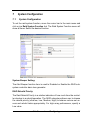
System Configuration
System Configuration
To set the raid system function, move the cursor bar to the main menu and
click on he Raid System Function link. The Raid System Function menu will
show all items. Select the desired function.
System Beeper Setting:
The Alert Beeper function item is used to Disabled or Enable the RAID subsystem controller alarm tone generator.
RAID Rebuild Priority:
The Raid Rebuild Priority is a relative indication of how much time the controller devotes to a rebuild operation. The RAID subsystem allows user to choose
the rebuild priority (ultraLow, Low, Medium, High) to balance volume set access and rebuild tasks appropriately. For high array performance, specify a
Low value.
Web Browser-based Configuring
27
Terminal Port Configuration:
Speed setting values are 1200, 2400, 4800, 9600, 19200,38400, 57600, and
115200.
Stop Bits values are 1 bit and 2 bits.
Note: Parity value is fixed at None.
Data Bits value is fixed at 8 bits.
JBOD/RAID Configuration
The RAID subsystem supports JBOD and RAID configuration.
Maximum ATA Mode Supported:
Within the subsystem, the host IDE channels act as a target and 4 Ultra ATA
bus are connected to the drive. The 4 Ultra ATA drive channel can support up
to ATA133, which runs up to 133MB/s.
28
Web Browser-based Configuring
7.2
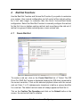
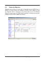
View Events
To view the RAID subsystem controller’s information, move the mouse cursor
to the main menu and click on the System Information link. The Raid Subsystem events Information screen appears.
Choose this option to view the system events information: Timer, Device,
Event type, Elapse Time and Errors. The RAID system does not built the real
time clock. The Time information is the relative time from the RAID subsystem
power on.
Web Browser-based Configuring
29
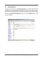
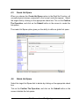
7.3
Generate Test Events
If you want to generate test events, move the cursor bar to the main menu and
click on he Generate Test Events. Tick on the Confirm The Operation, and
click on the Submit button in the screen to create the hot spares. Then click
on the View Events/Mute Beeper to view the test event.
30
Web Browser-based Configuring
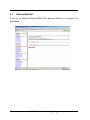
7.4
Clear Events Buffer
Use this feature to clear the entire events buffer information.
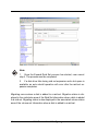
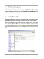
7.5
Modify Password
To set or change the RAID subsystem password, move the mouse cursor to Raid
System Function screen, and click on the Change Password link. The Modify
System Password screen appears.
Web Browser-based Configuring
31
The password option allows user to set or clear the raid subsystem’s password protection feature. Once the password has been set, the user can only
monitor and configure the raid subsystem by providing the correct password.
The password is used to protect the internal RAID subsystem from unauthorized entry. The controller will check the password only when entering the
Main menu from the initial screen. The RAID subsystem will automatically go
back to the initial screen when it does not receive any command in ten
seconds.
To disable the password, press Enter key only in both the Enter New Password
and Re-Enter New Password column. Once the user confirms the operation
and clicks the Submit button. The existing password will be cleared. No password checking will occur when entering the main menu from the starting screen.
7.6
Upgrade Firmware
Please reference the chapter 4 for more information.
32
Web Browser-based Configuring
8
8.1
Information Menu
RaidSet Hierarchy
Use this feature to view the internal raid subsystem current raid set, current volume set and physical disk configuration.
8.2
System Information
To view the RAID subsystem controller’s information, move the mouse cursor to
the main menu and click on the System Information link. The Raid Subsystem
Information screen appears.
Use this feature to view the raid subsystem controller’s information. The controller name, firmware version, serial number, main processor, CPU data/Instruction cache size and system memory size/speed appear in this screen.
Web Browser-based Configuring
33
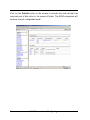
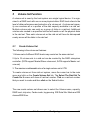
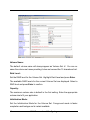
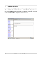
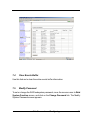
8.3
Hardware Monitor
To view the RAID subsystem controller’s hardware monitor information, move the
mouse cursor to the main menu and click the Hardware Monitor link. The Hardware Information screen appears.
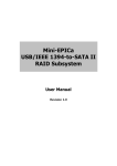
The Hardware Monitor Information provides the temperature, fan speed (chassis
fan) and voltage of the RAID subsystem. All items are also unchangeable. The
warning messages will indicate through the LCD, LED and alarm buzzer.
Item
Warning Condition
Controller Board Temperature
> 60 Celsius
Backplane Temperature
> 55 Celsius
Controller Fan Speed
< 2600 RPM
Power Supply +12V
< 10.8V or > 13.2V
Power Supply +5V
< 4.5V or > 5.5V
Power Supply +3.3V
< 2.97V or > 3.63V
CPU Core Voltage +1.5V
< 1.35V or > 1.65V
34
Web Browser-based Configuring
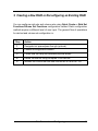
9 Creating a New RAID or Reconfiguring an Existing RAID
You can configure raid sets and volume sets using Quick Create or Raid Set
Functions/Volume Set Functions configuration method. Each configuration
method requires a different level of user input. The general flow of operations
for raid set and volume set configuration is:
Step
Action
1
Designate hot spares/pass-through (optional).
2
Choose a configuration method.
3
Create raid set using the available physical drives.
4
Define volume set using the space in the raid set.
5
Initialize the volume set and use volume set in the HOST OS.
Web Browser-based Configuring
35
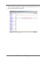
10 Upgrading Firmware
Get the new version firmware for your RAID subsystem controller.
1. To upgrade the RAID subsystem firmware, move the cursor to Upgrade
Firmware link. The Upgrade The Raid System Firmware screen
appears.
2. Click Browse. Look in the location where the Firmware upgrade software is
located. Select the File name:
“6160FIRM.BIN” and click open.
3. Click the Confirm The Operation and press the Submit button.
4. The Web Browser begins to download the firmware binary to the controller
and start to update the flash ROM.
36
Web Browser-based Configuring
5. After the firmware upgrade is complete, a bar indicator will show “ Firmware Has Been Updated Successfully”
Web Browser-based Configuring
37