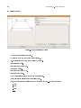
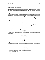
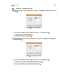
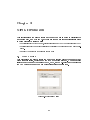
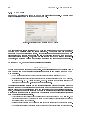
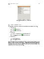
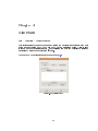
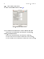
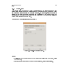
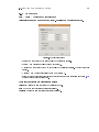
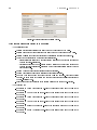
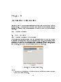
1
DEMPACK User Manual Version 1.0 International Center for Numerical Methods in Engineering CIMNE April 2011 1 2 Contents 1 Introduction 1.1 DEMPack Wizards . . . . . . . . . . . . . . . . . . . . . . . . . . . . . . . . . . . . 1.2 DEMPack Toolbar . . . . . . . . . . . . . . . . . . . . . . . . . . . . . . . . . . . . 1.3 GiD's Menu bar . . . . . . . . . . . . . . . . . . . . . . . . . . . . . . . . . . . . . . 5 6 7 8 2 Global Data 2.1 Global . . . . . . . . . . . . . . . . . . . . . 2.1.1 Heading Data . . . . . . . . . . . . . 2.1.2 Control Time . . . . . . . . . . . . . 2.1.2.1 Calculation of time step . . 2.2 Output . . . . . . . . . . . . . . . . . . . . 2.2.1 Result Outputs . . . . . . . . . . . . 2.2.1.1 Nodal Results . . . . . . . 2.2.1.2 FEM Results . . . . . . . . 2.2.1.3 DEM Results . . . . . . . . 2.2.2 History Outputs . . . . . . . . . . . 2.2.2.1 FEM History . . . . . . . . 2.2.2.2 DEM History . . . . . . . . 2.2.2.3 History: Variable to Follow 2.3 Curves . . . . . . . . . . . . . . . . . . . . . 2.4 Damping . . . . . . . . . . . . . . . . . . . 2.4.1 Damping Theory . . . . . . . . . . . 2.4.1.1 Viscous Damping . . . . . 2.4.1.2 Non-Viscous Damping . . . 2.4.2 Damping Parameters Setup . . . . . . . . . . . . . . . . . . . . . . . . . . . . . . . . . . . . . . . . . . . . . . . . . . . . . . . . . . . . . . . . . . . . . . . . . . . . . . . . . . . . . . . . . . . . . . . . . . . . . . . . . . . . . . . . . . . . . . . . . . . . . . . . . . . . . . . . . . . . . . . . . . . . . . . . . . . . . . . . . . . . . . . . . . . . . . . . . . . . . . . . . . . . . . . . . . . . . . . . . . . . . . . . . . . . . . . . . . . . . . . . . . . . . . . . . . . . . . . . . . . . . . . . . . . . . . . . . . . . . . . . . . . . . . . . . . . . . . . . . . . . . . . . . . . . . . . . . . . . . . . . . . . . . . . . . . . . . . . . . . . . . . . . . . . . . . . . . . . . . . . . . . . . . . . . . . . . . . . . . . . . . . . . . . . . . . . . . . . . . . . . . . . . . . . . . . . . . . . . . . . . . . . . . . . . . . . . . . . . . . . 9 9 9 11 11 12 12 12 13 14 15 15 16 17 18 21 21 21 21 23 3 Mesh Denition 3.1 Mesh Setting . . . . . . . . . 3.1.1 DEM Mesh . . . . . . 3.1.2 DEM Rigid Mesh . . . 3.1.3 FEM mesh . . . . . . 3.2 Meshing Preferences . . . . . 3.2.1 DEM Mesher Options 3.3 Mesh Element Type . . . . . . . . . . . . . . . . . . . . . . . . . . . . . . . . . . . . . . . . . . . . . . . . . . . . . . . . . . . . . . . . . . . . . . . . . . . . . . . . . . . . . . . . . . . . . . . . . . . . . . . . . . . . . . . . . . . . . . . . . . . . . . . . . . . . . . . . . . . . . . . . . . . . . . . . . . . . . . . . . . . . . . 25 25 26 27 27 28 28 29 4 Materials 4.1 DEM Material . . . . . . . . . . . . . . . . 4.1.1 Linear Elastic model . . . . . . . . . 4.1.2 Linear Elastic Brittle model . . . . 4.1.3 Linear Elastic Brittle Rolling model 4.1.4 Linear Elastic Plastic model . . . . 4.1.5 Linear Elastic Softening model . . . 4.1.6 NonLinear Hertz-Mindlin model . . 4.2 FEM Material . . . . . . . . . . . . . . . . . 4.3 DEM-Rigid Material . . . . . . . . . . . . . . . . . . . . . . . . . . . . . . . . . . . . . . . . . . . . . . . . . . . . . . . . . . . . . . . . . . . . . . . . . . . . . . . . . . . . . . . . . . . . . . . . . . . . . . . . . . . . . . . . . . . . . . . . . . . . . . . . . . . . . . . . . . . . . . . . . . . . . . . . . . . . . . . . . . . . . . . . . . . . . . . . . . . . . . . . . . . . . . . . . . . . . . . . . . . . . . . . . . . 31 32 33 34 35 36 37 38 39 40 . . . . . . . . . . . . . . . . . . . . . . . . . . . . . . . . . . . . . . . . . . 3 . . . . . . . 4 5 Kinematics Condition 5.1 Kinematics . . . . . . . . 5.1.1 Constrains . . . . 5.1.2 Initial Conditions . 5.1.3 Movements . . . . 5.1.4 Master-Slave . . . 5.2 Concentrated Mass . . . . CONTENTS . . . . . . 41 41 42 43 44 45 46 6 Loads 6.1 Gravity and External Loads . . . . . . . . . . . . . . . . . . . . . . . . . . . . . . . 6.1.1 Gravity . . . . . . . . . . . . . . . . . . . . . . . . . . . . . . . . . . . . . . 6.1.2 Nodal Loads . . . . . . . . . . . . . . . . . . . . . . . . . . . . . . . . . . . 47 47 47 49 7 Contacts 51 8 Advanced Conditions 8.1 DEM Cohesion . . . . . . . . . . . . . . . . . . . . . . . . . . . . . . . . . . . . . . 53 53 A Windows Installation Guide 55 B Linux Installation Guide 57 . . . . . . . . . . . . . . . . . . . . . . . . . . . . . . . . . . . . . . . . . . . . . . . . . . . . . . . . . . . . . . . . . . . . . . . . . . . . . . . . . . . . . . . . . . . . . . . . . . . . . . . . . . . . . . . . . . . . . . . . . . . . . . . . . . . . . . . . . . . . . . . . . . . . . . . . . . . . . . . . . . . . . . . . . . . . . . . . . . . . . . . . . . Chapter 1 Introduction This is a user manual for the software DEMPack v1.0b, a guide for the medium user familiar with this software and with experience in the world of Discrete Element Method analysis. The manual is divided into eight chapters each of them contains the necessary data to dene a typical model: • Global Data • Mesh Denition • Material • Kinematics • Loads • Contacts • Advanced Conditions The order of the chapters is somewhat orientative of the order that the user will follow to dene a model. Nevertheless, the creation sequence will depend on the way choosen by the user to create the project and the nature of the problem under analysis. Each chapter of this manueal includes an explanation of all the windows and buttons DEMPack v1.0b interfase, and a brief guide of how to use them correctly. The common structure of each chapeter is to shown rst the main window that the user will nd when denind the project condition, followed by the denietion of each parameter neede in that particular case. Additionally, there will be after each section and subsection tittle the menu route to acces to the particular section using the menu bar in GiD's window top. For example, the menu route to create a point using the menu bar would be: Geometry > Create > Point All the problem data can be accesed by three diferent ways, each of them are equivalent and can be used without distinction. • DEMPack Wizards • DEMPack Toolbar • GiD Menu Bar Those three diferent methods are implemented in the interface of DEMPack v1.0b in order to easy the use of the program and increase the exibity when creating diferent models. 5 6 CHAPTER 1. 1.1 INTRODUCTION DEMPack Wizards When running DEMPack v1.0b, a plash window shows the user the Wizard Choice Window. Figure 1.1: Wizards Menu splash window This version of DEMPack includes several wizards in order to guide a novel user to model dierent kind of problems according of its nature: • Storage Silo • Industrial Mill • Rock Cutting, by disc or by pick Those wizards will guide the user in a straight way in order to create correctly the desired model. The Advanced User option does not load any wizard, but the Advanced User Toolbar (see 1.2) . In any moment, the user can load this toolbar and modify and work with the current model. The wizard type is xed once it's choosen from the Wizard Choice Window, and the user should re-load the problem type in order to change the type wizard (with the toolbar exception). The splash window shows also the forthcomming wizards that CIMNE is now developing in order to add them into DEMPack in a next future. 1.2. 1.2 DEMPACK TOOLBAR 7 DEMPack Toolbar The DEMPack Advanced User Toolbar is a very useful tool that allows the user to work in a exible way in any desired model. The user can acces to any step of the denition sequence of a model anytime and control every parameter, by loading it from the beginning by the choice of Advanced User option in the splash window, or by the GiD's menu bar in DEMPack > Load Advanced User Toolbar. Figure 1.2: DEMPact Toolbar expanded view The grade of exibiliy to work with the toolbar is the main reason why only experienced users of DEMPack should work with it, since a wrong assignation methodology will make the model to be incomplete or incorrect, and the program will not work properly. 8 CHAPTER 1. 1.3 INTRODUCTION GiD's Menu bar The program in wich DEMPack is based, GiD, shows a typical menu bar at the top screen that includes the typical working parameters of a pre-post processing program. DEMPack creates its on menu, including some useful commands: • DEMPack Wizard's Menu: shows the Wizard's Menu splash window, or the choosen Wizard, if any. • Load Advanced User Toolbar: shows the toolbar in any moment. • User Manual: shows the the whole DEMPAck User Manual. Besides this, there is also the option of accessing to all the denition elds used in DEMPack, in case of necesary, apperaring under the Data menu. For more information about thisMenu bar, check GiD's Reference in Help menu. Chapter 2 Global Data Data > Global Data The Global Data menus allows setting global parameters that govern the whole problem such as the simulation time, outputs for postprocessing, time curves denitions and global damping parameters. The user can also access to those menu y clicking the GIF icon on the Advanced User toolbar. 2.1 Global Data > Global Data > Global Allows setting global parameters: simulation time, degrees of freedom and time step. 2.1.1 Heading Data Data > Global Data > Global > Heading Data Figure 2.1: Heading Data Problem Dimension: species if the problem is in 2 or 3 dimensions. Degree of Freedom: species the degrees of freedom of each node. • 2D: the user can allow only displacement in two degrees of freedom ( X and Y axis) or in three degrees of freedom, that involves displacement plus rotation of the node. 9 10 CHAPTER 2. GLOBAL DATA • 3D: the user can allow only displacement in three degrees of freedom ( X, Y and Z axis) or in six degrees of freedom, that involves displacement plus rotation of the node. This gadget allows the user to add notes related with the model. It is useful when working with large models where many information is dened or when working with a set of models where just one parameter (ie: the material density or the time step) diers from each other. Add Comment: Figure 2.2: Add comment window 2.1. 11 GLOBAL 2.1.2 Control Time Data > Global Data > Global > Control/Time Figure 2.3: Control/Time • End Time: is the nal time of the simulation. The simulation runs from time = 0 to time = end_time • Time Step Type: Automatic: the time step is calculated automatically based in the minimun critical step factor and scaled by the time step factor. Dened: allows to specify the exact time step wanted to be used. The value is dened in Time Step. • Time Step Factor: The Time Step Factor is a value between 0.0 and 1.0. 2.1.2.1 Calculation of time step The automatic time step is calculated as the time step factor times the minimum element size (i.e. radius of the smallest particle) divided by the maximum norm of the velocity at that moment. 12 CHAPTER 2. 2.2 GLOBAL DATA Output Data > Global Data > Output 2.2.1 Result Outputs • Results Type: the results for postprocessing can be saved based on the number of time steps or a prescribed time interval. Steps: denes the number of results to write the output le. Delta Time: denes the time interval to write the output le. 2.2.1.1 Nodal Results Saves physical quantities measured at each node in the system. Figure 2.4: Outputs: Nodal • Displacement: saves the displacement of each node. • Angular Displacement: saves the rotation of each node. • Velocity: saves the translational velocity of each node. • Angular Velocity: saves the angular velocity of each node in case of rotation activated. • Acceleration: saves the linear acceleration of each node. • Temperature: saves the temperature of each node. 2.2. 13 OUTPUT • Pressure: saves the pressure value of each node. • Contact Pressure: saves the pressure generated by the contact between two meshes. • Forces: saves the forces acting on each node. • Stress: saves the nodal stress. FEM nodes: the stress is projected from Gauss points to nodes. DEM nodes: the stress is based in micromechanics. • Principal Stress: saves the principal stresses based in nodal stress. 2.2.1.2 FEM Results Saves physical quantities of FEM elements, based in Gauss points. Figure 2.5: Outputs: FEM • Log Strain: saves the logarithmic strain of the element. • EQP Strain: saves the equivalent plastic strain of the element. • Von Mises: Saves the equivalent Von Mises Stress of the element. 14 CHAPTER 2. GLOBAL DATA 2.2.1.3 DEM Results Saves physical quantities of DEM elemens. Figure 2.6: Outputs: DEM • Wear: wear of each DEM element. Only present for DEM-RIGID problems. • Radius: radius of DEM element (circles or spheres). • Density: density of the DEM zone: takes into account nearby voids. It is based in the average procedure around each element. • Broken Bond: shows if the element has at least one bond broken. Only valid when cohesion between elements exists. • Damage: local variable of damage, based on: D =1− current bonds initial bonds • Contacts: shows potential and bonded contacts between elements. • Void Ratio: shows an estimation of void space around each element 2.2. 15 OUTPUT 2.2.2 History Outputs • History Type: the historic results to graph can be saved based on the number of time steps or a prescribed time interval. Steps: denes the number of results to write the output le. Delta Time: denes the time interval to write the output le. 2.2.2.1 FEM History Creates output graphs of physical quantities of FEM elements, based in Gauss points. Figure 2.7: History: FEM window • Energy: Plots the total kinetic energy of the system 16 CHAPTER 2. 2.2.2.2 DEM History Creates output graphs of physical quantities of DEM elements. Figure 2.8: History: DEM window • Cohesion: Plots the cohesion value for each element • Contacts: Plots the contact value for each element. • Stress: Plots the stress value for each element. • Energy: Plots the total kinetic energy of each element. GLOBAL DATA 2.2. 17 OUTPUT 2.2.2.3 History: Variable to Follow This section allows the user to obtain detailed results graphs in the nodes of special interest of the project. Figure 2.9: Variables to Follow Variable to follow: selected node. denes the nodal variable that will be graphed in the • Displacement: the graph will show the evolution of the nodal displacement in the dened degrees of freedom. • Velocity: the graph will show the evolution of the nodal velocity in the dened degrees of freedom. • Acceleration: the graph will show the evolution of the nodal acceleration in the dened degrees of freedom. • Load: the graph will show the evolution of the nodal load in the dened degrees of freedom. Those variables can be assigned to a node using: Assign Assigns the historic condition to the selected node. Draw Shows the historic conditions previously assigned. Unassign Erases the historic conditions previously assigned. 18 CHAPTER 2. 2.3 Curves Data > Global Data > Output This section allows the user to dene auxiliar curves. Figure 2.10: Curves Denition: Main • New: Creates a new curve of Type: Lineal, Sinoidal or By points • Edit: allows to edit the parameters of a previously dened curve. • Delete: deletes the selected curve. Lineal Curve: Figure 2.11: Curve Denition: Lineal • Name: Name identifying the curve. • Type: shows the type of the curve being created. GLOBAL DATA 2.3. 19 CURVES • t0: starting time of the line. • f0: value of the curve at t0. • tf: endting time of the line. • : value of the curve at tf. • Create Curve: creates the curve with the specied parameters. • Cancel: leaves the creation/editing of the curve. Sinoidal Curve: Figure 2.12: Curve Denition:Sinoidal • Name: Name identifying the curve. • Type: shows the type of the curve being created. • A: amplitude. • b: oset value in the ordinate axis. • w: angular frequency of oscillation. • t0: initial time. • tf: nal time. • Create Curve: creates the curve with the specied parameters. • Cancel: leaves the creation/editing of the curve. 20 CHAPTER 2. GLOBAL DATA By Points Curve: Figure 2.13: Curve Denition: By points • Name: Name identifying the curve. • Type: shows the type of the curve being created. • N. of Points: shows the number of points of the curve. • t0: initial time point. • f0: value of the curve at t0. • t1: rst time point. • f1: value of the curve at t1. • t2: second time point. • Load Curve: allows to load a curve from a external le. • Clear All Points: deletes all the points introduced. • Give Format: converts the inline form of the data: t0 f0 t1 f1 ... to a formated form: t0 f0 t1 f1 t2 f2 ... 2.4. 21 DAMPING 2.4 Damping Data > Global Data > Damping In this section the user can dene the type of Emery dissipation that will act in the the system modeled through the denition of damping. See next Damping Theory section for more details. 2.4.1 Damping Theory The energy given to the system (spheres) is dissipated through the frictional sliding. However the frictional sliding can be deactivated in a model, or being activated, it can not be enough to become a stable solution in a reasonable number of cycles. The non-viscous local damping available in the software dispels eciently the damping energy through the movement equations. The non-viscous local damping is controlled dening a constant damping for each particle or sphere. 2.4.1.1 Viscous Damping The damping is proportional to the applied velocity: Fid = −Ci · vi Equation is valid when amplitude and frequency are used. In this case, the Fid is the nodal damping force, vi the nodal velocity and Ci is the damping coecient. Ci = 2 · β · Mi Where Mi is the concentrated mass and β is the damping coecient obtained as the sum of the SET i nodes damping coecients. β= X βi n Being n the damping number of the SET. The umpteenth SET damping coecient is calculated by the formula: βn = 100 1 · ln( ) tr fp Where fp is the percentage of the damped vibration amplitude (A) regarding to free vibration amplitude (A0 ) after a certain time tr : fp = A ·100 A0 2.4.1.2 Non-Viscous Damping The non-viscous local damping is similar to the developed in reference [X]. A damping force term can be included in the movement (translation and rotation) equations formulation given by the expressions: Fi = m · (ẍ − gi ) Mi = I · ω˙3 = (ψ · m · R2 )·ω Where the ϕ value varies in function of the distinct element type: • ϕ = 0,4 for spheres (3D) • ϕ = 0,5 for circles (2D) 22 CHAPTER 2. GLOBAL DATA Then, the previous equations can be written as: Fi + Fid = Mi · Ai ( M i · Ai = mi · ẍi I · ω3 f or i = 1, 2 f or i = 3 Where Fi , Mi and Ai are the generalized force, the mass and the component of acceleration, respectively. The term Fi includes the gravity and Fid includes the damping force. The damping force in the non-viscous case is: Fi = −αi |Fi | · sign(Vi ) sign(y) f or i = 1, ..., 3 +1 if y > 0 = −1 if y < 0 0 if y < 0 With the velocity expressed in the general terms: ( Vi = ẍi ω f or i = 1, 2 f or i = 3 By that, in non-viscous case the damping force is controlled by the constant α and the damping torque is controlled by the constant β 2.4. 23 DAMPING 2.4.2 Damping Parameters Setup Viscous Damping: velocity. the energy dissipated in the system of particles is proportional to the nodal Figure 2.14: Damping: Viscous • Damping mode: allows to choose Viscous Damping or Non Viscous Damping. • Amplitude: global damping amplitude. • Frequency: global damping frequency. Non-Viscous Damping: the nodal forces. the energy dissipated in the system of particles is proportional to Figure 2.15: Damping: Non Viscous • Damping mode: allows to choose Viscous Damping or Non Viscous Damping. • Alpha: damping constant for translational degrees of freedom. • Beta: damping constant for rotational degrees of freedom. 24 CHAPTER 2. GLOBAL DATA Chapter 3 Mesh Denition This section allows the user to create and dene the mesh in order to discretize the model geometry. In DEMPack v1.0b there are three main steps necessaries in order to dene correctly a desired mesh: • Properties: Sets the type of mesh, discrete elements mesh (DEM) or nite elements (FEM) • Preferences: Sets the meshing preferences to establish the parameters of the mesher algo- rithm. • Element Type: Sets the type element of each mesh 3.1 Mesh Setting This part allows the user to create the mesh for a specic part of the geometry and dene it's properties, depending of the type of problem studied. The user should select at rst the mesh type desired (DEM, FEM, and DEM-Rigid) and then click on the New button to dene the mesh properties specic for each type. Figure 3.1: Mesh Setting Window 25 26 CHAPTER 3. 3.1.1 MESH DEFINITION DEM Mesh In gure 3.2 appears the window of DEM mesh denition properties. The user must select an available layer in order to dene the mesh. Figure 3.2: Properties window denition for DEM meshes The global contact search tolerance (CTOL) is the distance used to compute contacts between DEM particles using the search algorithm. This parameter has a high inuence in the computational eciency. If this value is too small there are too much global search and contact elements in the list. If this value is too big, then the potential contact list is too long. This, bring out the contact check to be big and inecient. Therefore, an optimum value must be found as a fragment of sphere medium radius. To choose CTOL, DEMPack uses the following criteria: CT OL ∈ (0.1r, 0.5r) Where r is the mean radius of the spheres. If spheres sizes are very variable (some very big and some very small) this criteria probably is not enough and the CTOL may be scaled. • CTOL Factor: Scale factor to reduce the global contact search tolerance (CTOL) • Rotational Inertia Scaled factor: Sacale factor for rotational inertia of each DEM element, in a range of 0.0 to ∞. Values between 0.0 and 1.0 decrease the rotational inertia of the elements and greater than 1.0 increase the rotational inertia. This allows increasing a little bit the rotational inertia without changing a lot the global movement (the rotational movement seems not to be so important because the kinetic energy in the translation movement is greater than the rotational kinetic energy). This allows to use the critic time dened in the lineal vibrations (for translation movements) formula which is higher than the critic time for the rotational vibrations with the actual rotational inertia. • Void Tolerance: Used tolerace for the estimation of void space around a DEM element. The void space is the ratio by divinding the volume of the tolerance value increased radius and the origina volume of the element. • Delete: Special condition that deletes the elements when all its bonded contacts are broken. • No Penetration: Scales the radius in order to ensure that not exists overlap between elements. 3.1. 27 MESH SETTING 3.1.2 DEM Rigid Mesh The user can dene a DEM mesh with those special elements for the analysis of wear with change of shape. The denition of this mesh is the same that for the standard DEM meshes, plus the denition of a slave mesh which the DEM-rigid elements will interact. Figure 3.3: Properties window denition for DEM-Rigid meshes 3.1.3 FEM mesh In gure 3.4 appears the window of FEM mesh denition properties. The user must select an available layer in order to dene the mesh. Figure 3.4: Mesh: FEM 28 3.2 CHAPTER 3. MESH DEFINITION Meshing Preferences This part allows the user to establish the parameters of DEMPack mesher in order to get an accurate mesh to the geometry under study. Once in the appropriate window, see gure 3.5, the user can access to the DEM Mesher Options window, generate the mesh and then check the quality of it, by using the appropriate buttons. More information of meshing can be found in GiD Help. Figure 3.5: Meshing preferences main window 3.2.1 DEM Mesher Options In gure 3.6 and 3.7 appear both pages that complete the needed parameters for the DEM Mesher. The user can nd an extensive explanation of these parameters in GiD help menu at Help>Preferences>Meshing. Figure 3.6: Main options of DEM mesher window 3.3. 29 MESH ELEMENT TYPE Figure 3.7: Filter options of DEM mesher window 3.3 Mesh Element Type In this section the user can dene the type of element that will form the mesh. • Discrete elements 2D case: circle element 3D case: sphere elements • Finite elemens 2D case: triangular and quadrilateral elements 3D case: tetrahedral and hexahedral elements • Rigid elements 2D case: 3D case: lineal element surface element It very important to keep the coherence between the mesh type and the element type (ie: a DEM Mesh only can be composed by discrete elements) and also between the element type and the problem dimension. This last aspect is automatically forced when using any of the DEMPack Wizards but it is open to the user decision when working with the Advanced User Toolbar. 30 CHAPTER 3. MESH DEFINITION Chapter 4 Materials Data > Materials > Assign Material This section allows the user to dene and assign the material properties to each part of the model by using DEM , FEM and DEM-RIGID material models. A list of used is shown in the Materials Window, and the user can edit and delete the assigned materials by using the appropriate buttons. The window model denition is shown in Figure 4.1: Figure 4.1: Materials window 31 32 4.1 CHAPTER 4. MATERIALS DEM Material The available DEM material models are listed below following the degree of complexity of the model: Linear Elastic Elastic Brittle Brittle Rolling Elastic Plastic Elastic Softening Non-Linear Hertz-Mindlin In many cases, each step adds some parameters to the material model previously dened. This usually happens when the user activates certain option that will be noted in the following model explanation, from the simplest to the most complex one. 4.1. 33 DEM MATERIAL 4.1.1 Linear Elastic model The window model denition is shown in Figure 4.2: Figure 4.2: Linear Elastic model window With: • Density: Density of the material. • Stiness normal: Elastic stiness in normal direction for a compression state. • Stiness tangential: Tangential elastic stiness. • Coulomb Friction: Coulomb friction coecient. • Damping Normal Factor: Damping coecient between spheres. This is part of the system critical damping. 34 CHAPTER 4. 4.1.2 MATERIALS Linear Elastic Brittle model The window model denition is shown in Figure 4.3: Figure 4.3: Linear Elastic Brittle model window With the addition to the previous dened model of the following parameters: • Stiness Normal Com: Elastic stiness in normal direction for a compressive state. Optional If cohesion is dened: • Stiness Normal Tens: Elastic stiness in normal direction for a tensile state. • Max Force Normal: Maximum normal eort to consider contact between two spheres. • Max Force Tangential: Maximum tangential eort to consider contact between two spheres. 4.1. DEM MATERIAL 4.1.3 Linear Elastic Brittle Rolling model The window model denition is shown in Figure 4.4: Figure 4.4: Linear Elastic Brittle Rolling model window Optional If Rolling is dened: • Rolling Friction: is the friction coecient of the elements to roll. • Rolling Stiness: elastic stiness for a torsional load state. 35 36 CHAPTER 4. 4.1.4 MATERIALS Linear Elastic Plastic model The window model denition is shown in Figure 4.5: Figure 4.5: Linear Elastic Plastic model window With the addition to the previous dened model of the following parameters: • Residual Friction: Residual friction factor acting in the plastic deformation. • Max Plastic Displacement: Maximum plastic displacement. 4.1. 37 DEM MATERIAL 4.1.5 Linear Elastic Softening model The window model denition is shown in Figure 4.6: Figure 4.6: Linear Elastic Softening model window With the addition to the previous dened model of the following parameters: • Softening modulus: computational mechanic's classic parameter of softening modulus. 38 CHAPTER 4. 4.1.6 MATERIALS NonLinear Hertz-Mindlin model The window model denition is shown in Figure 4.7: Figure 4.7: NonLinear Hertz-Mindlin model window This material model uses a dierent formulation to dene the material properties, then it uses other parameters, listed below: • Density: Density: Density of the material. • Young Modulus: Young Modulus value. • Poisson Ratio: Poisson ratio. • Coulomb Friction: Coulomb friction coecient. • Damping Normal Factor: Damping coecient between spheres. . 4.2. 39 FEM MATERIAL 4.2 FEM Material There is only one type of FEM materials. This material is called Elasto-Plastic and the window is shown in Figure 4.8: Figure 4.8: Elasto-Plastic material window With: • Young Modulus: Young modulus value. • Poisson Coecient: Poisson coecient value. • Density: Density of the material. • Uniaxial Strength: Initial yield stress. • Hardening: Linear isotropic hardening parameter. 40 CHAPTER 4. 4.3 MATERIALS DEM-Rigid Material There is only one type of DEM-Rigid material. This material is called Linear ElasticWear and the window is shown in Figure 4.9: Figure 4.9: Linear Elastic Wear material Window With: • Density: Density of the material. • Coulomb friction: Coulomb Friction coecient. • Stiness Normal: Elastic stiness in normal direction. • Damping Normal Factor: Damping coecient between spheres. This is a part of critical damping. • Wear Constant: controls the wear of the material due to forces acting on it. • Hardness: surface hardness of the material. • Temperature Curve: denes the variation with time of the hardness. Chapter 5 Kinematics Condition Data > Kinematics In this section the user can dene the kinematics conditions of the model. This includes the movement, the boundary constrains the mass or inertial properties of the dierent parts of the model. 5.1 Kinematics Data > Kinematics > Kinematics Figure 5.1: Working triad for assign, visualize and erase conditions In the discrete elements models dened by spheres the kinematics conditions more used are the initial displacement and prescribed velocities. All the conditions shown separately in this paragraph can be used together and can be assigned using: Assign to Assigns the kinematic condition to the selected entities. Draw Shows the kinematic conditions previously assigned. Unassign Erases the kinematic conditions previously assigned. 41 42 CHAPTER 5. 5.1.1 KINEMATICS CONDITION Constrains This sections allows the user to restrain nodes, either DEM or FEM, in the desired degrees of freedom. The window model denition is shown in Figure 5.2: Figure 5.2: Constrains denition window With • Dene constrains: X constrain: Restriction applied in X axis. Y constrain: Restriction applied in Y axis. Z constrain: Restriction applied in Z axis (only available in 3D models) Ang. X contrain: Rotation restriction applied in X axis (only available in 3D models). Ang. Y contrain: Rotation restriction applied in Y axis (only available in 3D models). Ang. Z contrain: Rotation restriction applied in Z axis. 5.1. 43 KINEMATICS 5.1.2 Initial Conditions This sections allows the user to dene the initial displacements or velocities in the desired degrees of freedom and assign it to points or nodes, either DEM or FEM. The window model denition is shown below: Figure 5.3: Initial conditions denition window, 2D mode With: • Dene Initial velocity conditions: Linear X: Lineal velocity in X axis Linear Y: Lineal velocity in Y axis Linear Z: Lineal velocity in Z axis (only available in 3D models). Angular X: Rotation velocity in X axis (only available in 3D models). Angular Y: Rotation velocity in Y axis (only available in 3D models). Angular Z: Rotation velocity in Z axis • Dene Initial displacements conditions: Linear X: Lineal displacement in X axis Linear Y: Lineal displacement in Y axis Linear Z: Lineal displacement in Z axis (only available in 3D models). Angular X: Rotation displacement in X axis (only available in 3D models). Angular Y: Rotation displacement in Y axis (only available in 3D models). Angular Z: Rotation displacement in Z axis 44 CHAPTER 5. 5.1.3 KINEMATICS CONDITION Movements This section allows the user to dene a prescribed velocity and assign it to nodes, either DEM or FEM. In 2D there are only 3 degrees of freedom available. The window model denition is shown below: Figure 5.4: Movement denition window With: • Select a Curve: This parameter identies which function (dened previously in Section ??) the velocities regime will be applied with. • Dene Movement: Linear X: Lineal velocity in X axis Linear Y: Lineal velocity in Y axis Linear Z: Lineal velocity in Z axis (only available in 3D models). Angular X: Rotation velocity in X axis (only available in 3D models). Angular Y: Rotation velocity in Y axis (only available in 3D models). Angular Z: Rotation velocity in Z axis 5.1. 45 KINEMATICS 5.1.4 Master-Slave This section allows the user to dene a relationship of a master point/node with various slave entities (geometry entities grouped in layers or nodes, depends on doing the denition before or after the meshing process). In this case, all the degrees of freedom of the slave nodes are dominated and controlled by the master node. The translation and rotation dependencies between a slave and a master nodes are set as a kinematics relation of a rigid body. The window model denition is shown below: Figure 5.5: Master-Slave denition window. With: • Master: Number of master point/node with independent displacement component, visible after selection. • Slave: Identier of slave layer whose component is restricted, visible after selection. 46 CHAPTER 5. 5.2 KINEMATICS CONDITION Concentrated Mass Data > Kinematics > Concentrated Mass This section allows the user to dene concentrated mass in nodal points in any desired order. In a new strategy, concentrated masses from the previous strategy are kept. If the concentrated masses are repeated for a certain node, the masses are summed. The window model denition is shown below: Figure 5.6: Concentrated Mass denition window With: • Mass X: Concentrated mass associated with X axis. • Mass Y: Concentrated mass associated with Y axis. • Mass Z: Concentrated mass associated with Z axis. • Inertia YZ: Inertia associated with YZ plane. • Inertia ZX: Inertia associated with ZX plane. • Inertia XY: Inertia associated with XY plane. • Assign to points: Allows the user to dene nodal points with concentrated mass. Chapter 6 Loads Data > Loads This section allows the use to assign dierent type of loads geometrical or mesh entities. 6.1 Gravity and External Loads Data > Loads > Gravity and External Loads In this DEMPack version, loads can be gravitational forces, or nodal forces. There is also the possibility of assign a pressure blast load, see section ?? for details, but it's still under development. 6.1.1 Gravity Data > Loads > Gravity and External Loads Sets a gravity load on all the system. The gravity is set with the magnitude value in the direction of the Gravity Vector. Figure 6.1: Gravitational loads window • Use gravity: allows to activate or deactivate gravity. 47 Gravity 48 CHAPTER 6. • Gravity value: it is the norm of the gravity vector. • X-direction: x component of the gravity direction vector. • Y-direction and Z-direction: applies the same as X-direction. LOADS 6.1. GRAVITY AND EXTERNAL LOADS 6.1.2 49 Nodal Loads Data > Loads > Gravity and External Loads Assigns forces and/or moments to an entity. Entities can be points or nodes. Figure 6.2: Nodal Loads window • Linear X: x component of the force applied to the selected entities. • Linear Y and Linear Z: applies the same as Linear X. • Angular X: is used. x component of the moment applied to the selected entities. The right hand rule • Angular Y and Angular Z: applies the same as Angular X. • Select a Curve: This parameter identies which function (dened previously in Section 2.10) the load regime will be applied with. Those load conditions are also assigned using: Assign to Assigns the load condition to the selected nodes. Draw Shows the load conditions previously assigned. Unassign Erases the load conditions previously assigned. 50 CHAPTER 6. LOADS Chapter 7 Contacts Data > Contacts In this section the user can dene the contact conditions between all the parts of the model. The user can set the contacts information in the window shown in gure 7.1: Figure 7.1: Contacts Window With: Contact Name Write a name for the contact pair. the name should not contain spaces nor symbols. Master Mesh Select an available master mesh. Slave Mesh Select an available slaves mesh. DEM meshes will be always slave mesh in a contact pair. When creating a new contact, the Contact Parameter Denition window will appear, see gure 7.2, and the current contact will be setted when clicking the Assign button. A list of assigned contact is depicted in the middle of the window, and the user can edit and delete contact pairs by selecting them from the list. 51 52 CHAPTER 7. CONTACTS Figure 7.2: Contact Parameter Denition window. With contact parameters divided in two groups: • The pair information Friction Static: Static friction coecient between the spheres and the walls. Friction Kinematic: Dynamic friction coecient between the spheres and the walls. Friction Rolling: coecient that indicates the resistance to roll of the elements. Contact type: considerated models for tangential forces. ∗ ElastoPlastic: Implies that a regular coulomb friction model between spheres and between spheres-walls is used. ∗ Friction: Implies that a non-regular coulomb friction model between spheres and between spheres-walls is used. It's based on the tangential relative velocity between contact elements. Penalty Normal: Wall contact stiness in normal direction. Penalty Tangential: Wall contact stiness in tangential direction. Damping Normal: Damping coecient between walls and spheres. Fraction of critic damping. It is the value of the critic damping that separates the oscillatory solution of the non-oscillatory one. Print: Parameter that indicates if the surface will be saved for the post-process. • The bounding box BoundingBox model work. BoundingBox model work. BoundingBox model work. BoundingBox model work. BoundingBox model work. BoundingBox model work. Xmin: Lower limit in x-axis of the imaginary zone used to delimit the Xmax: Upper limit in x-axis of the imaginary zone used to delimit the Ymin: Lower limit in y-axis of the imaginary zone used to delimit the Ymax: Upper limit in y-axis of the imaginary zone used to delimit the Zmin: Lower limit in z-axis of the imaginary zone used to delimit the Zmax: Upper limit in z-axis of the imaginary zone used to delimit the Chapter 8 Advanced Conditions Allows the user to dene special conditions that only will be needed in models of special nature. The user should have deep knowledgemet about discrete element method and discrete mesh characterization in order to work with this conditions properly. Data > Advanced Conditions 8.1 DEM Cohesion Data > Advanced Conditions > DEM Cohesion The cohesion is a special condition that can be assigned into a DEM mesh in order to establish a cohesive force betwen the elements of the mesh. This cohesion should be setted when working with consistent solid materials, such rock or concrete, and should not be active when the material dened has granular or dusty nature, such as sand or grain. The window model denition is shown in Figure 8.1: Figure 8.1: DEM cohesion denition window. With: • Automatic Max Gap: If selected, the maximum space between elements to assign the cohesive force is automatically calculated. 53 54 CHAPTER 8. ADVANCED CONDITIONS Those conditions can be assigned using: Assign Assigns the contact condition to an existing Layer. It will be the master surface. Entities Lists the contact conditions or all the conditions previously assigned. Draw Shows the contact conditions or all the conditions previously assigned. Unassign Erases the contact conditions or all the conditions previously assigned to an existing layer or to all the model. Appendix A Windows Installation Guide DEMPack software works in the pre-process and post-process platform GiD, developed by CIMNE. So, in order to use DEMPack appropriately you should install previously the last GiD Windows version in your computer. How to install DEMPACK ? 1. Extract the compressed le into problemtypes folder, located inside current GiD folder. (ie: C:\Program Files\GiD\GiD10.1.2d\problemtypes) Figure A.1: Example of problem type placing 2. Run GID and get the machine information appearing at Register Problem Type window, in menu Help > Register Problem Type Figure A.2: Example of the information needed to order a license 3. Take note of the information and send it to CIMNE with the topic DEMPack License Request and the type of license needed (temporal or full) 4. CIMNE will provide you as soon as possible a personal password 5. You should choose the problem type (i.e. dempack-0.1.35) and then type the password into the box. 55 56 APPENDIX A. WINDOWS INSTALLATION GUIDE 6. Now open GiD, go to menu Data > Problem Type and you can start to work with DEMPack v1.0b Any doubts and comments please send an e-mail at: • [email protected] Appendix B Linux Installation Guide DEMPack software works in the pre-process and post-process platform GiD, developed by CIMNE. So, in order to use DEMPack appropriately you should install previously the last GiD Linux version in your computer. How to install DEMPACK ? 1. Extract the compressed le into problemtypes folder, located inside current GiD folder. (ie: usr/local/lib/gid/problemtypes) Figure B.1: Example of problem type placing 2. Run GID and get the machine information appearing at Register Problem Type window, in menu Help > Register Problem Type Figure B.2: Example of the information needed to order a license 3. Take note of the information and send it to CIMNE with the topic DEMPack License Request and the type of license needed (temporal or full) 57 58 APPENDIX B. LINUX INSTALLATION GUIDE 4. CIMNE will provide you as soon as possible a personal password 5. You should choose the problem type (i.e. dempack-0.1.35) and then type the password into the box. 6. Now open GiD, go to menu Data > Problem Type and you can start to work with DEMPack v1.0b Any doubts and comments please send an e-mail at: • [email protected]