1
SAM
Configuration
Manual
Ordering Number: 9032 011 987
Issue November 14, 2000
This version replaces all
previous versions of this
document. It also replaces
the SAM System User’s
Manual (1997). Inmotion
Technologies and ACC
Motion have made every
effort to insure this
document is complete and
accurate at the time of
printing. In accordance with
our policy of continuing
product improvement, all
data in this document is
subject to change or
correction without prior
notice.
ACC Motion SA
Zone industrielle La Rippe
CH-1303 Penthaz
Switzerland
P/n 9032 011 987
Issue November 14, 2000
© 1995 - 2000
by ACC Motion SA
All rights reserved
SAM CONFIGURATION MANUAL
Page: 2
TABLE OF CONTENTS
SAM Configuration Manual
P/n 9031 011 987, November 14, 2000
SAM CONFIGURATION MANUAL
TABLE OF CONTENTS
Table of Contents
Table of Contents ...................................................................................................3
List of Figures .........................................................................................................5
List of Tables...........................................................................................................6
Introduction .............................................................................................................7
Scope of this Manual ...........................................................................................7
Related Documents .............................................................................................7
Intended Use of SAM Products ...........................................................................7
Personal Safety ...................................................................................................7
Warnings, Cautions and Information Notices ......................................................8
SAM Tools ..............................................................................................................9
Preliminary Remark .............................................................................................9
Installing SAM Tools............................................................................................9
PC Hardware Platform ....................................................................................9
Installation for multi-version use......................................................................9
Getting Started with SAM Tools ........................................................................11
Top Level Window.........................................................................................11
SAM Tools Subdirectories and File Extensions ............................................12
Parameters ........................................................................................................13
Downloading Parameters..............................................................................13
Uploading Parameters ..................................................................................14
Upgrading Boot/Firmware..................................................................................14
Replacing a SAM drive ......................................................................................15
Control Panels ...................................................................................................15
Overview .......................................................................................................15
ACC Standard Control Panels ......................................................................16
Control Panel Components and their Operation ...........................................16
Activating a Control Panel.............................................................................18
Creating a New Control Panel.......................................................................18
Trace .................................................................................................................20
ACC Standard Trace Setups.........................................................................20
Producing a Trace.........................................................................................20
Interpreting and utilizing the Trace Display...................................................22
Trace Markers ...............................................................................................23
Grid................................................................................................................24
Trace Zoom Feature .....................................................................................24
Test Device........................................................................................................25
SAM Operating Software ......................................................................................26
Introduction ........................................................................................................26
Definitions ..........................................................................................................27
Commands Manager.....................................................................................27
Motion Generator ..........................................................................................27
Position Controller .........................................................................................27
Position Measurement ..................................................................................28
Current Controller..........................................................................................28
Status Registers ............................................................................................28
SAM Configuration Manual
P/n 9031 011 987, November 14, 2000
Page: 3
SAM CONFIGURATION MANUAL
TABLE OF CONTENTS
Operating States................................................................................................29
Initialization....................................................................................................30
Run-Mode......................................................................................................30
SAM Position Controller - Its Tuning ....................................................................31
Introduction ........................................................................................................31
SAM Position Controller Principles....................................................................31
Short Description...........................................................................................31
Software Objects regarding Position Control ................................................31
Some Theory regarding PD Position Control................................................33
PD Controller Performance verses Tuning ...................................................35
Some Theory regarding PID Position Control...............................................36
PID Controller Performance verses Tuning ..................................................37
Some Theory regarding Feed-Forward Compensation ................................39
Benefits of using Feed-Forward – an example .............................................39
Converting SAM Controller Parameters to “usual” units ...............................41
SAM Drive Tuning Procedure............................................................................42
Overview .......................................................................................................42
Preliminaries to Tuning .................................................................................42
Select the Position Controller Operating Mode.............................................43
PD Controller Adjustment Procedure............................................................43
PID Controller Adjustment Procedure...........................................................47
Feed-forward Compensation Adjustment Procedure....................................49
Torque Mode Adjustments ............................................................................51
Free Mode Adjustments ................................................................................51
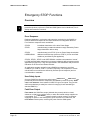
Emergency STOP Functions ................................................................................52
Overview............................................................................................................52
Error Response .............................................................................................52
User Safety Inputs.........................................................................................52
Fatal Error Output .........................................................................................52
Brake Output Option .....................................................................................53
Status and Display.............................................................................................53
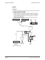
STOP 0 ..............................................................................................................54
Activation.......................................................................................................54
Execution.......................................................................................................55
STOP 1 ..............................................................................................................56
Activation.......................................................................................................56
Execution.......................................................................................................57
STOP2 ...............................................................................................................58
Activation.......................................................................................................58
Execution.......................................................................................................59
USER SIGNAL ..................................................................................................60
Activation.......................................................................................................60
Execution.......................................................................................................60
Fatal Error..........................................................................................................61
SAM Brake Option.............................................................................................61
Description ....................................................................................................61
Brake handling (brake enabled) ....................................................................62
Brake Object (class Cbrake) .........................................................................62
Parameters related to Brake Option .............................................................62
Brake behavior related to ENABLED field ....................................................63
Brake error ....................................................................................................63
Page: 4
SAM Configuration Manual
P/n 9031 011 987, November 14, 2000
SAM CONFIGURATION MANUAL
LIST OF FIGURES
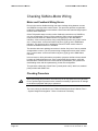
Checking SAM-to-Motor Wiring ............................................................................64
Motor and Feedback Wiring Errors ...................................................................64
Checking Procedure ..........................................................................................64
List of Figures
Figure 1
Figure 2
Figure 3
Figure 4
Figure 5
Figure 6
Figure 7
Figure 8
Figure 9
Figure 10
Figure 11
Figure 12
Figure 13
Figure 14
Figure 15
Figure 16
Figure 17
Figure 18
Figure 19
Figure 20
Figure 21
Figure 22
Figure 23
Figure 24
Figure 26
Figure 27
Figure 28
Figure 29
Figure 30
Figure 31
Figure 32
Figure 33
Figure 34
Figure 35
Figure 36
Figure 37
Figure 38
Multi-version structure..............................................................................9
SAM Tools Top Level Window...............................................................11
Control Panel with Component types Identified.....................................17
New Dialog Box......................................................................................19
Trace Commands Dialog Box ................................................................21
Trace Control Panel ...............................................................................22
Trace window .........................................................................................23
Test Device “Analog” panel....................................................................25
SAM Drive Software Functions ..............................................................26
Position Controller Functional Diagram .................................................27
Operating software Initialization phase ..................................................29
PD Position Controller............................................................................32
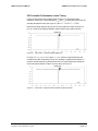
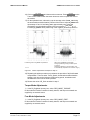
PD Control - Critically Damped Response.............................................35
PD Control - Over damped Response ...................................................35
PD Control - Under damped Response .................................................36
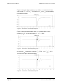
PID Control - Critically Damped Response............................................37
PID Control - Response with increased Cutoff Frequencies .................37
PID Control – Over-damped Response .................................................38
PID Control - Under-damped Response ................................................38
PID Control - Under-damped Response ................................................38
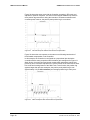
PD Axis Response without Feed-forward Compensation......................39
PID Axis Response without Feed-forward Compensation.....................40
PD Axis Respond with Feed-forward Compensation.............................40
Tuning Control Panel with Least Significant digit of M_Stop0_AB
Designated .............................................................................................44
Reference Waveforms for Proportional plus Derivative Tuning Step 17.
...............................................................................................................46
Example waveforms for Step 6. .............................................................48
Static friction compensation examples for step 8. .................................49
Viscous friction compensation examples for step 13.............................50
Inertia compensation examples for Step 17 ..........................................51
STOP0 Activation...................................................................................54
STOP0 Execution...................................................................................55
STOP1 Activation...................................................................................56
STOP1 Execution...................................................................................57
STOP2 Activation...................................................................................58
STOP2 Execution...................................................................................59
USER SIGNAL Activation ......................................................................60
STOP2 Execution...................................................................................60
Brake Option Functional Diagram..........................................................61
SAM Configuration Manual
P/n 9031 011 987, November 14, 2000
Page: 5
Figure 25
SAM CONFIGURATION MANUAL
LIST OF TABLES
List of Tables
Table 1
Table 2
Table 3
Table 4
Table 5
Table 6
Table 7
Table 8
Table 9
Table 10
Table 11
Table 12
Table 13
Table 14
Table 15
Page: 6
Description of Components of SAM Tools Main Window Components.11
SAM Tools Subdirectory and file extension conventions......................12
ACC Standard Upload Templates (vv = version number, i.e. all20xx.spa
for version 2.0) .......................................................................................14
ACC Standard Panels (not available in all software versions; refer to
\ACC\Socatool\Panels sub-directory content.) ......................................16
List of ACC Standard Traces .................................................................20
Most interesting variables to trace *) it represents the pipe_position of
PAM .......................................................................................................22
Short listing of Controller Parameters ....................................................32
Short listing of Controller Fields; Measured position and velocity values
(Mf_POS_MES and Mf_VEL_MES) are Main Sensor fields (and not
Controller fields). Their prefix is thus “Mf_”............................................33
Position Controller Modes......................................................................43
SAM Default action mask (valid only for System 2.0_2)........................53
Brake Object fields .................................................................................62
Brake Object parameters .......................................................................62
Brake Object behavior ...........................................................................63
Resolver Feedback and Motor Windings Wiring Verification Procedure
...............................................................................................................66
POS_RES Values for ACC AC Servomotors.........................................67
SAM Configuration Manual
P/n 9031 011 987, November 14, 2000
SAM CONFIGURATION MANUAL
INTRODUCTION
Introduction
Scope of this Manual
This SAM Configuration Manual presents procedures and guidelines for start-up of
a SAM Drive in a PAM and SAM environment.
Related Documents
The PAM and SAM System User’s Handbook (in 6 parts) documents the Hardware.
This SAM Configuration Manual contains information related to Software.
Intended Use of SAM Products
The SAM product line constitutes a Power Drive System according to international
standard IEC 611803, and Power Conversion Equipment according to UL standard
508C. Its intended use is for powering and controlling moving parts within industrial
machines. SAM products are supplied as subassemblies to professional
assemblers for incorporation into machines, apparatuses or systems. Assemblers
are responsible for insuring that the SAM products are used for their intended
purpose only, and for compliance with all applicable regulations.
According to the European Directive 80/392/EEC regarding machinery, putting a
SAM Power Drive System into service is prohibited until the machinery into which it
is to be incorporated has been declared in conformity with the provisions of this
Directive.
Personal Safety
The SAM product line is intended for connection to standard main voltages up to
480 VAC and for running motors up to 8000 rpm. High voltage and moving parts
can cause severe or fatal injury. ACC Motion and Inmotion Technologies provide
this and other manuals for assisting assemblers in using the products in a correct,
efficient and safe manner.
Assemblers must insure that all persons responsible for design, test, maintenance
and use of SAM have the proper professional skill and apparatus knowledge.
For compliance with the EC Directives and standards applicable to SAM products
assemblers must read, understand and apply the specified procedures and
practices regarding safety set forth in the PAM and SAM System User’s Manual (6
parts).
When modifying PAM and SAM System Software, parameters, variables or any other
configuration setting, the user must keep in mind that motors are powerful enough for
causing fatal injuries to humans, and severe damage to machines.
SAM Configuration Manual
P/n 9031 011 987, November 14, 2000
Page: 7
SAM CONFIGURATION MANUAL
INTRODUCTION
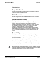
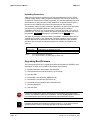
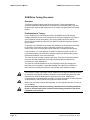
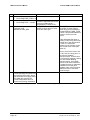
Warnings, Cautions and Information Notices
Special attention must be paid to the information presented in Warning, Caution
and Information notices when they appear in this manual. Examples of these
notices along with a description of their purposes follow:
i
STOP
An Information Box contains supplemental information or references to supplemental
information on a topic.
The Stop Box highlights important conceptual or procedural details that must be
understood and applied in order to successfully use the product.
A Warning informs the user of a hazard or potential hazard that could result in serious
or fatal injury if the precaution or instruction given in the Warning notice is not observed.
Page: 8
SAM Configuration Manual
P/n 9031 011 987, November 14, 2000
SAM CONFIGURATION MANUAL
SAM TOOLS
SAM Tools
Preliminary Remark
All software components that are required for running a PAM and SAM System are
supplied on the “ProMotion Collection” CD-rom. Each collection gathers several
versions, together with several utilities and documentation.
The ProMotion Help file provides also for comprehensive information about SAM
Tools.
Installing SAM Tools
PC Hardware Platform
Minimum PC Configuration Required
•
•
•
•
•
•
80486 processor
8 MB RAM memory
16 color VGA graphic adapter
1 serial port
15 MB disk space (for SAM Tools only), 30 MB for complete Promotion
package
Windows 95 or 98 installed
Recommended PC Configuration
•
•
•
•
•
•
Pentium processor
16 MB RAM memory
16 color SVGA graphic adapter
1 serial port
15 MB disk space (for SAM Tools only), 30 MB for complete Promotion
package
Windows 95 or 98 installed
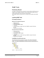
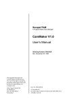
Installation for multi-version use
The hierarchical structure proposed to be able to have different PAM & SAM
systems and 32 bits new applications installed on a single PC is described in
Figure 1. It is sharply recommended to use this structure to get the best efficiency.
Struct2.bmp
Figure 1
SAM Configuration Manual
P/n 9031 011 987, November 14, 2000
Multi-version structure
Page: 9
SAM CONFIGURATION MANUAL
SAM TOOLS
How to migrate from an old structure to the new structure
If your previous installation does not correspond to this structure, proceed as follow:
1) Quit the installation program.
2) Launch File Manager.
3) Remove all old versions of ProMotion on the PC.
4)
•
•
•
•
•
Edit AUTOEXEC.BAT file and remove the following lines:
SET PAM=C: \SOCATOOL
SET PAMAGL=.
SET PAMSRCE=..\SRCE
SET PAMTEMP=C:\SOCATOOL\TEMP
SET PATH=xxx;C:\SOCATOOL (remove only the path to SOCATOOL)
5) Reboot the PC.
6) Restart the Master Setup.
During installation, a name for the root directory is requested. It must be as short
as possible to guarantee that the old versions are running properly. By default, this
directory name is “ACC”. Longer directory name should not be used.
How to install a ProMotion version
1) From the CD-Rom and Master Setup, choose the desired ProMotion version
and follow the instructions.
2) From the CD-Rom without the Master Setup, explore the CD-ROM, choose the
desired ProMotion version, open the directory called Disk1 and launch the
application SETUP.EXE
How to install a Service-Pack
A Service-Pack is an upgrade of a ProMotion version. It is designed for only one
version of ProMotion.
Proceed like a ProMotion installation. Be sure that you install the corresponding
Service-Pack.
How to install several ProMotion versions
1) If any ProMotion version is already installed with the new structure, rename the
“SOCATOOL” directory (with file manager) with an explicit name (i.e. V121 for
ProMotion version 121).
2) Install the new ProMotion version as usually.
3) To use older PAM & SAM systems, it is enough to rename the directory
«SOCATOOL» like above and to rename the selected directory in
«SOCATOOL»
How to install a Service-Pack on a structure with several ProMotion versions
Verify that the corresponding ProMotion version is installed and activated (The
directory SOCATOOL corresponds to the selected ProMotion version)
Page: 10
SAM Configuration Manual
P/n 9031 011 987, November 14, 2000
SAM CONFIGURATION MANUAL
SAM TOOLS
Setting up the COM Port
When SAM Tools is installed, COM1 port of the Service PC is selected by default.
To select COM port 2 perform the following:
For Windows 95 and 98:
1) Access SAM Tools, properties
2) Select shortcuts tab
3) Under target add “COM2” separated by a space
(i.e. xxxx\SAM TOOLS.EXE COM2).
Getting Started with SAM Tools
Top Level Window
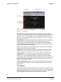
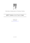
Status and Display Components
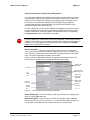
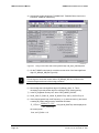
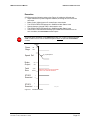
Figure 2 shows the SAM Tools top level Window with the status and display
components identified. Table 1 provides a description of these components.
Mainwin3.bmp
Figure 2
SAM Tools Top Level Window
component
link status display
Bootware Version display
Firmware version display
SAM Drive status display
log message display
menu bar
tool bar
Table 1
SAM Configuration Manual
P/n 9031 011 987, November 14, 2000
description
Displays status of SAM - Service PC communications
link at time of last handshake
Bootware version residing in SAM Drive
Firmware version residing in SAM Drive
Displays current SAM Drive operating state
Most recent log message from SAM Drive
Contains SAM Tools main pop-down menus
Contains buttons for activating SAM Tool functions.
Buttons for active functions appear in high contrast,
colors on non-active buttons are subdued
Description of Components of SAM Tools Main Window Components
Page: 11
SAM CONFIGURATION MANUAL
SAM TOOLS
Tool Bar
When the mouse cursor is placed on an icon, a brief description of the buttons is
displayed in a box.
SAM Tools Subdirectories and File Extensions
During installation SAM Tools creates a number of subdirectories at the directory
specified by the user at the beginning of the installation procedure. Different types
of files as described in Table 2 are deposited into each of the subdirectories. ACC
recommends retaining this structure as well as the file extension defined for each
file type because software upgrades and revisions rely on this file structure.
sub directory name
firmware
bootware
params
panels
cmds
support
symbols
help
temp
Table 2
ext.
.sfi
.sbi
.spa
.pan
.stc
.shc
.syd
description
SAM Drive firmware files
SAM Drive bootware files
SAM Drive and motor parameter files
Creation files for ACC standard panels
ACC standard trace commands files
host commands files (up to version 1.3)
conversion utility and C++ example programs
symbols dictionary
on-line help files
temporary workspace for files created during
SAM Tools execution
SAM Tools Subdirectory and file extension conventions
We recommend that users create separate directories utilizing the same
subdirectory and file extension structure for storing and archiving user-created
parameter, panel and trace files.
Page: 12
SAM Configuration Manual
P/n 9031 011 987, November 14, 2000
SAM CONFIGURATION MANUAL
SAM TOOLS
Parameters
SAM Tools provides the capability to download parameter files to a SAM Drive and
upload parameters from a SAM drive into a file on the Service PC. The parameter
upload and download features provide the means for recording, saving and
replicating axis (software) configurations.
Downloading Parameters
Parameters are downloaded into SAM Drive RAM memory where they remain until
changed by command from a host PC/PLC or SAM Tools via the service port. Upon
resetting the SAM Drive or upon power-up all parameters are initialized to values
saved in flash memory.
Upon receipt of a “save parameters” command, the drive firmware copies an image
of all parameters from RAM into flash memory. Parameter value changes are
immediately accessible to the drive firmware; however, the firmware uses certain
parameters only during initialization.
STOP
To be saved, parameters have to be copied into the flash memory using the “SAVE”
command in the “Parameters” menu. Doing that, existing parameter values are
overwritten and lost.
Existing SAM Drive parameter values may be preserved by uploading them to the
service PC prior to downloading new parameters..
Motor Parameters
Motor parameters must be downloaded to properly configure a SAM Drive for the
motor it is controlling. To insure that a SAM Drive is properly configured for the
motor it is controlling, this procedure should be performed whenever a SAM Drive
is installed in a SAM system or whenever existing motor parameters are invalid or
suspect.
i
When downloading motor parameters, be certain to select the correct file for the motor
model connected to the SAM Drive.
Downloading incorrect motor parameters may cause unpredictable motor or drive
behavior, and possibly be harmful to the drive or motor.
Application related Parameters
Some parameters related to the application (position controller parameters, etc.)
have to be tuned to obtain the best performances of the system. Refer to SAM
Drive Tuning Procedure on page 42 for tuning procedure.
SAM Configuration Manual
P/n 9031 011 987, November 14, 2000
Page: 13
SAM CONFIGURATION MANUAL
SAM TOOLS
Uploading Parameters
SAM Drive configurations (parameter sets) may be uploaded to a Service PC for
viewing, editing, saving or other purposes using SAM Tools. During an upload, the
complete set of parameters in RAM is uploaded. The uploaded parameter set when
downloaded to an identical (same model) SAM Drive configures the drive exactly
the same as the SAM Drive from which the parameter set was extracted.
The parameter values currently in RAM are uploaded to the Service PC where they
are saved in the PARAMS subdirectory. SAM Tools assigns the filename
“PARAMxxx.SPA where xxx is incremented by one each time SAM Tools saves a
parameter set. The user may rename and relocate uploaded parameter sets using
the standard SAVE AS... Windows file commands from the FILE
menu.
Two types of parameter upload procedure are available; a standard upload and an
“Upload with Template. In the “Upload with Template” operation, a user-created
template attached to the parameter file controls which parameters are uploaded
and which are not. Some pre-defined templates are available in ProMotion (see
Table 3).
file name
allvvxx.spa
appvvxx.spa
Table 3
upload
all parameters in alphabetical order
all parameters except drive specific ones
ACC Standard Upload Templates
(vv = version number, i.e. all20xx.spa for version 2.0)
Upgrading Boot/Firmware
The following procedure is for upgrading bootware and firmware of SAM Drive (see
Initialization on page 30 for definitions of bootware and firmware).
1) Upload parameters with template App15XX.SPA.
2) Save parameters as contextual name (e.g. Axis3.spa).
3) Stop the SAM.
4) Download the new bootware (SBEZxxxx.sbi).
5) Download the new firmware (SFEZxxxx.sfi)
6) Download saved parameters with contextual name.
7) Save all parameters.
8) Start the SAM.
STOP
i
Page: 14
If a 24 VDC supply failure occurs during wring of the bootware program into flash
memory, the SAM Drive will become inoperative, requiring factory repair. Therefore,
we recommend this procedure be performed only when absolutely required.
Upgrading bootware and firmware from System version 1.2_xx or older requires a
special procedure. Refer to Promotion.hlp help file for more information.
SAM Configuration Manual
P/n 9031 011 987, November 14, 2000
SAM CONFIGURATION MANUAL
SAM TOOLS
Replacing a SAM drive
To be able to change a SAM drive in good conditions, it is recommended to have a
saved parameters file of each axis. To create such a file, the following procedure is
used.
1) Upload parameters with template App20XX.SPA.
2) Save parameters as contextual name (e.g. Axis3.spa).
Then its is very simple to change a SAM drive. Proceed as described in the “PAM
and SAM System End-User’s Manual”.
i
If parameters are managed within the PAM application, this procedure is not necessary.
i
When replacing simultaneously the SAM software version, more information is available
in ProMotion Help “How to install a new SAM System” topic”.
Control Panels
Overview
A particularly powerful and useful feature of SAM Tools is the capability to create
custom control panels on the Service PC monitor. Control panels provide direct,
simplified access to a SAM Drive via the service port for tasks such as testing,
monitoring or servicing an axis. Panels may be customized to the extent that
buttons and displays have customized legends relevant to the machine or
application or language of the country where used. Control panel attributes are
stored in software files permitting control panels to be stored, recalled and
recreated as needed.
A control panel is a customizable graphical interface to the SAM Drive, which
provides the capability to interrogate and manipulate SAM parameters and fields.
SAM Tools software provides the interface between a control panel and a SAM
Drive, converting operator and actions to the appropriate commands and updating
the panel based on the drive’s responses.
SAM Configuration Manual
P/n 9031 011 987, November 14, 2000
Page: 15
SAM CONFIGURATION MANUAL
SAM TOOLS
ACC Standard Control Panels
ProMotion includes a library of standard panels useful for various aspects of SAM
system monitoring, tuning and control. A description of the ACC standard panels is
found in Table 4. These standard panels may also be used as the starting point for
a user creating customized panels for a specific application.
file name
analog.pan
brake.pan
endat.pan
hardinfo.pan
init_loc
init_mon
init_pol.pan
io.pan
magnali.pan
main.pan
mask.pan
mot_enco.pan
motor.pan
move.pan
msampler.pan
regcur.pan
regsamp.pan
resolver.pan
sap_all.pan
sensor.pan
stat_ab.pan
stat_cd.pan
st_com.pan
st_enco.pan
st_main.pan
st_mes.pan
status.pan
t_device.pan
temper.pan
torq.pan
tst_move.pan
tuning.pan
z_mark.pan
Table 4
used to
define which variables to convert in analog outputs on Test Device
check brake behavior
display EnDat features of multiturn encoders and resolvers
display hardware information
check and initialize local position
nd
check and initialize 2 position feedback
check linear and some direct drive motors (System 2.0 and up)
check and configure I/Os
check linear and some direct drive motors (System 1.3 and 1.5)
check general behavior
define Status Masks
special panel for motors fitted with an sine-cosine encoder
view (and modify) motor parameters
define and run repetitive movements on motor (System 1.3 and 1.5)
check SAM interface to PAM-emitted position trajectory
check Current Controller parameters
display fast input sampling
check resolver and motor wiring and setting
display all SAM application variables
display and define all feedback settings
display Status A and B
display Status C and D
display EasyBus communication status
display Sine-Cosine encoder status
display Main Status (status_m.pan on 1.3; statmain.pan on 1.5)
display internal resolver status (statmes.pan on Syst. 1.3 and 1.5)
display all status fields
define which variables to convert in analog outputs on Test Device
display temperatures and voltages
display and define SAM in Torque mode
define and run repetitive movements on motor (Syst. 2.0 and up)
check and adjust Position Controller parameters
display reference mark of encoders
ACC Standard Panels (not available in all software versions;
refer to \ACC\Socatool\Panels sub-directory content.)
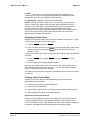
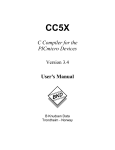
Control Panel Components and their Operation
This section describes the components of a control panel and their operation.
Figure 3 illustrates a sample control panel containing each of the available control
panel component types with each component type labeled. Each of the panel
component types is described in the following paragraphs.
Page: 16
SAM Configuration Manual
P/n 9031 011 987, November 14, 2000
SAM CONFIGURATION MANUAL
SAM TOOLS
General Instructions for Control Panel Dialog Boxes
For most types of dialog boxes, SAM Tools places a border around the box when it
has been opened and no other operations are allowed until the box is closed. The
border color is red initially and changes to blue when the value is changed. Once
the content of a box has been changed, press the ENTER key to update the
corresponding SAM Drive parameter/field, or press ESC (the ESCAPE key) to
restore the original value and exit the box.
In order to display the current value of SAM Drive fields/parameters a control panel
must be updated. Control panels are automatically updated when initially opened
and when reactivated. A user may update a control panel at any time by pressing
the REFRESH PANEL button on the SAM Tools toolbar.
STOP
In order to display the current value of fields and parameters, a control panel must be
updated. Control panels are automatically updated when initally opened and when reactivated. A user may update a control panel at any time by pressing the REFRESH
PANEL button on the SAM Tools tollbar.
Numeric Entry Box - This type of box accepts numeric values. To change the
value, click inside the box, then modify the existing value or enter a new value. The
units of numeric entry boxes are the units of their corresponding fields in the SAM
Drive. The units are generally included in the box label.
Numeric values are displayed in decimal, hexadecimal and scientific format. The
format used is a function of the corresponding field and panel setup.
Buttons with
argument
List box
Buttons with
fixed argument
List
combo
box
Button with
adjustable
argument
Button with
dual action
Numeric
entry box
Boolean
entry box
Status
display
box
Figure 3
Sconf004.cdr
Control Panel with Component types Identified
Status Display Box - These are single bit, read-only boxes used for displaying the
value of a single SAM Status bit.
Boolean Entry Box - This type of box is used for controlling the state of Boolean
inputs, which can only be true or false. An “x” in the check box means the input is in
it’s true state, and a blank check box means the input is in it’s false state.
SAM Configuration Manual
P/n 9031 011 987, November 14, 2000
Page: 17
SAM CONFIGURATION MANUAL
SAM TOOLS
List Box - The value of the corresponding field/parameter highlighted in a
contrasting color. Select an item from the drop-down list displayed in the box
changes the value; then press ENTER on the keyboard.
List Combo Box - Displays a pop-down list of selections.
Button - Clicking on a button initiates one or more specific, pre-programmed
actions. A button may operate in any of several ways depending on how it is
specified in the control panel. The possibilities (see Figure 3) include buttons
having no argument, buttons with fixed arguments (built into the button
specification), buttons with an adjustable argument whose value is taken from a
numeric entry box, and dual action buttons which produce an action when
depressed and an action when released.
Activating a Control Panel
Opening its file from the SAM Tools Log window activates a control panel. To open
a control panel file, perform the following steps:
1) From the
FILE
menu select
OPEN
,
2) In the “File Open” dialog box, select the file name (including path) of the control
OK
panel to be activated, then press
extension “.PAN”.
. All control panels have the file
If the desired control panel is listed on the SAM Tools recall list, it may be accessed
as follows:
1) From the
submenu.
FILE
menu, select
RECALL
, then select
PANELS
from the
2) From the pop-down list, select the desired panel.
More than one control panel may be open at a time, but only one panel may be
active and only the active panel is responsive. The user may change the active
panel by clicking in the panel to be activated.
The display boxes on a panel are updated automatically when the panel is opened
or activated.
Creating a New Control Panel
Creating a new control panel is a straightforward process, which requires
performing the following steps:
1) Determine the functions required of the panel
2) Open a new panel document
3) Create buttons, displays and numeric entry boxes and specify their operation
4) Add any custom labeling or nomenclature desired.
Determine the Functions Required
Panels are usually created for performing a specific task and include only those
controls required for the task. This approach simplifies creation and use of the
panel. The ProMotion Help, “SAM Parameters & Fields” topic provides a listing and
description of all SAM Drive fields and parameters accessible by panel.
Page: 18
SAM Configuration Manual
P/n 9031 011 987, November 14, 2000
SAM CONFIGURATION MANUAL
SAM TOOLS
Although functions to stop motion and disable a SAM Drive output may be included on
a panel, these functions cannot be considered “safe” as defined in IEC 60204-1 or IEC
61803. Safety functions must be implemented as specified in the PAM and SAM
System User’s Handbook, Part 3 – Safety and Protective Functions.
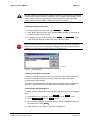
Opening a New Panel Document
1) From the SAM Tools Log window, select
FILE
then
NEW
.
2) In the “NEW” dialog box (see Figure 4) select PANEL DOCUMENT. A new window
containing a blank panel is opened.
SAVE AS
3) To assign a file name to the panel file, select FILE
then
“FILE SAVE AS” dialog box, enter a file name and select a path.
STOP
. In the
When a new panel document is created, the panel window is opened in “Edit Mode”,
which is the correct mode for creating and modifying panels. When utilizing a panel
window as a control panel, the panel must be in “Execute Mode”.
Sconf011.cdr
Figure 4
New Dialog Box
Creating Control Panel Components
Creating control panel components is a menu driven process in which buttons and
boxes are created by selecting from a list of parameters, fields and methods
accessible from control panels.
The nature of a field/parameter selected dictates the type(s) of entry or display box
created. For buttons, the selected method dictates the button type(s) created.
Creating Entry and Display Boxes
To create an entry or display box in an open Panel document, perform the following
steps:
1) If the panel is not in “Edit Mode”, select
2) Select
NEW CONTROL
from the
PANEL
EDIT
from the
PANEL
menu.
menu.
3) Using the Object Browser, locate and select the field or parameter to insert into
the control panel. Press
OK
.
4) In the “Choose Control Type” list box select a display box
SAM Configuration Manual
P/n 9031 011 987, November 14, 2000
Page: 19
SAM CONFIGURATION MANUAL
SAM TOOLS
Trace
One of the most useful features of SAM Tools is its trace capability. The behavior of
up to up to four SAM variables as a function of time may be captured, displayed,
printed or saved for reference purposes. Trace setup information including trigger
point specifications, sampling rate and trace variables are defined in a Trace
Command file created using SAM Tools. Trace data is captured and saved in a
reserved segment of SAM RAM memory, then uploaded on command to the
Service PC where it may be displayed or saved and displayed at a later time.
The trace trigger point is defined by an expression, which may be a combination of
numerical and logical values and operators. As with most digital storage
oscilloscopes, the trace tool may be configured to display data before and after the
trigger point. The sampling rate is adjustable over a wide range of values from
processor cycle rate (8 kHz) to 1 (one) Hz.
ACC Standard Trace Setups
The ProMotion includes a number of standard Trace command files for creating the
Trace setups referenced in this manual. A description of these ACC standard trace
setups in found in Table 5. These standard traces may also be used as the starting
point for users creating custom traces for specific applications.
file name
marker.stc
regcur.stc
regpos.stc
resolver.stc
resshift.stc
setpoint.stc
speed.stc
st_ab.stc
st_cd.stc
tetapos.stc
timing.stc
tmagn20.stc
trace_io.stc
tuning.stc
Table 5
description
trace SAM application markers
current regulation
used with tuning.pan to adjust feed-forward components of the
Position Controller
display resolver signals
display resolver interface voltages
display set point from PAM
display speed reference
display status AB
display status CD
display measured position and polar angle
display internal SAM tasks duration
display polar angle teach-in sequence
display inputs
used with tuning.pan to adjust gains of the Position Controller
List of ACC Standard Traces
Producing a Trace
This paragraph describes the procedure for setting up a Trace using an existing
Trace Command file:
1) From the Log window’s
DEVICE
menu select
TRACE COMMANDS
.
LOAD
. In the
2) In the “Trace Commands” dialog box (see Figure 5) press
“Open” dialog box, select the subdirectory containing the trace commands file
to be utilized. Trace Command files have the file extension “.STC”. Click
OK
Page: 20
.
SAM Configuration Manual
P/n 9031 011 987, November 14, 2000
SAM CONFIGURATION MANUAL
SAM TOOLS
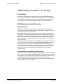
3) The selected trace command file (see Figure 5) is now displayed in the “Trace
Commands” dialog box. It defines for each channel, the label and the type, the
address and the size of the variable to display. Table 6 shows the type and the
size of the most interesting variables to trace. For addresses, as they are
related to the firmware version, please use the browser for the DSP variables
or refer to the “ProMotion.hlp” help file for the i960 variable. A “Trace” control
panel (see Figure 6) is also displayed.
EXECUTE
4) In the “Trace Commands” dialog box press
to setup the SAM
Drive for capturing the trace data. The message “Execution Successful”
appearing in the “Trace Commands” dialog box indicates successful setup of
the SAM Drive.
CLOSE
5) Press
to close the “Trace Commands dialog box.
6) In the “Trace” control panel, press
START
to initiate the trigger.
7) When the Trace control panel displays TRIGGERED and STOPPED the trace data
UPLOAD
gathering operation is complete. On the “Trace” control panel press
to upload the trace data to the Service PC for display. The trace data is also
saved to a file in the TEMP subdirectory. SAM Tools assigns the name
“TRACExxx.TRC (where xxx is the next number in sequence) to the trace file.
8) To initiate another trace operation utilizing the same trace setup, first press
on the SAM Tools toolbar to recall the “Trace” control panel, then press
START
Figure 5
SAM Configuration Manual
P/n 9031 011 987, November 14, 2000
to initiate another trace operation.
Trace Commands Dialog Box
Page: 21
SAM CONFIGURATION MANUAL
SAM TOOLS
Figure 6
Trace Control Panel
Related Field
Rf_SPEED_REF
Rf_ACCEL_REF
Rf_POS_LAG_16
Rf_TORQ_FLOW
Rf_TORQ_QUIET
Rf_TORQ_REF
Rf_IKAN
Af_UDCBus
Af_IQRef
Af_IQMes
Mf_SIN_A
Mf_COS_A
Mf_POS_RES
Of_INPUTS_VALUES
none*
Table 6
Symbol
SpeedRef
AccelRef
PosLag
TorqFlow
TorqQuiet
TorqRef
Ikan
UdcBus
IQRef
IQMes
Sina
Cosa
PosResB
Inputs
Setpoint
Mem. Type
MEM_DSP_INT
MEM_DSP_INT
MEM_DSP_INT
MEM_DSP_INT
MEM_DSP_INT
MEM_DSP_INT
MEM_DSP_INT
MEM_DSP_INT
MEM_DSP_INT
MEM_DSP_INT
MEM_DSP_INT
MEM_DSP_INT
MEM_DSP_INT
MEM_960
MEM_960
Type
INT16
INT16
INT16
INT16
INT16
INT16
INT16
INT16
INT16
INT16
INT16
INT16
INT16
BIN16
INT32
Units (1 lsb = …)
0.915 t/min @ 8kHz
2
3433.23 t/min @ 8kHz
-16
2 t
4096 = stall Torque
4096 = stall Torque
4096 = stall Torque
4096 = Udc max
4096 = Imax
4096 = Imax
-16
2
t
-6
27.94·10 t/min
(CPU=2kHz)
Most interesting variables to trace
*) it represents the pipe_position of PAM
Units depending on the working frequency (4 or 8 kHz) are calculated as follow:
SpeedRef given units in the filed list: 2-19 t/POS REG period
we have then, at 8 kHz:
2 −19
• 60 = 0.915turn / min
1
8000
(
)
AccelRef given units in the filed list: 2-26 t/POS REG period
we have then, at 8 kHz:
2 −26
(18000)
2
• 60 2 = 3433.23turn / min 2
Setpoint units are 2-32 t/MAIN CPU period. MAIN CPU period is 2 kHz then:
2 −32
• 60 = 27.94 • 10 − 6 turn / min
1
2000
(
)
Interpreting and utilizing the Trace Display
The trace display includes a number of useful features and capabilities to aid in
measuring and analyzing the captured data including movable markers, an optional
grid and zooming capability.
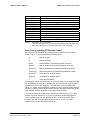
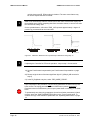
Components of Basic Trace Display
This paragraph provides a description of the components of a trace and how they
are utilized and interpreted. Figure 7 shows a two variables trace with components
identified.
Page: 22
SAM Configuration Manual
P/n 9031 011 987, November 14, 2000
SAM CONFIGURATION MANUAL
SAM TOOLS
Trigger point
Trigger position
Channel title
Variable scales
(auto-adjusted)
Chanel
graphical area
Figure 7
Time scale
Sconf005.cdr
Trace window
Time Scale - Shows the time reference for the trace data. The time scale is a
function of the sample rate specified in the Trace Command file associated with the
trace data. Time t = 0 is the trigger point (point at which the trigger condition is
satisfied). The pre and post trigger percentages displayed are set by command in
the Trace Command file.
Variable Scale - The graphical display of each variable is adjusted automatically to
show the full excursion of the variable over the sampling interval within the
available vertical space and the variable scale shows the relationship between
vertical amplitude of the variable and it’s actual value. Units of the variable scale
are the units of the variable (see Table 6).
Note that the variable scale for successive traces of a variable may be different if
the total excursion of the variable changes.
Trigger Point - This dashed vertical line indicates the point at which the trigger
condition is satisfied. This point becomes the time origin (t = 0) for the trace.
Trigger Position - The position (or value) of each variable at the trigger point.
Channel Title - This is a four part expression comprised of a channel label,
memory type, memory address and data type. Channel label is a user-defined
name for the variable, memory type and memory address define the location of the
variable is the SAM Drive’s RAM memory and data type defines the format (i.e.
integer, real, etc.) of the variable.
Channel Graphical Area - Portion of the channel in which trace data is plotted.
The areas at the left and right extremes of each channel graph are outside the
graphical area.
Trace Markers
Two trace markers (M1 & M2) are available for making precise measurements from
graphical trace data. The value of each variable at it’s point of intersection with the
marker is displayed along with the position (it time) of each marker. In addition the
delta t and delta values for each channel are displayed on the trace.
SAM Configuration Manual
P/n 9031 011 987, November 14, 2000
Page: 23
SAM CONFIGURATION MANUAL
SAM TOOLS
To position a trace marker on a displayed trace, position the mouse pointer over
the desired point, hold down the SHIFT key, then click on the left or right mouse
button (left button to position M1 or right button for M2). Markers are not saved
when a trace file is closed.
Markers may be alternately hidden or shown by selecting
VIEW
menu.
MARKER
from the
Grid
A grid may be alternately applied or removed from the graphical display area of a
trace by selecting GRID from the VIEW menu.
Trace Zoom Feature
The zoom feature may be used to magnify a portion of a trace, Two zoom modes,
time zoom and area zoom are available. Time zoom takes a selected portion of the
trace and expands it horizontally to fill the trace display area. Area zoom expands
the selected area of a single channel to fill the display area. When a trace is
expanded the time and variable scales are adjusted accordingly to retain a
calibrated image. Any sector of a trace within the graphical area of a channel may
be zoomed. When zooming is possible a magnifying glass symbol is displayed
beside the mouse pointer. Zoomed traces may be printed but not saved.
Perform the following steps to time zoom a trace:
1) Position the mouse pointer inside the graphical area of a channel at one end of
the area to be expanded. The magnifying glass symbol must be visible next to
the mouse pointer indicating that zooming is possible.
2) Press and hold the left mouse button.
3) While holding the mouse button down, move the mouse pointer left or right and
up or down as necessary to “box in” the area to be expanded.
4) Release the mouse button. An expanded display of the selected area is
created.
5) To return to the previous version of the trace select PREVIOUS from the
VIEW
menu. To return to the original version of the trace, select ORIGINAL
from the VIEW menu.
In order to zoom on area of a trace, perform the following steps:
1) Position the mouse pointer inside the graphical area of a channel at one corner
of the area to be expanded. The magnifying glass symbol must be visible next
to the mouse pointer indicating that zooming is possible.
2) Press and hold the right mouse button.
3) While holding the mouse button down, move the mouse pointer left or right to
the other end of the area to be expanded. As the pointer is moved a box
encloses the selected area.
4) Release the mouse button. An expanded display of the selected area is
created.
5) To return to the previous version of the trace select PREVIOUS from the
VIEW
menu. To return to the original version of the trace, select ORIGINAL
from the VIEW menu.
Page: 24
SAM Configuration Manual
P/n 9031 011 987, November 14, 2000
SAM CONFIGURATION MANUAL
SAM TOOLS
Test Device
The SAM Test Device is an optional tool, which can be inserted between the SAM
RS232 servicing plug and the Service PC cable. With this device, two internal
variables can be available on two analog outputs, i.e. for monitoring on an
oscilloscope.
The “analog.pan/t_device.pan” panel (see Figure 8) allows selecting which variable
is displayed on which output.
Set the DSP variable described
below to the analog output 1
Set the i960variable described
below to the analog output 1
Set the DSP variable described
below to the analog output 1
Set the i960variable described
below to the analog output 1
Sconf006.cdr
Figure 8
Test Device “Analog” panel
DSP variables can be selected directly within the scrolling list.
i960 variables have to be defined with their addresses and their size (see
ProMotion.hlp, “Trace information” section).
For both types of variable (DSP and i960) the scale factor (units/volts) has to be
defined as in following examples:
SpeedRef given units in the filed list are
-19
2 t/POS REG period
which give at 8 kHz: 0.915 t/min.
It means that 1 lsb of the SpeedRef variable represents 0.915 t/min. Then, if we
want, for example 1V/1000 t/min, scale factor will be:
1000
= 1092.26units / volt
0.915
PosLag given units in the filed list are
-16
2 t
-3
which give: 5.49 10 degree.
-3
It means that 1 lsb of the PosLag variable represents 5.49 10 degree. Then, if we
want, for example 1V/1deg, scale factor will be:
1
= 182units / volt
5.49 • 10 −3
SAM Configuration Manual
P/n 9031 011 987, November 14, 2000
Page: 25
SAM CONFIGURATION MANUAL
SAM OPERATING SOFTWARE
SAM Operating Software
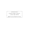
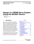
Introduction
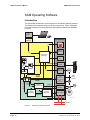
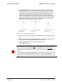
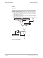
The functionality of SAM Drive comes largely from its resident operating software.
The functions are distributed among its two microprocessors. Figure 9 highlights
the principal software functions and shows links between software and hardware
functions.
Test
Device
SAM Tools
RS232
Interface
Hardware
Display
User I/O
(Option)
Commands
Manager
Motion Generator
standard
I/O
Fiber Optic
Interface
Σ
Socapel PAM
M
l
Brake Ctrl
(Option)
Safety
i960
Status
Traces
Pos / Vel / Acc
Reference
DSP
Pos / Vel
User
safety
circuits
3 IN
(Stop0,Stop1
motor overtemp.)
1OUT
(Fatal Error)
CMD
Position
Measurement
Brk.
Position
Position
Feedback
Interface
R/E
R/E
Magn. Pos.
Position
Regulator
Torque
Reference
Current
Regulator
Power Stage
M
Current Measure
SAS028_A.cdr
+
- DC Bus
Figure 9
Page: 26
SAM Drive Software Functions
SAM Configuration Manual
P/n 9031 011 987, November 14, 2000
SAM CONFIGURATION MANUAL
SAM OPERATING SOFTWARE
Definitions
Commands Manager
The Commands Manager handles communications with PAM, application program
(Sequence) execution and coordinates activities within the SAM. Using a dedicated
RS-232 port, it communicates with a PC running SAM Tools and a “Test Device”
accessory.
Motion Generator
The Motion Generator executes those portions of various pipe block functions,
which are implemented at the axis level. Secondly, it generates independent motion
profiles including point to point and continuous motions in response to commands
and parameters from the application program.
A “Limiter” compares the flow of motion data against limiting values of positive and
negative travel, speed, acceleration/deceleration, torque and direction imposed by
the application. Whenever a trajectory values exceeds a limit, the limiter sets an
appropriate status bit, which is normally used to stop the motion. The user normally
establishes limiter parameters, based on the application’s requirements.
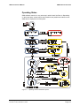
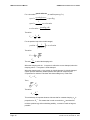
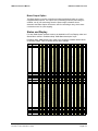
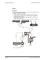
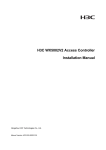
Position Controller
The Position Controller (see Figure 10) is a firmware algorithm that provides field
proven, closed loop PID control with enhanced feed-forward compensation. A notch
filter, which can be activated and tuned by parameter, may be utilized to improve
system performance in the presence of strong torque disturbances when a
mechanical resonance frequency might otherwise limit the closed loop pass-band.
The Position Controller, employing totally digital techniques, provides the benefits
of precision and repeatability. Two SAM Drives with identical tuning parameters
respond identically in the same axis environment.
Other Controller operating modes including speed controller, open-loop vectorcontrolled operation and direct torque control can be selected. A position feedback
device (typically a resolver or encoder) provides velocity and position feedback to
the Position Controller.
Position Regulator
1
0
PID
Position & Velocity
measured values
Error Status
notch filter
torque limiter
lag
max
min
Torque
Reference
Proportional Gain
Integral Gain
Derivative Gain
Position & Velocity
set points
Torque
set points
Feed
Forward
Inertia
Static Friction
Viscous Friction
Weight
SAS006_bCDR
Figure 10
SAM Configuration Manual
P/n 9031 011 987, November 14, 2000
Position Controller Functional Diagram
Page: 27
SAM CONFIGURATION MANUAL
SAM OPERATING SOFTWARE
Position Measurement
The Position Measurement function, utilizing input from the Feedback Interface,
provides measured position and velocity data. Position feedback is used by the
Current Controller for commutating the motor currents and by the Position
Controller for regulating motor speed and position.
Current Controller
The Current Controller is a closed loop controller, which supplies a three-phase
pulse width, and sine wave modulated current command to the Power Stage. It
monitors the output currents and regulates the direct (ID) and transverse (IG) current
components. The Current Controller employs totally digital control, which provides
improved performance and repeatability compared to standard analog technology.
Control algorithms for AC synchronous motors (AC Servo motors) and
asynchronous motors (AC induction motors) are built in and selectable by
parameter.
A downloadable parameter file, which correctly configures the Current Controller
and Power Stage, is available for every model servomotor that is available together
with the PAM and SAM System. Configuration files for other types of motors are
also available.
Built-in thermal load modeling of the axis motor utilizing motor and drive
parameters provides reliable and responsive motor overload protection under all
operating conditions.
Status Registers
Four 16-bit status registers provide a complete picture of SAM current operational
state with respect to error, fault and alarm conditions. For easier and quicker event
detection, a fifth 16 bit Main Status register provides a summary picture of SAM
current operational state.
Page: 28
SAM Configuration Manual
P/n 9031 011 987, November 14, 2000
SAM CONFIGURATION MANUAL
SAM OPERATING SOFTWARE
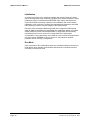
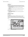
Operating States
SAM software controls in a very strict way in which “state” the Drive is. Depending
on the actual state, several actions and transitions are possible and others are not.
SAM state is displayed on its front-panel.
Figure 11
SAM Configuration Manual
P/n 9031 011 987, November 14, 2000
Operating software Initialization phase
Page: 29
SAM CONFIGURATION MANUAL
SAM OPERATING SOFTWARE
Initialization
A compressed version of the operating software (also named “Firmware”) along
with an uncompressed copy of a Boot-up program (also named “Bootware”) and all
parameters reside in nonvolatile flash EEPROM. Upon startup, the Bootware is
copied into RAM and executed. It performs some hardware and communication
initialization, then copies the Firmware (decompressed) and parameters into RAM.
CRC checking is used to verify the integrity of the RAM contents.
Execution of the operating software begins with the Configuration phase during
which all SAM Drive adjustments and settings are established digitally using either
default parameter values from flash EEPROM, or configuration files previously
downloaded from a host or service PC running SAM Tools. SAM may be
commanded to “save” parameters, upon which the current values of all parameters
are stored in flash EEPROM. A host or service PC may upload a complete
parameter set for archiving a configuration.
Run-Mode
Upon completion of the Configuration phase, the operating software enters the runmode phase, which handles communication with the host, commands execution
and finally controlling the motor.
Page: 30
SAM Configuration Manual
P/n 9031 011 987, November 14, 2000
SAM CONFIGURATION MANUAL
SAM POSITION CONTROLLER - ITS TUNING
SAM Position Controller - Its Tuning
Introduction
Section titled “SAM Position Controller Principles” discusses and illustrates the
concepts, terms and equations utilized in the tuning procedures. A block diagram
and description of the Position Controller is included in this introductory section.
This chapter presents next step by step procedures for tuning a SAM Drive.
SAM Position Controller Principles
Short Description
SAM Drives incorporate a modern, flexible closed-loop controller (called the
“Controller” or “Position Controller”) which is responsible for keeping an axis on it’s
required speed and position trajectories.
Closed-loop control is required for compensating indeterminate disturbances
(disturbances of unpredictable magnitude or timing). If indeterminate disturbances
are significant relative to the required accuracy, only comparatively high PID loop
gains can provide the necessary precision. However, with higher PID loop gains
comes the classic compromise of precision vs. stability. Position overshoots are
also very common.
The effects of known disturbances such as inertia (during acceleration), friction and
others are most easily eliminated using feed-forward compensation rather than
high position loop gain. If indeterminate disturbances are small, the required
accuracy may be achieved mainly using feed-forward compensation with lower
controller loop gains and less chance for stability problems. The integral gain can
also be set to zero, as in a simpler PD control scheme, so that no position
overshoot occurs.
Software Objects regarding Position Control
The Controller is software based and employs digital signal processing techniques.
The Controller is tuned by adjusting its parameters to achieve desired performance.
Using standard control panels and traces supplied with SAM Tools, drive tuning is
accomplished quickly and easily following the procedure in this chapter.
Figure 12 shows a functional diagram of the Position Controller. Parameters and
fields accessible to the user are labeled.
SAM Configuration Manual
P/n 9031 011 987, November 14, 2000
Page: 31
SAM CONFIGURATION MANUAL
SAM POSITION CONTROLLER - ITS TUNING
R_MaxPosLag
Sf_STATUS_AB
(Bit 0)
1
Mf_POS_MES
0
R_PGain
Rf_POS_REF
Σ
Rf_POS_LAG
R_MaxTorq
Ampli
Rf_TORQ_REG
Σ
Rf_TORQ_QUIET
max
Σ
Rf_TORQ_REF
min
R_MaxVelLag
1
Mf_VEL_MES
0
Sf_STATUS_AB
(Bit 0)
R_DGain
Rf_VEL_REF
(Rf_SPEED_REF)
Σ
Rf_VEL_LAG
Ampli
R_StatFricTorq
+F
-F
R_ViscFricTorq
Ampli
R_ExtTorq
Σ
Rf_TORQ_FEEDF
Ampli
Rf_ACC_REF
(Rf_ACCEL_REF)
R_Inertia
Rf_TORQ_FLOW
Rf_FLOW
3
Rf_FLOW_DESTINATION 21
0
Figure 12
Sconf001.cdr
PD Position Controller
A short listing and description of Controller parameters is found in Table 7, such as
set gains, thresholds or clamping limits for various functional elements of the
Controller. Detailed list is available in ProMotion Help “SAM Parameters and
Fields” topic.
The more dynamic Controller input and output variables are defined as fields, and
presented in Table 8.
All Controller parameters begin with the prefix “R_” or “Ri_” (e.g. R_PGain).
Controller fields prefix is Rf.
parameter name
R_DGain
R_ExtTorq
R_IGain
R_Inertia
R_MaxPosLag
R_MaxTorq
R_MaxVelLag
R_PGain
RStatFriqTorq
RViscFricTorq
Ri_RegMode
Table 7
Page: 32
description
sets derivative gain of controller
torque input when controller is in external command mode
integral gain of controller
sets inertia feed-forward compensation gain
sets threshold value for position lag error
sets upper torque limit
sets threshold value for velocity lag error
sets proportional gain of controller
sets static friction torque feed-forward compensation value
sets viscous friction torque feed-forward compensation gain
sets Controller working mode:
Short listing of Controller Parameters
SAM Configuration Manual
P/n 9031 011 987, November 14, 2000
SAM CONFIGURATION MANUAL
SAM POSITION CONTROLLER - ITS TUNING
field name
Rf_ACC_REF
Rf_POS_LAG
Mf_POS_MES*
Rf_POS_REF
Rf_TORQ_FEEDF
Rf_TORQ_FLOW
Rf_TORQ_QUIET
Rf_TORQ_REF
Rf_TORQ_LIM
Rf_VEL_LAG
Mf_VEL_MES*
Rf_VEL_REF
Table 8
description
acceleration command from TMP Generator
position error
axis position from position feedback device
position command from TMP Generator
torque feed-forward command
torque flow command from external flow input
component of torque command
composite torque command
current torque limit
velocity error
measured axis velocity
velocity command from TMP Generator
Short listing of Controller Fields;
Measured position and velocity values (Mf_POS_MES and Mf_VEL_MES) are
Main Sensor fields (and not Controller fields). Their prefix is thus “Mf_”.
Some Theory regarding PD Position Control
Referring to the block diagram of a proportional plus derivative control system
shown in Figure 12, let us first define the following terms:
KD
speed loop gain
KP
position loop gain
speed
speed feedback, the measured speed of the axis
position
position feedback, the measured position of the axis
speed lag
difference between commanded and measured speed
position lag
difference between commanded and measured position
position ref.
commanded or set point position
speed ref.
commanded or set point speed
J
motor plus load inertia
The tracking precision, that is the ability of the axis to remain on it’s trajectory in the
face of disturbances, depends on position loop gain; however, this loop by itself is
unstable due to the double integration. The speed loop serves to stabilize the
system. For a given axis configuration, position loop gain, speed loop gain and their
ratio have a range of values which produce optimum axis performance. Outside this
range tracking precision degrades or the axis becomes unstable.
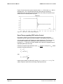
From control system theory two terms, “speed loop cutoff frequency” (Fcv ) and
“position loop cutoff frequency” (Fcp), are very useful for determining optimum
values of position loop gain and speed loop gain. The cutoff frequency is the
frequency at which the output amplitude is reduced by a factor of 2 (6 dB)
compared to the output amplitude at zero Hertz.
SAM Configuration Manual
P/n 9031 011 987, November 14, 2000
Page: 33
SAM CONFIGURATION MANUAL
SAM POSITION CONTROLLER - ITS TUNING
For a sinusoidal speed reference, at cutoff frequency (FCV):
speedreference
= speedlag
2
1
speed =
• acceleration
2π • FCV
speed =
acceleration =
speedlag • K d
J
Therefore:
FCV =
1 Kd
•
2π J
For the position loop with a double integral,
1
position =
2π • FCP
2
• acceleration
Therefore:
FCP =
The ratio
KP
1
•
2π
J
FCV
is called the damping ratio.
FCP
When the damping ratio is > 1 a system is referred to as over-damped, when the
damping ratio is < 1 a system is under-damped.
When the damping ratio = 1 the system is critically damped. A critically damped
system provides classically stable operation with optimum response (best
compromise for minimum overshoot with short settling time). In that case:
FCV = FCP
Then,
Kp
J
=
Kd
J
Therefore:
K
KP = d
J
2
This relationship is important because it shows that for constant damping, Kp is
proportional to
2
K d . This means that in order to maximize Kp (and therefore
minimize position lag) while maintaining stability, Kd must be made as large as
possible.
Page: 34
SAM Configuration Manual
P/n 9031 011 987, November 14, 2000
SAM CONFIGURATION MANUAL
SAM POSITION CONTROLLER - ITS TUNING
In practice, Kd is limited by several factors including the SAM Drive current loop
bandwidth which is directly related to the PWM frequency selected for the drive
(standard: 8 kHz; optional: 4 kHz). Other factors including resonance frequency of
the axis mechanics and signal to noise ratio of the speed measurement limit how
large Kd can be.
In practice Kd is increased to the point where the axis goes into sustained
oscillation, then reduced by a factor of 2 to obtain good speed loop stability. Kp is
K
then determined using the relationship K P = d
J
2
and fine tuned, if desired,
using a step response test.
PD Controller Performance verses Tuning
Figure 13 shows the response of a SAM Drive and AHR 142C6 motor to a step
torque disturbance equal to stall torque of the motor. In Figure 13, the Controller is
tuned for critically damped response (Fcp=Fcv=50Hz). Note that the motor
overshoots once by about 20% then settles to a steady state position lag of 1050
units (~ 5.8 degree).
Figure 13
PD Control - Critically Damped Response
Figure 14 shows the same system response with Fcv = 50 Hz and Fcp = 25 Hz
(damping ratio = 2, over-damped). Note that at this damping ratio there is no
overshoot; however, the settling time is longer and the steady state position lag is
four times greater due to the reduction in position loop gain.
Figure 14
SAM Configuration Manual
P/n 9031 011 987, November 14, 2000
PD Control - Over damped Response
Page: 35
SAM CONFIGURATION MANUAL
SAM POSITION CONTROLLER - ITS TUNING
Figure 15 shows the same system response when Fcv = 50 Hz and Fcp = 100 Hz
(damping ratio = 0.5, under-damped response). Note that the overshoot is
significantly larger and settling time has increased, but steady state position lag is
smaller due to increased position loop gain.
Figure 15
PD Control - Under damped Response
Some Theory regarding PID Position Control
PID control is similar to proportional plus derivative control but includes an
additional loop with a gain (Ki) and an integrator. This additional loop serves to
eliminate static position lags resulting from static disturbances. This loop can only
correct static disturbances or disturbances with frequencies below it’s cutoff
frequency (Fci). This loop is by itself unstable due to the three integrations and is
stabilized by the other two loops.
Unlike the proportional plus derivative case, Fci cannot be set equal to Fcp. Stable
operation is typically obtained at:
Fcv = Fcp
Fci = 0.63 • Fcp
with:
K I = 0.25 •
Kp
1.5
J
Higher system stability is achieved by setting Fcp<Fcv and Fci<0.63⋅Fcp. The
system response may be fine tuned using a step response test.
Page: 36
SAM Configuration Manual
P/n 9031 011 987, November 14, 2000
SAM CONFIGURATION MANUAL
SAM POSITION CONTROLLER - ITS TUNING
PID Controller Performance verses Tuning
Figure 16 shows the effect of adding integral control to a proportional plus
derivative control loop. In this illustration Fcp and Fcv are the same (50 Hz) as the
critically damped PD case (see Figure 13), and
Fci = 0.63 • Fcp = 32 Hz .
Note that the initial response (for the first 10 ms) is about the same as Figure 13,
but, as a result of the integral feedback, static position lag is reduced to zero.
Figure 16
PID Control - Critically Damped Response
In Figure 17, Fcv=Fcp=100Hz and Fci=63Hz. All three cutoff frequencies are
increased by 100% compared to Figure 16, resulting in a significant reduction of
position lag and settling time. Because the ratios of cutoff frequencies remain the
same, the general shape of Figure 16 is the same as Figure 17.
Figure 17
SAM Configuration Manual
P/n 9031 011 987, November 14, 2000
PID Control - Response with increased Cutoff Frequencies
Page: 37
SAM CONFIGURATION MANUAL
SAM POSITION CONTROLLER - ITS TUNING
Figure 18 shows the effect of reducing Fcp to 35 Hz. Fci is reduced to 20 Hz in
order to retain
Fci = 0.63 • Fcp . The reduction in Fci and Fcp increases stability
but slows the response.
Figure 18
PID Control – Over-damped Response
Figure 19 shows decreased stability when Fci is increased to 40 Hz, thus
increasing
Fci Fcp to 0.8, while keeping Fcp = Fcv = 50 Hz .
Figure 19
PID Control - Under-damped Response
In Figure 20, Fcp is reduced to 35 Hz with
Fci = 32 Hz and Fci Fcp = 0.91 .
The result once again is decreased stability.
Figure 20
Page: 38
PID Control - Under-damped Response
SAM Configuration Manual
P/n 9031 011 987, November 14, 2000
SAM CONFIGURATION MANUAL
SAM POSITION CONTROLLER - ITS TUNING
Some Theory regarding Feed-Forward Compensation
When a driven system and it’s behavior are well known, it is possible to create a
simplified mathematical model which takes into account the influences of
disturbances such as weight, static and viscous friction and the effect of load inertia
during acceleration/deceleration. With a degree of precision which increases the
closer the model comes to reality, the torque necessary for each movement may be
calculated and applied directly to the motor independent of any feedback. Due to its
“open-loop” nature, feed-forward compensation does not contribute to axis
instability and it is simple to setup. In many applications, utilization of feed-forward
compensation provides improved trajectory tracking accuracy using a less complex
Position Controller mode, with lower gains, improved stability, and no position
overshoot. The Position Controller remains active. It functions to compensate for
the remaining differences between the model and real system.
Figure 9 on page 26 shows SAM implementation of feed-forward compensation:
• For inertia compensation, a torque component proportional to acceleration is
created
• For viscous friction, a torque component proportional to speed is added
• For “dry friction”, a constant torque component with sign based on the speed
reference is summed into the composite torque command
• For weight, a torque component equal to a parameter setting is added
Benefits of using Feed-Forward – an example
Figure 21 shows the response of a critically damped proportional plus derivative
axis when commanded to move 1800 degrees (5 turns) at a velocity of 9000
2
degrees/sec. and an acceleration of 360,000 degrees/sec . The upper trace of
Figure 21 is the velocity profile of the move and the lower trace shows position lag.
Note that position lag increases significantly during the acceleration and
deceleration portions of the move due to the effects of the motor plus load inertia
which cannot be totally removed by the Controller’s position loop gain. During the
constant speed portion of the move, average position lag is approximately +50 due
to the static and viscous friction produced by the motor and load. The AC
component of position lag during the constant velocity portion of the move is due to
the inherent cyclical error of the resolver providing position and velocity feedback
for the axis.
Figure 21
SAM Configuration Manual
P/n 9031 011 987, November 14, 2000
PD Axis Response without Feed-forward Compensation
Page: 39
SAM CONFIGURATION MANUAL
SAM POSITION CONTROLLER - ITS TUNING
Figure 22 shows the same move with the Controller operating in PID mode and
adjusted for optimum response. The action of the integral feedback loop tends to
drive position lag toward zero during the intervals of constant acceleration and
constant speed; however, the peak to peak position lag is not reduced.
Figure 22
PID Axis Response without Feed-forward Compensation
Figure 23 shown the axis response to the same move following introduction of
feed-forward compensation in the Controller.
In this example, the Controller is configured as a proportional plus derivative
controller with the same proportional and derivative gain settings as for Figure 21.
Static friction, viscous friction and inertia compensation parameters, which were
previously zero, have been adjusted to the correct values for the motor and its load.
Due to the auto scaling feature of the SAM Tools Trace function, the position lag
appears larger than previous examples, but peak to peak position lag is now
approximately 110 (an 80% reduction) and average position lag is nearly zero.
Figure 23
Page: 40
PD Axis Respond with Feed-forward Compensation
SAM Configuration Manual
P/n 9031 011 987, November 14, 2000
SAM CONFIGURATION MANUAL
SAM POSITION CONTROLLER - ITS TUNING
Converting SAM Controller Parameters to “usual” units
Listed below are the SAM system-specific equations and relationships
corresponding to those listed in this general discussion of tuning principles.
M _ StallTorq
2π • 1000
M _ StallTorq
K P = R _ PGain •
4π
K D = R _ DGain •
8000
2π • 512
1
M _ StallTorq
• R _ DGain •
•
J
2π • 1000
M _ StallTorq 1
• R _ PGain •
•
J
4π
K I = R _ IGain • M _ StallTorq •
1
2π
1
Fcp =
2π
Fcv =
Fci =
1 3
M _ StallTorq
• R _ IGain •
• 1.35
2π
J
SAM Configuration Manual
P/n 9031 011 987, November 14, 2000
Page: 41
SAM CONFIGURATION MANUAL
SAM POSITION CONTROLLER - ITS TUNING
SAM Drive Tuning Procedure
Overview
This section presents step by step tuning procedures. Tuning parameters are
entered and adjusted using standard control panels provided with SAM Tools. Axis
responses are captured and displayed on a PC monitor using the SAM Tools traces
feature.
Preliminaries to Tuning
Prior to beginning any axis tuning procedure, the SAM Drive must be properly
configured with the correct motor parameters for the axis configuration. Any fault or
error conditions must be eliminated. A PC running SAM Tools and a SAM to
Service PC test/monitoring cable (ACC p/n 9032 010 689) are required to perform
the procedure.
To properly tune a SAM Drive the actual axis mechanical load should be connected
to the motor. In that case the system integrator must be very careful for not
ordering any motor movement that can be destructive or dangerous while tuning.
Load simulators (i.e. inertia wheels) are useful for preliminary setup, but are not
recommended when performing final controller adjustments because they seldom
duplicate the behavior of the actual axis load.
The axis load must be tightly coupled to the motor. Free-play or backlash between
the motor and load complicates the tuning process and prevents satisfactory
performance in most applications.
The optimum controller adjustment is not necessarily with all gain settings just
below the point of instability. A preferable strategy is to adjust the Controller to a
point where the desired performance is achieved with some additional margin.
The process of tuning may subject motors, SAM Drives and Dynamic Braking Resistors
to conditions exceeding the operating conditions encountered during execution of the
application for which the SAM system components were sized. SAM System
components are protected against overloads, but system integrators must be cognizant
of this possibility, and not operate the equipment outside its limits.
Motors may run faster or slower than expected, or in the opposite direction, or even go
into oscillations.
System integrators must take necessary precautions such as limiting maximum
torque to prevent erratic motor operation from harming personnel or the driven
equipment or the machine.
Page: 42
SAM Configuration Manual
P/n 9031 011 987, November 14, 2000
SAM CONFIGURATION MANUAL
SAM POSITION CONTROLLER - ITS TUNING
Select the Position Controller Operating Mode
The SAM Position Controller may be configured by parameter to operate in any of
the modes listed in Table 9, which also summarizes important performance
characteristics of each Controller mode. Select an operating mode based on the
axis configuration and performance required then tune the Controller using the
adjustment procedures for the operating mode selected.
Controller Mode
PD position control
PID position control
torque control
free
Table 9
Performance Characteristics
Classical PD (proportional plus derivative) control
loop. Average speed lag is zero. Static position lag is
proportional to disturbance torque.
Classical PID (proportional plus integral plus
derivative) control loop. Average speed lag is zero.
Static position lag in response to a disturbance torque
is zero.
Front end of Position Controller is disabled.
Application controls torque output directly.
Position Controller produces a rotating current vector.
This mode is used for motor wiring check.
Position Controller Modes
PD Controller Adjustment Procedure
This paragraph presents the step by step procedure for tuning any SAM Drive
whose Position Controller is to be configured to operate in PD or PID mode.
i
Step 1 through step 18 of this procedure are also used when adjusting a PID Controller
1)
Connect the Service PC running SAM Tools to the Service port of the SAM
Drive to be tuned.
2) Verify SAM Drive to Service PC communications by performing a handshake.
3) Setup the trace titled “TUNING.STC” (see Table 5, page 20). TUNING.STC is
found in the Promotion “CMDS” subdirectory.
SAM Configuration Manual
P/n 9031 011 987, November 14, 2000
Page: 43
SAM CONFIGURATION MANUAL
SAM POSITION CONTROLLER - ITS TUNING
4) Activate the control panel titled “TUNING.PAN”. TUNING.PAN is found in the
Promotion “PANELS” subdirectory.
SConf002.cdr
Figure 24
Tuning Control Panel with Least Significant digit of M_Stop0_AB Designated
5) On the TUNING control panel, record the current value of the least significant
digit of S_MStop0_AB (see Figure 24)
i
Do not forget to record the current value of S_MStop0_AB, as it will have to be
introduced again at the end of the tuning procedure.
6) Now change the least significant digit of S_MStop0_AB to “0”. This is
necessary to prevent position lag from causing a STOP 0 during tuning.
7) In the Ri_RegMode list entry box, select “REG_MODE_PDPOS”.
8) Set R_IGain, R_PGain, R_Inertia, R_StatFricTorq, and R_ViscFricTorq = 0.
9) If the required speed loop cutoff frequency (Fcv) and axis inertia (J) are known
a starting R_DGain setting may be calculated as follows:
4000 • π 2 • J • Fcv
R _ DGain =
, using the M_StallTorq value displayed on
M _ StallTorq
the control panel.
If not, set R_DGain = 10.
Page: 44
SAM Configuration Manual
P/n 9031 011 987, November 14, 2000
SAM CONFIGURATION MANUAL
SAM POSITION CONTROLLER - ITS TUNING
POWER ON
10) Press
. Verify that the SAM Drive status indicator displays [1]
continuously. If not, a fault/error condition exists which must be eliminated
before proceeding.
Before proceeding to next steps, make sure that the motor may move enough in both
directions without any danger neither for humans nor for the machine.
REL_MOVE
11) Click on
to produce a short movement of the axis motor. If the
motor goes into oscillation, or produces an unacceptable level of audible noise
before during or following the movement, reduce the R_DGain setting by 25%.
If there is no oscillation or unacceptable audio noise, increase the R_DGain
setting by 100%.
12) Repeat step 10 until the highest setting of R_DGain without oscillation or
unacceptable audible noise is found.
Be continuously aware that the motor is moving, and its load may thus hit machine
limits
13) Click on
POWER OFF
POWER ON
, then
to reset position lag to zero.
14) Calculate a starting value of R_PGain as follows:
R _ PGain = R _ DGain 2 •
M _ StallTorq 10 −6
•
,
π
J
where J is the axis total inertia. For M_StallTorq, use the value displayed on
the control panel.
If axis inertia is unknown, set R_PGain = R_DGain. If the axis goes into
oscillation, reduce R_PGain by 50%. If oscillation persists, reduce R_PGain by
increments of 50% until oscillation stops.
15) If the Trace Control panel (see Figure 6, page 22) is not visible on the monitor,
press
on the SAM Tools toolbar to bring in back into the foreground.
16) On the Trace Control panel press
START
to initiate a trace operation.
17) On the TUNING control panel, momentarily click and release
TORQUE STEP
UPLOAD
to inject a torque disturbance and trigger the trace. Press
on the
Trace Control panel when the button becomes active to upload the trace to the
monitor. The upload operation requires several seconds.
18) On the uploaded trace, note the general shape of POS_LAG at the positive
transition point of TORQ_FLOW. The objective is to find the best setting of
R_PGain for minimal overshoot and shortest settling time. Referring to the
waveforms in Figure 25, increase or decrease R_PGain and repeat steps 14
through 17 until a satisfactory critically damped response is obtained. Use large
increments of R-PGain (50% or so) initially until the upper and lower
boundaries of a critically damped response are found, then smaller increments
SAM Configuration Manual
P/n 9031 011 987, November 14, 2000
Page: 45
SAM CONFIGURATION MANUAL
SAM POSITION CONTROLLER - ITS TUNING
until the best overall R_PGain setting is obtained. The trace zoom feature may
be used to expand the area of interest.
i
SAM Tools automatically scale the vertical axis of each trace such that the display fills
the available space. When comparing data from successive traces, be sure to note also
the vertical axis scaling used.
On the uploaded traces, 180 units of POS_LAG represent approximately 1 degree of
position lag, as measured at the motor shaft.
Sconf003.cdr
Figure 25
i
Reference Waveforms for Proportional plus Derivative Tuning Step 17.
If adjusting the Controller for PID mode operation: Jump to step 1 of next section.
19) Set the Feed-forward compensation (see Feed-forward Compensation on page
49).
20) Restore original value of the least significant digit of S_MStop0_AB recorded in
step 5)
21) In the Ri_RegMode entry box, select “REG_MODE_PDPOS”.
STOP
Page: 46
Upon completion of this procedure, only the tuning parameters in RAM memory have
been revised. The tuning parameter values in flash memory remain unchanged.
Parameter values in RAM memory are lost upon power-down or resetting of the SAM
Drive.
To permanently save the tuning parameters (as well as all other parameters) in flash
memory, press the “SAVE PARAMETERS button on the Tuning control panel. To
create a file copy of the SAM Drive parameters see “Uploading Parameters” on page
14.
SAM Configuration Manual
P/n 9031 011 987, November 14, 2000
SAM CONFIGURATION MANUAL
SAM POSITION CONTROLLER - ITS TUNING
PID Controller Adjustment Procedure
This paragraph presents the step by step procedure for tuning any SAM Drive
whose Position Controller is to be configured to operate in PID (Proportional plus
Integral plus Derivative) mode.
i
Keep in mind that using the SAM Feed-forward compensation provides a better
accuracy than adding an integral part to the PD controller, when the goal is to follow a
“tricky” trajectory (i.e. pick-and-place, cam-profile) AND when load disturbances are
relatively small (i.e. 20% of motor rated torque).
The first part of this procedure is identical to the procedure for tuning a proportional
plus derivative axis.
1) Perform step 1 through step 18 of the “PD Controller Adjustment Procedure”
tuning procedure on page 43.
2) In the Ri_RegMode dialog box, select “REG_MODE_PIDPOS”.
3) If the axis inertia (J) is known a starting value of R_IGain may be calculated
using the following relationship:
R _ IGain =
4
1000 • π
• R _ PGain1.5 •
M _ StallTorq
J
For M_StallTorq, use the value displayed on the control panel.
If R_IGain cannot be calculated, set:
R _ IGain =
R _ PGain
3
4) If the Trace Control panel is not visible on the monitor, press
Tools toolbar to bring in back into the foreground. Press
trace operation.
on the SAM
START
5) On the Tuning Control Panel, momentarily click and release
to initiate a
TORQUE STEP
to
UPLOAD
on the
inject a torque disturbance and trigger the trace. Press
Trace Control window when the button becomes active to upload the trace to
the monitor.
SAM Configuration Manual
P/n 9031 011 987, November 14, 2000
Page: 47
SAM CONFIGURATION MANUAL
SAM POSITION CONTROLLER - ITS TUNING
6) On the uploaded trace, note the general shape of POS_LAG at the transition
points of TORQFLOW. The objective is to find the setting of R_IGain which
reduces POS_LAG to zero in the shortest time without increasing over-shoot.
Referring to the waveforms in Figure 26, increase or decrease R_IGain and
repeat steps 4 through 6 until a satisfactory critically damped response is
obtained. Use large increments of R_IGain (50% or so) initially until the upper
and lower boundaries of a critically damped response are found, then smaller
increments until the best overall R_IGain setting is found. The trace zoom
feature may be used to expand the area of interest.
Over-damped response
increase R_IGain
Critically damped response
R_IGain is fine
Under-damped response
decrease R_IGain
Sconf007.cdr
Figure 26
Example waveforms for Step 6.
7) Set the Feed-forward compensation (see Feed-forward Compensation on page
49).
8) Restore original value of the least significant digit of S_MStop0_AB recorded in
step 5 of the Proportional plus Derivative tuning procedure.
9) In the Ri_RegMode:Parameter Value list entry box, select
“REG_MODE_PIDPOS”.
STOP
Page: 48
Upon completion of this procedure, only the tuning parameters in RAM memory have
been revised. The tuning parameter values in flash memory remain unchanged.
Parameter values in RAM memory are lost upon power-down or resetting of the SAM
Drive.
To permanently save the tuning parameters (as well as all other parameters) in flash
memory, press the “SAVE PARAMETERS button on the Tuning control panel. To
create a file copy of the SAM Drive parameters see “Uploading Parameters” on page
14.
SAM Configuration Manual
P/n 9031 011 987, November 14, 2000
SAM CONFIGURATION MANUAL
SAM POSITION CONTROLLER - ITS TUNING
Feed-forward Compensation Adjustment Procedure
This procedure is applicable for PD and PID controller modes only. The “Torque”
and “Free” controller modes do not utilize feed-forward compensation. The general
sequence for setting feed-forward compensation values is weight, “dry friction”,
viscous friction then inertia.
1) Setup the trace titled “REGPOS.STC”, which is found in the Promotion “CMDS”
subdirectory.
2) On the Tuning control panel, note the current value of R_IGain. If R_IGain is
non-zero, record the value then temporarily set R_IGain = 0.
Adjusting the Weight compensation
3) If the axis weight (or constant force, i.e. produced by a spring) is known, enter
the value (in mNm) in the R_EXTTORQ numeric entry box.
If weight is unknown, read the value of field RF_TORQQUIET. As the motor is
stopped while the SAM power stage is on and the SAM PD (or PID) controller
has been previously tuned, the produced torque fits mainly to weight. Enter
then this value in the R_EXTTORQ numeric entry box
Adjusting the “Dry friction” compensation
4) If the axis static friction torque is known, enter the value (in mNm) in the
R_STATFRICTORQ numeric entry box. If static friction is unknown, enter zero.
5) Setup the control panel for a slow speed move (i.e. Travel_Speed = 360,
Acceleration & Deceleration = 3600, Rel_Move [deg] = 720).
6) On the Trace Control panel, press
START
to initiate a trace operation.
REL_MOVE
UPLOAD
to initiate an axis movement. Press
on the
7) Click on
Trace Control panel when the button becomes active to upload the trace to the
monitor.
8) On the uploaded trace, estimate by eye the average value of POSI_LAG. Adjust
R_STATFRICTORQ then repeat steps 6 and 7 until average POS_LAG is
approximately zero (See Figure 27). If POSI_LAG is > 0, increasing
R_STATFRICTORQ drives position lag in the negative (downward) direction.
Average position lag with no
R_VISCFRICTORQ compensation
Sconf008.cdr
Figure 27
SAM Configuration Manual
P/n 9031 011 987, November 14, 2000
With correct R_VISCFRICTORQ compensation,
average position lag during motion is ~0
(Watch the difference in vertical scales, as it
is automatically adjusted to the measure range)
Static friction compensation examples for step 8.
Page: 49
SAM CONFIGURATION MANUAL
SAM POSITION CONTROLLER - ITS TUNING
Adjusting the Viscous friction compensation
9) Setup the control panel for a medium speed move (i.e. Travel_Speed = 7200,
Acceleration & Deceleration = 36000, Rel_Move = 7200).
10) If the axis viscous friction torque is known, enter the value (in mNmS/100 Rad.)
as R_VISCFRICTORQ.
If viscous friction is unknown, enter zero.
11) On the Trace Control window, press
START
to initiate a trace operation.
REL_MOVE
UPLOAD
12) Click on
to initiate an axis movement. Press
on the
Trace Control window when the button becomes active to upload the trace to
the monitor.
13) On the uploaded trace, estimate by eye the average value of POSI_LAG during
the constant speed portion of the motion. Adjust R_VISCFRICTORQ then repeat
steps 11 and 12 until average POSITION LAG is approximately zero during the
constant speed portion of the movement. If POS_LAG is > 0, increasing
R_VISCFRICTORQ drives position lag in the negative (downward) direction.
Position lag with no R_VISCFRICTORQ compensation
Sconf009.cdr
Figure 28
With correct R_VISCFRICTORQ compensation,
average position lag during constant speed
is nearly 0.
(Watch the difference in vertical scales, as it
is automatically adjusted to the measure range.)
Viscous friction compensation examples for step 13
Adjusting the Inertia compensation
-6
2
14) If the axis inertia is known, enter the value (in 10 Km ) as R_INERTIA.
If inertia is unknown, enter zero. Set Rel_Move = 3600.
15) On the Trace Control window, press
Page: 50
START
to initiate a trace operation.
SAM Configuration Manual
P/n 9031 011 987, November 14, 2000
SAM CONFIGURATION MANUAL
SAM POSITION CONTROLLER - ITS TUNING
REL_MOVE
UPLOAD
16) Click on
to initiate an axis movement. Press
on the
Trace Control window when the button becomes active to upload the trace to
the monitor.
17) On the uploaded trace, estimate by eye the average value of POSI_LAG during
the acceleration and deceleration portions of the motion. Adjust R_INERTIA then
repeat steps 15 and 16 until POS_LAG is approximately zero during the
acceleration and deceleration portions of the movement. If POS_LAG is > 0,
increasing R_INERTIA drives position lag in the negative (downward) direction.
Position lag with no R_INERTIA compensation
Sconf010.cdr
Figure 29
With correct R_INERTIA compensation,
average position lag during constant speed
is nearly 0.
(Watch the difference in vertical scales, as it
is automatically adjusted to the measure range.)
Inertia compensation examples for Step 17
18) Repeating the whole procedure may enhance the precision of all feed-forward
compensation. Then use other Travel_Speed, Acceleration and Deceleration
settings, such as near the highest normal running speed, acceleration and
decelerations to be used in actual operation.
19) Restore the value of R_IGain recorded in step 2.
Torque Mode Adjustments
1) In the Ri_RegMode list entry box, select “REG_MODE_TORQUE”.
In this mode the Position Controller is totally inactive, and torque commands are
supplied by an external source.
Free Mode Adjustments
1) In the Ri_RegMode list entry box, select “REG_MODE_FREE”.
In this mode the Position Controller is totally inactive, and torque commands are
supplied by an external source.
SAM Configuration Manual
P/n 9031 011 987, November 14, 2000
Page: 51
SAM CONFIGURATION MANUAL
EMERGENCY STOP FUNCTIONS
Emergency STOP Functions
Overview
i
For additional information on "safe" drive functions and machine level safety and
protective functions, refer to the “PAM and SAM System User’s Handbook, Part 3 Safety and Protective Functions".
Error Response
Dedicated hardware in conjunction with extensive monitoring by the SAM Drive
firmware detect and respond to error/fault conditions occurring within the drive.
Four fault/error response levels are defined:
STOP 0
immediate deactivation of the drive Power Stage
STOP 1
controlled stop (constant deceleration ramp) followed by Power
Stage deactivation after a delay
STOP 2
controlled stop (as in STOP 1) but no Power Stage deactivation
USER SIGNAL
additional controlled stop (similar to STOP 2) for non error/fault
conditions (as defined by the application)
STOP 0, STOP 1, STOP 2 and USER SIGNAL conditions are treated as “events”
by PAM and SAM which means their occurrence initiates a defined response at the
application program level. They are represented in the SAM Status and produce an
indication on the Front Panel Status Indicator.
An application program can define how a SAM Drive responds to error/fault
conditions (i.e. STOP 0, STOP 1 or STOP 2 response). The responses to certain
critical fault/error conditions are defined by firmware (forced response) and not
user-alterable or maskable.
User Safety Inputs
On every SAM Drive discrete user safety inputs (USER STOP 0 and USER STOP 1) are
provided to permit a fault/error response to be initiated by external circuitry. USER
STOP 0 and USER STOP 1 are isolated 24 VDC PLC type user inputs. They provide
sufficient redundancy to satisfy the criteria for category III safe standstill (per
standard EN954-1).
Fatal Error Output
FATAL ERROR is a SAM Drive output (isolated relay contact) which is closed
whenever no fatal error condition exists, or when the internal voltage supplies are
not available. The FATAL ERROR contact normally controls current to a contactor
supplying AC power to the SAM system. Upon occurrence of a fatal error, the
FATAL ERROR contact opens, removing AC power from the SAM system.
Page: 52
SAM Configuration Manual
P/n 9031 011 987, November 14, 2000
CD HEX
STOP0
STOP1
STOP2
USER
Table 10
SAM Configuration Manual
P/n 9031 011 987, November 14, 2000
0x004B2583
0xF7800040 X X X X
0x00000020
0x00040000
X
X
X X
STATUS_C
STATUS_D
Motor parameters are not valid
Parametre write protected
Parametre given value out of range
Parametres value not accepted
Default value used for other parameters (warnin
Drives parameters are not valid
Stop 0 ordered
Stop 1 ordered
Stop 2 ordered
Out of position limits
Out of speed limits
Trace triggered (reserved for test purpose)
Ram Check error
Firmware corrupted
X X X X
X
X
X X
X
00
01
02
03
X X
04
05
06
07
X X X X X
08
Position lag greater than limit
High resolution resolver : measure defect
Low resolution resolver : measure defect
Encoder : measure defect
Magnetic angle not valid
Warning : High res. resolver meas. not good (nois
Brake option error
24 volt supply under warning limit
Aux sensor speed lag greather than limit
Motor thermal protection input active
Motor temperature greater than limit
Motor temperature > warning limit
Cooler temperature > warning limit
Ambient temperature greater than limit
Remote sensor error
STATUS_A
09
10
11
12
13
14
15
00
X X X X X X
Power stage OFF
No secondary CPU (DSP) acknowledge
X X
01
X
02
03
04
05
06
07
08
09
10
11
12
13
stop 0 input active
DC bus overvoltage
power transistor saturation fault
15 VDC supply low
DSP cycle duration beyond limit
DSP Ram Check error
MASK
junction over temperature
current regulator fault
0x59F9F401
0x000000DC
0x00000000
0x00000000
24 VDC low
STOP0
STOP1
STOP2
USER
14
AB HEX
Error reported
15
MASK
Host link transmission failure (hardware)
Host link disabled on corrupted frame
Host link disabled on time-out
Timeout waiting PAM synchronization
Host link communication RESET executed
Invalid host command data received
host cmd not executable due to the current state
Invalid host command code received
STOP1 input active
ref. speed not zero at power on
Option IO : outputs error
Option IO : 24 volt low
Stop0 on stop1 time-out
Application cycle duration beyond period
Main CPU cycle duration beyond limit
Main CPU fault (fault handler)
00
01
02
03
04
05
06
07
08
09
10
11
12
13
14
15
00
01
02
03
04
05
06
07
08
09
10
11
12
13
14
15
SAM CONFIGURATION MANUAL
EMERGENCY STOP FUNCTIONS
Brake Output Option
The Brake Option is used for controlling an electromechanical brake on a motor
equipped with this option. The output is on (conducting) when the power stage is
enabled; it is off (not conducting) when the power stage is disabled. As an
alternative the Brake Option can also be used for controlling a relay, which shortcircuits the motor for quick stopping.
Status and Display
For each SAM System software version, the detailed list of Front Display codes and
Status Bits is shown in ProMotion Help “SAM Status description” topic.
ProMotion Help “SAM Default action mask” topic shows the detailed default values
of all status masks. Table 10 shows this list as an example.
STATUS_B
X X X
X
X
X X
X
X
SAM Default action mask (valid only for System 2.0_2)
Page: 53
SAM CONFIGURATION MANUAL
EMERGENCY STOP FUNCTIONS
STOP 0
Activation
The STOP 0 error response (see Figure 30) can be activated by conditions internal
and external to the SAM Drive including:
• USER STOP 0 input is set to low state
• STOP0 command from the PAM or from SAM Tools (via the service port)
• STOP0 command from an application (sequence) running in the SAM Drive
• A status condition pre-defined by Drive firmware (STOP0 Forced Mask) to
initiate a STOP 0 becomes true
• A status condition pre-defined by the application (STOP0 Action Mask) to
initiate a STOP 0 becomes true
User
Stop0
Input
STOP0 Forced Mask
64
A08
64
Stop0
Cmd
Status
ABCD
D07
STOP0 User Mask
64
64
Q
D
62 (all except User
Stop 0 input and
Stop 0 command)
64
64
1
Reset
1
SAS018_D.CDR
Latched STOP0
(first Stop0 cause
latched for
diagnosis)
Figure 30
Page: 54
Fatal Error
Stop0
actions
STOP0 Activation
SAM Configuration Manual
P/n 9031 011 987, November 14, 2000
SAM CONFIGURATION MANUAL
EMERGENCY STOP FUNCTIONS
Execution
STOP0 causes the following actions (see Figure 31) within the affected axis:
• output transistors of power stage are disabled, removing drive current to the
axis motor
• Brake Control (Option) turns off current flow to motor brake
• The STOP0 EXECUTED status bit in SAM Drive Main Status is set
• Speed reference (internal TMP) is decreased to zero
• The STOP2 EXECUTED status bit in SAM Drive Main Status is set
• If the STOP 0 was activated internally by the SAM Drive firmware due to an
error condition, the FATAL ERROR contact opens
STOP
A STOP0 due to activation of the USER STOP 0 input or a STOP0 command from the
PAM or SAM Tools or from an internal sequence does not open the FATAL ERROR
contact.
Stop0
ON
Power
Stage
OFF
Ki_TmpStopDecel
Speed Ref
Brake
Output
Fatal
Error
On
Off
open
closed
STOP0
Executed
1
STOP2
Executed
1
Figure 31
SAM Configuration Manual
P/n 9031 011 987, November 14, 2000
Fatal Error does not open if STOP0
is due to an external activation
0
0
SAS022_A.CDR
STOP0 Execution
Page: 55
SAM CONFIGURATION MANUAL
EMERGENCY STOP FUNCTIONS
STOP 1
Activation
A STOP1 error response (see Figure 32) can be activated by conditions internal
and external to the SAM Drive including:
• USER STOP 1 input is set to low state
• STOP1 command from the PAM or from SAM Tools (via the service port)
• A status condition pre-defined by Drive firmware (STOP1 Forced Mask) to
initiate a STOP1 becomes true
• A status condition pre-defined by the application (STOP1 Action Mask) to
initiate a STOP1 becomes true
• STOP1 command from an application (Sequence) running in the SAM Drive
User
Stop1
Input
STOP1 Forced Mask
64
C07
64
Stop1
Cmd
Status
ABCD
D06
STOP1 User Mask
64
64
Q
D
62 (all except User
Stop1 input and
Stop1 command)
64
64
1
Reset
1
SAS020_B.CDR
Latched STOP1
(first Stop1 cause
latched for
diagnosis)
Figure 32
Page: 56
Delay
Stop1
actions
Fatal Error
STOP1 Activation
SAM Configuration Manual
P/n 9031 011 987, November 14, 2000
SAM CONFIGURATION MANUAL
EMERGENCY STOP FUNCTIONS
Execution
STOP1 causes the following actions (See Figure 33) within the affected axis:
• Immediate Controlled Stop (axis decelerates to zero speed at a specified rate)
• The STOP1 EXECUTED status bit in SAM Main Status is set
• The STOP2 EXECUTED status bit in SAM Main Status is set
The following actions are taken following execution of the controlled stop:
• Output transistors of power stage are disabled, removing drive current to the
axis motor
• Brake Control (Option) turns off current flow to motor brake
• If the STOP 1 was activated internally by the SAM Drive, the FATAL ERROR
contact opens
STOP
A STOP1 due to activation of the USER STOP 1 Input or a STOP1 command from the
PAM or SAM Tools or from an internal sequence does not open the FATAL ERROR
contact.
Stop1
Power
Stop1
ON
ON
OFF
OFF
Ki_TmpStopDecel
max: K_Stop1Timeout
(default: 1 second)
K_Stop1Timeout (default: 1 second)
Fatal
Error
unlocked
unlocked
locked
open
closed
Mi_BrakeLockDelay
Fatal Error opens,
except if STOP1 is due
to an external activation
locked
open
closed
STOP0
Executed
1
1
0
0
STOP1
Executed
1
1
0
0
STOP2
Executed
1
1
0
0
Normal case:
Deceleration + Delay < Timeout
Figure 33
SAM Configuration Manual
P/n 9031 011 987, November 14, 2000
Reaching timeout is
a STOP0 condition
Ki_TmpStopDecel
K_Stop1Delay
Speed Ref
Brake
Stop0
SAS023_B.CDR
Error case:
Deceleration + Delay > Timeout
STOP1 Execution
Page: 57
SAM CONFIGURATION MANUAL
EMERGENCY STOP FUNCTIONS
STOP2
Activation
The STOP2 error response is similar to STOP1 except the Power Stage is not
disabled and there is no external user input. STOP2 (see Figure 34) can be
activated in the following ways:
• STOP2 command from the PAM or from SAM Tools (via the service port)
• A status condition pre-defined by Drive firmware (STOP2 Forced Mask) to
initiate a STOP2 becomes true
• A status condition pre-defined by the application (STOP2 Action Mask) to
initiate a STOP2 becomes true
• STOP2 command from an application (Sequence) running in the SAM Drive
Stop2
Cmd
STOP2 Forced Mask
64
64
ABCD
Status
64
D05
STOP2 Action Mask
64
64
Q
D
64
Latched STOP2
1
SAS021_B.CDR
Stop2
Figure 34
Page: 58
STOP2 Activation
SAM Configuration Manual
P/n 9031 011 987, November 14, 2000
SAM CONFIGURATION MANUAL
EMERGENCY STOP FUNCTIONS
Execution
STOP2 causes the following actions (see Figure 35) within the affected axis
• Axis decelerates to zero speed at a specified rate
• The STOP2 EXECUTED status bit in SAM Main Status is set
STOP2 does not affect the Power Stage, Brake Control or FATAL ERROR contact.
Stop2
Power
Stage
ON
OFF
Ki_TmpStopDecel
Speed Ref
Brake
Output
Fatal
Error
On
Off
open
closed
STOP2
Executed
Figure 35
SAM Configuration Manual
P/n 9031 011 987, November 14, 2000
1
0
SAS024_B.CDR
STOP2 Execution
Page: 59
SAM CONFIGURATION MANUAL
EMERGENCY STOP FUNCTIONS
USER SIGNAL
Activation
The USER SIGNAL error response is similar to STOP2 except that it does not
influence directly the SAM Drive operation. It is used only for signaling to PAM
(and/or to an internal sequence) that a faulty condition occurred, such as a motor
temperature beyond “warning limit”, so that the machine can be slowed-down, or
stopped in a controlled way. USER SIGNAL (see Figure 36) can be activated in the
following ways:
• A status condition pre-defined by the application (USER SIGNAL Action Mask)
to initiate a USER SIGNAL becomes true
User Signal Action Mask
64
ABCD
Status
64
64
Q
D
64
Latched USER SIGNAL
1
USER SIGNAL
Figure 36
Sas025_c.cdr
USER SIGNAL Activation
Execution
USER SIGNAL causes the following actions within the affected axis:
• The USER SIGNAL status bit in SAM Main Status is set
User Signal
User
Si
l
Figure 37
STOP
Page: 60
1
0
Sas026 b cdr
STOP2 Execution
A USER SIGNAL does not open the FATAL ERROR contact.
SAM Configuration Manual
P/n 9031 011 987, November 14, 2000
SAM CONFIGURATION MANUAL
EMERGENCY STOP FUNCTIONS
Fatal Error
FATAL ERROR is a SAM Drive output (isolated relay contact set) which is closed
indicating no fatal error exists whenever all of the following conditions are satisfied:
• All internal supply voltages are okay (the DC Bus voltage is not considered an
internal supply voltage)
• Initialization and internal checking sequences have been successfully
completed
• Neither a STOP0 nor STOP1 internal error response has opened the FATAL
ERROR relay
The FATAL ERROR output opens immediately upon occurrence of any of the
following events:
• Any internal voltage supply fails
• An internal SAM Drive STOP0 or STOP1 error response opens the FATAL
ERROR contact
SAM Brake Option
Description
The SAM Brake Option is available on all SAM-DA-400-xxB-xxx-xxx. Only the
lowest current rated SAM-DA-400-07N-xxx-xxx are not fitted with this option.
This Option is fitted with a solid-state output, which reacts to short-circuit, and also
to open circuit (i.e. a brake wire gets broken). Such errors are signalized as "Brake
error”.
24VDC Ext
Undervoltage
Brake
Driver
Brake1
Brake2
Current
Limitation
Open Load
Detection
Short-Circuit
Detection
Diagnostic
_SBRA
SAH033_b.CDR
•
GND Ext
Figure 38
SAM Configuration Manual
P/n 9031 011 987, November 14, 2000
Brake Option Functional Diagram
Page: 61
SAM CONFIGURATION MANUAL
EMERGENCY STOP FUNCTIONS
Brake handling (brake enabled)
Automatic handling
At power on the brake is unlocked when the power stage is acknowledged ON.
At power off and STOP0 the brake is simultaneously locked when the power stage
is turned off (see section “STOP 0” on page 54).
During STOP1 execution, the brake is locked a few milliseconds before power off
action. The delay is corresponding to the value of the field LOCK_DELAY, default
value is 40 ms. In case of STOP1 time-out (occurring while speed does not fall
quickly enough to zero) turn off of power stage and brake lock are applied
simultaneously (see section “STOP 1” on page 56).
Manual handling
Lock and unlock method available from panel, when using SAM Tools.
Brake Object (class Cbrake)
Name
ENABLED
LOCK_STATE
LOCK_DELAY
Table 11
Type
BOOL
BOOL
UNS16
Access
RW
RO
RW
Units
ms
Description
option situation
ordered state of the brake
delay before locking used
by STOP1
Brake Object fields
Refer to ProMotion Help “SAM Parameters and Fields access” Topic, and select
“Brake fields for host”.
The field ENABLED is initialised to TRUE if:
• Ai_BrakeOptionInstalled = TRUE
AND
• Mi_BrakeEnabled = TRUE
The field is modified from the PAM application according to the ENABLED value of
the PAM brake declaration. Modification by panel is also possible.
Methods:
• lock
• unlock
lock of the brake (output is deactivated)
unlock of the brake (output is activated)
Parameters related to Brake Option
Name
Ai_BrakeOptionInstalled
Type
UNS16
Mi_BrakeLockDelay
UNS16
ms
Mi_BrakeEnabled
BOOL
ms
Table 12
Page: 62
Units
Description
0 = option not installed
1 = option installed
used to initialize LOCK_DELAY
field
default = 40 ms
Indicate motor with brake
default = TRUE
Brake Object parameters
SAM Configuration Manual
P/n 9031 011 987, November 14, 2000
SAM CONFIGURATION MANUAL
EMERGENCY STOP FUNCTIONS
Refer to ProMotion Help “SAM Parameters and Fields" Topic, and select “System
and motor parameters” for host access.
Brake behavior related to ENABLED field
Hardware Option
availability
not installed
FALSE
not installed
TRUE
installed
FALSE
installed
TRUE
Table 13
ENABLED
Behavior
Error report disabled
brake_lock = FALSE (logically)
Brake error signaled
brak_lock follow order (logically)
Error report disabled
brake_lock = FALSE (logically)
Brake error signaled
brak_lock follow order (logically)
Brake Object behavior
Brake error
Bit 10 of status B indicates a brake error (refer to chapter “Status and Display” on
page 53).
When set, the brake error bit of status B indicates any of following error conditions:
• short-circuit
• open load condition
• brake output transistor over-temperature
When the brake is enabled, but no hardware option is available (SAM-DA-400-xxNxxx-xxx), the brake error bit is set. By default, when set, the brake error bit
generates a STOP0 (see chapter “STOP 0” on page 53).
SAM Configuration Manual
P/n 9031 011 987, November 14, 2000
Page: 63
SAM CONFIGURATION MANUAL
CHECKING SAM-TO-MOTOR WIRING
Checking SAM-to-Motor Wiring
Motor and Feedback Wiring Errors
Errors in the resolver feedback wiring and motor windings wiring between a motor
and SAM Drive may produce erratic motion. This procedure provides a systematic
method for isolating wiring errors between a Servomotor with standard single speed
resolver and a SAM Drive.
Of the 720 possible ways to make resolver feedback connections to a SAM Drive,
only one arrangement is correct. Of the remaining 719 incorrect configurations,
most produce a Resolver A Measurement Error ([2] &[C] on the SAM Status
indicator). A few incorrect resolver wiring configurations produce only erratic motion
and - in some cases - an Excess Position Lag error ([2] & [y] on the SAM Status
indicator). This procedure is for isolating the causes of erratic motion where no
Resolver A Measurement Error is indicated.
The situation with motor winding connections is similar. Only one of the six possible
arrangements is correct. The 5 incorrect wiring arrangements cause erratic motion
and - in some cases - an Excess Position Lag error ([2] & [y] on the SAM Status
indicator).
Incorrect motor or drive parameters can produce symptoms similar to those caused
by motor or feedback wiring errors. Prior to performing this procedure, verify that
the SAM Drive contains the correct motor and drive parameters (see {reference to
downloading motor and drive parameters}) for the axis configuration.
This procedure utilizes the Control Panel “{control panel name}” which is a standard
panel provided with SAM Tools.
Checking Procedure
When performing this procedure, the motor may run at any speed and in any direction.
Prior to performing this procedure take measures necessary to prevent risk of damage
to the driven equipment and injury to personnel.
The correct wiring is described in the “PAM and SAM System User’s Manual, Part 2
– System Design and Integration”. Refer to it whenever necessary.
Page: 64
SAM Configuration Manual
P/n 9031 011 987, November 14, 2000
SAM CONFIGURATION MANUAL
CHECKING SAM-TO-MOTOR WIRING
step
procedure
normal response/indication
In this procedure the motor shaft
1
must be rotated by hand and it
must turn freely. If necessary,
uncouple the load from the motor.
Connect SAM Drive on axis to be none
2
tested to service PC running
SAM Tools
Apply 24 VDC power to SAM
After initialization SAM Drive
3
Drive.
status indicator displays [0]
continuously
4
5
6
7
8
Activate the “resolver.pan” control
panel.
While manually turning the motor
shaft in the clockwise direction
(as viewed from in front of the
motor mounting surface, looking
toward the motor) and frequently
refreshing the control panel
display, monitor the value of
POS_RES.
corrective action
none
If SAM Drive status indicator
displays other than [0] or
displays [0] in sequence with
other characters, other fault/error
conditions exist which must be
removed before proceeding with
this procedure.
none
POS_RES increases as the
motor shaft is rotated. At some
point, POS-RES rolls over to a
negative number and increases
toward zero as the motor shaft is
rotated.
If POS_RES decreases with
clockwise rotation of the motor
shaft, a wiring error exists in the
connections between the motormounted resolver and connector
X24 on the SAM Drive. Verify
SAM Drive to resolver feedback
wiring and correct any wiring
errors or substitute a known
good feedback cable and motor
of the same type and model.
SAM status indicator displays [1] If SAM status indicator displays
On the control panel:
indicating power stage is
other than [1], other fault/error
• select Regulation Mode =
enabled. The motor shaft rotates conditions exist which must be
Reg_Mode_Free
to the closest position where it is removed before proceeding.
• Set PosReg:TORQ_FLOW = in alignment with the current
1000
vector.
• Set CurReg:FREE_FREQ =
0.
If SAM status indicator does not
indicate [0], press “Reset
STATUS” button. Press “Power
ON” button.
Goal is enabling SAM to produce
a constant current vector locked
on the angle CurReg:TETA.
Try turning the motor shaft by
Magnetic flux produced by motor If no resistance is felt, verify all
motor windings connections from
hand.
current from the SAM Drive
SAM Drive connector X12 to the
creates an electrical détente,
motor windings connections
which prevents the motor shaft
from turning freely. When rotated
a few degrees in either direction Verify that DC Bus voltage is
and released, motor shaft returns present at the SAM Drive.
to its original position.
On the control panel:
Motor shaft rotates slowly in the If motor shaft rotation is counterclockwise or the motion is erratic
• Set CurReg:FREE_FREQ = clockwise direction at constant
or there is no rotation, check for
speed:
10
loose, broken or crossed
• ~36 RPM for 4 pole motors
SAM produces a current vector
connections from SAM Drive to
• ~24 RPM for 6 pole motors
which rotates at a frequency of
motor windings connections
1.2 Hz (approximately)
• ~18 RPM for 8 pole motors
SAM Configuration Manual
P/n 9031 011 987, November 14, 2000
Page: 65
SAM CONFIGURATION MANUAL
CHECKING SAM-TO-MOTOR WIRING
step
procedure
normal response/indication
corrective action
Motor shaft rotation stops
9
On the control panel:
• Set CurReg:FREE_FREQ = 0
10
On the control panel:
Motor shaft rotates into stable
position in alignment with current
• Set CurReg:TETA = -16384
vector at constant angle
designated by CurReg:TETA.
On the control panel, refresh
POS_RES falls within one of the If POS_RES is outside one of
11
panel then read
ranges of values listed in Table
the ranges of values listed in
MainSensor:POS_RES.
15 for the motor type.
Table 15 by just a few degrees,
increase PosReg:TORQ_FLOW
to 2000. This provides additional
current to overcome motor
friction.
If after increasing the value of
TORQ_FLOW, POS_RES is still
outside one of the ranges listed
in Table 15, multiply the
deviation by the number of pole
pairs for the motor model (see
Table 15).
Then, if the result is close to 90
or 180, look for a wiring error in
the resolver feedback
interconnections. A result close
to 120 strongly suggests a wiring
error in the motor winding
interconnections. Verify SAM
Drive to motor interconnections
or isolate the error by systematic
substitution of known good
feedback cable, motor windings
cable and motor of the same
model and type.
12
Restore the SAM Drive to its
normal operating configuration by
removing 24 VDC power. Wait a
few seconds then re-apply power.
The SAM drive restores the
normal configuration saved in
flash memory during initialization
Table 14
Page: 66
Resolver Feedback and Motor Windings Wiring Verification Procedure
SAM Configuration Manual
P/n 9031 011 987, November 14, 2000
SAM CONFIGURATION MANUAL
CHECKING SAM-TO-MOTOR WIRING
Servomotor type
AHD55x4
AHD70x4
AHR92x4
AHR115x6
AHR142x6
ABMR190x6
AHD190x8
All BAUTZ Mxxx
types
Table 15
SAM Configuration Manual
P/n 9031 011 987, November 14, 2000
poles
pole pairs
4 poles
2 pole pairs
POS_RES range
(for Table 14, step 11)
0 ±1.0
±180 ±1.0
6 poles
3 pole pairs
0 ±1.0
+120 ±1.0
-120 +±1.0
0 ±1.0
+90 ±1.0
±180 ±1.0
-90 ±1.0
0 ±1.0
+120 ±1.0
-120 +±1.0
8 poles
4 pole pairs
6 poles
3 pole pairs
POS_RES Values for ACC AC Servomotors
Page: 67