1
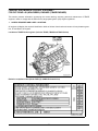
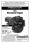
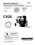
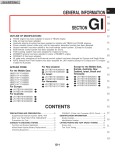
SM202T
SERVICE MANUAL
CX Forklift Truck
Federal Environmental Protection Agency (EPA) Emission-Control Compliant
S/N 130001A~
Gasoline and LP 800/1000CGL-8
800/1000CGB-8
800/1000PG(S/L)(2)-8
900PG(2)-8
1100PGA2-8
CX20
Diesel
WARNING
Read and observe all warnings on this unit
before operating it.
DO NOT operate this equipment unless all
factory-installed guards and shields are properly
secured in place.
ISSUED: MARCH 2006
800/900PD(2)-8
1000PD(S)(2)-8
1100PD(S)A2-8
INTRODUCTION
This Service Manual has been developed as an information resource to help the reader
learn about, understand, repair and maintain the CX20 Series forklift trucks, and the various equipment, systems, inspections, sensors, diagnostic procedures and diagnostic
equipment utilized to maintain, adjust and troubleshoot these systems. Although reference is made to maintenance procedures necessary to perform servicing of this vehicle,
you should refer to the applicable Operation and Maintenance Manual for these lift trucks
for more complete maintenance information.
TUSK is involved in a concentrated and highly technical program of designing and developing cleaner burning, more efficient and more powerful engines for use in the industrial
truck market. As a result, new computerized sensors, systems and diagnostic monitors
have been created to make the job of maintaining and repairing these systems simple
and easy.
Read this manual carefully, refer to it often and learn the repair, testing and adjustment
procedures to the best of your ability. Please note that some illustrations are generic and
may not look exactly like your unit in every detail.
Ensure that, when you are working on or around industrial trucks, Safety is priority
Number One. Read, understand and obey all WARNINGS and CAUTIONS.
Follow the instructions and procedures presented in this manual when working on these
lift trucks and their systems. Damage to the equipment, and possible injury to yourself or
others, may result if these procedures are not adhered to carefully.
Keep this manual nearby and accessible for use when necessary. If this book becomes
dirty, worn or illegible, contact TUSK for a replacement. The procedures outlined in this
manual will be updated periodically. Be sure that you have the latest revision in order to
learn the newest information available. Revision dates will be clearly displayed on the
lower left hand corner of the cover page.
This will aid in maintaining your equipment in excellent condition and in ensuring that
these lift trucks will operate safely at maximum efficiency.
3
ENGINE SERIAL NUMBER LOCATION
The TB45E series engine serial number is
stamped on a flat machined, painted pad on the
right side of the engine block just behind the distributor. The right side is determined by the operator’s right side when seated on the lift truck.
The serial number faces upwards for ease of identification.
The S6D102E series engine serial number is
stamped on the left side of the engine to the left of
the oil filter.
NOTICE
For EPA TB45E(D)(G)(L) engine-related troubleshooting,
refer to the following manual:
•
TM100 - “EPA Engine Training Manual”
NOTICE
For EPA S6D102E engine-related troubleshooting, refer
to the following manual:
•
SM140 - “S6D102E Service Manual”
4
CONTENTS
Page No.
INTRODUCTION . . . . . . . . . . . . . . . . . . . . . . . . . . . . . . . . . . . . . . . . . . . . . . . . . . . . . . . . . . . . . . . . . 3
ENGINE SERIAL NUMBER LOCATION . . . . . . . . . . . . . . . . . . . . . . . . . . . . . . . . . . . . . . . . . . . . . . . 4
FORKLIFT TRUCKS COVERED IN THIS PUBLICATION . . . . . . . . . . . . . . . . . . . . . . . . . . . . . . . . . 8
FEDERAL EPA EMISSION CONTROL STATEMENT . . . . . . . . . . . . . . . . . . . . . . . . . . . . . . . . . . . . 9
CH. 01 - SAFETY SECTION . . . . . . . . . . . . . . . . . . . . . . . . . . . . . . . . . . . . . . . . . . . . . . . . . . . . . . . . 1-1
SAFETY MANAGEMENT . . . . . . . . . . . . . . . . . . . . . . . . . . . . . . . . . . . . . . . . . . . . . . . . . . . . . . . . .1-2
SAFE TRAVEL . . . . . . . . . . . . . . . . . . . . . . . . . . . . . . . . . . . . . . . . . . . . . . . . . . . . . . . . . . . . . . . . .1-7
LOADING OPERATIONS . . . . . . . . . . . . . . . . . . . . . . . . . . . . . . . . . . . . . . . . . . . . . . . . . . . . . . . . .1-15
STOPPING AND PARKING . . . . . . . . . . . . . . . . . . . . . . . . . . . . . . . . . . . . . . . . . . . . . . . . . . . . . . .1-22
INSPECTION AND MAINTENANCE . . . . . . . . . . . . . . . . . . . . . . . . . . . . . . . . . . . . . . . . . . . . . . . .1-24
STRUCTURE AND STABILITY OF THE LIFT TRUCK . . . . . . . . . . . . . . . . . . . . . . . . . . . . . . . . . .1-32
SAFETY LABEL STICKING POSITIONS . . . . . . . . . . . . . . . . . . . . . . . . . . . . . . . . . . . . . . . . . . . . .1-35
CH. 02 - GENERAL INFORMATION AND SPECIFICATIONS . . . . . . . . . . . . . . . . . . . . . . . . . . . . . . 2-1
CH. 03 - SERVICE DATA . . . . . . . . . . . . . . . . . . . . . . . . . . . . . . . . . . . . . . . . . . . . . . . . . . . . . . . . . . 3-1
SERVICE DATA - GASOLINE ENGINE TRUCKS . . . . . . . . . . . . . . . . . . . . . . . . . . . . . . . . . . . . . .3-2
SERVICE DATA - DIESEL ENGINE TRUCKS . . . . . . . . . . . . . . . . . . . . . . . . . . . . . . . . . . . . . . . . .3-5
CH. 04 - TESTING, ADJUSTING AND MEASURING . . . . . . . . . . . . . . . . . . . . . . . . . . . . . . . . . . . . . 4-1
CHECKING ENGINE OIL (TB45E) . . . . . . . . . . . . . . . . . . . . . . . . . . . . . . . . . . . . . . . . . . . . . . . . . .4-2
ADJUSTING ENGINE OIL LEVEL . . . . . . . . . . . . . . . . . . . . . . . . . . . . . . . . . . . . . . . . . . . . . . . . . .4-2
ADJUSTING IGNITION TIMING (TB45E) . . . . . . . . . . . . . . . . . . . . . . . . . . . . . . . . . . . . . . . . . . . . .4-2
ADJUSTING SPARK PLUG GAP (TB45E) . . . . . . . . . . . . . . . . . . . . . . . . . . . . . . . . . . . . . . . . . . . .4-3
ADJUSTING VALVE CLEARANCE (TB45E) . . . . . . . . . . . . . . . . . . . . . . . . . . . . . . . . . . . . . . . . . .4-4
ADJUSTING VALVE CLEARANCE (S6D102E) . . . . . . . . . . . . . . . . . . . . . . . . . . . . . . . . . . . . . . . .4-5
ADJUSTMENT OF ENGINE DRIVE BELTS (TB45E) . . . . . . . . . . . . . . . . . . . . . . . . . . . . . . . . . . .4-7
MEASURING ENGINE CYLINDER COMPRESSION (TB45E) . . . . . . . . . . . . . . . . . . . . . . . . . . . .4-8
MEASURING HYDRAULIC DRIFT ON LIFT & TILT CYLINDERS . . . . . . . . . . . . . . . . . . . . . . . . .4-9
MAST . . . . . . . . . . . . . . . . . . . . . . . . . . . . . . . . . . . . . . . . . . . . . . . . . . . . . . . . . . . . . . . . . . . . . . . .4-10
ADJUSTING CLEARANCE - THRUST PAD AND RAIL . . . . . . . . . . . . . . . . . . . . . . . . . . . . . . . . . .4-12
ADJUSTING THE PARKING BRAKE LEVER . . . . . . . . . . . . . . . . . . . . . . . . . . . . . . . . . . . . . . . . .4-15
ADJUSTING THE ACCELERATOR PEDAL (TB45E ENGINE) . . . . . . . . . . . . . . . . . . . . . . . . . . . .4-15
ACCELERATOR PEDAL POSITION SENSOR - TB45 ENGINE . . . . . . . . . . . . . . . . . . . . . . . . . . .4-17
ADJUSTING ACCELERATOR PEDAL (S6D102E ENGINE) . . . . . . . . . . . . . . . . . . . . . . . . . . . . . .4-18
MEASURING BRAKE STOPPING DISTANCE (BRAKING EFFECT) . . . . . . . . . . . . . . . . . . . . . . .4-19
ADJUSTING THE INCHING/BRAKE PEDAL (TORQFLOW TRUCKS) . . . . . . . . . . . . . . . . . . . . .4-19
ADJUSTING THE STOP LAMP SWITCH . . . . . . . . . . . . . . . . . . . . . . . . . . . . . . . . . . . . . . . . . . . . .4-20
WHEEL BRAKE - ADJUSTING . . . . . . . . . . . . . . . . . . . . . . . . . . . . . . . . . . . . . . . . . . . . . . . . . . . .4-22
CHECKING TORQFLOW CLUTCH ACTUATION PRESSURE - PNEUMATIC TIRE . . . . . . . . . . .4-23
CHECKING TORQUE CONVERTER STALL SPEED . . . . . . . . . . . . . . . . . . . . . . . . . . . . . . . . . . .4-23
CHECKING TORQFLOW CLUTCH ACTUATION PRESSURE - CUSHION TIRE . . . . . . . . . . . . .4-24
CHECKING TORQUE CONVERTER STALL SPEED . . . . . . . . . . . . . . . . . . . . . . . . . . . . . . . . . . .4-24
INCHING VALVE/SPOOL ADJUSTMENT . . . . . . . . . . . . . . . . . . . . . . . . . . . . . . . . . . . . . . . . . . . .4-25
TESTING SPECIFIC GRAVITY OF BATTERY ELECTROLYTE . . . . . . . . . . . . . . . . . . . . . . . . . . .4-26
CHECKING TIRES AND ADJUSTING PNEUMATIC TIRE PRESSURE . . . . . . . . . . . . . . . . . . . . .4-27
MEASURING MINIMUM LEFT AND RIGHT TURNING RADIUS . . . . . . . . . . . . . . . . . . . . . . . . . .4-27
REAR AXLE - THRUST CLEARANCE ADJUSTMENT . . . . . . . . . . . . . . . . . . . . . . . . . . . . . . . . . .4-29
1
CH. 05 - INSPECTION . . . . . . . . . . . . . . . . . . . . . . . . . . . . . . . . . . . . . . . . . . . . . . . . . . . . . . . . . . . . . 5-1
INSPECT ENGINE STARTING OPERATION . . . . . . . . . . . . . . . . . . . . . . . . . . . . . . . . . . . . . . . . .5-2
INSPECT ENGINE RUNNING CONDITION . . . . . . . . . . . . . . . . . . . . . . . . . . . . . . . . . . . . . . . . . . .5-2
INSPECT AIR CLEANER ASSEMBLY . . . . . . . . . . . . . . . . . . . . . . . . . . . . . . . . . . . . . . . . . . . . . . .5-2
INSPECT/RETORQUE LOOSE CYLINDER HEAD MOUNTING BOLTS (TB45E) . . . . . . . . . . . .5-3
INSPECT ENGINE MOUNTS . . . . . . . . . . . . . . . . . . . . . . . . . . . . . . . . . . . . . . . . . . . . . . . . . . . . . .5-4
INSPECT THE ENGINE LUBRICATING SYSTEM . . . . . . . . . . . . . . . . . . . . . . . . . . . . . . . . . . . . .5-4
INSPECT ENGINE FUEL SYSTEM . . . . . . . . . . . . . . . . . . . . . . . . . . . . . . . . . . . . . . . . . . . . . . . . .5-5
INSPECT DIESEL FUEL INJECTION NOZZLES . . . . . . . . . . . . . . . . . . . . . . . . . . . . . . . . . . . . . . .5-5
INSPECT LPG VAPORIZER FOR TAR BUILDUP (EVERY MONTH) (TB45E) . . . . . . . . . . . . . . .5-6
INSPECT THE BLOW-BY GAS RECIRCULATION SYSTEM (TB45E) . . . . . . . . . . . . . . . . . . . . . .5-7
INSPECT COOLING SYSTEM AND RADIATOR . . . . . . . . . . . . . . . . . . . . . . . . . . . . . . . . . . . . . . .5-7
INSPECT COOLING WATER LEVEL . . . . . . . . . . . . . . . . . . . . . . . . . . . . . . . . . . . . . . . . . . . . . . . .5-8
INSPECT FAN ASSEMBLY . . . . . . . . . . . . . . . . . . . . . . . . . . . . . . . . . . . . . . . . . . . . . . . . . . . . . . .5-8
INSPECT CHARGING SYSTEM WIRING . . . . . . . . . . . . . . . . . . . . . . . . . . . . . . . . . . . . . . . . . . . .5-8
INSPECT FRONT AXLE AND RETORQUE MOUNTING BOLTS . . . . . . . . . . . . . . . . . . . . . . . . . .5-8
INSPECT REAR AXLE AND RETORQUE MOUNTING BOLTS . . . . . . . . . . . . . . . . . . . . . . . . . . .5-9
INSPECT WHEELS . . . . . . . . . . . . . . . . . . . . . . . . . . . . . . . . . . . . . . . . . . . . . . . . . . . . . . . . . . . . .5-9
INSPECT RIM SIDE RING . . . . . . . . . . . . . . . . . . . . . . . . . . . . . . . . . . . . . . . . . . . . . . . . . . . . . . . .5-9
INSPECT WHEEL BEARINGS . . . . . . . . . . . . . . . . . . . . . . . . . . . . . . . . . . . . . . . . . . . . . . . . . . . . .5-9
INSPECT STEERING KNUCKLES . . . . . . . . . . . . . . . . . . . . . . . . . . . . . . . . . . . . . . . . . . . . . . . . . .5-9
INSPECT STEERING WHEEL . . . . . . . . . . . . . . . . . . . . . . . . . . . . . . . . . . . . . . . . . . . . . . . . . . . . .5-10
INSPECT THE POWER STEERING SYSTEM . . . . . . . . . . . . . . . . . . . . . . . . . . . . . . . . . . . . . . . .5-10
INSPECT BRAKE SYSTEM RODS, CABLES AND LINKS . . . . . . . . . . . . . . . . . . . . . . . . . . . . . . .5-10
INSPECT BRAKE PIPING AND CONNECTIONS . . . . . . . . . . . . . . . . . . . . . . . . . . . . . . . . . . . . . .5-10
INSPECT BRAKE MASTER AND WHEEL CYLINDERS . . . . . . . . . . . . . . . . . . . . . . . . . . . . . . . . .5-11
INSPECT BRAKE SHOES AND ASSOCIATED PARTS . . . . . . . . . . . . . . . . . . . . . . . . . . . . . . . . .5-11
INSPECT BRAKE DRUMS . . . . . . . . . . . . . . . . . . . . . . . . . . . . . . . . . . . . . . . . . . . . . . . . . . . . . . . .5-11
INSPECT BRAKE BACKING PLATES . . . . . . . . . . . . . . . . . . . . . . . . . . . . . . . . . . . . . . . . . . . . . . .5-12
INSPECT LOAD FORKS . . . . . . . . . . . . . . . . . . . . . . . . . . . . . . . . . . . . . . . . . . . . . . . . . . . . . . . . .5-12
INSPECT MAST . . . . . . . . . . . . . . . . . . . . . . . . . . . . . . . . . . . . . . . . . . . . . . . . . . . . . . . . . . . . . . . .5-12
INSPECT FORK CARRIAGE . . . . . . . . . . . . . . . . . . . . . . . . . . . . . . . . . . . . . . . . . . . . . . . . . . . . . .5-13
INSPECT LIFT CHAINS . . . . . . . . . . . . . . . . . . . . . . . . . . . . . . . . . . . . . . . . . . . . . . . . . . . . . . . . . .5-13
INSPECT ATTACHMENTS . . . . . . . . . . . . . . . . . . . . . . . . . . . . . . . . . . . . . . . . . . . . . . . . . . . . . . . .5-13
INSPECT HYDRAULIC TANK . . . . . . . . . . . . . . . . . . . . . . . . . . . . . . . . . . . . . . . . . . . . . . . . . . . . .5-14
INSPECT CHASSIS AND ATTACHMENT PIPING . . . . . . . . . . . . . . . . . . . . . . . . . . . . . . . . . . . . .5-14
INSPECT HYDRAULIC PUMP . . . . . . . . . . . . . . . . . . . . . . . . . . . . . . . . . . . . . . . . . . . . . . . . . . . . .5-14
INSPECT LIFT CYLINDER . . . . . . . . . . . . . . . . . . . . . . . . . . . . . . . . . . . . . . . . . . . . . . . . . . . . . . . .5-14
INSPECT TILT CYLINDERS . . . . . . . . . . . . . . . . . . . . . . . . . . . . . . . . . . . . . . . . . . . . . . . . . . . . . . .5-14
INSPECT ATTACHMENT CYLINDERS (IF EQUIPPED) . . . . . . . . . . . . . . . . . . . . . . . . . . . . . . . . .5-14
INSPECT LIFT TRUCK CHASSIS AND FRAME . . . . . . . . . . . . . . . . . . . . . . . . . . . . . . . . . . . . . . .5-14
INSPECT CAB (IF EQUIPPED) . . . . . . . . . . . . . . . . . . . . . . . . . . . . . . . . . . . . . . . . . . . . . . . . . . . .5-14
INSPECT THE OPERATOR’S SEAT . . . . . . . . . . . . . . . . . . . . . . . . . . . . . . . . . . . . . . . . . . . . . . . .5-14
INSPECT EQUIPMENT USED FOR ACCESSING THE LIFT TRUCK . . . . . . . . . . . . . . . . . . . . . .5-14
INSPECT DISPLAY PANEL . . . . . . . . . . . . . . . . . . . . . . . . . . . . . . . . . . . . . . . . . . . . . . . . . . . . . . .5-15
INSPECT OVERHEAD GUARD . . . . . . . . . . . . . . . . . . . . . . . . . . . . . . . . . . . . . . . . . . . . . . . . . . . .5-15
INSPECT LIGHTS, GAUGES AND WARNING DEVICES . . . . . . . . . . . . . . . . . . . . . . . . . . . . . . . .5-15
INSPECT REAR VIEW MIRROR AND REFLECTORS . . . . . . . . . . . . . . . . . . . . . . . . . . . . . . . . . .5-15
CH. 06 - MAINTENANCE OPERATIONS . . . . . . . . . . . . . . . . . . . . . . . . . . . . . . . . . . . . . . . . . . . . . . 6-1
LUBRICANT LIST - GASOLINE ENGINE LIFT TRUCKS . . . . . . . . . . . . . . . . . . . . . . . . . . . . . . . .6-2
LUBRICANT LIST - DIESEL ENGINE LIFT TRUCKS . . . . . . . . . . . . . . . . . . . . . . . . . . . . . . . . . . .6-3
OIL AND GREASING CHART . . . . . . . . . . . . . . . . . . . . . . . . . . . . . . . . . . . . . . . . . . . . . . . . . . . . .6-8
CHANGING OIL AND FILTER IN GASOLINE ENGINES . . . . . . . . . . . . . . . . . . . . . . . . . . . . . . . .6-9
CHANGING OIL AND FILTER IN DIESEL ENGINES . . . . . . . . . . . . . . . . . . . . . . . . . . . . . . . . . . .6-11
2
CHANGING GEAR OIL IN DIFFERENTIAL CASE . . . . . . . . . . . . . . . . . . . . . . . . . . . . . . . . . . . . .6-12
CHANGING TRANSMISSION FLUID IN TORQFLOW TRANSMISSION CASE . . . . . . . . . . . . . . .6-13
CHANGING OIL IN HYDRAULIC TANK . . . . . . . . . . . . . . . . . . . . . . . . . . . . . . . . . . . . . . . . . . . . . .6-14
REPLACING THE FUEL FILTER - GASOLINE ENGINES . . . . . . . . . . . . . . . . . . . . . . . . . . . . . . .6-15
REPLACING THE FUEL FILTER - DIESEL ENGINES . . . . . . . . . . . . . . . . . . . . . . . . . . . . . . . . . .6-15
REPLACING AIR CLEANER ELEMENT - TB45E . . . . . . . . . . . . . . . . . . . . . . . . . . . . . . . . . . . . . .6-16
REPLACING AIR CLEANER ELEMENT - S6D102E . . . . . . . . . . . . . . . . . . . . . . . . . . . . . . . . . . . .6-17
CLEANING THE RADIATOR . . . . . . . . . . . . . . . . . . . . . . . . . . . . . . . . . . . . . . . . . . . . . . . . . . . . . .6-17
CLEANING RADIATOR FINS . . . . . . . . . . . . . . . . . . . . . . . . . . . . . . . . . . . . . . . . . . . . . . . . . . . . . .6-18
BLEEDING AIR FROM BRAKE SYSTEM . . . . . . . . . . . . . . . . . . . . . . . . . . . . . . . . . . . . . . . . . . . .6-18
CH. 07 - REMOVAL, DISASSEMBLY, ASSEMBLY, INSTALLATION . . . . . . . . . . . . . . . . . . . . . . . . 7-1
UNIT INSTALLATION POSITIONS DIAGRAM . . . . . . . . . . . . . . . . . . . . . . . . . . . . . . . . . . . . . . . .7-2
OVERALL DISASSEMBLY/ASSEMBLY FLOW CHART . . . . . . . . . . . . . . . . . . . . . . . . . . . . . . . . .7-3
WEIGHT TABLE - COMPONENT ASSEMBLIES AND PARTS . . . . . . . . . . . . . . . . . . . . . . . . . . . .7-4
MAST REMOVAL - TYPICAL . . . . . . . . . . . . . . . . . . . . . . . . . . . . . . . . . . . . . . . . . . . . . . . . . . . . . .7-5
ENGINE
ENGINE REMOVAL FROM CHASSIS . . . . . . . . . . . . . . . . . . . . . . . . . . . . . . . . . . . . . . . . . . . . . . .7-6
ENGINE DISASSEMBLY/ASSEMBLY . . . . . . . . . . . . . . . . . . . . . . . . . . . . . . . . . . . . . . . . . . . . . . .7-8
ENGINE INSTALLATION . . . . . . . . . . . . . . . . . . . . . . . . . . . . . . . . . . . . . . . . . . . . . . . . . . . . . . . . .7-8
TRANSMISSION AND DRIVE AXLE
TORQUE CONVERTER, TRANSMISSION, DRIVE AXLE REMOVAL FROM CHASSIS . . . . . . . .7-10
TORQUE CONVERTER INSTALLATION . . . . . . . . . . . . . . . . . . . . . . . . . . . . . . . . . . . . . . . . . . . .7-12
TRANSMISSION AND DRIVE AXLE INSTALLATION . . . . . . . . . . . . . . . . . . . . . . . . . . . . . . . . . . .7-12
PEDAL ASSEMBLY - BRAKE PIPING INSTALLATION . . . . . . . . . . . . . . . . . . . . . . . . . . . . . . . . .7-12
BRAKE SYSTEM - BLEEDING AIR FROM LINES . . . . . . . . . . . . . . . . . . . . . . . . . . . . . . . . . . . . .7-12
INSTALLING THE COUNTERWEIGHT . . . . . . . . . . . . . . . . . . . . . . . . . . . . . . . . . . . . . . . . . . . . . .7-13
MAST INSTALLATION - TYPICAL . . . . . . . . . . . . . . . . . . . . . . . . . . . . . . . . . . . . . . . . . . . . . . . . . .7-13
STEERING AXLE
STEERING AXLE AND POWER STEERING CYLINDER REMOVAL FROM CHASSIS . . . . . . . .7-14
POWER STEERING CYLINDER - STRUCTURE . . . . . . . . . . . . . . . . . . . . . . . . . . . . . . . . . . . . . .7-15
STEERING AXLE DISASSEMBLY . . . . . . . . . . . . . . . . . . . . . . . . . . . . . . . . . . . . . . . . . . . . . . . . . .7-16
STEERING AXLE - LUBRICATION AND TORQUE VALUES . . . . . . . . . . . . . . . . . . . . . . . . . . . . .7-17
STEERING AXLE - CHECKING SPECIFICATIONS . . . . . . . . . . . . . . . . . . . . . . . . . . . . . . . . . . . .7-18
STEERING AXLE AND POWER STEERING CYLINDER INSTALLATION . . . . . . . . . . . . . . . . . .7-19
STEERING AXLE TORQUE VALUES . . . . . . . . . . . . . . . . . . . . . . . . . . . . . . . . . . . . . . . . . . . . . . .7-20
WHEEL BRAKE
WHEEL BRAKE REMOVAL . . . . . . . . . . . . . . . . . . . . . . . . . . . . . . . . . . . . . . . . . . . . . . . . . . . . . . .7-22
WHEEL BRAKE - DISASSEMBLY/ASSEMBLY DRAWING - CUSHION . . . . . . . . . . . . . . . . . . . .7-23
WHEEL BRAKE - DISASSEMBLY/ASSEMBLY DRAWING - PNEUMATIC . . . . . . . . . . . . . . . . . .7-24
WHEEL BRAKE - STRUCTURE . . . . . . . . . . . . . . . . . . . . . . . . . . . . . . . . . . . . . . . . . . . . . . . . . . . .7-25
WHEEL BRAKE - INSTALLATION . . . . . . . . . . . . . . . . . . . . . . . . . . . . . . . . . . . . . . . . . . . . . . . . . .7-26
POWER STEERING VALVE (ORBITAL)
POWER STEERING VALVE - EXPLODED VIEW . . . . . . . . . . . . . . . . . . . . . . . . . . . . . . . . . . . . . .7-27
POWER STEERING VALVE - TROUBLESHOOTING CHART . . . . . . . . . . . . . . . . . . . . . . . . . . . .7-28
POWER STEERING VALVE - DISASSEMBLY . . . . . . . . . . . . . . . . . . . . . . . . . . . . . . . . . . . . . . . .7-30
POWER STEERING VALVE - CLEANING . . . . . . . . . . . . . . . . . . . . . . . . . . . . . . . . . . . . . . . . . . . .7-34
POWER STEERING VALVE - ASSEMBLY . . . . . . . . . . . . . . . . . . . . . . . . . . . . . . . . . . . . . . . . . . .7-34
POWER STEERING VALVE - INSTALLATION . . . . . . . . . . . . . . . . . . . . . . . . . . . . . . . . . . . . . . . .7-43
BRAKE BOOSTER AND MASTER CYLINDER
BRAKE MASTER CYLINDER - EXPLODED VIEW . . . . . . . . . . . . . . . . . . . . . . . . . . . . . . . . . . . . .7-44
BRAKE MASTER CYLINDER/BRAKE BOOSTER DIAGRAM . . . . . . . . . . . . . . . . . . . . . . . . . . . .7-46
3
BRAKE MASTER CYLINDER - DISASSEMBLY . . . . . . . . . . . . . . . . . . . . . . . . . . . . . . . . . . . . . . .7-47
BRAKE BOOSTER UNIT - DISASSEMBLY . . . . . . . . . . . . . . . . . . . . . . . . . . . . . . . . . . . . . . . . . . .7-48
BRAKE BOOSTER AND MASTER CYLINDER - SPECIFICATIONS . . . . . . . . . . . . . . . . . . . . . . .7-49
BRAKE BOOSTER AND MASTER CYLINDER - INSPECTION AND TESTING . . . . . . . . . . . . . .7-49
BRAKE MASTER CYLINDER - ASSEMBLY . . . . . . . . . . . . . . . . . . . . . . . . . . . . . . . . . . . . . . . . . .7-51
BRAKE BOOSTER - ASSEMBLY . . . . . . . . . . . . . . . . . . . . . . . . . . . . . . . . . . . . . . . . . . . . . . . . . . .7-51
POWER STEERING CYLINDER
POWER STEERING CYLINDER - DISASSEMBLY/ASSEMBLY - EXPLODED VIEW . . . . . . . . . .7-55
TILT CYLINDER
TILT CYLINDER - EXPLODED VIEW . . . . . . . . . . . . . . . . . . . . . . . . . . . . . . . . . . . . . . . . . . . . . . .7-56
TILT CYLINDER - DISASSEMBLY . . . . . . . . . . . . . . . . . . . . . . . . . . . . . . . . . . . . . . . . . . . . . . . . . .7-56
TILT CYLINDER - PARTS INSPECTION . . . . . . . . . . . . . . . . . . . . . . . . . . . . . . . . . . . . . . . . . . . . .7-57
TILT CYLINDER - REASSEMBLY . . . . . . . . . . . . . . . . . . . . . . . . . . . . . . . . . . . . . . . . . . . . . . . . . .7-57
DRIVE AXLE
DRIVE AXLE - DISASSEMBLY/ASSEMBLY - EXPLODED VIEW (PNEUMATIC) . . . . . . . . . . . . .7-59
DRIVE AXLE - ASSEMBLY - TORQUE CHART (PNEUMATIC) . . . . . . . . . . . . . . . . . . . . . . . . . . .7-60
DRIVE AXLE - DISASSEMBLY/ASSEMBLY - EXPLODED VIEW (CUSHION) . . . . . . . . . . . . . . .7-61
DRIVE AXLE - ASSEMBLY - TORQUE CHART (CUSHION) . . . . . . . . . . . . . . . . . . . . . . . . . . . . .7-62
DIFFERENTIAL
DIFFERENTIAL - TORQFLOW TRANSMISSION - DISASSEMBLY/ASSEMBLY
- EXPLODED VIEW . . . . . . . . . . . . . . . . . . . . . . . . . . . . . . . . . . . . . . . . . . . . . . . . . . . . . . . . . .7-63
DIFFERENTIAL - TORQFLOW TRANSMISSION - SPECIFICATIONS . . . . . . . . . . . . . . . . . . . . .7-64
DIFFERENTIAL- ADJUSTING . . . . . . . . . . . . . . . . . . . . . . . . . . . . . . . . . . . . . . . . . . . . . . . . . . . . .7-65
DIFFERENTIAL - ASSEMBLY . . . . . . . . . . . . . . . . . . . . . . . . . . . . . . . . . . . . . . . . . . . . . . . . . . . . .7-68
HYDRAULIC CONTROL VALVE
CONTROL VALVE - ASSEMBLY . . . . . . . . . . . . . . . . . . . . . . . . . . . . . . . . . . . . . . . . . . . . . . . . . . .7-69
CONTROL VALVE - WORK PORT RELIEF . . . . . . . . . . . . . . . . . . . . . . . . . . . . . . . . . . . . . . . . . . .7-70
SETTING PRESSURE ON WORK PORT RELIEF . . . . . . . . . . . . . . . . . . . . . . . . . . . . . . . . . . . . .7-70
TROUBLE SHOOTING THE ANTI-VOID FEATURE . . . . . . . . . . . . . . . . . . . . . . . . . . . . . . . . . . . .7-70
SERVICING AND REPAIR INFORMATION . . . . . . . . . . . . . . . . . . . . . . . . . . . . . . . . . . . . . . . . . . .7-70
SHUT-OFF VALVE . . . . . . . . . . . . . . . . . . . . . . . . . . . . . . . . . . . . . . . . . . . . . . . . . . . . . . . . . . . . . .7-71
SERVICE INFORMATION . . . . . . . . . . . . . . . . . . . . . . . . . . . . . . . . . . . . . . . . . . . . . . . . . . . . . . . .7-71
HYDRAULIC PUMP - GASOLINE ENGINES
HYDRAULIC PUMP - GASOLINE ENGINE (PNEUMATIC) . . . . . . . . . . . . . . . . . . . . . . . . . . . . . .7-73
HYDRAULIC PUMP - REAR PUMP SECTION - DISASSEMBLY- GASOLINE (PNEUMATIC) . . .7-74
HYDRAULIC PUMP - FRONT PUMP SECTION - DISASSEMBLY - GASOLINE (PNEUMATIC) .7-74
HYDRAULIC PUMP - REAR PUMP SECTION - REASSEMBLY - GASOLINE (PNEUMATIC) . . .7-74
HYDRAULIC PUMP - FRONT PUMP SECTION - REASSEMBLY - GASOLINE (PNEUMATIC) . .7-75
HYDRAULIC PUMP - GASOLINE ENGINE (CUSHION) . . . . . . . . . . . . . . . . . . . . . . . . . . . . . . . . .7-76
HYDRAULIC PUMP - REAR PUMP SECTION - DISASSEMBLY - GASOLINE (CUSHION) . . . . .7-77
HYDRAULIC PUMP - FRONT PUMP SECTION - DISASSEMBLY - GASOLINE (CUSHION) . . . .7-77
HYDRAULIC PUMP - REAR PUMP SECTION - REASSEMBLY - GASOLINE (CUSHION) . . . . .7-77
HYDRAULIC PUMP - FRONT PUMP SECTION - REASSEMBLY - GASOLINE (CUSHION) . . . .7-78
HYDRAULIC PUMP - INSPECTION AND REPAIR - GASOLINE (CUSHION) . . . . . . . . . . . . . . . .7-78
HYDRAULIC PUMP - DIESEL ENGINES
HYDRAULIC PUMP - FRONT UNIT - DIESEL . . . . . . . . . . . . . . . . . . . . . . . . . . . . . . . . . . . . . . . . .7-80
HYDRAULIC PUMP - FRONT PUMP UNIT - DISASSEMBLY - DIESEL . . . . . . . . . . . . . . . . . . . .7-80
HYDRAULIC PUMP - INSPECTION AND REPAIR PROCEDURES - DIESEL . . . . . . . . . . . . . . . .7-82
HYDRAULIC PUMP - REASSEMBLY OF FRONT PUMP UNIT - DIESEL . . . . . . . . . . . . . . . . . . .7-83
HYDRAULIC PUMP - OIL SEAL INSTALLATION JIG DIAGRAM . . . . . . . . . . . . . . . . . . . . . . . . . .7-85
HYDRAULIC PUMP - REAR UNIT - DIESEL - EXPLODED VIEW . . . . . . . . . . . . . . . . . . . . . . . . .7-86
HYDRAULIC PUMP - REAR PUMP UNIT - DISASSEMBLY - DIESEL . . . . . . . . . . . . . . . . . . . . . .7-87
4
HYDRAULIC PUMP - INSPECTION AND REPAIR PROCEDURES - DIESEL . . . . . . . . . . . . . . . .7-87
HYDRAULIC PUMP - REASSEMBLY OF REAR PUMP UNIT - DIESEL . . . . . . . . . . . . . . . . . . . .7-88
HYDRAULIC PUMP - TESTING . . . . . . . . . . . . . . . . . . . . . . . . . . . . . . . . . . . . . . . . . . . . . . . . . . . .7-91
HYDRAULIC PUMP - TROUBLESHOOTING . . . . . . . . . . . . . . . . . . . . . . . . . . . . . . . . . . . . . . . . .7-92
TORQFLOW TRANSMISSION - TORQUE CONVERTER - PNEUMATIC TRUCKS
TORQUE CONVERTER ASSEMBLY DRAWING . . . . . . . . . . . . . . . . . . . . . . . . . . . . . . . . . . . . . .7-93
TORQFLOW GEAR PUMP ASSEMBLY - EXPLODED VIEW (PNEUMATIC) . . . . . . . . . . . . . . . .7-94
TORQUE CONVERTER - PART SPECIFICATIONS (PNEUMATIC) . . . . . . . . . . . . . . . . . . . . . . .7-95
TORQUE CONVERTER - ASSEMBLY (PNEUMATIC) . . . . . . . . . . . . . . . . . . . . . . . . . . . . . . . . . .7-96
TORQUE CONVERTER - PRESSURE AND TORQUE SPECIFICATIONS
(PNEUMATIC) . . . . . . . . . . . . . . . . . . . . . . . . . . . . . . . . . . . . . . . . . . . . . . . . . . . . . . . . . . . . . .7-97
TORQUE CONVERTER/TRANSMISSION CONTROL VALVE - PNEUMATIC TRUCKS
OVERVIEW . . . . . . . . . . . . . . . . . . . . . . . . . . . . . . . . . . . . . . . . . . . . . . . . . . . . . . . . . . . . . . . . . . . .7-98
HANDLING PRECAUTIONS . . . . . . . . . . . . . . . . . . . . . . . . . . . . . . . . . . . . . . . . . . . . . . . . . . . . . .7-98
TORQUE CONVERTER ASSEMBLY . . . . . . . . . . . . . . . . . . . . . . . . . . . . . . . . . . . . . . . . . . . . . . . .7-98
CONTROL VALVE ASSEMBLY . . . . . . . . . . . . . . . . . . . . . . . . . . . . . . . . . . . . . . . . . . . . . . . . . . . .7-100
TORQUE CONVERTER ASSEMBLY - SECTIONAL VIEW (PNEUMATIC) . . . . . . . . . . . . . . . . . .7-101
TORQUE CONVERTER ASSEMBLY - ASSEMBLY DRAWING (PNEUMATIC) . . . . . . . . . . . . . .7-102
TORQUE CONVERTER ASSEMBLY - FLUID DIAGRAM (PNEUMATIC) . . . . . . . . . . . . . . . . . . .7-103
TORQUE CONVERTER - TROUBLESHOOTING CHART (PNEUMATIC) . . . . . . . . . . . . . . . . . . .7-104
TORQFLOW TRANSMISSION - PNEUMATIC TRUCKS
DISASSEMBLY . . . . . . . . . . . . . . . . . . . . . . . . . . . . . . . . . . . . . . . . . . . . . . . . . . . . . . . . . . . . . . . . .7-106
INPUT SHAFT - CLUTCH PACK DISASSEMBLY - EXPLODED VIEW . . . . . . . . . . . . . . . . . . . . .7-109
INTERMEDIATE SHAFT - DISASSEMBLY OF CLUTCH PACK - EXPLODED VIEW . . . . . . . . . .7-110
F1/R1 TRANSMISSION (SINGLE SPEED) - TESTING . . . . . . . . . . . . . . . . . . . . . . . . . . . . . . . . . .7-111
F1/R1 TRANSMISSION - SPECIFICATION TABLE . . . . . . . . . . . . . . . . . . . . . . . . . . . . . . . . . . . .7-112
F2/R1 TRANSMISSION (TWO SPEED) - TESTING . . . . . . . . . . . . . . . . . . . . . . . . . . . . . . . . . . . .7-114
F2/R1 TRANSMISSION - SPECIFICATION TABLE . . . . . . . . . . . . . . . . . . . . . . . . . . . . . . . . . . . .7-115
PRECAUTIONS ON ASSEMBLY . . . . . . . . . . . . . . . . . . . . . . . . . . . . . . . . . . . . . . . . . . . . . . . . . . .7-116
F1/R1 TRANSMISSION - INPUT SHAFT SUB-ASSEMBLY . . . . . . . . . . . . . . . . . . . . . . . . . . . . . .7-117
F1/R1 AND F2/R1 TRANSMISSIONS - INPUT SHAFT ASSEMBLY FLOWCHART . . . . . . . . . . .7-118
F2/R1 TRANSMISSION - INTERMEDIATE SHAFT SUB-ASSEMBLY . . . . . . . . . . . . . . . . . . . . . .7-120
F2/R1 TRANSMISSION - INTERMEDIATE SHAFT ASSEMBLY FLOWCHART . . . . . . . . . . . . . .7-121
OUTPUT SHAFT SUB-ASSEMBLY . . . . . . . . . . . . . . . . . . . . . . . . . . . . . . . . . . . . . . . . . . . . . . . . .7-122
OUTPUT SHAFT SUB-ASSEMBLY - ADJUSTING PINION SHAFT THRUST PROTRUSION . . .7-125
TRANSMISSION CASE - ASSEMBLY . . . . . . . . . . . . . . . . . . . . . . . . . . . . . . . . . . . . . . . . . . . . . . .7-126
F1/R1 TRANSMISSION - TORQFLOW TRANSMISSION ASSEMBLY DRAWING . . . . . . . . . . . .7-131
TRANSMISSION CONTROL VALVE - EXPLODED VIEW . . . . . . . . . . . . . . . . . . . . . . . . . . . . . . .7-132
TRANSMISSION CONTROL VALVE - SPECIFICATIONS . . . . . . . . . . . . . . . . . . . . . . . . . . . . . . .7-133
TRANSMISSION CONTROL VALVE - REMOVAL . . . . . . . . . . . . . . . . . . . . . . . . . . . . . . . . . . . . .7-135
TRANSMISSION CONTROL VALVE ASSEMBLY DRAWINGS . . . . . . . . . . . . . . . . . . . . . . . . . . .7-135
TRANSMISSION CONTROL VALVE - TROUBLESHOOTING . . . . . . . . . . . . . . . . . . . . . . . . . . . .7-140
TORQFLOW TRANSMISSION - TORQUE CONVERTER - CUSHION TRUCKS
TORQUE CONVERTER ASSEMBLY DRAWING . . . . . . . . . . . . . . . . . . . . . . . . . . . . . . . . . . . . . .7-141
TORQUE CONVERTER - PART SPECIFICATIONS (CUSHION) . . . . . . . . . . . . . . . . . . . . . . . . . .7-142
HYDRAULIC CIRCUIT DIAGRAM . . . . . . . . . . . . . . . . . . . . . . . . . . . . . . . . . . . . . . . . . . . . . . . . . .7-143
TORQUE CONVERTER PRESSURE TESTING PORTS (CUSHION) . . . . . . . . . . . . . . . . . . . . . .7-144
TORQUE CONVERTER TROUBLESHOOTING CHART (CUSHION) . . . . . . . . . . . . . . . . . . . . . .7-145
TORQFLOW TRANSMISSION - CUSHION TRUCKS
DISASSEMBLY . . . . . . . . . . . . . . . . . . . . . . . . . . . . . . . . . . . . . . . . . . . . . . . . . . . . . . . . . . . . . . . . .7-147
SERVICING AND INSPECTION . . . . . . . . . . . . . . . . . . . . . . . . . . . . . . . . . . . . . . . . . . . . . . . . . . . .7-153
5
FORKLIFT TRUCKS
COVERED IN THIS PUBLICATION
S/N 130001A~
MODEL
DESIGNATION
DESCRIPTION
ENGINE
GASOLINE AND LPG TRUCKS
800CG-8
8,000 lb. capacity, cushion tire truck, 1-speed transmission
TB45
800CGB-8
8,000 lb. capacity, cushion tire truck, Box Car Special (BCS), 1-spd. trans.
TB45
800PG-8
8,000 lb. capacity, pneumatic tire truck, compact wheelbase, 1-spd. trans.
TB45
800PG2-8
8,000 lb. capacity, pneumatic tire truck, compact wheelbase, 2-spd trans.
TB45
900PG-8
9,000 lb. capacity, pneumatic tire truck, long wheelbase, 1-spd. trans.
TB45
900PG2-8
9,000 lb. capacity, pneumatic tire truck,long wheelbase, 2-spd. trans.
TB45
1000PG-8
10,000 lb. capacity, pneumatic tire truck, long wheelbase, 1-spd. trans.
TB45
1000PG2-8
10,000 lb. capacity, pneumatic tire truck, long wheelbase, 2-spd. trans.
TB45
1000CG-8
10,000 lb. capacity, cushion tire truck, long wheelbase, 1-spd. trans.
TB45
1000CGB-8
10,000 lb. capacity, cushion tire truck, Box Car Special (BCS), 1-spd. trans.
TB45
1100PGA2-8
11,000 lb. capacity, pneumatic tire truck, long wheelbase, 2-spd. trans.
TB45
DIESEL TRUCKS
800PD-8
8,000 lb. capacity, pneumatic tire truck, compact wheelbase, 1-spd. trans.
S6D102E
800PD2-8
8,000 lb. capacity, pneumatic tire truck, compact wheelbase, 2-spd. trans.
S6D102E
900PD-8
9,000 lb. capacity, pneumatic tire truck, long wheelbase, 1-spd. trans.
S6D102E
900PD2-8
9,000 lb. capacity, pneumatic tire truck, long wheelbase, 2-spd. trans.
S6D102E
1000PD-8
10,000 lb. capacity, pneumatic tire truck, long wheelbase, 1-spd. trans.
S6D102E
1000PD2-8
10,000 lb. capacity, pneumatic tire truck, long wheelbase, 2-spd. trans.
S6D102E
1100PDA2-8
11,000 lb. capacity, pneumatic tire truck, long wheelbase, 2-spd. trans.
S6D102E
8
FEDERAL EPA EMISSION CONTROL STATEMENT
FOR OFF-ROAD LSI (NON-DIESEL) ENGINES (TB45E ENGINES)
This section presents information concerning the correct labeling, warranty, parts and maintenance of TB45E
engines in order to comply with the EPA off-road, large-spark-ignition (LSI) engine regulations.
1. LABELS REQUIRED AND LABEL LOCATIONS
All engines will display the required identification label as follows. Note that decal content will vary between gasoline, LP and Dual-Fuel engines.
Location on TB45E Series engines: (Includes TB45D, TB45G and TB45L Series)
Emission compliance label (DUAL-FUEL (D) SAMPLE shown below)
9
2. WARRANTY
The following statement is hereby provided as required by regulations of the United States Environmental Protection Agency (EPA).
YOUR WARRANTY RIGHTS AND OBLIGATIONS
All off-road large spark-ignition (LSI) engines must be designed, built and equipped to meet the Federal EPA’s
stringent anti-smog standards.
Tusk Lift Trucks (“TUSK”) must warrant the emission control system on your engine for the periods of time listed
below provided there has been no abuse, damage, neglect or improper maintenance of your engine.
Your emission control system may include parts such as the carburetor, regulator or fuel-injection system, ignition
system, engine computer unit (ECM), catalytic converter and air induction system.
Also included may be sensors, hoses, belts, connectors and other emission-related assemblies.
Where a warrantable condition exists, an Authorized Tusk Lift Trucks Dealer will repair your LSI engine at
no cost to you, including diagnosis, parts and labor.
MANUFACTURER’S WARRANTY COVERAGE
Beginning January 1, 2004 off-road large spark-ignition EPA engines are warranted for the time periods listed
below. If any emission-related part on your engine is defective, the part will be repaired or replaced by an Authorized Tusk Lift Trucks Dealer.
OWNER’S WARRANTY RESPONSIBILITIES
As the off-road LSI engine owner, you are responsible for the performance of the required maintenance listed in
your Operation and Maintenance Manual.
TUSK recommends that you retain receipts covering maintenance on your off-road engine, but TUSK cannot deny
warranty solely for the lack of receipts or for your failure to ensure the performance of all scheduled maintenance.
As the off-road large spark-ignition engine owner, you should be aware, however, that TUSK may deny you warranty coverage if your off-road large spark-ignition engine, or a part thereof, has failed due to abuse, damage,
neglect, improper maintenance or unapproved modifications.
Your engine is designed to operate on gasoline and/or LPG fuel. Use of any other fuel may result in your engine no
longer operating in compliance with the Federal EPA’s emissions requirements.
You are responsible for initiating the warranty process. It is suggested that you present your off-road large sparkignition engine to an Authorized TUSK Dealer as soon as you become aware that a problem exists. The warranty
repairs should be completed by the dealer as expeditiously as possible.
If you have any questions regarding your warranty rights and responsibilities, you should contact the TUSK Product Support Dept. at 1-770-385-4815.
In addition to the standard warranty periods, the components listed below are covered by the following specific
warranty periods.
10
EMISSION CONTROL WARRANTY – 36 MONTHS OR 2,500 HOURS FOR GENERAL PARTS
For the first 2,500 operating hours, or for a period of thirty-six months from the date of the first use by the original
purchaser from an Authorized Tusk Lift Trucks Dealer, whichever occurs first, TUSK warrants the following emission-related parts:
• Oxygen sensor
• PCV valve
• Water temperature
sensor
• Gasoline injector
• LPG injector
• LPG pressure sensor
• LPG solenoid
• LPG switching module
• Mass air flow sensor
• Throttle chamber
• Ignition coil
• Crankshaft position sensor
• Camshaft position sensor
• Distributor
• Spark plugs
EMISSION CONTROL WARRANTY – 36 MONTHS OR 4,000 HOURS FOR POWER TRAIN PARTS
• Intake manifold
• Exhaust manifold
EMISSION CONTROL WARRANTY – 60 MONTHS OR 3,500 HOURS FOR GENERAL PARTS
• ECM
• Catalytic converter
• Vaporizer
NOTICE
Follow the instructions in the Operations Manual concerning any other maintenance programs not
required for EPA compliance.
For questions and additional information concerning EPA Gasoline Engine Exhaust Regulations, contact:
Tusk Lift Trucks
14481 Lochridge Blvd., Bldg. #2
Covington, GA 30014-4908
Voice phone: (770) 385-4815
Fax phone: (770) 385-4838
11
FEDERAL EPA EMISSION CONTROL STATEMENT FOR
OFF-ROAD DIESEL ENGINES (S6D102E ENGINES)
Exhaust emissions produced by diesel engines are regulated by the United States Environmental Protection
Agency (EPA). This section presents information concerning the correct labeling, warranty, parts and maintenance
of S6D102E diesel engines in order to comply with current EPA regulations.
1. LABELS REQUIRED AND LABEL LOCATIONS
All certified S6D102E diesel engines will display the required identification labels (4) as follows:
• S6D102E diesel engines:
Labels will be affixed to all appropriate engines on TUSK production trucks.
Locations on S6D102E Series diesel engines:
1.1
EPA/EC CERTIFICATION DECAL (2 LOCATIONS) (SEE ITEM #1 IN PRECEEDING ILLUSTRATION)
1.2
EPA/EC CERTIFICATION ASSISTANCE PLATE (SEE ITEM #2 IN PRECEEDING ILLUSTRATION)
1.3
EPA/EC CERTIFICATION DATA PLATE (SEE ITEM #3 IN PRECEEDING ILLUSTRATION)
12
2. WARRANTY
The following statement is hereby provided as required by regulations of the United States Environmental Protection Agency (EPA).
YOUR WARRANTY RIGHTS AND OBLIGATIONS
The Federal EPA and Tusk Lift Trucks (hereinafter referred to as “TUSK”) are pleased to explain the emission control system warranty on your 2004 or later Diesel heavy duty off-road engine. All new, heavy-duty off-road engines
must be designed, built and equipped to meet the EPA’s stringent anti-smog standards. TUSK must warrant the
emission control system on your engine for the period of time listed below, provided there has been no abuse,
damage, neglect or improper maintenance of your engine.
Your emission control system may include parts such as fuel injection pump. Also included may be hoses, belts,
connectors and other emission-related assemblies.
Where a warrantable condition exists, an authorized TUSK dealer will repair the heavy-duty off-road engine at no
cost to the owner, including diagnosis, parts and labor.
Now, TUSK hereby certifies that diesel engines for lift trucks produced in 2004 model year and after shall be regulated by Federal EPA exhaust gaseous regulations. The difference between current and EPA-certified engines is
only the labels attached on the engine. See available drawing and/or illustration of emission label and its location.
13
MANUFACTURER’S WARRANTY COVERAGE
Beginning January 1, 2004 heavy-duty off-road EPA engines are warranted for a period of five (5) years, or threethousand (3,000) hours of operation, whichever occurs first. If any emission-related part on your engine is defective, the part will be repaired or replaced by at an authorized Tusk Lift Trucks dealer.
EMISSION-RELATED PARTS
• Fuel injection pump
• Fuel injection nozzles
• Turbocharger
OWNER’S WARRANTY RESPONSIBILITIES
As the heavy-duty off-road engine owner, you are responsible for the performance of the required maintenance
listed in owner's manual (Instruction Manual). TUSK recommends that you retain all receipts and records covering
the maintenance on your engine, but TUSK cannot deny warranty solely for the lack of receipts and records or for
your failure to ensure the performance of all scheduled maintenance. For your reference, the following is an emission control maintenance schedule for certified Diesel engines.
•
•
•
•
•
•
•
•
Check oil level and coolant level – Everyday
Change of lubricating – Every 200 hours
Change lubricating oil filter – Every 200 hours
Initial adjustment of valve clearance – Every 200 hours
Change fuel filter – Every 500 hours
Check turbocharger, rebuild or replace if necessary – Every 2,000 hours
Adjust valve clearance – Every 2,000 hours
Check fuel injection nozzles, replace if necessary – Every 2,000 hours
Keep records to show proof of compliance with the required maintenance practices and intervals.
• As the heavy-duty off-road engine owner you should, however, be aware that TUSK may deny your warranty coverage if your heavy-duty off-road engine or part has failed due to abuse, damage, neglect,
improper maintenance or disapproved modifications.
• Your engine is designed to operate on commercial diesel fuel only. Use of any other fuel in our engine
will result in the engine operating in non-compliance with the Federal EPA regulations.
You are responsible for initiating the warranty process. It is suggested that you present your heavy duty
off-road engine to an authorized TUSK dealer as soon as you become aware that problem exists. The
warranty repair should be completed by the dealer as expeditiously as possible.
• If you have any questions regarding your warranty rights and responsibilities, you should contact the
authorized TUSK dealer.
LIMITATIONS
TUSK is not responsible for resultant damages to an emission-related part or component resulting from:
•
•
•
•
Any application or installation TUSK deems improper as explained in the Instruction Manual.
Attachments, accessory items or parts not authorized for use by TUSK.
Improper off-road engine maintenance, repair or abuse.
Owner's unreasonable delay in making the product available after being notified of a potential product
problem.
This warranty is in addition to the TUSK standard warranty applicable to the off-road engine product involved.
Remedies under this warranty are limited to the provision of material and services as specified herein. TUSK is not
responsible for incidental or consequential damages, such as downtime or lost use of the forklift truck.
14
CUSTOMER ASSISTANCE – EMISSION CONTROL SYSTEMS WARRANTY
Tusk Lift Trucks aims to ensure that the Emission Control Systems Warranty is properly administered. In the event
that you do not receive the warranty service to which you believe you are entitled under the Emission Control Systems Warranty, call or write to your Tusk Lift Trucks Dealer.
Authorized dealers are recommended for major maintenance and repair work, as they are staffed with trained personnel, proper tools and are aware of the latest maintenance methods and procedures. Owners and others who
desire to perform their own work should purchase a service manual and obtain current service information from
their TUSK engine dealer.
NOTICE
Follow the instructions in the Operations Manual concerning any other maintenance programs not
required for EPA compliance.
For questions and additional information concerning EPA Diesel Engine Exhaust Regulations, contact:
Tusk Lift Trucks
14481 Lochridge Blvd., Bldg. #2
Covington, GA 30014-4908
Voice phone: (770) 385-4815
Fax phone: (770) 385-4838
15