1
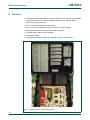
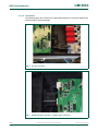
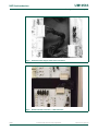
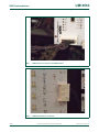
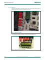
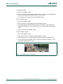
UM10563
Gaming suitcase demo system
Rev. 1 — 9 August 2012
User manual
Document information
Info
Content
Keywords
I2C-bus, I2C, PCU9669, bus controllers, LED driver, stepper motor,
Fast-mode Plus, Fm+, Ultra Fast-mode, UFm
Abstract
The ‘Gaming suitcase’ is a demonstration system for I2C-bus controllers,
LED drivers, and stepper motor controllers. This demo system enables
quick and easy evaluation of the PCU9669, PCU9655, PCU9955 and
PCA9629.
UM10563
NXP Semiconductors
Gaming suitcase demo system
Revision history
Rev
Date
Description
v.1
20120809
user manual; initial release
Contact information
For more information, please visit: http://www.nxp.com
For sales office addresses, please send an email to: [email protected]
UM10563
User manual
All information provided in this document is subject to legal disclaimers.
Rev. 1 — 9 August 2012
© NXP B.V. 2012. All rights reserved.
2 of 19
UM10563
NXP Semiconductors
Gaming suitcase demo system
1. Introduction
The ‘Gaming suitcase demo system’ is a demonstration kit for I2C-bus controllers, LED
drivers and stepper motors. This demonstration kit and software provide an overview of
the capabilities of its components and is easy to use.
The PCU9669 is a new generation I2C-bus controller that supports new ‘Ultra Fast-mode
(UFm)’ which is defined in latest I2C-bus specification (Ref. 1). The PCU9669 bridges
MCU’s parallel bus and 3 channel I2C buses (UFm × 2 channels + Fm+ × 1 channel). The
PCU9669 (and its family) has a large buffer to manage transfers with ultra low CPU load.
The PCU9955 is a constant current LED driver.
The PCU9655 is a voltage switch LED driver.
Sample code is available for the demo kit. The processor is an NXP LPC2214 ARM
microcontroller. The LPC12214 supports to build a feature-rich demo with its high
capability.
This evaluation board kit is populated with the following:
•
•
•
•
•
•
PCU9669 motherboard with ARM7 LPC2214 microcontroller
One 160-white-LED board (PCA9955)
Six 4-RGB-LED boards (PCU9655)
One 8-white-LED board (PCU9655)
Two 5-stepper motor boards (PCA9629)
Universal power supply
NXP gaming board block diagram
RGB LED
RGB LED
RGB LED
Top
160 WHITE LED
BOARD
six 8-pin
cables
RGB LED
RGB LED
WHITE LED
18-pin cable
PCU9655
DEMO BOARD
Address: 1100
14-pin
1-to-1 cable
PCU9955
DEMO BOARD
Address: 0100
14-pin LED (Rev) cable
14-pin 1-to-1 cable
Bottom
5-MOTOR
BOARD
5-MOTOR
BOARD
PCU9669
CONTROL BOARD
J13
power supply
J11
14-pin 1-to-1 cable
019aac715
(1) Channel 0 (J11) of PCU9669 is an Fm+ channel. Normal I2C-bus devices can be connected on this channel.
(2) Channel 1 (J12) and channel 2 (J13) of PCU9669 are UFm channels and are used for the Ultra-Fast mode LED controllers.
Fig 1.
Gaming suitcase block diagram
UM10563
User manual
All information provided in this document is subject to legal disclaimers.
Rev. 1 — 9 August 2012
© NXP B.V. 2012. All rights reserved.
3 of 19
UM10563
NXP Semiconductors
Gaming suitcase demo system
2. Features
• A complete demonstration platform for the PCU9669 I2C-bus controller, the PCU9655
and PCU9955 LED drivers, and the PCA9629 stepper motor controller used in
gaming and vending machines
•
•
•
•
•
•
Easy to use pre-programmed demonstrations
I2C connectors are compatible for I2C-bus slave device demo boards
Easy software development using Keil or GNU C compilers
Complete sample code for demo operation
Field programmable
Convenient test points for easy scope and logic analyzer measurements
019aac716
Fig 2.
UM10563
User manual
Gaming suitcase top and bottom panels
All information provided in this document is subject to legal disclaimers.
Rev. 1 — 9 August 2012
© NXP B.V. 2012. All rights reserved.
4 of 19
UM10563
NXP Semiconductors
Gaming suitcase demo system
3. Getting started
3.1 Assumptions
Familiarity with the I2C-bus is helpful but not required.
3.2 Target versions
This user manual is written based on the versions of:
• Sample code — version 1.0
3.3 Static handling requirements
CAUTION
This device is sensitive to ElectroStatic Discharge (ESD). Therefore care should be taken
during transport and handling. You must use a ground strap or touch the PC case or other
grounded source before unpacking or handling the hardware.
3.4 Ordering
Demo systems are available for loan to qualified users upon request at
[email protected].
3.5 Minimum requirements
3.5.1 Stand-alone demo
• A 100 V to 240 V AC power source
3.5.2 Development
•
•
•
•
•
UM10563
User manual
A 100 V to 240 V AC power source
USB cable with mini-USB connector
A PC with a C compiler such as Keil
PCU9669 motherboard
PCU9955, PCU9655 and PCA9629 demo boards
All information provided in this document is subject to legal disclaimers.
Rev. 1 — 9 August 2012
© NXP B.V. 2012. All rights reserved.
5 of 19
UM10563
NXP Semiconductors
Gaming suitcase demo system
3.6 Setup
This section describes how to set up the Gaming suitcase demo.
3.6.1 PCU9669 demo setup
3.6.1.1
Jumper settings
Default jumper and switch positions for the PCU9669 demo.
Table 1.
Jumper settings
Jumper
Position
Description
JP1
open (default)
reserved for microcontroller programming (CBUS1)
1-2
reserved
JP2
1-2
reserved for microcontroller programming (CPU Rst)
open (default)
reserved
JP3
open (default)
JTAG TRCK LPC2214 not returned
1-2
JTAG TRCK LPC2214 returned
JP5
open (default)
JTAG LPC2214 IDC +3.3 V power not connected
1-2
JTAG 2214 IDC +3.3 V power connected
JP11
open (default)
JTAG TCK PCA966x not returned
1-2
JTAG TCK 996x returned (pin 9 to 11)
JP12
open (default)
JTAG 996x IDC +3.3 V not connected
1-2
JTAG 996x IDC +3.3 V power connected
JP13
open
CH0 24 V power not connected
1-2 (default)
CH0 24V power connected
JP14
open (default)
CH0 test mode SCL0 pull-down disabled
1-2
CH0 test mode SCL0 pull-down enabled
JP15
open (default)
CH0 test mode SDA0 pull-down disabled
1-2
CH0 test mode SDA0 pull-down enabled
JP16
1-2 (default)
CH1 24 V power enabled
open
CH1 24 V power disabled
JP17
open (default)
CH1 test mode SCL1 pull-down disabled
1-2
CH1 test mode SCL1 pull-down enabled
JP18
open (default)
CH1 test mode SDA1 pull-down disabled
1-2
CH1 test mode SDA1 pull-down enabled
JP19
1-2 (default)
CH2 24 V power enabled
open
CH2 24 V power disabled
JP20
open (default)
CH2 test mode SCL2 pull-down disabled
1-2
CH2 test mode SCL2 pull-down enabled
JP21
open (default)
CH2 test mode SDA2 pull-down disabled
1-2
CH2 test mode SDA2 pull-down enabled
JP4
1-2
TXD - 2214 enabled
open (default)
TXD - 2214 disabled
Motherboard
UM10563
User manual
All information provided in this document is subject to legal disclaimers.
Rev. 1 — 9 August 2012
© NXP B.V. 2012. All rights reserved.
6 of 19
UM10563
NXP Semiconductors
Gaming suitcase demo system
Table 1.
Position
Description
JP7
1-2 (default)
LCD_D0 enabled
2-3
LCD_D0 disabled
JP8
1-2
LCD CMOS TX/RX disabled
2-3 (default)
LCD CMOS TX/RX enabled
JP9
open (default)
AIN0 pin 3/AIN1 pin 2/GND pin 1 headers — no jumpers
JP10
open (default)
LCD_D1 reserved
open (default)
LCD_D1 reserved
JP22
1-2 (default)
PCU9955 pwr pin 1 = 5 V selected
2-3
PCU9955 pwr pin 3 = 3.3 V selected
SV3
1-2 (default)
3.3 V Switched PS enabled
2-3
3.3 V Switched SV3 supply (banana plug)
SV4
1-2 (default)
3.3 V Master PS enabled
2-3
3.3 V Master SV4 supply (banana plug)
SV5
1-2 (default)
3.3 V PLL PS enabled
2-3
3.3 V PLL PS SV5 supply (banana plug)
SV6
1-2 (default)
5 V Switched enabled
2-3
5 V Switched SV6 supply (banana plug)
Table 2.
Position
Description
SW9
ON
S1: SCL0 pull-up
SW11
SW12
User manual
Switch positions
Switch
SW10
UM10563
Jumper settings …continued
Jumper
ON
S2: SDA0 pull-up
OFF
S3: SDA0 series resistor
OFF
S4: SCL0 series resistor
OFF
S1: SCL1 pull-up
OFF
S2: SDA1 pull-up
ON
S3: SDA1 series resistor
ON
S4: SCL1 series resistor
OFF
S1: SCL2 pull-up
OFF
S2: SDA2 pull-up
ON
S3: SDA2 series resistor
ON
S4: SCL2 series resistor
ON
S1: A0 PCU9955
ON
S2: A1 PCU9955
ON
S3: A2 PCU9955
ON
S4: A3 PCU9955
OFF
S5: RESET PCU9955
All information provided in this document is subject to legal disclaimers.
Rev. 1 — 9 August 2012
© NXP B.V. 2012. All rights reserved.
7 of 19
UM10563
NXP Semiconductors
Gaming suitcase demo system
Table 3.
160 white LED board
Jumper
Position
Description
J8, J16, J24, J32, J40, J48, 1-2 (default)
J56, J64, J72, J80, J88,
open
J96, J104, J112, J128,
J128
24 V power rail on pin 1
J7, J15, J23, J31, J39, J47, 1-2 (default)
J55, J63, J71, J79, J87,
J95, J103, J111, J119,
open
J127
Shorts four LEDs out of the string due to VLED limit
of 24 V.
J1 to J6, J9 to J14,
open (default)
J17 to J22, J25 to J30,
1-2
J33 to J38, J41 to J46,
J49 to J54, J57 to J62,
J65 to J70, J73 to J78,
J81 to J86, J89 to J94,
J97 to J102, J105 to J110,
J113 to J118, J121 to J126
Table 4.
Corresponding LED enabled.
Corresponding LED disabled.
PCU9955 demo board
Position
Description
J1
1-2 (default)
VLED 24 V
2-3
VLED 5 V
J4
J5
J6
J7
J8
J9
J10
User manual
String of four LEDs enabled.
Jumper
J3
UM10563
VLED power disabled.
1-2
PCU9955 PWR 3.3 V
2-3 (default)
PCU9955 PWR 5 V
1-2 (default)
A3 LOW (VSS)
2-3
A3 HIGH (VDD)
1-2 (default)
A2 LOW (VSS)
2-3
A2 HIGH (VDD)
1-2
A1 LOW (VSS)
2-3 (default)
A1 HIGH (VDD)
1-2 (default)
A0 LOW (VSS)
2-3
A0 HIGH (VDD)
open (default)
SCL pull-up disabled
1-2
SCL pull-up enabled
open (default)
SDA pull-up disabled
1-2
SDA pull-up enabled
1-2 (default)
Reset HIGH - inactive
open
Reset LOW - active
All information provided in this document is subject to legal disclaimers.
Rev. 1 — 9 August 2012
© NXP B.V. 2012. All rights reserved.
8 of 19
UM10563
NXP Semiconductors
Gaming suitcase demo system
Table 5.
Jumper
Position
J1
1-2
A0 LOW (VSS)
2-3 (default)
A0 HIGH (VDD)
1-2
PCU9655 PWR 3.3 V
2-3 (default)
PCU9655 PWR 5 V
1-2 (default)
A4 LOW (VSS)
2-3
A4 HIGH (VDD)
1-2 (default)
A3 LOW (VSS)
2-3
A3 HIGH (VDD)
1-2 (default)
A2 LOW (VSS)
2-3
A2 HIGH (VDD)
1-2
A1 LOW (VSS)
2-3 (default)
A1 HIGH (VDD)
J3
J4
J5
J6
J7
J8
J9
J10
JP9
User manual
Description
open
SCL pull-up disabled
1-2
SCL pull-up enabled
open
SDA pull-up disabled
1-2 (default)
SDA pull-up enabled
1-2 (default)
Reset HIGH - inactive
2-3
Reset LOW - active
1-2
VLED 5 V
2-3 (default)
VLED 24 V
Table 6.
Left stepper motor board
Jumper
Position
Description
J7
1-2 and 9-10
Address 40h
J11
1-2 and 15-16
Address 42h
J17
7-8 and 9-10
Address 44h
J23
7-8 and 15-16
Address 46h
J32
1-2 and 13-14
Address 48h
Table 7.
UM10563
PCU9655 demo board
Right stepper motor board
Jumper
Position
Description
J7
1-2 and 11-12
Address 4Ah
J11
7-8 and 13-14
Address 4Ch
J17
7-8 and 11-12
Address 4Eh
J23
5-6 and 9-10
Address 50h
J32
3-4 and 9-10
Address 52h
All information provided in this document is subject to legal disclaimers.
Rev. 1 — 9 August 2012
© NXP B.V. 2012. All rights reserved.
9 of 19
UM10563
NXP Semiconductors
Gaming suitcase demo system
3.6.1.2
Connections
The following figures are a collection of images that illustrate the connections between the
various boards in the demo system.
019aac717
Fig 3.
DC 24 V connector
019aac718
Fig 4.
UM10563
User manual
Board-to-board connection — stepper motor controllers
All information provided in this document is subject to legal disclaimers.
Rev. 1 — 9 August 2012
© NXP B.V. 2012. All rights reserved.
10 of 19
UM10563
NXP Semiconductors
Gaming suitcase demo system
019aac719
Fig 5.
Motherboard to stepper motor board connection
019aac720
Fig 6.
UM10563
User manual
Board-to-board connection — LED controllers
All information provided in this document is subject to legal disclaimers.
Rev. 1 — 9 August 2012
© NXP B.V. 2012. All rights reserved.
11 of 19
UM10563
NXP Semiconductors
Gaming suitcase demo system
019aac721
Fig 7.
LED160 18-pin connector on PCU9955 board
019aac722
Fig 8.
UM10563
User manual
LED160 board 18-pin connector
All information provided in this document is subject to legal disclaimers.
Rev. 1 — 9 August 2012
© NXP B.V. 2012. All rights reserved.
12 of 19
UM10563
NXP Semiconductors
Gaming suitcase demo system
019aac723
Fig 9.
RGB board connections
019aac724
Fig 10. PCU9669 socket
UM10563
User manual
All information provided in this document is subject to legal disclaimers.
Rev. 1 — 9 August 2012
© NXP B.V. 2012. All rights reserved.
13 of 19
UM10563
NXP Semiconductors
Gaming suitcase demo system
3.6.1.3
Power-on
Once the AC-DC adapter is connected to a mains outlet, a total of eight LEDs illuminate to
indicate the presence of power on the different power rails.
019aac725
Fig 11. LED power indicators
The LCD panel will display a message to indicate the demo is ready to run.
019aac726
Fig 12. LCD panel showing a ready status
UM10563
User manual
All information provided in this document is subject to legal disclaimers.
Rev. 1 — 9 August 2012
© NXP B.V. 2012. All rights reserved.
14 of 19
UM10563
NXP Semiconductors
Gaming suitcase demo system
To run the auto-demo:
1. Press ‘CPU_RESET’ button.
2. Press ‘F1’ button to run through automated routine. In this mode, all available LED
patterns and stepper motor patterns will run in a loop mode.
3. To end the demo, simply press the ‘CPU_RESET’ button.
To run in manual mode:
1. Press ‘CPU_RESET’ button.
2. Press ‘F2’ button to run through the first demonstration routine.
3. To cycle through the different demos, press the ‘F2’ button to move backwards
through the routines, or ‘F4’ to move forward. The ‘F3’ button lets the demo pattern
again.
4. To exit, press the ‘CPU_RESET’ button.
To check software revision:
1. Press ‘CPU_RESET’ button.
2. Press and hold ‘F3’ or ‘F4’ button to display software revision.
3. Press and hold ‘F3’ or ‘F4’ button again to display software build date and time.
4. To exit, press the ‘CPU_RESET’ button. (This is not necessary. Pressing F1 or F2
starts Auto or Manual demo mode.)
019aac727
Fig 13. CPU_RESET and F1 to F4 buttons
UM10563
User manual
All information provided in this document is subject to legal disclaimers.
Rev. 1 — 9 August 2012
© NXP B.V. 2012. All rights reserved.
15 of 19
UM10563
NXP Semiconductors
Gaming suitcase demo system
4. Troubleshooting
For issues not covered under this troubleshooting guide, please contact
[email protected].
Table 8.
UM10563
User manual
Troubleshooting guide
Problem
Solution
LCD displays ‘timeout’, nothing works.
PCU9669 socket might be loose. Assure good contact
on PCU9669, then press ‘CPU_RESET’ again. This
usually corrects the time-out issue and you can press F1
or F2 to start your routine.
Stepper motor boards will not start.
Press ‘CPU_RESET’ several times, then ‘F1’.
One or more motor board spinners
are not ‘in sync’ with other spinners.
Press ‘CPU_RESET’ and restart with ‘F1’.
Spinner not turning, strange sound
coming from motor board.
Spinner has been moved and is making contact with
optical switch. Move spinner by hand (soft metal), fix
bend or placement error until you can rotate by hand
through both sensors without touching.
Press ‘CPU_RESET’ and ‘F1’.
One or more spinners seem to have
incorrect timing, possibly one left motor
moving when right board is enabled
(as an example).
Address pins are incorrect. Verify address pin locations,
and restart demo.
Acting strange, not everything working.
Verify all eight red LEDs on the control board are lit up. If
not, possible power supply loss. Can be caused by
shorting connections on smaller boards or during ‘hot’
cable changes.
Parts damage seen on motor boards.
14-pin LED cable (which is wired reverse from standard
cable) has been plugged into motor boards. PCA9629’s
will be blown and need to be replaced as well as any
capacitors, inductors or ESD protection diodes before
boards will work correctly. Puts +24 V on +5 V line.
All information provided in this document is subject to legal disclaimers.
Rev. 1 — 9 August 2012
© NXP B.V. 2012. All rights reserved.
16 of 19
UM10563
NXP Semiconductors
Gaming suitcase demo system
5. Schematics
The following schematics are available from [email protected]:
• PCU9669 motherboard with ARM7 LPC2214 microcontroller motherboard:
PCU966x_V3_20.cct.pdf
• Stepper motor boards (PCA9629):
pca9629 5-motor design.pdf
• PCU9655 voltage switch LED controller board:
PCU9655_Daughter_card schematic.pdf
• PCU9955 constant current LED controller board:
PCU9955_daughter card schematic.pdf
• PCU9655 White LED daughter board:
PCU9655 WHITE LED Bar1 schematic.pdf
• PCU9655 RGB LED daughter board:
PCU9955 RGB LED BAR 1 schematic.pdf
• 160 White LED board:
PCU9955 White 160 LED board schematic.pdf
6. Abbreviations
Table 9.
Abbreviations
Acronym
Description
CPU
Central Processing Unit
ESD
ElectroStatic Discharge
Fm+
Fast-mode Plus
I2C-bus
Inter Integrated Circuit-bus
LCD
Liquid Crystal Display
LED
Light Emitting Diode
MCU
MicroController Unit
PC
Personal Computer
PLL
Phase-Locked Loop
RGB
Red/Green/Blue
SRAM
Static Random Access Memory
UFm
Ultra-Fast mode
USB
Universal Serial Bus
7. References
[1]
UM10563
User manual
UM10204, “I2C-bus specification and user manual” —
Rev. 4, 13 February 2012; NXP Semiconductors;
www.nxp.com/documents/user_manual/UM10204.pdf
All information provided in this document is subject to legal disclaimers.
Rev. 1 — 9 August 2012
© NXP B.V. 2012. All rights reserved.
17 of 19
UM10563
NXP Semiconductors
Gaming suitcase demo system
8. Legal information
8.1
Definitions
Draft — The document is a draft version only. The content is still under
internal review and subject to formal approval, which may result in
modifications or additions. NXP Semiconductors does not give any
representations or warranties as to the accuracy or completeness of
information included herein and shall have no liability for the consequences of
use of such information.
8.2
Disclaimers
Limited warranty and liability — Information in this document is believed to
be accurate and reliable. However, NXP Semiconductors does not give any
representations or warranties, expressed or implied, as to the accuracy or
completeness of such information and shall have no liability for the
consequences of use of such information. NXP Semiconductors takes no
responsibility for the content in this document if provided by an information
source outside of NXP Semiconductors.
In no event shall NXP Semiconductors be liable for any indirect, incidental,
punitive, special or consequential damages (including - without limitation - lost
profits, lost savings, business interruption, costs related to the removal or
replacement of any products or rework charges) whether or not such
damages are based on tort (including negligence), warranty, breach of
contract or any other legal theory.
Notwithstanding any damages that customer might incur for any reason
whatsoever, NXP Semiconductors’ aggregate and cumulative liability towards
customer for the products described herein shall be limited in accordance
with the Terms and conditions of commercial sale of NXP Semiconductors.
Right to make changes — NXP Semiconductors reserves the right to make
changes to information published in this document, including without
limitation specifications and product descriptions, at any time and without
notice. This document supersedes and replaces all information supplied prior
to the publication hereof.
Suitability for use — NXP Semiconductors products are not designed,
authorized or warranted to be suitable for use in life support, life-critical or
safety-critical systems or equipment, nor in applications where failure or
malfunction of an NXP Semiconductors product can reasonably be expected
to result in personal injury, death or severe property or environmental
damage. NXP Semiconductors and its suppliers accept no liability for
inclusion and/or use of NXP Semiconductors products in such equipment or
applications and therefore such inclusion and/or use is at the customer’s own
risk.
Applications — Applications that are described herein for any of these
products are for illustrative purposes only. NXP Semiconductors makes no
representation or warranty that such applications will be suitable for the
specified use without further testing or modification.
Customers are responsible for the design and operation of their applications
and products using NXP Semiconductors products, and NXP Semiconductors
accepts no liability for any assistance with applications or customer product
design. It is customer’s sole responsibility to determine whether the NXP
Semiconductors product is suitable and fit for the customer’s applications and
products planned, as well as for the planned application and use of
customer’s third party customer(s). Customers should provide appropriate
design and operating safeguards to minimize the risks associated with their
applications and products.
NXP Semiconductors does not accept any liability related to any default,
damage, costs or problem which is based on any weakness or default in the
customer’s applications or products, or the application or use by customer’s
UM10563
User manual
third party customer(s). Customer is responsible for doing all necessary
testing for the customer’s applications and products using NXP
Semiconductors products in order to avoid a default of the applications and
the products or of the application or use by customer’s third party
customer(s). NXP does not accept any liability in this respect.
Export control — This document as well as the item(s) described herein
may be subject to export control regulations. Export might require a prior
authorization from competent authorities.
Non-automotive qualified products — Unless this data sheet expressly
states that this specific NXP Semiconductors product is automotive qualified,
the product is not suitable for automotive use. It is neither qualified nor tested
in accordance with automotive testing or application requirements. NXP
Semiconductors accepts no liability for inclusion and/or use of
non-automotive qualified products in automotive equipment or applications.
In the event that customer uses the product for design-in and use in
automotive applications to automotive specifications and standards, customer
(a) shall use the product without NXP Semiconductors’ warranty of the
product for such automotive applications, use and specifications, and (b)
whenever customer uses the product for automotive applications beyond
NXP Semiconductors’ specifications such use shall be solely at customer’s
own risk, and (c) customer fully indemnifies NXP Semiconductors for any
liability, damages or failed product claims resulting from customer design and
use of the product for automotive applications beyond NXP Semiconductors’
standard warranty and NXP Semiconductors’ product specifications.
Evaluation products — This product is provided on an “as is” and “with all
faults” basis for evaluation purposes only. NXP Semiconductors, its affiliates
and their suppliers expressly disclaim all warranties, whether express, implied
or statutory, including but not limited to the implied warranties of
non-infringement, merchantability and fitness for a particular purpose. The
entire risk as to the quality, or arising out of the use or performance, of this
product remains with customer.
In no event shall NXP Semiconductors, its affiliates or their suppliers be liable
to customer for any special, indirect, consequential, punitive or incidental
damages (including without limitation damages for loss of business, business
interruption, loss of use, loss of data or information, and the like) arising out
the use of or inability to use the product, whether or not based on tort
(including negligence), strict liability, breach of contract, breach of warranty or
any other theory, even if advised of the possibility of such damages.
Notwithstanding any damages that customer might incur for any reason
whatsoever (including without limitation, all damages referenced above and
all direct or general damages), the entire liability of NXP Semiconductors, its
affiliates and their suppliers and customer’s exclusive remedy for all of the
foregoing shall be limited to actual damages incurred by customer based on
reasonable reliance up to the greater of the amount actually paid by customer
for the product or five dollars (US$5.00). The foregoing limitations, exclusions
and disclaimers shall apply to the maximum extent permitted by applicable
law, even if any remedy fails of its essential purpose.
Translations — A non-English (translated) version of a document is for
reference only. The English version shall prevail in case of any discrepancy
between the translated and English versions.
8.3
Trademarks
Notice: All referenced brands, product names, service names and trademarks
are the property of their respective owners.
I2C-bus — logo is a trademark of NXP B.V.
All information provided in this document is subject to legal disclaimers.
Rev. 1 — 9 August 2012
© NXP B.V. 2012. All rights reserved.
18 of 19
UM10563
NXP Semiconductors
Gaming suitcase demo system
9. Contents
1
2
3
3.1
3.2
3.3
3.4
3.5
3.5.1
3.5.2
3.6
3.6.1
3.6.1.1
3.6.1.2
3.6.1.3
4
5
6
7
8
8.1
8.2
8.3
9
Introduction . . . . . . . . . . . . . . . . . . . . . . . . . . . . 3
Features . . . . . . . . . . . . . . . . . . . . . . . . . . . . . . . 4
Getting started . . . . . . . . . . . . . . . . . . . . . . . . . . 5
Assumptions . . . . . . . . . . . . . . . . . . . . . . . . . . . 5
Target versions . . . . . . . . . . . . . . . . . . . . . . . . . 5
Static handling requirements . . . . . . . . . . . . . . 5
Ordering . . . . . . . . . . . . . . . . . . . . . . . . . . . . . . 5
Minimum requirements . . . . . . . . . . . . . . . . . . . 5
Stand-alone demo. . . . . . . . . . . . . . . . . . . . . . . 5
Development . . . . . . . . . . . . . . . . . . . . . . . . . . 5
Setup . . . . . . . . . . . . . . . . . . . . . . . . . . . . . . . . 6
PCU9669 demo setup . . . . . . . . . . . . . . . . . . . 6
Jumper settings . . . . . . . . . . . . . . . . . . . . . . . . 6
Connections . . . . . . . . . . . . . . . . . . . . . . . . . . 10
Power-on . . . . . . . . . . . . . . . . . . . . . . . . . . . . 14
Troubleshooting. . . . . . . . . . . . . . . . . . . . . . . . 16
Schematics . . . . . . . . . . . . . . . . . . . . . . . . . . . . 17
Abbreviations . . . . . . . . . . . . . . . . . . . . . . . . . . 17
References . . . . . . . . . . . . . . . . . . . . . . . . . . . . 17
Legal information. . . . . . . . . . . . . . . . . . . . . . . 18
Definitions . . . . . . . . . . . . . . . . . . . . . . . . . . . . 18
Disclaimers . . . . . . . . . . . . . . . . . . . . . . . . . . . 18
Trademarks. . . . . . . . . . . . . . . . . . . . . . . . . . . 18
Contents . . . . . . . . . . . . . . . . . . . . . . . . . . . . . . 19
Please be aware that important notices concerning this document and the product(s)
described herein, have been included in section ‘Legal information’.
© NXP B.V. 2012.
All rights reserved.
For more information, please visit: http://www.nxp.com
For sales office addresses, please send an email to: [email protected]
Date of release: 9 August 2012
Document identifier: UM10563