1
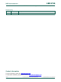
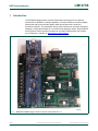
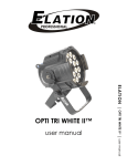
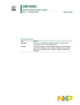
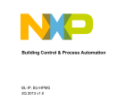
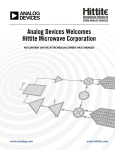
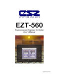
UM10798
PCA9629A advanced stepper motor controller demo kit
(OM13285)
Rev. 1 — 17 June 2014
User manual
Document information
Info
Content
Keywords
Fm+ I2C-bus, PCA9629A, GPO, LPCXpresso LPC1343 daughter card,
sensor, stepper motor, motor direction, speed and ramp control
Abstract
PCA9629A demo kit (OM13285) is designed to let customers evaluate the
PCA9629A in a realistic application. The demo kit includes a stepper
motor board with sensors and the stepper motor demo board with a
number of pre-defined functions. The functions are executed by pressing
push-button switches on the demo board.
UM10798
NXP Semiconductors
PCA9629A advanced stepper motor controller demo kit (OM13285)
Revision history
Rev
Date
Description
1.0
20140617
User manual; initial version
Contact information
For more information, please visit: http://www.nxp.com
For sales office addresses, please send an email to: [email protected]
UM10798
User manual
All information provided in this document is subject to legal disclaimers.
Rev. 1 — 17 June 2014
© NXP Semiconductors N.V. 2014. All rights reserved.
2 of 35
UM10798
NXP Semiconductors
PCA9629A advanced stepper motor controller demo kit (OM13285)
1. Introduction
The PCA9629A Stepper Motor Controller Demo Board is designed to let customers
evaluate the PCA9629A in a realistic application. The demo board kit includes a Stepper
Motor board with sensors and the Stepper Motor Demo Board with a number of
pre-defined functions. The parameters used by these functions can be easily changed by
changing a configuration header file. To customize the application further, the generalized
driver functions used in the demo firmware can be easily modified with a free compiler
tool, LPCXpresso, available at: www.lpcware.com/lpcxpresso.
Fig 1.
OM13285 PCA9629A stepper motor controller demo board Rev. 2.2
UM10798
User manual
All information provided in this document is subject to legal disclaimers.
Rev. 1 — 17 June 2014
© NXP Semiconductors N.V. 2014. All rights reserved.
3 of 35
UM10798
NXP Semiconductors
PCA9629A advanced stepper motor controller demo kit (OM13285)
1.1 Application overview
The PCA9629A Demo board is designed for easy setup and ease of operation. The demo
functions are executed by pressing a control button on the demo board. The PCA9629A
Demo functions supported by the demo board and firmware include:
Mode — This selects Full Step, Half Step, or Two-Phase drive.
Direction — This selects clockwise or counter-clockwise starting direction.
Rotate Fixed Steps — This rotates the motor a fixed number of steps or ramp-up and
ramp-down control function.
Rotate Fixed Rotations — This rotates the motor for a fixed number of rotations or ramp
up and down control function.
Rotate and Reverse — Rotates the motor for a fixed number of rotations, stops (wait a
delay time), reverses, and rotates the same fixed number of rotations in the other
direction.
Continuous Rotation — Continuously rotate the motor and the button is pressed again
to change speed with ramp control.
Interrupt mode — This starts the motor rotating in the ‘Interrupt Auto clear mode’ where it
starts one direction until the optical interrupter connected to the motor shaft passes
through one of the slotted optical switches. It then stops (wait a delay timer), and reverses
until an interrupter passes through the second slotted optical switch. This process
continues until the button is pressed again to stop.
Some of the other features of the PCA9629A demo board are:
•
•
•
•
•
•
•
Programmable I2C-bus address selection up to 16 slave devices
Optional either MOSFET with Schottky diode or Darlington sink driver
Access to all PCA9629A I/O, including the ability to isolate any or all device pins
Test point access to monitor many onboard signals
Flexibility to use external controller with onboard drive
Requires +12 V input, has onboard +5 V and +3.3 V regulators
Flexible reprogramming, firmware updating via several methods
– USB (X1)
– LPC-Link USB (J3 in LPCXpresso daughter board)
– RS-232 (X2)
2. PCA9629A stepper motor controller demo kit
2.1 PCA9629A demo kit (Rev. 2.2) contents
•
•
•
•
•
•
UM10798
User manual
PCA9629A demo board with LPC1343 LPCXpresso daughter board
+12 V DC power adapter
Stepper motor board with sensor
Motor cable (6-wire)
Sensor cable (4-wire)
Demo board quick start instructions
All information provided in this document is subject to legal disclaimers.
Rev. 1 — 17 June 2014
© NXP Semiconductors N.V. 2014. All rights reserved.
4 of 35
UM10798
NXP Semiconductors
PCA9629A advanced stepper motor controller demo kit (OM13285)
3. System overview
3.1 The PCA9629A stepper motor controller
Stepper motors can be driven and controlled in a number of different ways, depending on
the type of motor being driven and the application requirements for the motor. The most
basic form of drive is single-phase drive or ‘wave drive’. The other common drive modes
include 2-phase, 1⁄2-step, and micro-step. The main advantage of the 1⁄2-step or
micro-step mode is to break the steps into smaller increments to minimize resonance
effects that could be a problem in certain applications. Stepper motor can also be
designed for unipolar and/or bipolar drive. The PCA9629A is designed for single-phase,
2-phase, and 1⁄2-step operation. This application only deals with interface to a unipolar
motor.
The PCA9629A has an internal oscillator, so no external components are required. Some
of the other features of the PCA9629A include:
• Stand-alone operation: generates motor coil drive phase sequence signals for use
with an external high current driver to off-load master controller/micro
• Programmable step rate: 333.3 kpps to 0.3 pps with ±3 % accuracy
• Programmable number of steps and motor action either multiple times (1 to 255) or
continuously
• Sensor enabled drive control: linked to interrupt from P0 and P1 inputs with noise filter
enable or disable feature
•
•
•
•
Programmable four GPIO ports and four GPO ports
Programmable ramp-up from start and ramp-down to stop
Programmable re-enable ramp-up or ramp-down to change ramp rate curve on the fly
Programmable start, ramp-up/ramp-down, stop or reverse the direction either
clockwise or counter-clockwise of rotation control of stepper motor
• Programmable restart motor with new speed and operation while motor is still running
• Programmable loop delay timer for motor reversal mode
• Interrupt auto clear function linked extra steps, direction reversal and stop control
without microcontroller handling
• 32-bit step counter to count output steps
• Selectable active hold (last state), power on, power off, or released states for motor
shaft
• Four balanced push-pull type outputs capable of sinking 25 mA or sourcing 25 mA for
glueless connection to external high current drivers needed to drive motor coils
• Up to 1000 pF loads with 100 ns rise and fall times on outputs
UM10798
User manual
All information provided in this document is subject to legal disclaimers.
Rev. 1 — 17 June 2014
© NXP Semiconductors N.V. 2014. All rights reserved.
5 of 35
UM10798
NXP Semiconductors
PCA9629A advanced stepper motor controller demo kit (OM13285)
3.2 LPCXpressso microcontroller board
The LPCXpresso target board, jointly developed by NXP, Code Red Technologies, and
Embedded Artists (www.embeddedartists.com/products/lpcxpresso/), includes an
integrated JTAG debugger (LPC-Link), so there is no need for a separate JTAG debug
probe. The target and debugger can be easily cut apart, allowing them to be used
separately. The target portion of the board can connect to expansion boards to provide a
greater variety of interfaces, and I/O devices. The LPC-Link debugger provides a
high-speed USB to JTAG/SWD interface to the IDE. It can be connected to other debug
targets such as a customer prototype. For the PCA9629A demo board application, the
debugger portion (LPC-Link) can be cut off, but a connector is installed to allow
connection to the debugger if necessary. Two headers are also installed to mate the pin
connections on the LPCXpresso board to the PCA9629A main board connectors. The
onboard LPC1343 is then programmed with the firmware to support the demo application.
Code was developed for the application using the LPCXpresso IDE. This is based on the
popular Eclipse development platform and includes several LPC-specific enhancements.
It is an industry-standard GNU tool chain with an optimized C library that gives engineers
all the tools necessary to develop high-quality software solutions quickly and
cost-effectively. The C programming environment includes professional-level features.
There is syntax coloring, source formatting, function folding, online and offline help, and
extensive project management automation. If the user wants to customize the demo or
write their own application code, the code is free to download at the link above.
3.3 System block diagram
A block diagram of the PCA9629A demo system is shown in Figure 2.
+3.3 V POWER
+5 V POWER
+12 V POWER
Mini-USB
DEBUG
RS-232
LPCXpresso
LPC1343
I2C-bus
PCA9629A
Fm+ I2C-bus
STEPPER MOTOR
CONTROLLER
+
DRIVERS
STEPPER
MOTOR
MOTOR
SENSORS
Stepper Motor Board
SWITCHES
LEDs
WINI2C-USB
aaa-013575
Fig 2.
UM10798
User manual
PCA9629A demo board system block diagram
All information provided in this document is subject to legal disclaimers.
Rev. 1 — 17 June 2014
© NXP Semiconductors N.V. 2014. All rights reserved.
6 of 35
UM10798
NXP Semiconductors
PCA9629A advanced stepper motor controller demo kit (OM13285)
3.4 I/O, switches and indicators on the PCA9629A demo board
The interface connections, switches and indicators on the PCA9629A demo board are
shown in Figure 3.
Fig 3.
PCA9629A demo board interfaces, switches and indicators
UM10798
User manual
All information provided in this document is subject to legal disclaimers.
Rev. 1 — 17 June 2014
© NXP Semiconductors N.V. 2014. All rights reserved.
7 of 35
UM10798
NXP Semiconductors
PCA9629A advanced stepper motor controller demo kit (OM13285)
3.4.1 Sensor interface
The sensor interface allows connection to slotted optical switches and bias components
mounted on the Stepper motor board being connected to the PCA9629A. The sensors are
utilized in Interrupt mode to demonstrate the interrupt autoclear capabilities of the
PCA9629A. The interrupt autoclear capability allows one sensor to clear the interrupt
caused by the other sensor. This action can result in stopping the motor, reversing the
motor, or adding extra steps or rotations before stopping or reversing the motor.
3.4.2 Motor interface
The motor interface provides power as well as the phased outputs from either the bipolar
Darlington driver or the MOSFET drivers. The PCA9629A coil driver outputs,
OUT0 to OUT3, are connected to the inputs of the bipolar or MOSFET driver via
selectable jumper block (JP14).
3.4.3 RS-232 programming interface
An RS-232 interface is provided as a method of programming and updating firmware on
the LPC1343 microcontroller (Ref. 3). The details and required utilities to update the
firmware are discussed in the programming section, Section 7.3 of this manual.
3.4.4 USB programming interface
A Full Speed USB 2.0 interface is provided as a method of programming and updating
firmware on the LPC1343 microcontroller using the Flash Magic programming tool. The
details and steps required to update the firmware is discussed in the programming section
(Section 7.1) of this manual.
3.4.5 LPC-Link USB debug and programming interface
The on-board LPC-Link debugger provides a high-speed USB to JTAG/SWD interface to
the LPCXpresso IDE, which is a highly integrated software development environment.
It can be connected to other debug targets, such as a customer prototype. The details and
steps required to update and debug the firmware is discussed in the programming section
(Section 7.2) of this manual.
3.4.6 SWD debug interface
A Serial Wire Debug (SWD) interface is provided as a method for debugging and
programming the LPC1343 microcontroller. Details on SWD and other LPC1343
information can be found in UM10375, “LPC1311/13/42/43 User manual” (Ref. 2).
3.4.7 WINI2C-USB interface
WINI2C-USB is an I2C tool that provides a USB interface and Graphical User Interface
(GUI) to read and write to I2C-bus devices. It contains pre-defined GUIs for many NXP
I2C-bus devices, as well as the ability to have user-defined interfaces. There is a
dedicated GUI planned for the PCA9629A. However, until that is available, the
user-defined functions of the WINI2C-USB utility can be customized to use with the
PCA9629A.
3.4.8 Output LED indicators
Several LED indicators are available for status indication on the PCA9629A demo board.
These indicators are detailed in Section 4.2.1 of this manual.
UM10798
User manual
All information provided in this document is subject to legal disclaimers.
Rev. 1 — 17 June 2014
© NXP Semiconductors N.V. 2014. All rights reserved.
8 of 35
UM10798
NXP Semiconductors
PCA9629A advanced stepper motor controller demo kit (OM13285)
3.4.9 Push-button switches
Nine push-button switches, S1 to S9, are available for motor operation modes and chip
reset control on the PCA9629A demo board. These switches are detailed in Section 4.2.2
of this manual.
3.4.10 +12 Volt input
This input is intended as the main power source for the board. The center pin is the
+12 volt connection and the shield is Ground. This input provides power for the on-board
+5 V and +3.3 V regulators and 12 V for the motor.
4. Hardware description
4.1 LPC1343 Cortex M3 based LPCXpresso daughter board
The NXP LPC1343 is the heart of the board. It handles all of the ‘intelligent’ functions of
the board and handles all peripheral interfaces. The LPC1343 version of the LPCXpresso
board described earlier is used to provide a form factor that could be adapted to other
processors with the same LPCXpresso form factor. For the PCA9629A Demo Board
application, the primary function of the LPC1343 microcontroller is to detect when a switch
has been pressed and execute the command associated with that switch. In this
application, most of the commands consist of sending one or more I2C messages to the
PCA9629A stepper motor controller. The PCA9629A then handles the bulk of the stepper
motor control functions. The details of how the LPC1343 handles these tasks are
discussed in the firmware portion of the user manual (Ref. 2).
4.2 PCA9629A stepper motor controller mother board
The PCA9629A mother board consists of dual 27-pin socket for the LPCXpresso daughter
board, the PCA9629A stepper motor controller, motor drivers, and connections to a
Stepper Motor Board. In addition, it provides a number of switches and visual LED
indicators to control and monitor the operation of the stepper motor. The flexibility and
utility of the board is enhanced by having numerous option jumpers, test points, and
external connection capabilities.
4.2.1 On-board visual LED indicators
Table 1 shows the different LEDs and their functions.
Table 1.
LED indicators
LED label
LED function
Control drive source
Notes
LED2
(on LPCXpresso board)
Processor heartbeat
LPC1343 — PIO0_7
Blinks per second when it is in normal default
MODE 1 operation.
LED1
Motor starting direction LPC1343 — PIO2_0
CW (clockwise) when LED1 is ON.
CCW (counter-clockwise) when LED1 is OFF.
LED2
Single-phase
LPC1343 — PIO2_1
Indicates Single Phase mode.
LED3
Two-phase
LPC1343 — PIO2_2
Indicates Two-Phase mode.
LED4
Half-step
LPC1343 — PIO2_3
Indicates Half-Step mode.
LED5
P2
PCA9629A — P2
LED5 is ON when P2 drives LOW.
LED6
P3
PCA9629A — P3
LED6 is ON when P3 drives LOW.
UM10798
User manual
All information provided in this document is subject to legal disclaimers.
Rev. 1 — 17 June 2014
© NXP Semiconductors N.V. 2014. All rights reserved.
9 of 35
UM10798
NXP Semiconductors
PCA9629A advanced stepper motor controller demo kit (OM13285)
4.2.2 On-board switches
Table 2 shows the different switches and their present operations (power-on default
MODE).
Table 2.
On-board switches
Switch / Label
Switch function
Signal destination
Notes
S1/Mode
Motor Drive Mode
Select
LPC1343 — PIO1_0
Select 1-Phase, 2-Phase, or Half-Step
S2/Direction
Motor Direction Select
LPC1343 — PIO1_1
Select CW (clockwise) or
CCW (counter-clockwise) direction
S3/Rotate Fixed Steps
Rotate Fixed Steps
LPC1343 — PIO1_2
Rotate a fixed number of steps then stop.
S4/Rotate Fixed
Rotations
Rotate Fixed Rotations LPC1343 — PIO1_4
Rotate fixed rotations then stop.
S5/Rotate and Reverse
Rotate and Reverse
LPC1343 — PIO1_5
Continuously rotate fixed steps and then
Reverse. Press again to stop motor.
S6/Continuous Rotation
Continuous Rotation
LPC1343 — PIO1_8
Continuous rotation. Press either S5 or S8 to
stop motor.
S7/Interrupt Mode
Continuous Rotation
and reverse driven by
interrupt
LPC1343 — PIO3_0
Continuously rotate and reverse motor on
interrupt caused by P0 or P1. Press again to
stop motor.
S8/Xpresso Reset
Xpresso Reset
LPC1343 — Reset
Xpresso/LPC1343 reset. This control also
resets the PCA9629A
S9/PCA9629A Reset
PCA9629A Reset
PCA9629A — Reset
PCA9629A — set all registers to power-on
default values.
4.2.3 Power requirements
4.2.3.1
Input power
The board is powered by a 12 V power supply connected to power connector labeled
‘+12V J1’. The polarity is positive (+) for the center terminal and negative (−) for the shield
connection. The 12 V supply is required for the +5 V regulator, the motor, and its drive
circuits. The current requirements for the 12 V power supply depend on the motor being
driven. A 12 V and 0.5 A supply was specified for this application using small stepper
motors. A Nippon Pulse PF35T-48 Series stepper motor is used for the initial demo.
4.2.3.2
+5 V regulator
An LM317MB linear regulator is used to supply the +5 volts that is required for the
PCA9629A stepper motor controller and the +3.3 V regulator.
4.2.3.3
+3.3 V regulator
A TDA3663 is used to supply the +3.3 V power required by the LPCXpresso daughter
board and the LPC1343 on the LPCXpresso board.
UM10798
User manual
All information provided in this document is subject to legal disclaimers.
Rev. 1 — 17 June 2014
© NXP Semiconductors N.V. 2014. All rights reserved.
10 of 35
UM10798
NXP Semiconductors
PCA9629A advanced stepper motor controller demo kit (OM13285)
4.2.4 Jumpers, headers, and test point locations
The locations of the jumpers, header connectors, and test points on the PCA9629A demo
board are shown in Figure 4, and their functions are described in Table 3.
Fig 4.
UM10798
User manual
PCA9629A demo board jumper locations
All information provided in this document is subject to legal disclaimers.
Rev. 1 — 17 June 2014
© NXP Semiconductors N.V. 2014. All rights reserved.
11 of 35
UM10798
NXP Semiconductors
PCA9629A advanced stepper motor controller demo kit (OM13285)
Table 3.
On-board jumper functions
Jumper/
header
Function/label
Notes
JP1
Pin isolation jumpers
Populated (PCA9629A pins [9:15])
JP2
Pin isolation jumpers
Populated (PCA9629A pins [1:7])
JP3
I2C
External
(14-pin header)
No connect (external I2C-bus to PCA9629A)
JP4
I2C address selection
Default is 7-8 and 9-10 populated (slave address 0x42 is
selected)
JP5
External motor driver
No connect. Option for external motor driver or
controller.
JP6
External I2C power
NP (Not Populated). Option for external I2C +5 V power.
JP7
PCA9629A +5 V power
Populated (PCA9629A +5 V power from internal).
JP8
WinI2C-USB
NP (Not Populated). I2C pull-up source for WinI2C-USB
interface.
JP9
Test points (10-pin)
10-pin header connect to GND, OUT[0:3] and P[0:3]_A.
JP10
Sensor output select
Default is 1-3 and 2-4 populated (select sensor outputs
to P[0:1] pins of PCA9629A).
JP11
Test points (5-pin)
5-pin header connect to P[0:3] and GND.
JP12
Motor cable interface
(6-wire)
Connect to external stepper motor board.
JP13
Sensor cable interface
(4-wire)
Connect to external motor sensors outputs for interrupt
mode.
JP14
Driver input select
For Darlington drive, jumper 1-5, 2-6, 3-7, 4-8
(default setting).
JP15
Driver output select
For Darlington drive, jumper 1-5, 2-6, 3-7, 4-8
(default setting).
JP_ISP
ISP select
NP (Not Populated). Jumper 1-2 to enter ISP mode on
reset.
JP_RS232
Enable RS-232 ISP
NP (Not Populated). Jumper 1-2, 3-4 to enable the
RS-232 port to control ISP operation.
For FET driver, jumper 5-9, 6-10, 7-11, 8-12.
For FET driver, jumper 5-9, 6-10, 7-11, 8-12.
4.3 Stepper motor board
A Nippon Pulse Motor NPM PF35T-48 Series stepper motor is used for the initial demo.
The default parameters for the demo configuration were defined for the 48 steps per
rotation (7.5° per step) for this PF35T-48 Series motor. A machined piece of aluminum is
mounted on the motor shaft to act as an optical interrupter. Slotted optical switches and
bias circuits are also on the motor board to sense when the interrupter connected to the
motor shaft passes through the slot of the optical switch. The sensor outputs are
connected to the P[0:1] inputs of PCA9629A generating interrupt based motor control. In
the interrupt mode of the demo, this causes the motor to stop and reverse when the
sensor detects the interrupter entering the slot.
UM10798
User manual
All information provided in this document is subject to legal disclaimers.
Rev. 1 — 17 June 2014
© NXP Semiconductors N.V. 2014. All rights reserved.
12 of 35
UM10798
NXP Semiconductors
PCA9629A advanced stepper motor controller demo kit (OM13285)
5. Demo setup and operation
5.1 PCA9629A stepper motor controller demo setup
Connect a +12 V power source to the PCA9629A Stepper Motor Controller demo board
and connect Motor/Sensor board cables as shown in Figure 5.
Fig 5.
PCA9629A demo kit
If the board is powered up and operating in normal condition, a red LED on the
LPCXpresso daughter card blinks once per second. In the present configuration, the
‘Single Phase’ and ‘CW’ LEDs illuminate, indicating the default states of motor drive mode
and the direction on the PCA9629A demo board. Pressing the ‘Mode’ switch S1 once
changes the mode to 1⁄2-step mode and illuminate the ‘1⁄2 Step’ LED. Pressing the ‘Mode’
switch S1 one more time changes the mode to 2-Phase mode and illuminates the
‘2-Phase’ LED. The starting direction of the motor can be changed to CCW by pressing
the ‘Direction’ switch S2, indicated by the CW LED not being illuminated. All of the
PCA9629A Stepper Motor Controller demo functions are then initialized by pressing one
of the switches on the demo board, as summarized in Table 4, Table 5 and Table 6.
When ‘S1’ and ‘S2’ buttons are pressed at the same time to switch demo function from
Demo_Mode_1 to Demo_Mode_2, a red LED2 on the LPCXpresso LPC1343 daughter
card blinks twice per second for Demo_Mode_2. The Demo_Mode_2 is for the
ramp-up/ramp-down control, as well as user-customized operations.
When ‘S1’ and ‘S7’ buttons are pressed at the same time to switch demo function from
Demo_Mode_1 to Demo_Mode_3, a red LED2 on the LPCXpresso LPC1343 daughter
card blinks faster for Demo_Mode_3. The Demo_Mode_3 sets output logic levels on
OUT[3:0] pins for GPO function.
UM10798
User manual
All information provided in this document is subject to legal disclaimers.
Rev. 1 — 17 June 2014
© NXP Semiconductors N.V. 2014. All rights reserved.
13 of 35
UM10798
NXP Semiconductors
PCA9629A advanced stepper motor controller demo kit (OM13285)
Table 4.
Demo_Mode_1 functions (power-on default mode; LED2 blinking once per second)
Switch/Label
Demo function
Notes
LED indication
S1/Mode
Motor Phase Mode
Select
Default is Single-phase mode.
Press to cycle through 2-Phase
and 1⁄2-Step Modes.
Selected Mode is indicated by the
corresponding:
LED2 ON = Single-phase
LED3 ON = 2-phase
LED4 ON = 1⁄2-phase
S2/Direction
Motor Direction Select
Default is CW. Press again to
switch between CW and CCW.
LED1 ON = CW (clockwise)
S3/Rotate Fixed Steps
Rotate Fixed 12 steps
Rotation
Rotate a fixed number of steps.
Default is 12 Steps (one rotation
is 48 steps).
Direction rotated is indicated by CW
LED1.
S4/Rotate Fixed
Rotations
Rotate Fixed Rotations Rotate a fixed number of
rotations. Default is 10 rotations
(480 steps). Press again to
change the motor speed
between 50 pps and 200 pps.
LED1 OFF = CCW (counter-clockwise)
Direction is indicated by CW LED1.
S5/Rotate and Reverse Rotate between CW
and CCW with delay
interval in continuous
loop
Continuously rotate 36 steps CW
and CCW with delay interval of
128 ms (after CW) and 512 ms
(after CCW). Press again to stop
motor operation.
S6/Continuous
Rotation
Continuous Rotation
Direction is indicated by CW LED1.
Continuously rotate and press
again to change the motor speed
between 50 pps and 200 pps
with ramp control. Press either
S5 or S8 to stop motor operation.
S7/Interrupt Mode
Start/Stop
Interrupt Mode
Interrupt Mode. Continuous
rotation and reverse motor on
interrupt caused by P0 or P1
falling edge. Press again to stop
motor operation.
Direction is indicated by CW LED1.
Time delay between changing
directions is set by
LOOPDLY_CW/CCW registers.
S8/Xpresso Reset
To reset LPCXpresso
LPC1343
This reset function brings this
demo board to power-on reset
default state (Demo_Mode_1)
Xpresso/LPC1343 Reset; this control
also resets the PCA9629A device.
S9/PCA9629A Reset
To reset PCA9629A
device
This reset is only for PCA9629A
device.
Set all registers to power-on default
values.
UM10798
User manual
All information provided in this document is subject to legal disclaimers.
Rev. 1 — 17 June 2014
Direction is indicated by CW LED1.
Time delay between changing
directions is set by
LOOPDLY_CW/CCW registers.
© NXP Semiconductors N.V. 2014. All rights reserved.
14 of 35
UM10798
NXP Semiconductors
PCA9629A advanced stepper motor controller demo kit (OM13285)
Table 5.
Demo_Mode_2 functions (LED2 blinking twice per second)
Switch/Label
Demo function[1]
Notes
LED indication
S1/Mode
same as Demo_Mode_1
S2/Direction
same as Demo_Mode_1
S3
Ramp control
Ramp-up and ramp-down in 48 steps
(1 rotation in 0.5 second) with ramp
multiplication value = 9.
Direction is indicated by CW
LED1
S4
Ramp control
Ramp-up and ramp-down in 480 steps
(10 rotations in 5 seconds) with ramp
multiplication value = 6.
Direction is indicated by CW
LED1
S5
Available for user-defined function.
S6
Available for user-defined function.
S7
Available for user-defined function.
S8/Xpresso Reset
same as Demo_Mode_1
S9/PCA9629A Reset
same as Demo_Mode_1
[1]
Press either S8 (Xpresso Reset) or S1 and S2 at the same time to return Demo_Mode_1 function.
Table 6.
Demo_Mode_3 functions (LED2 blinking faster)
Switch/Label
Demo function[1]
Notes
LED indication
S1
Set OUT0 pin as
General Purpose Output (GPO)
Motor output OUT0 (pin 12) goes ‘High’
while the button is pressed.
n/a
S2
Set OUT1 pin as
General Purpose Output (GPO)
Motor output OUT1 (pin 11) goes ‘High’
while the button is pressed.
n/a
S3
Set OUT2 pin as
General Purpose Output (GPO)
Motor output OUT2 (pin 10) goes ‘High’
while the button is pressed.
n/a
S4
Set OUT3 pin as
General Purpose Output (GPO)
Motor output OUT3 (pin 9) goes ‘High’
while the button is pressed.
n/a
S5
not available
S6
not available
S7
not available
S8/Xpresso Reset
same as Demo_Mode_1
S9/PCA9629A Reset
same as Demo_Mode_1
[1]
Press either S8 (Xpresso Reset) or S1 and S7 at the same time to return Demo_Mode_1 function.
Starting the interrupt mode of the demo causes the motor to first start then stop and
reverse when the sensor detects the interrupter in the slot. When the interrupter passes
through the other sensor, the motor again stops and reverses. This process continues
until the ‘Interrupt Mode’ switch S7 is pressed again in Demo_Mode_1.
In ‘1⁄2-Step’ mode in this demo, the number of steps moved is counted in 1⁄2 steps. As a
result, the 12 steps (7.5° degrees per step) default setting for the ‘Rotate Fixed Steps’
command results in the shaft rotating 450° instead of the 900° rotation that would be seen
with the same command in Single-Phase or 2-Phase mode. The number of rotations and
speed of rotation is also halved in ‘1⁄2-Step’ mode when compared to the other modes with
the same parameter settings.
UM10798
User manual
All information provided in this document is subject to legal disclaimers.
Rev. 1 — 17 June 2014
© NXP Semiconductors N.V. 2014. All rights reserved.
15 of 35
UM10798
NXP Semiconductors
PCA9629A advanced stepper motor controller demo kit (OM13285)
6. Firmware overview
The firmware for the PCA9629A demo board is contained in a number of ‘C’ modules. The
modular design and conformance to the CMSIS software standard V1.3 facilitates porting
the software to other ARM Cortex versions. The firmware was written and compiled using
the free LPCXpresso compiler tools referenced earlier in this document. The modules are
discussed individually in the following sections (Section 6.1 through Section 6.7).
The firmware for the PCA9629A demo uses a simple foreground/background technique.
This technique means that most of the processor time is spent in a loop checking flags
that are set in interrupt routines to indicate that processing is required when the flag is
tested in the main loop.
Application tasks are separated into individual modules. Most of these modules have
header files that contain the external declarations for functions called by other modules.
To call a function in a module that does not contain the function requires including the
header file in the calling module for the module containing the function to be called.
Some of the modules are available from NXP in the ‘LPC13xx code bundle’ and some of
the modules were written specifically for this application.
The firmware is delivered in the format of executable binary and LPCXpresso project with
source code. The project contains all source code and library files that are required to
rebuild the project.
The firmware project includes readme and history information in ‘info’ directory, as shown
in Figure 6.
Fig 6.
UM10798
User manual
Firmware ‘C’ modules and ‘info’ directory
All information provided in this document is subject to legal disclaimers.
Rev. 1 — 17 June 2014
© NXP Semiconductors N.V. 2014. All rights reserved.
16 of 35
UM10798
NXP Semiconductors
PCA9629A advanced stepper motor controller demo kit (OM13285)
6.1 CMSIS V1.3 and start-up modules
The Cortex Microcontroller Software Interface Standard (CMSIS) requires several
standard header files and system files to be included in the build to comply with the
standard. The CMSIS V1.3 files are provided by ARM for the LPC1343 and are included
with this project package.
In addition to the CMSIS V1.3 files, a start-up file is provided from the compiler vendor,
Code Red. The start-up file is ‘cr_startup_lpc13.c’. The start-up file defines the locations of
the exception/interrupt handlers, and sets up the default exception handlers.
6.2 PCA9629A_config.h
All definitions of PCA9629A related are defined in this file.
This header file is quite simple that defines PCA9629A slave addressed, register
addresses, a few parameters of register bit fields, I2C buffer size (because this value is
related to the number of the registers) and some common global function prototypes.
A listing of the PCA9629A_config.h is given in Section 9 “Appendix A:
PCA9629A_config.h”.
6.3 PCA9629A_main.c module
The main module has all the initialization routines for the other modules, as well as
containing the loop that test the application flags. For this application, flags indicating an
external interrupt occurred and which pin caused the interrupt are tested in main loop and
acted on if it was determined that a switch was pressed generating the external interrupt.
Next 13 functions are predefined functions that are called from io_interface.c.
All those functions (except MODE_GPO) have names in format of
‘MODEn_Sn_DemoFeature’. The function name starts with MODE1_ or MODE2_. Those
functions are called only when the demo mode is in mode-1 or mode-2. The second part
of the name is the switch (button on the demo board) number. So
‘MODE1_S4_RotationsMode’ is a function which is called when the button 4 is pressed in
mode-1.
void
void
void
void
void
void
void
void
void
void
void
void
void
MODEn_S1_SetPhaseMode( void )
: function called
MODEn_S2_SwitchDirection( void )
: function called
MODE1_S3_StepsMode( void )
: function called
MODE1_S4_RotationsMode( void )
: function called
MODE1_S5_ReverseMode( void )
: function called
MODE1_S6_ContinousMode( void )
: function called
MODE1_S7_InterruptMode( void )
: function called
MODE2_S3_RampMode( void )
: function called
MODE2_S4_RampMode( void )
: function called
MODE2_S5_UserCustomFunction( void ) : function called
MODE2_S6_UserCustomFunction( void ) : function called
MODE2_S7_UserCustomFunction( void ) : function called
MODE_GPO( void )
: function called
UM10798
User manual
when
when
when
when
when
when
when
when
when
when
when
when
when
S1 is pressed
S2 is pressed
S3 is pressed
S4 is pressed
S5 is pressed
S6 is pressed
S7 is pressed
S3 is pressed
S4 is pressed
S5 is pressed
S6 is pressed
S7 is pressed
the mode is 3
All information provided in this document is subject to legal disclaimers.
Rev. 1 — 17 June 2014
in
in
in
in
in
in
in
in
in
in
in
in
mode
mode
mode
mode
mode
mode
mode
mode
mode
mode
mode
mode
1 and 2
1 and 2
1
1
1
1
1
2
2
2
2
2
© NXP Semiconductors N.V. 2014. All rights reserved.
17 of 35
UM10798
NXP Semiconductors
PCA9629A advanced stepper motor controller demo kit (OM13285)
Functions of MODE2_S5_UserCustomFunction, MODE2_S6_UserCustomFunction and
MODE2_S7_UserCustomFunction are empty functions that are reserved for user custom
demo features.
Fig 7.
PCA9629A_main.c
And some functions defined in this module can be used as general commands. These
functions take PCA9629A slave address to define the target.
void
void
void
void
StopMotor( uint8_t i2c_dev )
PCA9629_HW_reset( void )
PCA9629_all_register_init( uint8_t i2c_dev )
WaitForStop( uint8_t i2c_dev )
6.4 io_interface.c io_interface.h
The io_interface.c is made to manage button (push switch) related events. This module
has interrupt handlers and flag checking routine which is called from main loop.
The interrupt handler gets the event of the buttons and sets flag. The flag checking routine
calls functions in PCA9629A_main.c to execute demo features.
UM10798
User manual
All information provided in this document is subject to legal disclaimers.
Rev. 1 — 17 June 2014
© NXP Semiconductors N.V. 2014. All rights reserved.
18 of 35
UM10798
NXP Semiconductors
PCA9629A advanced stepper motor controller demo kit (OM13285)
6.5 i2c_abstraction.c and i2c_abstraction.h
I2C read and write routines are available in this module.
This module abstracts the implementation of the I2C master interface in MCU (LPC1343)
and simplifies the access of the PCA9629A internal registers.
There are 4 functions for I2C transfers. The first 2 functions are read and write for
single-byte data.
The single byte read function ‘i2c_read’ takes 2 arguments of I2C slave address and
register address. Single byte read data is given as a return value.
The single byte write function ‘i2c_write’ takes 3 arguments of I2C slave address,
register address and 1 byte data for the register.
uint8_t i2c_read(uint8_t i2c_dev, uint8_t regadd);
void
i2c_write(uint8_t i2c_dev, uint8_t regadd, uint8_t regdata);
The other 2 functions are for read and write multiple bytes.
The multiple read function ‘i2c_read_array’ takes 3 arguments. First one is slave address,
second is register address of read start and last is size of the reading. The read data is
stored in global array in I2C driver routines. The function returns pointer to this array. The
data inside of the array should be retrieved before next read (both single-byte read and
multiple-byte read) because it will be overwritten.
The writing can be done by ‘i2c_write_array’. It requires 4 arguments of I2C slave address,
register address, pointer to single byte array and array size.
uint8_t *i2c_read_array( uint8_t i2c_dev, uint8_t regadd, uint8_t size )
void i2c_write_array( uint8_t i2c_dev, uint8_t regadd, const uint8_t *regdata,
uint8_t size )
Usage examples of those functions can be found in PCA9629A_main.c module.
6.6 I2C.c and I2C.h modules
The I2C.c is a driver of the MCU I2C peripheral. This module is a layer under
i2c_abstraction.c. It may not be required to touch inside of this module.
6.7 GPIO.c, GPIO.h, systick.c, systick.h, timer16b_0.c and timer16b_0.h
These modules are drivers for the MCU peripherals. They manage GPIO ports and
timings.
UM10798
User manual
All information provided in this document is subject to legal disclaimers.
Rev. 1 — 17 June 2014
© NXP Semiconductors N.V. 2014. All rights reserved.
19 of 35
UM10798
NXP Semiconductors
PCA9629A advanced stepper motor controller demo kit (OM13285)
7. Programming the demo board
7.1 Programming the PCA9629A demo board via USB
If the code read protection (CRP) is not set on the LPC1343 microcontroller, the firmware
may be updated via USB. To update via Mini-USB (X1), a PCA9629ADemo.bin (binary)
file must be provided or generated. The process to update or program the new firmware to
LPC1343 is described as follows:
1. Insert a jumper into JP_ISP (pin 1-2) prior to power-up of the demo board.
2. Connect a Mini-USB cable between the PCA9629A demo board Mini-USB (X1) and a
PC.
3. Apply +12 V power to the PCA9629A demo board; this puts the demo board in the
USB boot mode.
4. Double-click ‘My Computer’ to bring up this window. The following should be
displayed (It may take a short time for the PC to read the USB info from the target).
5. Double-click ‘CRP DISABLD’ to open device window as displayed below; then delete
the current firmware.bin (binary) file.
UM10798
User manual
All information provided in this document is subject to legal disclaimers.
Rev. 1 — 17 June 2014
© NXP Semiconductors N.V. 2014. All rights reserved.
20 of 35
UM10798
NXP Semiconductors
PCA9629A advanced stepper motor controller demo kit (OM13285)
6. Copy the new PCA9629ADemo.bin (binary) file and Past to this window as displayed
below; then close this window and safely remove the USB device.
7. To start execution of the new programmed firmware file, remove the jumper from
JP_ISP and cycle the +12 V power on the demo board.
After the code is updated it is renamed ‘firmware.bin’. Also note that the size of the code
listed for the device is always 32 K (for the LPC1343). This is because the total size of the
on-board flash memory is what determines the size reported by the device, even if the
size of the programmed firmware is much smaller as indicated by the size of the file to
program.
7.2 Programming and debugging the PCA9629A demo board via
LPC-Link USB interface
The hardware consists of the LPCXpresso development board which has an LPC-Link
debug interface and an NXP LPC ARM-based microcontroller target. LPCXpresso is an
end-to-end solution enabling embedded engineers to develop their applications from initial
evaluation to final production. The LPCXpresso IDE is free for download
(www.lpcware.com/lpcxpresso/download), and registration is required. The process to
debug or program the new firmware to LPC1343 is described below:
1. Connect a Mini-USB cable between the LPC-Link board Mini-USB (J3) and a PC
without the +12 V supply on PCA9629A demo board.
2. Open the LPCXpresso IDE window as displayed in Figure 8.
3. Click Import Example project (PCA9629ADemo.zip file) from the Quickstart Panel.
4. Click Build ‘PCA9629ADemo’[Debug] from the Quickstart Panel to create binary file
‘PCA9629ADemo.bin’.
5. Click Debug ‘PCA9629ADemo’[Debug] from the Quickstart Panel to download
automatically to the target and be programmed into flash memory via USB interface.
6. To start execution of the new programmed firmware file, remove the USB cable and
provide the +12 V power on PCA9629A demo board.
UM10798
User manual
All information provided in this document is subject to legal disclaimers.
Rev. 1 — 17 June 2014
© NXP Semiconductors N.V. 2014. All rights reserved.
21 of 35
UM10798
NXP Semiconductors
PCA9629A advanced stepper motor controller demo kit (OM13285)
A — Project Explorer View gives you a view of all the projects in your current ‘Workspace’. A ‘Workspace’ is a collection of
projects.
B — Quickstart Panel has fast links to commonly used features. This panel is the best place to go to find options such as Build,
Debug, and Import.
C — Debug View shows you the stack trace and the debug toolbar.
D — Editor View is the editor that allows modification and saving of source code as well as setting breakpoints in debug mode.
E — Console View displays status information on compiling and debugging, as well as program output.
Fig 8.
LPCXpresso IDE window
UM10798
User manual
All information provided in this document is subject to legal disclaimers.
Rev. 1 — 17 June 2014
© NXP Semiconductors N.V. 2014. All rights reserved.
22 of 35
UM10798
NXP Semiconductors
PCA9629A advanced stepper motor controller demo kit (OM13285)
7.3 Programming the PCA9629A demo board via RS-232
An RS-232 interface is provided to program the device via ISP (in system programming)
capability. Opening the Flash Magic utility (www.flashmagictool.com/), should show the
following screen:
Fig 9.
Flash Magic utility
Insert jumpers into JP_RS232 (pins 1-2, 3-4) prior to powering up the demo board.
For Step 1, The COM port is the RS-232 port assignment for your PC, usually COM1.
Fill in the other entries as shown.
For Step 2, check the box as shown.
For Step 3, browse to the hexadecimal file provided for programming. In addition to the
above setup values, pull down the ‘Options’ tab and select ‘Advanced Options’. The
‘Communications’ and ‘Hardware Config’ configurations should be set as shown in
Figure 10 and Figure 11.
UM10798
User manual
All information provided in this document is subject to legal disclaimers.
Rev. 1 — 17 June 2014
© NXP Semiconductors N.V. 2014. All rights reserved.
23 of 35
UM10798
NXP Semiconductors
PCA9629A advanced stepper motor controller demo kit (OM13285)
Fig 10. Flash Magic communications setup
Fig 11. Flash Magic hardware configuration setup
UM10798
User manual
All information provided in this document is subject to legal disclaimers.
Rev. 1 — 17 June 2014
© NXP Semiconductors N.V. 2014. All rights reserved.
24 of 35
UM10798
NXP Semiconductors
PCA9629A advanced stepper motor controller demo kit (OM13285)
To verify that Flash Magic is connected, pull down the ‘ISP’ tab and select ‘Read Device
Signature’. If Flash Magic returns a signature similar to Figure 12, then communications
are established.
Fig 12. Flash Magic device signature
To complete programming, verify that the correct hexadecimal file is loaded and press
‘Start’ (Step 5 in the Flash Magic Window).
8. Support
Online technical support is available at www.nxp.com/support.
UM10798
User manual
All information provided in this document is subject to legal disclaimers.
Rev. 1 — 17 June 2014
© NXP Semiconductors N.V. 2014. All rights reserved.
25 of 35
UM10798
NXP Semiconductors
PCA9629A advanced stepper motor controller demo kit (OM13285)
9. Appendix A: PCA9629A_config.h
/* PCA9629A Stepper Motor Controller Demo on LPCXpresso LPC1343
*
* @copyrights
NXP Semiconductors, 2010, 2011, 2013
* @author
Tedd OKANO, NXP Semiconductors
* @version
0.6 (22-Aug-2013)
*
* History
* 2013.05.31 ver 0.1
PCA9629A demo code (based on PCA9629 demo v.2.01)
* 2013.06.03 ver 0.2
speed switching demo added
* 2013.06.05 ver 0.3
register name fix (Phase mode change button bug fix)
* 2013.06.10 ver 0.4
PCA9629_all_register_init() function updated to fix phase mode problem
* 2013.07.10 ver 0.5
GPO operation mode added
* 2013.08.22 ver 0.6
code cleaning done
*/
/*
Overview:
This has all the defines and motor control parameters for the PCA9629A demo application.
The stepper motor parameters entered are for a Nippon Pulse motor but could be changed
to adapt the demo to other motors.
*/
/**
Application parameters: defines the behavior
*
*/
#define
STEPS_CW
0x0C
/**< step count for fixed steps rotation */
#define
STEPS_CCW
0x0C
/**< step count for fixed steps rotation */
#define
#define
#define
#define
#define
#define
#define
#define
#define
#define
PCA9629_0
PCA9629_1
PCA9629_2
PCA9629_3
PCA9629_4
PCA9629_5
PCA9629_6
PCA9629_7
PCA9629_8
PCA9629_9
#define
#define
CW
CCW
0
1
#define
I2C_BUFSIZE
38
0x42
0x44
0x46
0x48
0x4A
0x4C
0x4E
0x50
0x52
0x54
//
//
//
//
//
//
//
//
//
//
I2C
I2C
I2C
I2C
I2C
I2C
I2C
I2C
I2C
I2C
Slave
Slave
Slave
Slave
Slave
Slave
Slave
Slave
Slave
Slave
address
address
address
address
address
address
address
address
address
address
//
//
this is for i2c.c and i2c_abstraction.c
this value should be "register length + 3"
enum
{
FULLSTEP,
HALFSTEP,
TWOPHASE
} PhaseMode;
// PCA9629 registers
enum
UM10798
User manual
All information provided in this document is subject to legal disclaimers.
Rev. 1 — 17 June 2014
© NXP Semiconductors N.V. 2014. All rights reserved.
26 of 35
UM10798
NXP Semiconductors
PCA9629A advanced stepper motor controller demo kit (OM13285)
{
//
A-version registers
MODE,
/**< 0x00 Mode register
WDTOI,
/**< 0x01 WatchDog Time-Out Interval register
WDCNTL,
/**< 0x02 WatchDog Control register
IO_CFG,
/**< 0x03 I/O Configuration register
INTMODE,
/**< 0x04 Interrupt Mode register
MSK,
/**< 0x05 Mask interrupt register
INTSTAT,
/**< 0x06 Interrupt Status register
IP,
/**< 0x07 Input Port register
INT_MTR_ACT,
/**< 0x08 Interrupt motor action control register
EXTRASTEPS0,
/**< 0x09 Extra steps count for INTP0 control register
EXTRASTEPS1,
/**< 0x0A Extra steps count for INTP1 control register
OP_CFG_PHS,
/**< 0x0B Output Port Configuration and Phase control register
OP_STAT_TO,
/**< 0x0C Output state and time-out control register
RUCNTL,
/**< 0x0D Ramp-up control register
RDCNTL,
/**< 0x0E Ramp-down control register
PMA,
/**< 0x0F Perform multiple of actions control register
LOOPDLY_CW,
/**< 0x10 Loop delay timer for CW to CCW control register
LOOPDLY_CCW,
/**< 0x11 Loop delay timer for CCW to CW control register
CWSCOUNTL,
/**< 0x12 Number of clockwise steps register (low byte)
CWSCOUNTH,
/**< 0x13 Number of clockwise steps register (high byte)
CCWSCOUNTL,
/**< 0x14 Number of counter-clockwise steps register (low byte)
CCWSCOUNTH,
/**< 0x15 Number of counter-clockwise steps register (high byte)
CWPWL,
/**< 0x16 Clockwise step pulse width register (low byte)
CWPWH,
/**< 0x17 Clockwise step pulse width register (high byte)
CCWPWL,
/**< 0x18 Counter-clockwise step pulse width register (low byte)
CCWPWH,
/**< 0x19 Counter-clockwise step pulse width register (high byte)
MCNTL,
/**< 0x1A Motor control register
SUBADR1,
/**< 0x1B I2C-bus subaddress 1
SUBADR2,
/**< 0x1C I2C-bus subaddress 2
SUBADR3,
/**< 0x1D I2C-bus subaddress 3
ALLCALLADR,
/**< 0x1E All Call I2C-bus address
STEPCOUNT0,
/**< 0x1F Step counter registers: STEPCOUNT0
STEPCOUNT1,
/**< 0x20 Step counter registers: STEPCOUNT1
STEPCOUNT2,
/**< 0x21 Step counter registers: STEPCOUNT2
STEPCOUNT3
/**< 0x22 Step counter registers: STEPCOUNT3
} PCA9629ARegisters;
*/
*/
*/
*/
*/
*/
*/
*/
*/
*/
*/
*/
*/
*/
*/
*/
*/
*/
*/
*/
*/
*/
*/
*/
*/
*/
*/
*/
*/
*/
*/
*/
*/
*/
*/
extern void MODEn_S1_SetPhaseMode( void );
extern void MODEn_S2_SwitchDirection( void );
extern
extern
extern
extern
extern
void
void
void
void
void
MODE1_S3_StepsMode( void );
MODE1_S4_RotationsMode( void );
MODE1_S5_ReverseMode( void );
MODE1_S6_ContinousMode( void );
MODE1_S7_InterruptMode( void );
extern
extern
extern
extern
extern
void
void
void
void
void
MODE2_S3_RampMode( void );
MODE2_S4_RampMode( void );
MODE2_S5_UserCustomFunction( void );
MODE2_S6_UserCustomFunction( void );
MODE2_S7_UserCustomFunction( void );
extern void MODE_GPO( void );
extern void WaitForStop( uint8_t i2c_dev );
extern void StopMotor( uint8_t i2c_dev );
extern void InitRegisters( void );
UM10798
User manual
All information provided in this document is subject to legal disclaimers.
Rev. 1 — 17 June 2014
© NXP Semiconductors N.V. 2014. All rights reserved.
27 of 35
UM10798
NXP Semiconductors
PCA9629A advanced stepper motor controller demo kit (OM13285)
10. Appendix B: Schematics
Fig 13. PCA9629A demo board version 2.2 (1 of 4)
UM10798
User manual
All information provided in this document is subject to legal disclaimers.
Rev. 1 — 17 June 2014
© NXP Semiconductors N.V. 2014. All rights reserved.
28 of 35
UM10798
NXP Semiconductors
PCA9629A advanced stepper motor controller demo kit (OM13285)
Fig 14. PCA9629A demo board version 2.2 (2 of 4)
UM10798
User manual
All information provided in this document is subject to legal disclaimers.
Rev. 1 — 17 June 2014
© NXP Semiconductors N.V. 2014. All rights reserved.
29 of 35
UM10798
NXP Semiconductors
PCA9629A advanced stepper motor controller demo kit (OM13285)
Fig 15. PCA9629A demo board version 2.2 (3 of 4)
UM10798
User manual
All information provided in this document is subject to legal disclaimers.
Rev. 1 — 17 June 2014
© NXP Semiconductors N.V. 2014. All rights reserved.
30 of 35
UM10798
NXP Semiconductors
PCA9629A advanced stepper motor controller demo kit (OM13285)
Fig 16. PCA9629A demo board version 2.2 (4 of 4)
UM10798
User manual
All information provided in this document is subject to legal disclaimers.
Rev. 1 — 17 June 2014
© NXP Semiconductors N.V. 2014. All rights reserved.
31 of 35
UM10798
NXP Semiconductors
PCA9629A advanced stepper motor controller demo kit (OM13285)
Fig 17. PCA9629A motor version 2.2
UM10798
User manual
All information provided in this document is subject to legal disclaimers.
Rev. 1 — 17 June 2014
© NXP Semiconductors N.V. 2014. All rights reserved.
32 of 35
UM10798
NXP Semiconductors
PCA9629A advanced stepper motor controller demo kit (OM13285)
11. Abbreviations
Table 7.
Abbreviations
Acronym
Description
CCW
counter-clockwise
CMSIS
Cortex Microcontroller Software Interface Standard
CW
clockwise
FET
Field-Effect Transistor
Fm+
Fast-mode Plus
GNU
GNU is Not Unix
GPIO
General Purpose Input/Output
GPO
General Purpose Output
GUI
Graphical User Interface
I2C-bus
Inter-Integrated Circuit bus
I/O
Input/Output
IDE
Integrated Development Environment
ISP
In-System Programming
JTAG
Joint Test Action Group
LED
Light-Emitting Diode
MCU
Micro Controller Unit
MOSFET
Metal-Oxide Semiconductor Field-Effect Transistor
PC
Personal Computer
pps
pulses per second
SWD
Serial Wire Debug
USB
Universal Serial Bus
12. References
UM10798
User manual
[1]
PCA9629A, “Fm+ I2C-bus advanced stepper motor controller” — Product data
sheet; NXP Semiconductors; www.nxp.com/documents/data_sheet/PCA9629A.pdf
[2]
UM10375, “LPC1311/13/42/43 User manual” — User manual;
NXP Semiconductors; www.nxp.com/documents/user_manual/UM10375.pdf
[3]
LPC1311/13/42/43, “32-bit ARM Cortex-M3 microcontroller; up to 32 kB flash
and 8 kB SRAM; USB device” — Product data sheet; NXP Semiconductors;
www.nxp.com/documents/data_sheet/LPC1311_13_42_43.pdf
All information provided in this document is subject to legal disclaimers.
Rev. 1 — 17 June 2014
© NXP Semiconductors N.V. 2014. All rights reserved.
33 of 35
UM10798
NXP Semiconductors
PCA9629A advanced stepper motor controller demo kit (OM13285)
13. Legal information
13.1 Definitions
Draft — The document is a draft version only. The content is still under
internal review and subject to formal approval, which may result in
modifications or additions. NXP Semiconductors does not give any
representations or warranties as to the accuracy or completeness of
information included herein and shall have no liability for the consequences of
use of such information.
13.2 Disclaimers
Limited warranty and liability — Information in this document is believed to
be accurate and reliable. However, NXP Semiconductors does not give any
representations or warranties, expressed or implied, as to the accuracy or
completeness of such information and shall have no liability for the
consequences of use of such information. NXP Semiconductors takes no
responsibility for the content in this document if provided by an information
source outside of NXP Semiconductors.
In no event shall NXP Semiconductors be liable for any indirect, incidental,
punitive, special or consequential damages (including - without limitation - lost
profits, lost savings, business interruption, costs related to the removal or
replacement of any products or rework charges) whether or not such
damages are based on tort (including negligence), warranty, breach of
contract or any other legal theory.
Notwithstanding any damages that customer might incur for any reason
whatsoever, NXP Semiconductors’ aggregate and cumulative liability towards
customer for the products described herein shall be limited in accordance
with the Terms and conditions of commercial sale of NXP Semiconductors.
Right to make changes — NXP Semiconductors reserves the right to make
changes to information published in this document, including without
limitation specifications and product descriptions, at any time and without
notice. This document supersedes and replaces all information supplied prior
to the publication hereof.
Suitability for use — NXP Semiconductors products are not designed,
authorized or warranted to be suitable for use in life support, life-critical or
safety-critical systems or equipment, nor in applications where failure or
malfunction of an NXP Semiconductors product can reasonably be expected
to result in personal injury, death or severe property or environmental
damage. NXP Semiconductors and its suppliers accept no liability for
inclusion and/or use of NXP Semiconductors products in such equipment or
applications and therefore such inclusion and/or use is at the customer’s own
risk.
design. It is customer’s sole responsibility to determine whether the NXP
Semiconductors product is suitable and fit for the customer’s applications and
products planned, as well as for the planned application and use of
customer’s third party customer(s). Customers should provide appropriate
design and operating safeguards to minimize the risks associated with their
applications and products.
NXP Semiconductors does not accept any liability related to any default,
damage, costs or problem which is based on any weakness or default in the
customer’s applications or products, or the application or use by customer’s
third party customer(s). Customer is responsible for doing all necessary
testing for the customer’s applications and products using NXP
Semiconductors products in order to avoid a default of the applications and
the products or of the application or use by customer’s third party
customer(s). NXP does not accept any liability in this respect.
Export control — This document as well as the item(s) described herein
may be subject to export control regulations. Export might require a prior
authorization from competent authorities.
Evaluation products — This product is provided on an “as is” and “with all
faults” basis for evaluation purposes only. NXP Semiconductors, its affiliates
and their suppliers expressly disclaim all warranties, whether express, implied
or statutory, including but not limited to the implied warranties of
non-infringement, merchantability and fitness for a particular purpose. The
entire risk as to the quality, or arising out of the use or performance, of this
product remains with customer.
In no event shall NXP Semiconductors, its affiliates or their suppliers be liable
to customer for any special, indirect, consequential, punitive or incidental
damages (including without limitation damages for loss of business, business
interruption, loss of use, loss of data or information, and the like) arising out
the use of or inability to use the product, whether or not based on tort
(including negligence), strict liability, breach of contract, breach of warranty or
any other theory, even if advised of the possibility of such damages.
Notwithstanding any damages that customer might incur for any reason
whatsoever (including without limitation, all damages referenced above and
all direct or general damages), the entire liability of NXP Semiconductors, its
affiliates and their suppliers and customer’s exclusive remedy for all of the
foregoing shall be limited to actual damages incurred by customer based on
reasonable reliance up to the greater of the amount actually paid by customer
for the product or five dollars (US$5.00). The foregoing limitations, exclusions
and disclaimers shall apply to the maximum extent permitted by applicable
law, even if any remedy fails of its essential purpose.
Translations — A non-English (translated) version of a document is for
reference only. The English version shall prevail in case of any discrepancy
between the translated and English versions.
Applications — Applications that are described herein for any of these
products are for illustrative purposes only. NXP Semiconductors makes no
representation or warranty that such applications will be suitable for the
specified use without further testing or modification.
13.3 Trademarks
Customers are responsible for the design and operation of their applications
and products using NXP Semiconductors products, and NXP Semiconductors
accepts no liability for any assistance with applications or customer product
I2C-bus — logo is a trademark of NXP Semiconductors N.V.
UM10798
User manual
Notice: All referenced brands, product names, service names and trademarks
are the property of their respective owners.
All information provided in this document is subject to legal disclaimers.
Rev. 1 — 17 June 2014
© NXP Semiconductors N.V. 2014. All rights reserved.
34 of 35
UM10798
NXP Semiconductors
PCA9629A advanced stepper motor controller demo kit (OM13285)
14. Contents
1
1.1
2
Introduction . . . . . . . . . . . . . . . . . . . . . . . . . . . . 3
Application overview . . . . . . . . . . . . . . . . . . . . . 4
PCA9629A stepper motor controller
demo kit . . . . . . . . . . . . . . . . . . . . . . . . . . . . . . . 4
2.1
PCA9629A demo kit (Rev. 2.2) contents . . . . . 4
3
System overview . . . . . . . . . . . . . . . . . . . . . . . . 5
3.1
The PCA9629A stepper motor controller . . . . . 5
3.2
LPCXpressso microcontroller board . . . . . . . . . 6
3.3
System block diagram . . . . . . . . . . . . . . . . . . . 6
3.4
I/O, switches and indicators on the
PCA9629A demo board . . . . . . . . . . . . . . . . . . 7
3.4.1
Sensor interface . . . . . . . . . . . . . . . . . . . . . . . . 8
3.4.2
Motor interface . . . . . . . . . . . . . . . . . . . . . . . . . 8
3.4.3
RS-232 programming interface. . . . . . . . . . . . . 8
3.4.4
USB programming interface . . . . . . . . . . . . . . . 8
3.4.5
LPC-Link USB debug and programming
interface . . . . . . . . . . . . . . . . . . . . . . . . . . . . . . 8
3.4.6
SWD debug interface . . . . . . . . . . . . . . . . . . . . 8
3.4.7
WINI2C-USB interface . . . . . . . . . . . . . . . . . . . 8
3.4.8
Output LED indicators . . . . . . . . . . . . . . . . . . . 8
3.4.9
Push-button switches . . . . . . . . . . . . . . . . . . . . 9
3.4.10
+12 Volt input . . . . . . . . . . . . . . . . . . . . . . . . . . 9
4
Hardware description . . . . . . . . . . . . . . . . . . . . 9
4.1
LPC1343 Cortex M3 based LPCXpresso
daughter board . . . . . . . . . . . . . . . . . . . . . . . . . 9
4.2
PCA9629A stepper motor controller
mother board . . . . . . . . . . . . . . . . . . . . . . . . . . 9
4.2.1
On-board visual LED indicators . . . . . . . . . . . . 9
4.2.2
On-board switches . . . . . . . . . . . . . . . . . . . . . 10
4.2.3
Power requirements . . . . . . . . . . . . . . . . . . . . 10
4.2.3.1
Input power . . . . . . . . . . . . . . . . . . . . . . . . . . . 10
4.2.3.2
+5 V regulator . . . . . . . . . . . . . . . . . . . . . . . . . 10
4.2.3.3
+3.3 V regulator . . . . . . . . . . . . . . . . . . . . . . . 10
4.2.4
Jumpers, headers, and test point locations . . 11
4.3
Stepper motor board . . . . . . . . . . . . . . . . . . . . 12
5
Demo setup and operation . . . . . . . . . . . . . . . 13
5.1
PCA9629A stepper motor controller
demo setup. . . . . . . . . . . . . . . . . . . . . . . . . . . 13
6
Firmware overview . . . . . . . . . . . . . . . . . . . . . 16
6.1
CMSIS V1.3 and start-up modules . . . . . . . . . 17
6.2
PCA9629A_config.h . . . . . . . . . . . . . . . . . . . . 17
6.3
PCA9629A_main.c module . . . . . . . . . . . . . . 17
6.4
io_interface.c io_interface.h . . . . . . . . . . . . . . 18
6.5
i2c_abstraction.c and i2c_abstraction.h . . . . . 19
6.6
I2C.c and I2C.h modules . . . . . . . . . . . . . . . . 19
6.7
GPIO.c, GPIO.h, systick.c, systick.h,
timer16b_0.c and timer16b_0.h . . . . . . . . . . . 19
7
7.1
7.2
7.3
8
9
10
11
12
13
13.1
13.2
13.3
14
Programming the demo board. . . . . . . . . . . .
Programming the PCA9629A demo board
via USB . . . . . . . . . . . . . . . . . . . . . . . . . . . . .
Programming and debugging the PCA9629A
demo board via LPC-Link USB interface . . . .
Programming the PCA9629A demo board
via RS-232 . . . . . . . . . . . . . . . . . . . . . . . . . . .
Support . . . . . . . . . . . . . . . . . . . . . . . . . . . . . .
Appendix A: PCA9629A_config.h . . . . . . . . .
Appendix B: Schematics . . . . . . . . . . . . . . . .
Abbreviations . . . . . . . . . . . . . . . . . . . . . . . . .
References. . . . . . . . . . . . . . . . . . . . . . . . . . . .
Legal information . . . . . . . . . . . . . . . . . . . . . .
Definitions . . . . . . . . . . . . . . . . . . . . . . . . . . .
Disclaimers . . . . . . . . . . . . . . . . . . . . . . . . . .
Trademarks . . . . . . . . . . . . . . . . . . . . . . . . . .
Contents. . . . . . . . . . . . . . . . . . . . . . . . . . . . . .
20
20
21
23
25
26
28
33
33
34
34
34
34
35
Please be aware that important notices concerning this document and the product(s)
described herein, have been included in section ‘Legal information’.
© NXP Semiconductors N.V. 2014.
All rights reserved.
For more information, please visit: http://www.nxp.com
For sales office addresses, please send an email to: [email protected]
Date of release: 17 June 2014
Document identifier: UM10798