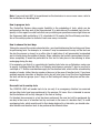
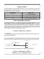
1
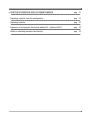
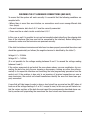
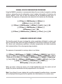
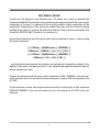
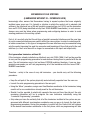
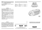
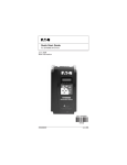
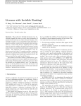
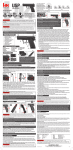
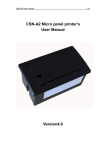
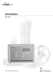
SERVICE GUIDE
CT
CentralTest Beghelli
Intelligent system with self-contained luminaires
CTS
CentralSystem Beghelli
Intelligent system with luminaires connected
to a centralised power supply source
EMERGENCY LIGHTING SYSTEMS
WITH CENTRALISED SELF-TEST CAPABILITY
TABLE OF CONTENTS
• INTRODUCTION
pag
3
• CHECKING THE CONNECTIONS
pag
3
Checking the CT interface connections
pag
3
Checking the CTS interface connections
pag
5
Checking the CT luminaire connections (bus ABC)
pag
8
Checking the connections of CTS luminaires (bus AB)
pag 10
• CONTROL UNIT SET-UP
SET-UP
pag 12
Date
pag 12
Time
pag 12
• TEST PROGRAMMING
pag 13
• SYSTEM CONFIGURATION
CONFIGURATION
pag 15
Method of data transmission between Control Unit and Luminaires
pag 15
System auto-programming procedure
pag 15
Device programming procedure
pag 17
Automatic system configuration procedure
pag 18
Manual device configuration procedure
pag 19
Luminaire division into zones
pag 19
• SYSTEM FUNCTION TEST
pag 20
• SYSTEM EXPANSION
EXPANSION AND/OR MAINTENANCE
pag 21
Removing a device from the configuration
pag 21
Replacing a device
pag 22
Expansion of old systems (luminaires without ID - interface 9410)
pag 23
Notes on checking luminaire functionality
pag 25
INTRODUCTION
The purpose of this guide, provided to all Beghelli Service Centres, is to describe the basic
start-up and maintenance procedures for CentralTest and/or CentralSystem installations with
bus lines. For aspects regarding installation, reference should also be made to the “CT -CTS
System Installation Guide”; for a complete description of the control unit functions, see the
“CT - CTS Control Unit User Manual”.
The description that follows refers to the most complete case where the system includes both
self-powered CT luminaires and CTS luminaires connected to a centralised power source,
namely the SCASE/SA SoccorGroup device.
CHECKING THE CONNECTIONS
In the CT - CTS system we can distinguish among three types of data lines for communication between the control unit and emergency devices:
• Connection between Control Unit and CT and CTS Interfaces achieved with a five-wire bus
cable (A, B, C, D, Common). The interfaces are connected in series via this bus.
• Connection between CT Luminaires and CT Interface achieved with a three-wire bus cable
(A, B, C). The luminaires are connected in parallel via this bus.
• Connection between CTS Luminaires and CTS Interface achieved with a two-wire bus
cable (A, B). The luminaires are connected in parallel via this bus.
CHECKING THE CT INTERFACE CONNECTIONS
Check on incoming 5-wire bus line A, B, C, D, Com.
Disconnect the middle terminal (see figure) “FROM CONTROL UNIT OR PREVIOUS INTERFACE”
and take readings directly at the terminal (the one the bus wires are attached to) to verify that
the voltages are as follows:
Voltage A-common = 3.00Vdc
Voltage B-common = 1.60Vdc
Voltage C-common = 3.00Vdc
Voltage D-common = 1.60Vdc
(if these values fluctuate at some moments it means that the control unit is able to reach the
point).
3
Check on interface input for 5-wire bus line A, B, C, D, Com.
Leaving the middle terminal (see figure) “FROM CONTROL UNIT OR PREVIOUS INTERFACE”
disconnected, take readings directly at the interface terminal to verify that the voltages are as
follows:
Voltage A-common = 3.00Vdc
Voltage B-common = 1.65Vdc
Voltage C-common = 3.00Vdc
Voltage D-common = 1.65Vdc
Check on interface output for bus line A, B, C, D, Com.
Disconnect the output terminal of the 5-line bus leading “TO NEXT INTERFACE”; take readings
directly at the interface terminal to verify that the output voltages are as follows:
Voltage A-common = 3.00Vdc
Voltage B-common = 1.65Vdc
Voltage C-common = 3.00Vdc
Voltage D-common = 1.60Vdc
Check on interface output for bus line A, B, C to luminaires
Disconnect the wires marked A and B from the terminal and take readings directly at the interface terminal to verify that the voltages are as follows (the negative terminal is identified with
the letter C):
Voltage A-C = 3.00Vdc
Voltage B-C = 1.60Vdc
4
230V MAINS SUPPLY
TO INTERFACE
NPA
B
TO LUMINAIRES
C
A
B
C
D
COMMON D
C
COMMON
BA
FROM CONTROL UNIT
OR PREVIOUS INTERFACE
TO NEXT INTERFACE
CHECKING THE CTS INTERFACE CONNECTIONS
Check on incoming 5-wire bus line A, B, C, D, Com.
Disconnect the middle terminal (see figure) “FROM CONTROL UNIT OR FROM PREVIOUS
INTERFACE” and take readings directly at the terminal (the one the bus wires are attached to)
to verify that the voltages are as follows:
Voltage A-common = 3.00Vdc
Voltage B-common = 1.60Vdc
Voltage C-common = 3.0Vdc
Voltage D-common = 1.60Vdc
(if these values fluctuate at some moments it means that the control unit is able to reach the
point).
Check on interface input for 5-wire bus line A, B, C, D, Com.
Leaving the middle terminal (see figure) “FROM CONTROL UNIT OR FROM INTERFACES”
disconnected, take readings directly at the interface terminal to verify that the voltages are as
follows:
Voltage A-common = 3.0Vdc
Voltage B-common = 1.65Vdc
Voltage C-common = 3.0Vdc
Voltage D-common = 1.65Vdc
5
Check on interface output for bus line A, B, C, D, Com.
Disconnect the output terminal of the 5-wire bus leading “TO INTERFACES”; take readings
directly at the interface terminal to verify that the output voltages are as follows:
Voltage A-common = 3.0Vdc
Voltage B-common = 1.65Vdc
Voltage C-common = 3.0Vdc
Voltage D-common = 1.65Vdc
Check on interface output for bus line A, B, C to luminaires
Disconnect the wires marked A and B from the terminal and take readings directly at the interface terminal to verify that the voltages are as follows (the negative terminal is identified with
the letter B):
Voltage A-B = 4.8Vdc
230 Vac N
P
MAGNETIC
CIRCUIT BREAKER
SOCCORGROUP LINE
FROM CONTROL UNIT
FROM INTERFACES
P N
SOCC. PROT.
INTERFACE
DATES
B A
3006
ORD.
P N
230 Vac P
N
A B C D COM.
LED
COM. D C B A
MAINS POWER LINE
P N
TO LUMINAIRES
6
TO INTERFACES
Connection to the SoccorGroup line and circuit breaker
As illustrated in the diagram above, at the top left there is a 4-pole terminal composed of pairs
marked SOCC. (SoccorGroup) and PROT. (protection). The SOCC. input should be connected to
the input of the circuit breaker protecting the safety line, directly in parallel to the line originating from the SA output of the SoccorGroup. Via this connection the interface receives power
directly from the SoccorGroup and can continue to remain powered even if the circuit breaker
trips. The PROT. input should be connected to the output of the circuit breaker protecting the
safety line, directly in parallel to the line that will in turn supply power to the CentralSystem
devices. Via this connection the interface can monitor the power line status downstream from
the circuit breaker and thus inform the Control Unit if the circuit breaker has tripped.
Protection circuit breaker: the control unit is supplied with a safety circuit breaker that differs from the standard circuit breakers used in civil applications simply by virtue of its trip
curve characteristics. When a short circuit occurs during inverter-powered operation the fault
currents the SoccorGroup device is capable of delivering are normally very small (1.25 is the
rated current of SoccorGroup); therefore, to ensure timely tripping of line protections it is
necessary to use breakers with suitable characteristics. The standard protection supplied has
a rated current of 10A and will trip promptly with currents of around 20A (i.e. about double the
rated current). The assumption is that a maximum average load of around 6 - 7 A will be connected to each line. Should the sizing of the protection prove incorrect for the specific application, you are advised to contact the BEGHELLI CUSTOMER SERVICE, which will indicate the
most suitable type of circuit breaker/protection.
Connection to Mains Sensor
As illustrated in the diagram above, at the bottom left there is a 2-pole terminal marked ORD.
This is the input of the ordinary 230Vac power line that the interface uses to monitor the status of the normal mains electricity supply. When the interface fails to detect the presence of
the 230Vac mains supply across these terminals, it will automatically switch over into an
emergency operating status and will command all the CentralSystem luminaires connected to
it to likewise switch over into the emergency mode. All this takes place in 500ms or less.
In order for the emergency system to work correctly, the mains sensor line must be connected to
the local distribution panel that supplies power to the normal lighting system in the area covered
by the interface. In this way, should a power cut be tripped from an area distribution panel due to
a malfunctioning, the emergency system will step in only in the area affected by the failure (thus
providing an advantage similar to that of a system set up with autonomous luminaires).
If the interface controls luminaires installed in several electrical domains (i.e. an interface is not provided for every area power distribution panel, but rather several areas share one interface), using
auxiliary contacts it is nonetheless possible to configure the interface to switch into an emergency
status when any of the mains circuit breakers present on the various area panels has tripped.
7
CHECKING THE CT LUMINAIRE CONNECTIONS (BUS ABC)
To ensure that the system will work correctly it is essential that the following conditions are
complied with:
• Where there is more than one interface, no connections must occur among different data
lines (loops).
• On each luminaire, data line A, B, C must be correctly connected
• There must be no short circuits on data line A, B, C.
In this case as well it is possible to carry out an immediate check directly on the outgoing data
lines of the interfaces (the lines must not be connected to the interface). Before taking measurements, make sure the luminaires are powered correctly.
If the data line between luminaires and interfaces has been properly connected the values read
should be approximately as follows (the negative terminal is identified by the letter C):
Voltage A-C = 3.00Vdc
Voltage B-C = 1.60Vdc
(It is not possible for the voltage reading between B and C to exceed the voltage reading
between A and C).
If the values measured do not match the ones shown above, you can nonetheless try connecting the data line (only the one showing a discrepancy, leaving any other lines disconnected) to its respective interface and launching the auto-programming procedure from the
control unit. If the problem is due only to an inversion of terminal connections on one or
more luminaires, the control unit should nonetheless identify the ones that have been properly connected.
A case that will take longer to solve is when a short circuit has occurred on line ABC (when at
least one of the voltage readings, A-C or B-C, is equal to zero). In this case you will have to isolate the various sections of the data line and repeat the measurements described above section by section until pinpointing the area where the short circuit must have occurred.
8
Further details regarding troubleshooting procedures for bus ABC
+ 5 Vcc
R
A
Rfus
Driver
R
B
Rfus
R
C
Massa
Bus ABC basically consists of a divider of three 10KΩ resistors (R) see figure above. During
communication between the control unit and luminaires, voltage Vab will vary from approximately +4.5V to approximately -4.5V, whereas in rest conditions voltage Vac will be approximately = 3.0 V and Vbc will be approximately =1.6V. Terminal C is a point of reference serving
to maintain a balance in the voltage levels (+4.5V and -4.5V) which could fluctuate due to a
variety of phenomena such as couplings between conductors, inductive transients, etc.…
During communication, by bringing point A to +5Vdc and B to ground (Vab = +4.5) the drivers
will determine transmission of a ONE or, conversely, by bringing point B to +5Vdc and point A
to ground (Vab = -4.5) they will determine transmission of a ZERO. The sequential transmission of ZEROES and ONES is sufficient to convey all messages necessary for managing the
emergency system, according to a Beghelli protocol.
Immediately downstream from terminals A and B there are two 10 Ohm fuse resistors serving
to protect the bus against overvoltage. If 230Vac is applied to the bus line by mistake, these
resistors will usually break and need replacing. Clearly, if there are faulty luminaires and we
measure the voltage across the entire line, we will not realise that the resistors are damaged
because as long as one luminaire is working, the bus will be polarised. To locate the luminaire with an interrupted bus connection we will have to isolate the various nodes and take readings for the individual luminaires connected to the bus.
9
Bus jamming
In particular conditions a situation may occur where luminaires get jammed during a transmission, inducing polarisation of the bus. In such a situation the bus will not permit other
devices connected in parallel to continue normal communication with the control unit. With
the new serial-connected interfaces art. 9413CT the problem will remain limited to the reference interface of the jammed luminaire, whereas with the former parallel-connected interfaces art. 9410 a jammed luminaire could disable communication throughout the system as a
whole. If there are any luminaires jamming the bus, we will typically find higher values (> 3
Volts) when taking readings on the bus itself.
To attempt to unjam the luminaires, disconnect the line downstream from the interface and
try carrying out the following steps:
• Cut off the power supply to the luminaires and then restore it.
• If the problem persists disconnect the power to the backbone involved and allow the batteries to run down to the minimum charge; this will cause the micro to reset and there is a
good probability that the luminaires will be unjammed.
CHECKING THE CONNECTIONS OF CTS LUMINAIRES (BUS AB)
The connection between interfaces and CentralSystem luminaires is made with a two-wire
bus cable marked with the letters A, B. The output terminal of the bus line, again marked A
and B, is situated on the lower side of the interface, in a central position.
As noted above in section 2.2., once the interface has been powered (Socc. input connected
with 230Vac present), you should measure a constant voltage of approx. Vab = 4.8Vdc across
the bus line, without any luminaires connected. As you proceed to connect CentralSystem
luminaires, this polarisation value of the bus tends to fall. Even where the maximum number
of 64 luminaires are connected to an interface, the potential difference between the two wires
Vab should not fall below a value of 3Vdc.
If on completing installation (and with the interface powered) you measure a voltage of Vab=
0 Vdc across the bus line, it means a short circuit has occurred on the AB line. In such a case
you must isolate each section of the data line and repeat the measurements to locate the point
of the short circuit. Until this point is identified, it will not be possible to communicate with any
of the luminaires connected to the interface.
In the case of CTS luminaires, by carrying out a few functional tests you can determine immediately whether the devices have been correctly installed.
10
Check on luminaires with SE connection
Checking these luminaires is a very simple task, which may be summed up in the following
steps:
a) Simulate a blackout within the zone by acting on the mains sensor of the interface to which
the luminaires are connected (i.e. disconnect power at the input terminals of the normal
mains power line to the interface); in this situation all of the luminaires should switch on in
the emergency mode (LEDs of the luminaires off).
b) Bring the system back into normal operating conditions, again via the mains sensor of the
interface; in this situation all of the luminaires should switch back into a standby status (SE)
and go off (LEDs flashing green).
c) Check any individual luminaires that did not behave as described in steps a and b: they
could have problems in the bus line (bus missing, A and B switched over, etc.) or problems
in the circuit power line. If you cannot find any apparent faults, try positioning the luminaire in the place of one that worked correctly and repeat the test. If the luminaire again fails
to respond correctly, the device itself will need to be replaced.
Check on lamps with SA connection
Where luminaires are connected in an SA (maintained) configuration, it is difficult to distinguish normal operation from emergency operation, as in either case the light will be on; the only
visible difference lies in the status of the LED: on in normal conditions and off for the duration
of emergency operation (one hour). Besides checking the status of the LEDs, which may prove
to be a complex, time-consuming procedure, we suggest carrying out the following check:
simulate a blackout within the zone; in this situation all of the luminaires should go on to provide emergency lighting (LEDs on the fixtures off). Bring the system back into normal operating conditions; in this case all of the luminaires should switch back into the SA status and
light up (LEDs flashing green). If the connections are wrong, after around an hour any luminaires that are on because they have switched to emergency operation will go off (these are
the ones that need to be checked) while the ones that have been connected correctly will
remain on. In this case as well, the malfunctioning could be due to problems tied to the bus
line (bus missing, A and B switched over, etc.) or to the circuit power lines. If you cannot find
any apparent faults, try positioning the luminaire in the place of one that worked correctly and
repeat the test. If the luminaire again fails to respond correctly, the device itself will need to
be replaced.
11
CONTROL UNIT SET-UP
The SET-UP menu allows the user to program the following CONTROL UNIT parameters:
DATE
TIME
Automatic PRINTOUTS
LANGUAGE
DATE
With this function the user can set or correct the current date; the calendar function implemented by the CONTROL UNIT also takes into account leap years, so there is no need for
manual adjustments. The sequence of commands to be entered for this function is as follows:
[↵] SET-UP [↵] DATE [↵] dd/mm/yy [↵]
TIME
With this function the user can set or correct the current time; the clock function implemented by the CONTROL UNIT uses a 24-hour notation. The sequence of commands to be entered for this function is as follows:
[↵] SET-UP [↵] TIME [↵] hh:mm [↵]
12
TEST PROGRAMMING
This function is used to program the TIMERS for the FUNCTION and DURATION tests. The initial status of these timers is no programming present, as indicated by a message displayed
on Page “0”. It is thus of extreme importance to program the timers, since otherwise no automatic tests will be performed.
The sequence of commands for programming the Function Test timer is as follows:
[↵] SYStem [↵] PROGramming [↵] TIMER [↵]
FUNCtion [↵] ii [↵] dd/mm/yy [↵] hh:mm
To program the duration test timer, you must enter a sequence of commands similar to that used
for the function test; however, you must also program the function for running duration tests
separately on odd- and even-numbered luminaires. The sequence of commands is as follows:
[↵] SYStem [↵] PROGramming [↵] TIMER [↵]
DURATion [↵] ii [↵] dd/mm/yy [↵] hh:mm
After scheduling the time of execution of the test, you will prompted to specify whether you
wish to use the separate testing function; the following screen will appear:
SEPARATE TEST ODDS-EVENS > NO
YES
NO
If you enable the function you will then be prompted to specify the time lag between the tests
on odd-numbered and even-numbered luminaires; this interval must fall within the range of
1 to 7 days:
INTERVAL ODDS-EVENS DAYS > 01
1 2 3 4 5 6 7 8 9 0
To check that the system has been correctly programmed, request a printout by entering the
following sequence of commands:
[↵] PRINTer [↵] PROGramming [↵] SYStem [↵]
13
Note: If you wish tests NOT to be performed on the luminaires in one or more zones, refer to
the instructions for disabling tests.
How to program tests
The CentralTest System allows ample flexibility in the scheduling of tests, which can be
performed on the days and at the times desired. It is advisable not to schedule tests too frequently: in this regard, we shall note that every switching on operation causes slight stress on
the fluorescent bulb and battery. I.C.E. standards 64.10 require that the efficiency and duration of the safety system be tested at least once every six months.
How to choose the best days
Taking into account the system characteristics, you should determine the best days and times
for performing tests. For example, in a cinema it may be convenient to carry out the tests on
the day the cinema is closed, in an office late at night when it will presumably be deserted
and in a hotel during the middle of the day. Since a duration test entails running down the batteries completely, it would be preferable for this test to take place in the morning to allow
recharging during the day.
If, for example, you think it is a good idea for function tests to be run on Saturdays, make sure
to specify a starting date that falls on a Saturday and choose a period of 7 days or one that is
a multiple of 7. Similar considerations apply for the duration tests, which will be scheduled by
number of weeks (rather than by number of days as in the case of function tests). If you have
enabled separate execution of duration tests you will also have to set the time lag between
the tests on the two groups (max 7 days) so that testing will always take place on the scheduled day.
Be careful not to overlap tests
The CONTROL UNIT will enable tests to be run only if no emergency situation has occurred
and no other tests have been performed in the previous 24 hours: this is intended to ensure
that the batteries will be fully charged at the time of testing.
If a blackout has occurred or a test has been performed, the new test will be postponed (by
one day in the case of a function test, by one week in the case of a duration test). To avoid
overlapping tests, which would result in their being deferred to a later date, you should schedule function and duration tests to be performed on different dates.
14
SY STEM CONFIGURATION
METHOD OF DATA TRANSMISSION BETWEEN CONTROL UNIT AND LUMINAIRES
CentralTest - CentralSystem communication is based on a query-response exchange between
the CONTROL UNIT and each individual luminaire, carried out in a sequential manner (polling).
The Control Unit microprocessor outputs messages along the data transmission line. Each
message will reach all the luminaires but be recognised by only one of them, depending on
the code assigned during the start-up phase. The microprocessor of the lighting fixture interrogated will send back a reply message, which will be analysed by the Control Unit.
SYSTEM AUTO-PROGRAMMING PROCEDURE
AUTO-PROGRAMMING is a procedure designed to make system installation and start-up
easier. As of its introduction, there is no longer any need to program the luminaires before
installing them: this operation is automatically performed by the CentralTest - CentralSystem
Control Unit (using the 6-digit identification code). After being programmed the luminaire will
also be memorised in the configuration table of the control unit. The attribution of system
coordinates starts off from the first zone and proceeds with subsequent zones when the 64th
installed luminaire is reached.
The auto-programming procedure can also be applied when new unprogrammed luminaires
are added to an already existing or already programmed system. The procedure is structured
in such a way as to recognise and configure the already programmed luminaires present
within the system. Thereafter the newly installed luminaires will be programmed and zones
filled, starting from the first. This prevents errors from arising due to the attribution of the
same system coordinates to two different lighting fixtures, a problem that was previously
likely to occur when a system was expanded and luminaires were programmed manually. In the
case of a CTS system or combined CT/CTS system, auto-programming is preceded by installation of one or more Soccorgroup devices, which involves enabling the auxiliary ports (CN2 CN3
see installation guide) and programming the Soccorgroup address.
The sequence of commands to be entered for this function is as follows:
[↵] SYStem [↵] CONFIGuration [↵] AUTOPR [↵]
The procedure is divided into three phases, whose execution will be indicated by three different messages which appear in the command line of the control unit display. While the AUTOPROGRAMMING function is in progress, another function called SKIP will be available to the
user; it will take on different meanings depending on the phase currently underway.
15
The first phase of the procedure is signalled by the appearance of the following screen:
CONFIGURATION IN PROGRESS >
SKIP ID xxxxxx dev dd zone zz num.nn
During this phase the control unit will search for any already programmed luminaires within
the system (this will occur in the case of a system that is being expanded); the search will be
conducted sequentially, one zone at a time. Selecting and confirming the SKIP option will
cause the control unit to abandon the current zone and move on to the next.
In the second phase the control unit will program the unprogrammed luminaires present in
the system; system coordinates will be attributed starting from the first zone and all free
peripheral numbers will be used. The control unit will display the following screen:
AUTO-PROGRAMMING IN PROGRESS >
SKIP ID xxxxxx dev dd zone zz num.nn
Selecting and confirming the SKIP option during this phase will cause the control unit to move
on to the next phase.
The third and last phase enables the control unit to acquire the 6-digit identification codes of
the already programmed luminaires detected during the first phase: the control unit display
will show the following screen:
ID CAPTURE IN PROGRESS >
SKIP ID xxxxxx dev dd zone zz num.nn
In this case selecting and confirming the SKIP option will bring the auto-programming procedure to an end.
16
DEVICE TYPE CODE
As may be observed in the messages that appear on the auto-programming screen, the
abbreviation dev also appears: this allows the type of device currently being programmed to
be identified by means of a 2-digit code:
DEVICE CODE
DEVICE TYPE
01
02
05
06
CENTRALTEST LUMINAIRES
TELE I/O
CENTRALSYSTEM LUMINAIRES
CENTRALSYSTEM INTERFACES
DEVICE PROGRAMMING PROCEDURE
Programming of luminaires is an operation that typically takes place during the system
start-up phase in the case of luminaires without an identification code. This operation
may also prove necessary, however, when an existing system is expanded or a luminaire is
replaced and the user does not wish to use the auto-programming procedure. This command
can be entered only when the CONTROL UNIT is not configured; if this is not the case it will
first be necessary to carry out the following procedure:
[↵] SYStem [↵] CONFIGuration [↵] RESET [↵]
It is MANDATORY to carry out luminaire programming procedure with only one luminaire connected to the CONTROL UNIT.
Use a 3-wire cable with a 9-pole miniD connector (for the connection to the control unit) specifically made to match up directly with the pins of the miniD connector on the control unit:
Pin 5 -> C
Pin 2 -> B
Pin 1 -> A
CONTROL UNIT
The sequence of commands for programming the luminaire is the following:
[↵] SYStem [↵] PROGramming [↵] DEVice [↵]
LUMInaire [↵] zz [↵] ll [↵] duration [↵] DO [↵]
17
IMPORTANT:
If the programming procedure is launched when the CONTROL UNIT is connected to the
system, this may cause all of the lighting fixtures present to be assigned the same
address code. In such a case it would be necessary to reprogram each individual lighting fixture. Though there are procedures designed to avoid all of this, it is advisable to
entrust this type of operation to qualified personnel.
AUTOMATIC SYSTEM CONFIGURATION PROCEDURE
The system configuration procedure was used in the first CentralTest systems, where the
luminaires did not have individual IDs, but rather had to be programmed manually one at time:
that is, each was manually assigned a ZONE and NUMBER identifying its position within the
zone. In this procedure the CONTROL UNIT will interrogate all of the possible addresses and
only the addresses that respond will be memorised as luminaires (note that if you disconnect a programmed luminaire from the system and attempt to configure it manually by
calling it at its address, if the control unit does not find it, it will automatically delete
the luminaire from its internal configuration table). This procedure thus serves to memorise all the previously programmed system components in the Control Unit configuration table.
The sequence of commands to be entered for this function is as follows:
[↵] SYStem [↵] CONFIGuration [↵] START [↵]
With the current software versions the control unit requires the luminaires to be assigned a
ZONE-NUMBER - ID CODE
It is extremely important for all the devices present in the system to be configured with
a zone and number: if one or more luminaires within the system are not programmed
during this procedure the “virgin” (unprogrammed) ones will always respond and the
operation will fail.
Also in the case where there are luminaires id 000000 or id ffffff (programmed luminaires) within the system the configuration procedure will not be successful.
18
MANUAL DEVICE CONFIGURATION PROCEDURE
Using the MANUAL procedure is recommended where the user wishes to expand an existing
system or change the current configuration, since it enables interrogation of luminaires at a
specific address. In this case as well the luminaire will be considered present only if it
responds. The sequences of commands to be entered for this function are the following:
[↵] SYStem [↵] CONFIGuration [↵] MANual [↵]
LUMInaire [↵] zz [↵] ll [↵] DO
[↵] SYStem [↵] CONFIGuration [↵] MANual [↵] TeleIO [↵] zz [↵] DO
[↵] SYStem [↵] CONFIGuration [↵] MANual [↵]
SOCCorgroup [↵] zz [↵] DO
[↵] SYStem [↵] CONFIGuration [↵] MANual [↵] CTS int [↵] zz [↵] DO
LUMINAIRE DIVISION INTO ZONES
This function permits the user to change the system coordinates attributed to a device and
thus to move the latter within the logical arrangement of the devices making up the system.
This allows such maintenance operations as system reorganisation into zones (necessary
after implementation of the auto-programming procedure).
The sequence of commands for moving a device is as follows:
[↵] SYStem [↵] MAINTenance [↵] "MOVE [↵] LUMInaire [↵] ZONE/N [↵] zz [↵] ll [↵]
zz [↵] ll [↵] DO [↵] [↵] SYStem [↵] MAINTenance [↵] "MOVE [↵] LUMInaire [↵] ID [↵]
ID [v] zz [↵] ll [↵] DO [↵] [↵] SYStem [↵] MAINTenance [↵] "MOVE [↵] TeleIO [v] zz
[↵] zz [↵] DO [↵] [↵] SYStem [↵] MAINTenance [↵] "MOVE [↵] CTS int [↵] zz [↵] zz
[↵] DO [↵] [↵] SYStem [↵] MAINTenance [↵] "MOVE [↵]
SOCCorgroup [↵] zz [↵] zz [↵] DO [↵]
When you select a device by means of its 6-digit identification code, the control unit will
display the system coordinates currently programmed for the luminaire.
Note: If you attempt to move a device into a position occupied by another device, a message
will be displayed informing you that the operation has failed because of a selection error.
19
SY STEM FUNCTION TEST
The user can run a check on the CentralTest system at any time, irrespective of when automatic tests are scheduled to be run. Both function and duration tests can obviously be performed. IMPORTANT: function tests take just a few minutes (the luminaires will stay on for 1')
while duration tests take longer (the luminaires will stay on for a time equal to their programmed duration).
On completing the system start-up, you are advised to carry out only a system function test,
deferring the check on battery storage capacities until the first automatic duration test.
The sequence of commands for carrying out the above tests is as follows:
[↵] MANual [↵] FUNCtion [↵] zz [↵] DO [↵]
[↵] MANual [↵] DURATion [↵] zz [↵] DO [↵]
Manual tests can be suspended while in progress by means of the following procedure:
CANCel
Even in this case a final test report will be printed out, but it will include a warning that the
test was aborted.
20
SY STEM EXPANSION AND/OR MAINTENANCE
REMOVING A DEVICE FROM THE CONFIGURATION
This command enables you to delete a device from the system. Applying this function to a
device will have the effect of erasing its programming (it will be restored to an unprogrammed status) and inhibiting its emergency function. The device will obviously also be deleted
from the control unit configuration table. A device can be selected either by means of its
system coordinates or its 6-digit identification code.
The sequence of commands for deleting a device from the system is as follows:
[↵] SYStem [↵] MAINTenance [↵] REMOVE [↵]
LUMInaire [↵] ZONE/N [↵] zz [↵] ll [↵] DO [↵]
[↵] SYStem [↵] MAINTenance [↵] REMOVE [↵]
LUMInaire [↵] ID [↵] ID [↵] DO [↵]
[↵] SYStem [↵] MAINTenance [↵] REMOVE [↵] TeleIO [↵] zz [↵] DO [↵]
[↵] SYStem [↵] MAINTenance [v] REMOVE [↵]
SOCCorgroup [↵] zz [↵] DO [v]
[↵] SYStem [↵] MAINTenance [↵] REMOVE [↵] CTS int [↵] zz [↵] DO [↵]
The system coordinates of a device that has been removed will of course become available
for reuse by another device.
If the remove function is applied to a device the control unit is no longer able to communicate with, a message will be displayed that the procedure has failed but the device will nonetheless be deleted from the control unit configuration table.
IMPORTANT:
After a device has been deleted from the system it must be physically removed: leaving
it in place would cause obstacles to subsequent maintenance operations.
21
REPLACING A DEVICE
A device can be replaced in two different ways. The device can simply be replaced with
another, provided that the new device has previously been programmed with the same system
coordinates as the one it is replacing (in this way the previous system coordinates will be
maintained). Programming of the new device cannot take place with the luminaire already
installed in the system as a whole, but rather only with that single luminaire connected to the
CentralTest CONTROL UNIT. Therefore it is necessary to:
remove the old luminaire from the system, which may be achieved in 2 ways - either by using
the remove command:
[↵] SYStem [↵] MAINTenance [↵] REMOVE [↵]
LUMInaire [↵] ZONE/N [↵] zz [↵] ll [↵] DO [↵]
[↵] SYStem [↵] MAINTenance [↵] REMOVE [↵]
LUMInaire [↵] ID [↵] ID [↵] DO [↵]
- or by electrically disconnecting the luminaire and configuring it manually by calling it at its
address. If the control unit does not find it, it will automatically delete the luminaire from its
internal configuration table.
Program the luminaires with the same system coordinates (ZONE - NUMBER) as the old ones;
in this way the control unit will have the same references as before, with the exception of the
ID CODE.
Fit the luminaires in place and configure them manually by calling them at their respective
ZONE AND NUMBER: in this way the control unit can also retrieve the ID CODE of the new
luminaire.
22
EXPANSION OF OLD SYSTEMS
(LUMINAIRES WITHOUT ID - INTERFACE 9410)
Increasingly often, owners find themselves having to expand systems that were originally
installed some years ago. It is typically a situation in which the control unit is obsolete (old
software), the interfaces are of the old, parallel-connected type (art. 9410) and the luminaires
have no ID CODE (being identified sole by their ZONE-NUMBER coordinates); in such circumstances care must be taken when programming and configuring devices in order to avoid
creating problems in the existing system.
First of all, we shall note that the old type of parallel-connected interfaces and the new type
of serial-connected interfaces can coexist within the same system: in order to maintain parallel cable connections, in this type of arrangement the new interfaces may be connected using
only the central incoming five-pole line connector and branching off from that point to the next
interface (i.e. the 5-wire bus will no longer be connected on the input and output side).
First-generation luminaires without ID
If the luminaires already installed are effectively very old (1990-1996) it will not be possible
to carry out the programming procedure for new devices leaving them in parallel with the old
ones. The old luminaires may in fact not have E2PROM enabling: therefore, if you use inappropriate commands you will risk programming all of the luminaires with the same ZONE NUMBER coordinates.
Therefore - solely in the case of very old luminaires - you should carry out the following
procedure:
• Keep the old part of the system physically and electrically separate from the new one.
• Launch the auto-programming procedure in the new part.
• Using the “Move” procedure, assign new Zone/Number coordinates to the luminaires, being
careful not to use combinations already used for the old luminaires.
• Should it not be possible to electrically separate the new part from the old part, the only
remaining alternative will be to program the new luminaires individually using the
“Luminaire Programming” procedure.
• Only when you have the certainty that all of the luminaires installed in the system are programmed with different zone/number coordinates can you go on to launch the final autoprogramming procedure. During this procedure, in actual fact, the Control Unit will retrieve
all the device zone/number coordinates in the first phase, while no programming will take
23
place during the second phase, since the devices are all already programmed, and in the
third phase the ID codes of the new devices will be memorised. Old luminaires will be identified in printouts with CODE:000000.
Second-generation luminaires without ID
If the luminaires already installed are of a more recent generation (1996-1999), you can carry
out the programming procedure for new devices leaving them in parallel with the old ones.
Therefore, in this case carry out the following procedure:
• Launch the auto-programming procedure.
• During this procedure the Control Unit will use all the functions offered by the procedure
itself: in the first phase it will retrieve all the zone/number coordinates of already programmed devices, in the second phase the new devices will be programmed and in the third
phase the ID codes of the luminaires configured in the first phase will be memorised. Old
luminaires (without an ID code) will be identified in printouts with CODE:000000.
• Using the “Move” procedure, assign new Zone/Number coordinates to the luminaires, being
careful not to use combinations already used for the old luminaires.
24
NOTES ON CHECKING LUMINAIRE FUNCTIONALITY
In the case of very old luminaires, due to lack of maintenance the devices could fall into critical conditions causing them to lose their programming. Therefore, the first check to be
performed is a sample inspection of luminaires.
• check that the luminaire, when connected to the mains, at least has its LED on;
• disconnect the power supply and check whether the luminaire functions properly;
• check the state of the battery and circuit;
• check the bus output of the luminaire (power the luminaire without connecting the bus line
and check that the values measured across the bus terminals are as follows: Vac=3Vdc and
Vbc=1.5Vdc);
Old luminaires may have lost their programming. To find out whether this has occurred, connect only the luminaire you want to check to the control unit (using the brackets employed
during programming) and after resetting the control unit, try to configure the luminaire using
the manual procedure. If the luminaire is still programmed the control unit should configure
it normally. If the configuration procedure fails, it means that the luminaire is no longer programmed.
In such a case, it is advisable to try reprogramming it by carrying out the same steps as in the
case of new luminaires and again attempt to launch the manual configuration procedure. If
even this attempt is unsuccessful, the luminaire is to be considered broken.
25
334.900.503
www.beghelli.com
BEGHELLI S.p.A. - Via Mozzeghine 13, 15 - 40050 MONTEVEGLIO (BO)
Tel. 051 9660411 - Fax 051 9660444