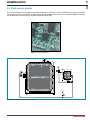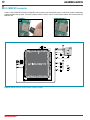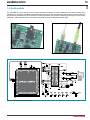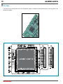
1
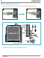
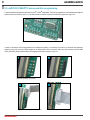
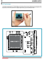
All MikroElektronika´s development systems represent irreplaceable
tools for programming and developing microcontroller-based devices.
Carefully chosen components and the use of machines of the last
generation for mounting and testing thereof are the best guarantee of
high reliability of our devices. Due to simple design, a large number of
add-on modules and ready to use examples, all our users, regardless
of their experience, have the possibility to develop their project in a fast
and efficient way.
User manual
Development system
If you have any questions, comments or business proposals, do not hesitate to contact us at [email protected]
If you are experiencing some problems with any of our products or just need additional information, please place your ticket at
www.mikroe.com/en/support
If you want to learn more about our products, please visit our website at www.mikroe.com
mikroMMB for dsPIC33
™
DISCLAIMER
All the products owned by MikroElektronika are protected by copyright law and international copyright treaty.
Therefore, this manual is to be treated as any other copyright material. No part of this manual, including
product and software described herein, may be reproduced, stored in a retrieval system, translated or
transmitted in any form or by any means, without the prior written permission of MikroElektronika. The
manual PDF edition can be printed for private or local use, but not for distribution. Any modification of this
manual is prohibited.
TO OUR VALUED CUSTOMERS
I want to express my thanks to you for being interested in our products and for having confidence in
Mikroelektronika.
The primary aim of our company is to design and produce high quality electronic products and to constantly
improve the performance thereof in order to better suit your needs.
Nebojsa Matic
General Manager
MikroElektronika provides this manual ‘as is’ without warranty of any kind, either expressed or implied,
including, but not limited to, the implied warranties or conditions of merchantability or fitness for a particular
purpose.
MikroElektronika shall assume no responsibility or liability for any errors, omissions and inaccuracies that may
appear in this manual. In no event shall MikroElektronika, its directors, officers, employees or distributors be
liable for any indirect, specific, incidental or consequential damages (including damages for loss of business
profits and business information, business interruption or any other pecuniary loss) arising out of the use
of this manual or product, even if MikroElektronika has been advised of the possibility of such damages.
MikroElektronika reserves the right to change information contained in this manual at any time without prior
notice, if necessary.
HIGH RISK ACTIVITIES
The products of MikroElektronika are not fault – tolerant nor designed, manufactured or intended for use or
resale as on – line control equipment in hazardous environments requiring fail – safe performance, such as
in the operation of nuclear facilities, aircraft navigation or communication systems, air traffic control, direct
life support machines or weapons systems in which the failure of Software could lead directly to death,
personal injury or severe physical or environmental damage (‘High Risk Activities’). MikroElektronika and its
suppliers specifically disclaim any expressed or implied warranty of fitness for High Risk Activities.
TRADEMARKS
The Mikroelektronika name and logo, the Mikroelektronika logo, mikroC, mikroC PRO, mikroBasic, mikroBasic PRO, mikroPascal, mikroPascal PRO, AVRflash, PICflash, dsPICprog, 18FJprog, PSOCprog, AVRprog, 8051prog, ARMflash, EasyPIC5, EasyPIC6, BigPIC5, BigPIC6, dsPIC PRO4, Easy8051B, EasyARM,
EasyAVR5, EasyAVR6, BigAVR2, EasydsPIC4A, EasyPSoC4, EasyVR Stamp LV18FJ, LV24-33A, LV32MX,
PIC32MX4 MultiMedia Board, PICPLC16, PICPLC8 PICPLC4, SmartGSM/GPRS, UNI-DS are trademarks
of Mikroelektronika. All other trademarks mentioned herein are property of their respective companies.
All other product and corporate names appearing in this manual may or may not be registered trademarks
or copyrights of their respective companies, and are only used for identification or explanation and to the
owners’ benefit, with no intent to infringe.
The Microchip name and logo, the Microchip logo, Accuron, dsPIC, KeeLoq, microID, MPLAB, PIC, PICmicro, PICSTART, PRO MATE,
PowerSmart, rfPIC and SmartShunt are registered trademarks of Microchip Technology Incorporated in the U.S.A and other countries.
©MikroelektronikaTM, 2010, All Rights Reserved.
3
page
mikroMMB for dsPIC33
TABLE OF CONTENTS
General information .......................................................................................................................... 4
Key features ..................................................................................................................................... 5
1.0. Development system connection .............................................................................................. 6
2.0. dsPIC33FJ128GP710 microcontroller ....................................................................................... 7
3.0. dsPIC33FJ128GP710 microcontroller programming ................................................................. 8
4.0. Touch Screen ............................................................................................................................10
5.0. Flash Memory Module ..............................................................................................................11
6.0. MMC/SD Connector ..................................................................................................................12
7.0. Audio Module ............................................................................................................................13
8.0. Pads ..........................................................................................................................................14
MikroElektronika
page
4
mikroMMB for dsPIC33
General information
The mikroMMB for dsPIC33 is a compact development system which provides a convenient platform for development of devices with
multimedia contents. The central part of the system is a 16-bit microcontroller dsPIC33FJ128GP710 that is programmed with the
LV24-33 external programmer from Mikroelektronika or with ICD2® and ICD3® programmers from Microchip®. The mikroMMB for
PIC33 features integrated modules such as audio module, TFT 320x240 touch screen display, USB connector for communication with
the microcontroller, flash memory and MMC/SD card connector.
Multimedia board may be used as
a stand-alone control device
TFT 320X240 display with a
palette of 262.000 colors is used
to display graphic contents
Touch panel is part of TFT display.
Together they form a touch screen
module
The possibility of reading MMC/
SD memory cards
The microcontroller is programmed with the relevant program that comes
along with the external programmer you choose. The programmer is ordered
separately from the development system.
Package contains:
Development system: CD:
Cables:
Documentation:
mikroMMB for PIC33
product CD with the relevant software
USB cable
mikroMMB for PIC33 manual
System Specification:
Power supply:
over a USB cable (5V DC)
Power consumption: 50mA in idle state (when on-board modules are off)
Dimensions:
8 x 6cm (3.14 x 2.36 inch)
Weight:
~150g (0.33 lbs)
MikroElektronika
5
page
mikroMMB for dsPIC33
Key features
1.
2.
3. 4. Pads
TFT 320x240 display
Pads used to connect ICD2 and ICD3 programmers
Pads used to connect the LV24-33 programmer
5. Pads
6. Headphone connector
7. USB MINI-B connector
1
2
3
7
4
6
5
MikroElektronika
page
6
mikroMMB for dsPIC33
1.0. Development system connection
Connect the development system to a PC via a USB cable, Figure 1-1. The TFT display will be automatically turned on.
A
B
Figure 1-1: Powering the development system
Figure 1-2: USB connector and microcontroller connection schematic
The USB connector is used to access the UART2 module built into the microcontroller.
MikroElektronika
7
page
mikroMMB for dsPIC33
2.0. dsPIC33FJ128GP710 microcontroller
The mikroMMB for PIC33 development system comes with the dsPIC33FJ128GP710 microcontroller. This high-performance 16-bit
microcontroller with its integrated modules and in combination with other on-board modules is ideal for multimedia applications.
Key features of the microcontroller:
- Up to 40 MIPS Operation;
- 16-bit wide data path
- 24-bit wide instructions
- Linear program memory addressing up to 4M
instruction words
- Linear data memory addressing up to 64 Kbytes
- 83 base instructions: mostly 1 word/1 cycle
- Sixteen 16-bit General Purpose Registers; etc.
Figure 2-1: dsPIC33FJ128GP710 microcontroller
Pads (HDR1 and HDR2) are used for connecting the microcontroller pins to some additional device or a proto board. These pads are
placed along the two opposite sides of the development system.
MikroElektronika
page
8
mikroMMB for dsPIC33
3.0. dsPIC33FJ128GP710 microcontroller programming
The microcontroller is programmed with LV24-33, ICD2® or ICD3® programmer. The LV24-33 programmer is connected to the development
system via the CN1 connector, Figure 3-2. The CN9 connector is used to connect ICD2 and ICD3 programmers, Figure 3-4.
Figure 3-1: CN9 and CN1 connectors
In order to connect the LV24-33 programmer to the development system, it is necessary to provide a 1x5 connector that should be
soldered on the CN1 connector. When plugging in the programmer’s IDC10 connector, make sure that connector pins MCU RB6
(PGC), MCU RB7 (PGD) and MCU MCLR are plugged into the CN1 connector, Figure 3-3.
A
B
Figure 3-2: Soldering 1x5 connector
A
Figure 3-3: Connecting LV24-33 programmer
MikroElektronika
B
9
A
page
mikroMMB for dsPIC33
B
Figure 3-4: Connecting ICD2 connector
A
B
Figure 3-5: Connecting ICD2 or ICD3 programmer
In order to enable the ICD2 and ICD3 programmers to be connected to the development system, it is necessary to provide the
appropriate connector such as the ICD2 CONNECTOR BOARD. This connector should be first soldered on the CN9 connector, Figure
3-4. Then you should plug in the ICD2 or ICD3 programmer into it, Figure 3-5.
Figure 3-6: Connectors CN1 and CN9 and microcontroller connection schematic
MikroElektronika
page
10
mikroMMB for dsPIC33
4.0. Touch screen
The development system features a TFT 320x240 display covered with a sensitive touch panel. Together they form a functional unit called
a touch screen. It enables data to be entered and displayed at the same time. The way of entering and displaying data depends on the
program loaded into the microcontroller. The TFT display is capable of showing data in 262.000 different colors.
Figure 4-1: Touch screen
Figure 4-2: Touch screen connection schematic
MikroElektronika
11
page
mikroMMB for dsPIC33
5.0. Flash memory module
Since multimedia applications are getting increasingly demanding, it is necessary to provide additional memory space to be used for
storing programs by the microcontroller. The flash memory module enables the microcontroller to use additional 8Mbit flash memory.
It is connected to the microcontroller via the Serial Peripheral Interface (SPI).
Figure 5-1: Flash memory module
Figure 5-2: Flash memory module connection schematic
MikroElektronika
page
12
mikroMMB for dsPIC33
6.0. MMC/SD connector
There is a built-in MMC/SD connector for MMC/SD cards provided on the development system. It enables the system to additionally
expand available memory space. The Serial Peripheral Interface (SPI) is used for communication between the microcontroller and
MMC/SD card.
A
Figure 6-1: Inserting MMC/SD card
Figure 6-2: MMC/SD connector and microcontroller connection schematic
MikroElektronika
B
13
page
mikroMMB for dsPIC33
7.0. Audio module
The mikroMMB for PIC33 features an audio module providing an interface for stereo headphones.This module enables audio
reproduction by using stereo headphones connected to the system via a 3.5mm connector CN6. Volume as well as other functions of
this module are controlled by the microcontroller from within the software using the Serial Peripheral Interface (SPI). Communication
between the audio module and the microcontroller is performed via the Serial Peripheral Interface (SPI).
Figure 7-1: Audio connectors
Figure 7-2: Audio connector with headphones connected
Figure 7-3: Audio module connection schematic
MikroElektronika
page
14
mikroMMB for dsPIC33
8.0. Pads
The access to the microcontroller pins on the development system is enabled via pads provided along the two long sides of the
development system.
Figure 8-1: Pads
Figure 8-2: Pads and microcontroller connection schematic
MikroElektronika
DISCLAIMER
All the products owned by MikroElektronika are protected by copyright law and international copyright treaty.
Therefore, this manual is to be treated as any other copyright material. No part of this manual, including
product and software described herein, may be reproduced, stored in a retrieval system, translated or
transmitted in any form or by any means, without the prior written permission of MikroElektronika. The
manual PDF edition can be printed for private or local use, but not for distribution. Any modification of this
manual is prohibited.
TO OUR VALUED CUSTOMERS
I want to express my thanks to you for being interested in our products and for having confidence in
Mikroelektronika.
The primary aim of our company is to design and produce high quality electronic products and to constantly
improve the performance thereof in order to better suit your needs.
Nebojsa Matic
General Manager
MikroElektronika provides this manual ‘as is’ without warranty of any kind, either expressed or implied,
including, but not limited to, the implied warranties or conditions of merchantability or fitness for a particular
purpose.
MikroElektronika shall assume no responsibility or liability for any errors, omissions and inaccuracies that may
appear in this manual. In no event shall MikroElektronika, its directors, officers, employees or distributors be
liable for any indirect, specific, incidental or consequential damages (including damages for loss of business
profits and business information, business interruption or any other pecuniary loss) arising out of the use
of this manual or product, even if MikroElektronika has been advised of the possibility of such damages.
MikroElektronika reserves the right to change information contained in this manual at any time without prior
notice, if necessary.
HIGH RISK ACTIVITIES
The products of MikroElektronika are not fault – tolerant nor designed, manufactured or intended for use or
resale as on – line control equipment in hazardous environments requiring fail – safe performance, such as
in the operation of nuclear facilities, aircraft navigation or communication systems, air traffic control, direct
life support machines or weapons systems in which the failure of Software could lead directly to death,
personal injury or severe physical or environmental damage (‘High Risk Activities’). MikroElektronika and its
suppliers specifically disclaim any expressed or implied warranty of fitness for High Risk Activities.
TRADEMARKS
The Mikroelektronika name and logo, the Mikroelektronika logo, mikroC, mikroC PRO, mikroBasic, mikroBasic PRO, mikroPascal, mikroPascal PRO, AVRflash, PICflash, dsPICprog, 18FJprog, PSOCprog, AVRprog, 8051prog, ARMflash, EasyPIC5, EasyPIC6, BigPIC5, BigPIC6, dsPIC PRO4, Easy8051B, EasyARM,
EasyAVR5, EasyAVR6, BigAVR2, EasydsPIC4A, EasyPSoC4, EasyVR Stamp LV18FJ, LV24-33A, LV32MX,
PIC32MX4 MultiMedia Board, PICPLC16, PICPLC8 PICPLC4, SmartGSM/GPRS, UNI-DS are trademarks
of Mikroelektronika. All other trademarks mentioned herein are property of their respective companies.
All other product and corporate names appearing in this manual may or may not be registered trademarks
or copyrights of their respective companies, and are only used for identification or explanation and to the
owners’ benefit, with no intent to infringe.
The Microchip name and logo, the Microchip logo, Accuron, dsPIC, KeeLoq, microID, MPLAB, PIC, PICmicro, PICSTART, PRO MATE,
PowerSmart, rfPIC and SmartShunt are registered trademarks of Microchip Technology Incorporated in the U.S.A and other countries.
©MikroelektronikaTM, 2010, All Rights Reserved.
All MikroElektronika´s development systems represent irreplaceable
tools for programming and developing microcontroller-based devices.
Carefully chosen components and the use of machines of the last
generation for mounting and testing thereof are the best guarantee of
high reliability of our devices. Due to simple design, a large number of
add-on modules and ready to use examples, all our users, regardless
of their experience, have the possibility to develop their project in a fast
and efficient way.
User manual
Development system
If you have any questions, comments or business proposals, do not hesitate to contact us at [email protected]
If you are experiencing some problems with any of our products or just need additional information, please place your ticket at
www.mikroe.com/en/support
If you want to learn more about our products, please visit our website at www.mikroe.com
mikroMMB for dsPIC33
™