1
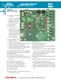
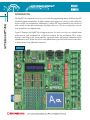
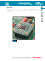
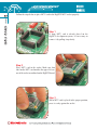
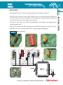
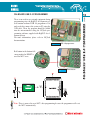
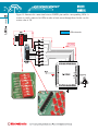
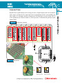
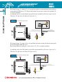
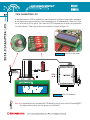
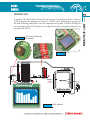
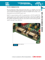
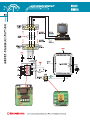
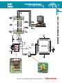
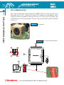
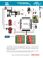
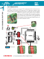
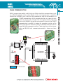
CONTENTS
BigPIC5 KEY FEATURES
CONNECTING THE SYSTEM
INTRODUCTION
Switches
Jumpers
MCU Card
MCU Ports
Power Supply
On-board USB 2.0 Programmer
MikroICD (Hardware In-Circuit Debugger)
LEDs
Push Buttons
2x16 Character LCD
Graphic LCD
Touch Panel
RS-232 Communication
PS/2 Communication
DS1820 Digital Thermometer
A/D Converter Input
Direct Port Access
MMC/SD (Multimedia Card)
CAN Communication
RS485 Communication
D/A Converter
Real Time Clock
4
5
6
7
8
9
11
12
13
14
15
17
20
21
22
23
26
27
28
30
32
34
35
36
37
4
BigPIC5
KEY FEATURES
1. External power supply of 8v
to 16v AC/DC.
2. Selectable external and USB
power supply. When using
USB port, there is no need
for external power supply.
3. Power on/off switch.
4. USB connector.
5. Very fast and flexible onboard USB programmer with
mikroICD (In-Circuit Debugger). Its key feature is ability
to upgrade. By downloading
a new software, it will be
possible to program new
MCUs in coming years.
6. MCU Card supports all 64
and 80 pin PIC MCUs.
7. Direct port access connectors.
8. Jumpers to determine input pin performance in idle state
(connected to pull-up or pull-down resistor).
9. Switch group SW1 enables pull-up/pull-down resistors
on PORTA pins RA0-RA5, reference voltage for MCUs
A/D converter and LCD/GLCD backlight.
10. 67 push-buttons allow control of all the microcontroller pins.
11. Jumper to select high or low state of pins on push-button press.
12. RESET push-button.
13. Each I/O pin corresponds to one LED.
14. Switch group SW5 allows all LEDs on ports A, B, C, D,
E, F, G, H and J to be connected or disconnected from
MCU pins.
15. On-board real-time clock/calendar.
16.
17.
18.
19.
20.
21.
22.
16x2 characters LCD display connector.
Potentiometer for LCD contrast adjustment.
Graphic LCD display (GLCD) connector.
Potentiometer for GLCD contrast adjustment.
Touch panel connector.
Touch panel controller.
DS1820 temperature sensor allows temperature measurement with 0.5 C accuracy.
23. 12-bit D/A connector.
24. RS-485 communication module.
25. CAN communication module.
26. Two RS232 communication ports- RS232 A and RS232 B.
27. PS/2 keyboard connector.
28. For testing purposes, several pins on PORTA and PORTF
can be connected to potentiometers P3 and P4 and as
such can be used as inputs for measurement variable
voltages set by these potentiometers.
29. Precise 4.096V voltage reference.
30. MMC/SD slot for multimedia cards with up to 2GB storage space.
31. Switch group SW2 enables real-time clock alarm signal,
touch panel controller and RS-485 controller.
32. Switch group SW3 enables PS/2 keyboard connection,
CAN communication, D/A converter and MMC/SD card.
33. Switch group SW4 enables SPI and I2C communication
module and pull-up/pull-down resistors on some PORTF
pins.
Apart from this manual, development system box contains development system, product CD,
USB cable, RS232 cable and user's manuals for PICflash programmer, mikroICD Debugger
and Installing USB drivers. In order to use BigPIC5 properly, it is necessary to go through the
following steps:
Step no.1
Take development system and product CD out of the box. First of all, insert
the product CD into CD drive. Do not connect development system to PC
yet.
Step no.2
Install PICflash programmer software to enable a program to be transferred
from PC to the microcontroller chip. Installation instructions are contained
in ‘PICflash programmer’ manual.
Step no.3
Install USB drivers on your PC to enable programmer's hardware to operate properly on BigPIC5 board. For detailed installation instructions refer
to 'Installing USB drivers' manual.
Step no.4
Connect BigPIC5 to PC using USB cable. Please use one of USB ports on
the back of the PC because they are directly connected to the computer
motherboard.
The first time you switch the BigPIC5 on, your PC will automatically detect
a new hardware. You will be immediately prompted whether Windows
should search for new drivers update or not. Select the option 'No, not this
time' and click 'Next'. Another window appears, click 'Next' and the operating system will automatically find the drivers. Click 'Finish' to complete
this process and run PICflash as explained in ‘PICflash programmer’ manual.
Next time you switch the BigPIC5 on, Windows will not ask for new drivers update during driver installation.
.
After these four steps, your BigPIC5 is successfully installed and ready for use. You can read
a program from the chip or write a new one into it. The product CD provides numerous simple program examples which will make your first steps Easy...
5
CONNECTING THE SYSTEM
CONNECTING THE SYSTEM
INTRODUCTION
6
INTRODUCTION
The BigPIC5 development system is a perfect tool for programming almost all Microchip PIC
64 and 80 pin microcontrollers. It allows students and engineers to easily test and explore the
abilities of PIC microcontrollers. Additionally, it allows PIC microcontrollers to be interfaced
with external circuits and a broad range of peripheral devices. The user can therefore concentrate on software development only.
Figure 1 illustrates the BigPIC5 development system. As can be seen, there are identification
marks next to each component on a silkscreen, both on the top and bottom. These marks
describe connecting to the microcontroller, operation modes and provide additional useful
information as well. In that way all relevant information is provided on the board so that there
is almost no need for additional schematics.
Figure 1
SWITCHES
The BigPIC5 development system features a number of peripheral devices. In order to enable
them before programming, the appropriate jumpers or switches have to be properly set.
Switches are mechanical devices used to establish or break connection between two contacts.
The BigPIC5 development system has five groups of switches.
Switch group SW1 is used to enable external pull-up/pull-down resistors on PORTA pins
RA0-RA5, provide reference voltage 4.096V on pin RA3 and turn on/off LED backlight on
both LCD displays.
Switch group SW2 enables interrupt signal from real time clock, touch panel controller and
RS485 communication.
Switch group SW3 enables CAN communication module and D/A converter. It is also used
for connecting PS/2 keyboard and MMC cards to development system.
Switch group SW4 is used to enable SPI and I2C communication. Besides, three switches of
this group enables external pull-up/pull-down resistors on PORTF pins RF0-RF2.
Switch group SW5 is used to enable/disable LEDs connected to the microcontroller ports.
Each port has its own LEDs on/off switch.
Switches 1, 2, 3 and 4 are ON,
while 5, 6, 7 and 8 are OFF
Figure 2
Switch group
SWITCHES
7
JUMPERS
8
JUMPERS
Similar to switches, jumpers are used to break or establish connection between two points.
Under the plastic cover of a jumper, there is a metal contact which establishes connection
when the jumper is placed over two pins.
Figure 3
Jumper as a switch
Jumper is commonly used as a selector between two possible connections via 3-pin connector. As illustrated in figure 4, the middle connector pin can be connected to the left or right
pin, depending on the jumper’s position.
Figure 4
Jumper as a selector
Jumper is not placed and
middle pin is unconnected.
Jumper is placed on the left side
connecting middle and left pin.
Jumper is placed on the right side
connecting middle and right pin.
MCU CARD
The BigPIC5 development system has an 80-pin MCU card with PIC18F8520-PT microcontroller on it. In order to use some other microcontroller, the MCU card must be changed.
BigPIC5 MCU card is shown in figure below:
Figure 5
BigPIC MCU card
MCU CARD
9
Follow the steps below to place MCU card in the BigPIC5 MCU socket properly:
MCU CARD
10
Step 1
If some MCU card is already placed on the
BigPIC5 development system, it is necessary to
remove it by pulling it up slowly.
Step 2
Place MCU card in the socket. Make sure that
label on the MCU card matches the upper-left corner of the socket as outlined on the BigPIC5 board.
Step 3
When MCU card is placed in the proper position,
press it evenly against the socket.
MCU PORTS
11
All MCU ports are directly connected to 2x5 direct port access connectors on the right side of
the board. Such connectors are normally used for connecting external peripherals to the board
or for digital logic probes for testing and measurement.
All ports are also connected to LEDs and push-buttons, which allows easy monitoring and
testing digital pin state.
Some pins are connected to other peripherals such as DS1820 temperature sensor, RS-232 communication, LCD etc. which depends on MCU internal peripheral organization.
Figure 6
System connecting
MCU PORTS
Microcontroller pins are routed to various peripherals as illustrated in figure 6.
POWER SUPPLY
12
POWER SUPPLY
BigPIC5 can use two power supply sources - PC power supply over USB cable (by default)
and external power supply (external AC/DC power adapter). When using power supply over
USB, the system should be connected to PC using the USB programming cable and the
jumper J10 should be set in right-hand position.
Figure 7
External power supply connector
Figure 8
When using external power supply, the BigPIC5
board produces +5V by means of MC34063A voltage regulator. The external power supply can be AC
or DC with the voltage range of 8 - 32V. The
jumper J10 should be set in left-hand position. Figure 8 illustrates USB and external power supply
connections.
J10 in left-hand position:
system is powered from
external AC/DC power
adapter.
J10 in right-hand position:
system is powered from
PC via USB cable.
Figure 9
Power supply select jumper
ON-BOARD USB 2.0 PROGRAMMER
There is no need to use external equipment during
programming since the BigPIC5 development system contains on-board USB 2.0 programmer. It is
only needed to connect the system to PC using the
USB cable. Then, the program should be loaded
into the microcontroller using the PICflash programming software supplied with BigPIC5 development system.
For more information, please refer to PICflash
documentation.
Figure 10 USB 2.0 programmer
Red button in the bottom left
corner marked as RESET is
used for MCU reset.
Figure 11 Reset button
Note: There is no need to reset MCU after programming because the programmer will reset
the MCU automatically.
ON-BOARD USB 2.0 PROGRAMMER
13
mikroICD (IN-CIRCUIT DEBUGGER)
14
MikroICD (HARDWARE IN-CIRCUIT DEBUGGER)
MikroICD is a highly effective tool for real-time debugging on hardware level. The mikroICD
debugger enables the user to execute a program on the PIC microcontroller and view variable
values, special function registers (SFRs) and EEPROM while the program is running.
MikroICD can be used with any PIC compiler designed by MikroElektronika (mikroC,
mikroBasic or mikroPascal). It is necessary to select the appropriate build type (Release or
ICD Debug), build the project, program the MCU and run debugger.
The mikroICD debugger uses on-board programmer to communicate with the compiler and
supports common debugger commands:
Start Debugger
Run/ Pause Debugger
Toggle Breakpoints
Run to cursor
Step Into
Step Over
Flush RAM
Stop Debugger
[F9]
[F6]
[F5]
[F4]
[F7]
[F8]
[F2]
[Ctrl+F2]
Figure 12 On-Board USB programmer
with mikroICD
Figure 13 Program debugging
Note: For more information on how to use mikroICD debugger please refer to the mikroICD
documentation “mikroICD User’s Manual”. It can be also find in Help documentation
inside any of mentioned compilers.
Light Emitting Diodes (LEDs) are components most commonly used for displaying pin digital state. BigPIC5 has 67 LEDs connected to the microcontroller PORTA, PORTB, PORTC,
PORTD, PORTE, PORTF, PORTG, PORTH and PORTJ.
Figure 14 On-board LEDs
LEDs are arranged in nine groups. With the exception of PORTA and PORTG, each group
consists of eight LEDs and can be enabled or disabled using switches of the switch group
SW5. PORTA and PORTG have 6 and 5 LEDs, respectively.
The LEDs are enabled when the corresponding switch of the SW5 is ON. When enabled,
LEDs displays the state of the corresponding microcontroller pin. Otherwise, the LEDs are
always off, no matter what the port state is, since no current can flow through them.
15
LEDs
LEDs
LEDs
16
Figure 15 illustrates the connection between PORTD pins and the corresponding LEDs. A
resistor is serially connected to LEDs in order to limit current through them. In this case the
resistor value is 1K.
Figure 15 LEDs schematic
PUSH-BUTTONS
BigPIC5 has 67 push-buttons used to change the state of digital inputs on the microcontroller
ports. Figure 16 illustrates the connection between push-buttons and the corresponding port
pins. Jumper J11 determines whether a button press will bring logic zero (0) or logic one (1)
to the appropriate pin. When a button is released, pin state is determined by pull-up or pulldown resistor.
Figure 16 Push-buttons schematic
Figure 17 Push-buttons
0V on pin when
button is pressed
5V on pin when
button is pressed
PUSH-BUTTONS
17
PUSHBUTTONS
18
Referring to figure 18, jumper J2 is set to pull-up position, so that pull-up resistor pulls the
microcontroller RB5 pin to +5V. By pressing button, the port pin is connected to ground (J11
is in lower position).
Accordingly, only in case the button is pressed the microcontroller will sense a logic zero (0).
Otherwise, the pin state will always be logic one (1).
Figure 18
Push-button with pull-up resistor
Referring to figure 19, jumper J2 is set to pull-down position, so that pull-down resistor pulls
the microcontroller RB5 pin to 0V.
By pressing button, the port pin is connected to +5V (J11 is in higher position).
Accordingly, only when the button is pressed the microcontroller will sense a logic one (1).
Otherwise, the pin state will always be logic zero (0).
Figure 19
Push-button with pull-down resistor
Figure 20
19
PUSHBUTTONS
In order to avoid influence of pull-up/pull-down resistors on MCUs analog inputs, several
pins on PORTA and PORTF could be disconnected from belonging resistors using switches in
groups SW1 and SW4. Figure 20 illustrates such connection of RA0-RA5 and RF0-RF2 pins.
In shown example, RA4 and RF2 are disconnected from rest of circuit and can be used as analog inputs. Because other pins of PORTA and PORTF are still connected to VCC trough pullup resistors, their idle state will be high.
2X16 CHARACTER LCD
20
2X16 CHARACTER LCD
A standard character LCD is probably the most frequently used data visualization component.
It can display messages in two lines each containing up to 16 alphanumeric characters. Characters are made up of 5x8 pixels. The character LCD communicates with the microcontroller
via 4-bit data bus. Connecting to the microcontroller is shown in figure 22.
Figure 21 2x16 LCD in 4-bit mode
Figure 22 2x16 LCD schematic
Note: It is important to have in mind that LCD should be placed on or removed from BigPIC5
development board only after the power is switched off.
GRAPHIC LCD
A graphic LCD (GLCD) allows advanced visual messages to be displayed. While a character
LCD can display only alphanumeric characters, a GLCD can be used to display messages in
the form of drawings and bitmaps. The most commonly used graphic LCD has 128x64 pixels
screen resolution. The GLCD contrast can be adjusted using the potentiometer P2 placed on
the right of the GLCD.
Figure 23
GLCD contrast adjustment
potentiometer
Figure 24 GLCD
Figure 25 GLCD schematic
GRAPHIC LCD
21
TOUCH PANEL
22
TOUCH PANEL
Touch panel is a thin, self-adhesive, transparent plate which could be placed over screen of
graphic LCD. It consists of two separate plates which form “sandwich” structure. They are
very sensitive to pressure so that even a soft touch causes some changes on output signal. It
is used in various user-friendly devices in combination with graphic LCD.
Connector CN16 enables this device to be connected to on-board touch panel controller
whose active part consists of 5 discrete transistors. Four switches of the switch group SW2
enable or disable connection between this controller and RA0, RA1, RJ6 and RJ7 pins.
Figure 26 Touch panel on graphic LCD
Figure 27
Touch panel connector
Figure 28 Touch panel schematic
RS-232 communication enables point-to-point data transfer. It is commonly used in data
acquisition applications to transfer data between the microcontroller and PC. Since the voltage levels of the microcontroller and PC are not directly compatible with each other, a level
transition buffer such as the MAX232 must be used.
BigPIC5 development board has two RS-232 communication devices, RS-232 A and RS-232 B.
In order to provide a more flexible system, the microcontroller is connected to two MAX232
chips through the jumper groups J13 and J15. The first group is used to connect MCU pins
RC7 and RC6 to Rx and Tx lines of RS-232 A, whereas later is used for connecting pins RG2
and RG1 to Rx and Tx lines of RS-232 B.
Figure 29
RS232 connectors
23
RS232 COMMUNICATION
RS-232 COMMUNICATION
RS232 COMMUNICATION
24
RS232 COMMUNICATION
25
PS/2 COMMUNICATION
26
PS/2 COMMUNICATION
PS/2 connector allows direct connection between BigPIC5 and devices which use PS/2 communication, such as a PC, a keyboard or a mouse. For example, the microcontroller can be
connected either to a keyboard to capture pressed keys or to a PC to act as a keyboard. CLK
and DATA lines are used for data transfer. They are connected to the MCU pins RC1 and RC0
respectively.
Figure 30 PS/2 connector
Figure 31 PS/2 communication schematic
DS1820 DIGITAL THERMOMETER
DS1820 digital thermometer is convenient for temperature measurement in the range of -55°C
to 125°C with +/-0.5°C accuracy. It must be properly placed in the 3-pin socket provided on
the BigPIC5 development board, with its rounded side up, as marked on the board (see figure below). Otherwise the DS1820 could be permanently damaged. DS1820 data pin can be
connected to RE5 pin using the jumper J19.
There is a mark in the form of
half-circle for proper orientation
of DS1820 sensor.
Figure 32 DS1820 Schematic
DS1820 DIGITAL THERMOMETER
27
A/D CONVERTER INPUT
28
A/D CONVERTER INPUT
The BigPIC5 development board has two potentiometers used to demonstrate the operation of
analog-to-digital converter (ADC). Both potentiometers outputs are in the range of 0-5V and
their signals can be connected to two different analog input pins simultaneously. The jumper
group J17 enables connection between potentiometer P3 and one of the following pins: RA0,
RA1, RA2 or RA3. The jumper group J18 enables connection between potentiometer P4 and
one of the following pins: RA5, RF0, RF1 or RF2.
Figure 33 A/D Converter input
In order to measure analog signal without interference, the corresponding switches of the
switch groups SW1 and SW4 must be turned off. In that way, the connection between
PORTA/PORTF pins and external pull-up/down resistors is disabled.
The microcontroller takes analog signal from its input pin and converts it into digital value.
Basically, any analog signal that fits in the range acceptable by PIC can be measured. That
range is 0-5V.
29
A/D CONVERTER INPUT
Figure 34 A-D converter input
In this case, potentiometer P3 is connected to RA2 pin, whereas potentiometer P4 is connected to RF2 pin.
SW1 and SW4 disable pull-up/down resistors on
PORTA and PORTF analog input pins.
DIRECT PORT ACCESS
30
DIRECT PORT ACCESS
All the microcontroller input/output pins can be accessed via 2 x 5 connectors placed along
the right side of the board. For each microcontroller port, there is one 10-pin connector providing eight port pins and two additional pins connected to VCC and GND.
These connectors can be used to
connect the system to external
devices such as Serial Ethernet,
Compact Flash, keyboard etc. Onboard peripherals must be disconnected from the microcontroller
using the appropriate jumpers
/switches if external and on-board
peripherals use the same pins. The
connectors can be also used for
attaching logic probes or other
test equipment.
Figure 35 Direct port access connectors
Figure 36 Flat cable connector
31
DIRECT PORT ACCESS
Figure 37 PORTB connection
MMC/SD
32
MMC/SD (MULTIMEDIA CARD)
MMC card is used as a storage media for a portable devices from which it can be easily
removed to enable data transfer to PC. For example, a digital camera uses MMC card for storing image files. Data can be easily transferred from MMC card to a PC using MMC reader.
Modern computers, laptops and desktops usually have card readers with SD slots for reading
MMC cards.
Microcontroller on the BigPIC5 development board communicates with MMC card via SPI
communication.
Figure 38
On-board MMC slot
MMC/SD
33
Figure 39 MMC schematic
To enable MMC card, switch 8 of the switch group SW3 and switches 1, 2 and 3 of the switch
group SW4 must be turned ON. The BIGPIC5 power supply voltage is 5V DC, whereas the
MMC card power supply voltage is 3.3V DC. Because of that, there is an on-board voltage
regulator MC33269DT-3.3.
Voltage level on data lines connecting the microcontroller to MMC card must be limited to
3.3V. It is done by means of resistor voltage dividers as shown in Figure 39.
CAN COMMUNICATION
34
CAN COMMUNICATION
The BigPIC development system supports CAN communication which is, beside in the automobile industry, more and more used in other areas as well. Connection is enabled by means
of two specialized circuits: High-Speed CAN Transceiver MCP 2551 and CAN controller
MCP2510. The first one is used as interface between communication line and CAN controller. PIC microcontroller communicates with later circuit via SPI protocol. CAN communication
system is enabled using switches of the switch groups SW3 and
SW4. All marks needed are printed on the board beside the connector and the appropriate switches.
Figure 40
CAN schematic
RS485 communication module enables high speed bidirectional data communication according to RS-485 standard, widely used in industry. Such serial communication is enabled by
means of the ADM485 circuit, while this chip communicates with the microcontroller via
USART communication. Serial communication lines are connected to the
connector placed on the left side of the development board. Connection
between the ADM485 chip and the microcontroller’s pins used for USART
communication is enabled by turning the appropriate switches of the
switch group SW2 on. All marks needed are printed on the board beside the
connector and the appropriate switches. Connection between the microcontroller and RS-485 serial communication module is shown on scheme
below.
Figure 41
RS-485 schematic
35
RS485 COMMUNICATION
RS485 COMMUNICATION
D/A CONVERTER
36
D/A CONVERTER
Most PIC microcontrollers do not have built-in D/A converter. To enable them to use digitalto-analog conversion, the BigPIC5 development system has on-board 12-bit D/A converter
MCP4921. The microcontroller transfers data to be converted into analog signal via SPI communication. After conversion, the appropriate analog value appears on the
connector placed on the left side of the development board. The BigPIC5
enables reference voltage selection for the operation of converter. It can be
power supply voltage (5V) or 4.096V provided by precise voltage source reference MCP1541. The appropriate voltage is selected using jumper J16. The
operation of converter as well as its communication with the microcontroller
is enabled by switches of the switch groups SW3 and
SW4.
The specialized circuit PCF8583 is used as a real-time clock/calendar. Their setting as well as
communication with the microcontroller is performed via I2C communication using two
switches of the switch group SW4. This circuit enables programmed alarm to appear (0V signal). It can be applied to the RB0 pin through one switch of the
switch group SW2. The voltage necessary for clock operation is
provided by a standard lithium 3V button cell.
37
REAL TIME CLOCK
REAL TIME CLOCK
Reset push-button.
MMC/SD
Multimedia Card
slot.
CAN communication
module.
67 LEDs for I/O pins
state monitoring.
RS-485 communication module.
12-bit D/A converter
module.
Potentiometer for
LCD contrast adjustment.
16x2 character LCD
display.
On-board real time
Clock / Calendar.
Power ON / OFF
switch.
Selectable external
and USB power
supply. When using
USB port, there is
no need for external
power supply.
Push-buttons.
PS/2 connector.
Graphic LCD display
(GLCD).
Two RS232 modules with
selectable TX and RX.
BigPIC5 MCU card supports 64
and 80-pin PIC microcontrollers.
Turn ON or OFF the
LEDs on ports A, B,
C, D, E, F, G, H and J.
Touch panel
Connector.
USB 2.0 programmer.
Jumper to select high/low
state of pins on button press.
External power supply
of 8 - 32 V AC/DC.
BigPIC5
Touch panel controller.
DS1820 temperature sensor.
GLCD contrast
potentiometer.
4.096V precise
reference voltage source.
2x5 connectors
for direct port
access. Each
port connector
has additional
VCC and GND
pins.
Switches in
switch groups
SW1-SW4
enables various
on-board
peripherals.
Jumpers to
determine input
pin performance in idle
state (connected to pull-up or
pull-down resistors).
Pins RA0-RA5 and RF0RF2 can be connected to
potentiometers P3 and P4.
Mouser Electronics
Authorized Distributor
Click to View Pricing, Inventory, Delivery & Lifecycle Information:
mikroElektronika:
MIKROE-266