1
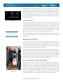
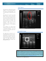
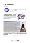
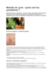
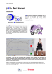
S W I N E S C A N NI NG L E S S O N N U M B E R 1
BioSoft Toolbox® for Swine
Scanning for Marbling
Scanning Swine for Marbling
The purpose of this lesson is to describe proper procedures for ultrasound scanning of
Inside This Lesson
live swine to determine the amount of marbling in the pork loin muscle. The scientific
anatomical name for this muscle is longissimus dorsi. Marbling can also be referred to
as intramuscular fat (IMF) and is reported in the units of a weight percentage. A
1
Scanning Equipment
2
Age to Scan
2
Restraining the Pig
2
Scanning Site and Preparation
4
Aligning the Transducer
4
Freezing the Image
5
IMF Image Landmarks
the images that are captured for each pig. The capturing of quality images requires
6
Region of Interest
a significant amount of practice by the ultrasound technician.
7
Problem Images
marbling score of 3 means that the muscle tissue of the longissimus dorsi has a total
lipid percentage amount of 3% of the weight as compared to the total tissue sample
weight.
Texture analysis of B-mode ultrasound images taken on live swine is used to
determine the amount of marbling or IMF in the loin muscle tissue. Software has
been developed by Biotronics to perform this texture analysis on these images. For
the most accurate determination of IMF, proper procedures and scanning protocol
must be adhered to. The IMF estimation results will only be as good as the quality of
Scanning Equipment
The BioSoft Toolbox® for Swine works with images captured with the Aloka SSD 500V
Equipment settings must
be checked before the
start of each scanning
session.
ultrasound scanner and when using the UST 5011 3.5 MHz linear array transducer. This
software will not work with any other ultrasound scanner configuration. Biotronics,
Inc. is working on software that will work with other scanner brands, and that
technology will be released when available.
Sophisticated texture analysis procedures are used to estimate the IMF amount in
the loin muscle, so it is absolutely necessary that several equipment settings be
made on the ultrasound scanner prior to scanning. The ultrasound technician must
make sure that the settings are correct before each scanning session. It is also
important to make sure that during the scanning session, settings are not
accidentally changed.
OVERALL gain (G), controlled by the large circular knob on the console left front
face is to be set to G90 or its maximum value as shown in Figure 1. The slider controls
located just above the overall gain knob control NEAR gain (N) and FAR gain (F).
The NEAR gain is to be set to N-25, and the FAR gain is to be set to F2.1. These values
appear on the console CRT display in the lower left corner as shown in Figure 2.
Figure 1. Gain controls.
This publication was developed by
Biotronics, Inc. and has been reviewed for
its correctness by Clint Schwab, PHD,
Director of Commercial Services, National
Swine Registry, P.O. Box 2417
West Lafayette, IN USA 47996
©2008 Biotronics, Inc. All Rights Reserved.
Copies Available From:
Biotronics, Inc.
1606 Golden Aspen Drive, Suite 104
Ames, Iowa USA 50010-8011
[email protected]
(515)-233-4161
PAGE 2
LESSON: SCANNING FOR MARBLING
Magnification of the image size must be set to X1.5. This setting is controlled by a
button on the front face of the console. The ultrasound scanner can be checked to
make sure the magnification is correct by looking on the CRT display lower left hand
corner (see Figure 2). Focus zones 1 and 2 must be enabled, with zones 3 and 4 in
the ‘off’ position. Frame correlation is to be set to ‘auto’; contrast to ‘4’; and AGC to
‘1’. Refer to the Aloka SDD 500V User’s Manual for more information on properly
setting the equipment.
Figure 2. Gain and magnification
settings.
Age to Scan
The IMF prediction software has been developed from images captured on pigs that
are at a market weight of 250-280 pounds (113.5-127 Kg). In the USA, pigs achieve
this weight by the time they are approximately six months old. At this age, most pigs
will have a loin depth that is sufficient for texture analysis to determine the IMF. Also,
at this weight and age, pigs will have expressed their individual genetic potential for
IMF.
Quality images can
only be captured from
properly restrained pigs.
There are no assurances that the software will work for pigs that are not
generally of the six month age and at the weight range given above.
The BioSoft Toolbox® for Swine will work equally well for barrows, gilts and young
boars in the determination of IMF. This software can be used with all swine breeds
and crosses.
Restraining the Pig
Quality ultrasound images can only be captured from pigs that are properly
restrained. The pig must be confined to a crate that will restrict its forward, rearward,
and lateral movement. The pig must be also be restrained so that it is not able to
raise its head above the top of the crate or to climb out of the crate. Quality images
can only be captured when the pig is near motionless.
Some technicians have developed a mechanical bar that goes between the legs of
the animal (from front to back) and can be raised to elevate the pig off of its feet.
An example crate with a raising bar that was developed by swine researchers in
Canada is shown in Figure 3. This is an extremely useful innovation that contributes
not only to capturing excellent quality images, but to the safety of both the pig and
the technician. This innovation also cuts down considerably on the amount of time
required to scan the pig, and minimizes the stress level of the pig.
Scanning Site and Preparation
The region of scanning for IMF is directly behind the front shoulder of the pig, and at
approximately 5 cm off the midline. The pig can be scanned on either the left or
right side; however, it is important that all pigs within a contemporary group be
scanned on the same side.
the
Figure 3. Restraining crate for
scanning pigs.
13th
The region of scanning will extend over the 9 th through
ribs where the numbering starts at the anterior (forward) position. This entire
region needs to be cleaned thoroughly and free from any dirt or other debris. If the
pig has a very thick hair coat, it may be necessary to clip the hair so that the
ultrasound signal can be transmitted without excessive reflection or absorption.
©2008 Biotronics, Inc. All Rights Reserved.
LESSON: SCANNING FOR MARBLING
PAGE 3
Technicians may find it convenient to position the crate and a table for the
ultrasound equipment as shown in Figure 4.
This configuration allows the
technician to both observe the image that is being captured and the positioning
of the transducer on the back of the pig at the same time.
Figure 5 is the skeleton of a mature porcine that has 14 ribs with the most
posterior rib numbered as 14. The red colored bracket is located over the 12th
through the 9th ribs, and this is the position for placing the transducer for the IMF
image. The red line in Figure 6 is showing the similar position.
Figure 4. Scanning crate and
equipment setup.
14th rib
Figure 6. Position of the transducer for
the IMF image.
Figure 5. Skeleton of a mature porcine.
After cleaning the scanning site, a vegetable oil couplant must be liberally
applied to the skin surface. It may be necessary to reapply the couplant from
time to time during the scanning of each pig. Soybean oil makes a very good
type of couplant; however, other oils such as corn oil can be used effectively.
Acoustic gel is generally too expensive to be used as a scanning couplant for
animals. The couplant allows the ultrasound signals to easily go through the skin
and into the tissues below the skin surface. Air pockets between the transducer
and skin surface will reflect most of the ultrasound energy before it reaches the
skin.
Technicians may have their own preference for holding the transducer when
scanning for IMF, however, the method shown in Figure 7 allows a significant
amount of control. The transducer is cradled between the thumb and the index
finger, and grasped just behind the cord that exits the transducer on the top
side. Notice that the fingers are touching the skin of the animal and are used to
Figure 7. Hand position for holding the
transducer.
help steady the transducer as it is moved laterally at the top to reduce the
magnitude of echoes (if present in the image).
©2008 Biotronics, Inc. All Rights Reserved.
PAGE 4
LESSON: SCANNING FOR MARBLING
Aligning the Transducer
The ultrasound transducer is to be aligned parallel with the midline of the pig and
approximately 5 cm off the midline as shown in Figure 8. The transducer should also
be almost perpendicular to the skin surface. For smaller pigs, the transducer may
need to be placed closer to the midline at 4 cm and for large pigs further from the
midline.
The objective is to have the image (called a longitudinal image) captured at the
cross-sectional midpoint of the longissimus dorsi muscle as shown in Figure 9. It is
also important that the image shows the longitudinal image with a near maximum
loin muscle depth.
Artifacts of ultrasound that need to be minimized or eliminated are what are
referred to as echoes. Echoes are mirror reflections of tissue interfaces caused by
very strong signal returns. Echoes can be minimized by slightly tilting the transducer
Figure 8. Scanning for IMF.
so that it is not directly perpendicular to the surface of the skin. In some cases the
echoes can be completely removed from the image, while in other cases, they can
only be reduced.
Traditionally, the texture analysis for IMF is done within the region of the ultrasound
image that is between the 10th and 11th ribs of the animal (as counted from the
anterior end of the animal). This is the anatomical location at which the trapezius
muscle will be only slightly visible in the image.
Technicians are to use the trapezius muscle as an IMF image reference ‘landmark’.
The posterior end of the trapezius muscle lies above the 10th rib on most pigs,
making it a valuable reference point.
Without the tip of the trapezius muscle
appearing in the image, there is no way to be sure that the 10th rib can be correctly
identified as the rib tops all look alike. More discussion on this point is found in the
Figure 9. Scanning plane for the IMF
image.
Problem Images section.
Freezing the Image
A remote ‘freeze’ switch can be provided with the Aloka SSD 500V. This switch is
held by one hand of the scanning technician, and the transducer is held in the
other hand as shown in Figure 10. The technician will be watching the image on the
console CRT to determine when the transducer is in the correct location, and when
a quality image can be frozen by pressing the freeze switch. If the image is not of
good quality, then the image is released by pressing the freeze switch a second
time. Images that are not of high quality should never be captured by the BioSoft
Toolbox® software.
Evidence of a poor quality image include, but is not limited to the following: (1) the
appearance of a blurring of the image, (2) poor contact of the transducer on the
skin, (3) dark regions in the image, (4) bright echoes, and (5) electrical interference
as seen by periodic and repeating lines in the image that are non- anatomical
Figure 10. Transducer alignment and
freeze switch.
features.
©2008 Biotronics, Inc. All Rights Reserved.
LESSON: SCANNING FOR MARBLING
PAGE 5
IMF Image Landmarks
IMF image landmarks provide the technician with the information needed to judge
the quality of a frozen image. The skin and three fat layers will generally be easily
identified in the image. For pigs with external fat of less than 10 mm, the third fat
layer may not be distinguishable from the second fat layer
The image should display diagonal features or striations that are the individual
muscle fiber interface boundaries. These striations always move downward at a
diagonal slant and toward the head of the pig. For pigs with a large amount of
external fat, and for pigs that have high IMF levels, the striations will be less visible
than in a less fat pig or in one with a lower IMF level.
Five to 7 quality IMF
images must be
capture per pig for the
highest accuracy.
As shown in Figure 11, the tops of the ribs should be well defined in the image. The
intercostales muscles that anatomically attach the ribs together should appear
distinct and clear in the image.
The most posterior end of the trapezius muscle should be showing in the image. This
end will be used in defining the position of the 10th rib. As the technician drops an
imaginary line down from the trapezius end, the line will intersect or come very close
to the 10th rib.
The technician should capture between 5 and 7 quality images for each pig
scanned using the BioSoft Toolbox® for Swine capturing software. It is important to
capture more than one image for purposes of improving the accuracy of the IMF
determination. Through research, it has been found that 5 to 7 images will provide
the best opportunity for the highest accuracy. An IMF value will be determined for
each image within an animal, and then the individual image IMF values are
averaged across all of the images within that animal. The interpretation software
allows up to 10 images per pig. This should allow for an ample number of images if
some have to be ignored because of poor quality during the interpretation process.
Posterior end of the
trapezius muscle
Muscle striations
Rib tops
10th
11th
12th
Intercostales muscles
Figure 11. A high quality IMF image.
©2008 Biotronics, Inc. All Rights Reserved.
PAGE 6
LESSON: SCANNING FOR MARBLING
Region of Interest
Texture analysis is done within a user-positioned region of interest (ROI) for each IMF
image when using the BioSoft Toolbox® for Swine. The ROI is a square box that will
appear on top of the image when it is being interpreted. The objective of every
scanning session for IMF is to capture images that will allow proper ROI box
positioning and texture analysis.
The objective of every
scanning session is to
capture images that will
allow proper ROI
positioning and texture
analysis.
The ROI box is manually positioned by ‘dragging’ it with the computer mouse.
There are two sizes of ROI boxes that can be selected for use within the BioSoft
Toolbox® for Swine interpretation software.
The box that will maximize the ROI size without the box being positioned directly on
rib tops or over echoes should be selected. If this is not possible, the technician
should choose a smaller ROI box size.
The ROI position should normally be placed above and between the 10th and 11th
ribs. Deviations from this may be required because of dark regions that need to be
avoided or because the echoes are too prominent. The objective is to find the
‘best’ region and largest region that outlines a homogenous texture for analysis.
Sometimes there are bright ‘spots’ that will appear within the ROI. These can be
caused by sound reflections off of the rib tops that move upwards in the image
and that tend to magnify the intensity of the muscle striations. These bright spots
should be avoided if possible.
The longitudinal image shown in Figure 12
has a region of interest (ROI) box that has
been
manually
computer
positioned
mouse.
This
ROI
with
box
a
is
positioned almost directly between the
10th and 11th ribs. There is just a very small
tip of the posterior end of the trapezius
muscle showing in this image.
The ROI
does not include any rib tops.
The ROI is also located below the artifact
echoes appearing in this image. It can be
seen that the texture of the image within
the
boundaries
of
the
ROI
box
is
homogeneous.
Images captured for determination of IMF
must be of the quality shown in Figure 12.
It is to be noted that this image should
have been improved by the technician by
minimizing the echoes.
However, the
echoes do not intersect the ROI, and
Figure 12. IMF image with region of interest (ROI).
therefore, they will not affect the accuracy
of the IMF determination.
©2008 Biotronics, Inc. All Rights Reserved.
LESSON: SCANNING FOR MARBLING
PAGE 7
Problem Images
Images that exhibit problems are going to reduce the accuracy of IMF
determination for the pig. Examples of common problems are shown in the following
pictures. For most cases, images with these problems should not be used in the
determination of IMF. An understanding of the anatomy of the pig is required before
a technician can repeatably capture quality IMF images.
Many problem images
can be avoided if the
anatomy of the pig is
understood.
Trapezius muscle
Images that have been captured with incorrect equipment settings are to be
discarded and not used in the determination of IMF.
Too Much Trapezius Muscle
Figure 13. Cross-sectional picture at the
5th rib (photo courtesy of Clint Schwab).
Spinalis dorsi muscle
The image shown in Figure 14 is taken
too far forward on the animal.
This is
evidenced by the amount of trapezius
muscle and the spinalis dorsi muscle that
are shown in the image.
A properly collected IMF image will not
contain any of the spinalis dorsi muscle
and will contain only the posterior tip of
the trapezius muscle.
The box shown in the image contains
the
posterior
end
of
the
trapezius
muscle.
8th Rib
Figure 14. Image with too much trapezius muscle.
©2008 Biotronics, Inc. All Rights Reserved.
PAGE 8
LESSON: SCANNING FOR MARBLING
Correct Amount of Trapezius Muscle
Trapezius muscle
10th rib top
The image shown in Figure 15 is a
properly captured IMF image. Just the
posterior end of the trapezius muscle is
showing. It can be seen that the 10th rib
is almost directly below this posterior
end. The ROI for interpretation of IMF is
placed between the 10th and over the
top of the 11th rib.
The ROI is always positioned so that it
does not contain rib tops, fat layers or
echoes.
It is important for the texture
within the ROI to appear consistent and
homogeneous.
Figure 15. Image showing the correct amount of trapezius muscle.
Acceptable Image
The image shown in Figure 16 is an
acceptable image. Just the tip of the
posterior end of the trapezius muscle is
shown in the image.
There are no
echoes appearing in the longissimus
dorsi (loin muscle) part of this image.
This is a relatively fat pig, with a narrow
loin depth.
This image will require a
smaller ROI than the image shown in
Figure 15.
changed
The size of the ROI can be
during
the
image
interpretation process.
Note the consistent texture that appears
within ROI.
Figure 16. Acceptable Image.
©2008 Biotronics, Inc. All Rights Reserved.
LESSON: SCANNING FOR MARBLING
PAGE 9
Poor Contact
Poor contact
The image shown in Figure 17 has
several problems.
A major problem is
that there is not good contact between
the ultrasound transducer and the skin
of the pig.
It could be that the pig moved at the
instant the freeze switch was depressed.
It is also possible that there was not
enough couplant applied to the skin of
the pig. Images that look like this should
not be interpreted for IMF.
This image also has the appearance of
being
blurred.
intercostales
The
muscles
rib
tops
and
are
not
well
defined. This image should not be used
to determine IMF.
Figure 17. Image with poor contact.
Acceptable Image
The image shown in Figure 18 is of
acceptable quality to predict IMF. The
posterior tip of the trapezius muscle is
easily identified, and there are no
echoes in the location where the ROI is
positioned.
Figure 18. Acceptable image.
©2008 Biotronics, Inc. All Rights Reserved.
PAGE 10
LESSON: SCANNING FOR MARBLING
Blurred image
The image shown in Figure 19 is what is
referred to as a blurred image.
An
unblurred image taken on the same pig
is shown in Figure 20. Sometimes blurring
is very subtle, and only the experienced
eye can determine that an image is
blurred.
Having an unblurred image on the same
animal makes the determination much
easier. In this case, one can see that
the image in Figure 20 is much more
crisp and sharp than the image shown in
Figure 19.
Blurring occurs when there is movement
of the transducer at the same time the
image is frozen. This can be cause by
movement of the pig, or because the
technician moved the transducer at the
Figure 19. Blurred image.
instant the freeze switch was pressed.
Blurred
images
should
never
be
interpreted for IMF as the result will not
be accurate.
It is to be noted that there is no trapezius
Image without Blurring
posterior end showing in the image of
Figure 20. So even though the image is
not blurred, it is not a good image
because without the
trapezius end
showing, it is impossible to determine
which is the 10th rib. It is suspected that
this image is collected too posterior on
the animal, and the transducer is over
the 14th, 13th and 12th ribs (the 14th rib
being the left-most rib).
There are echoes appearing in the
image in Figure 20, however, the loin
depth is sufficient for position of the ROI
without any problems.
Note the direction of the diagonal
muscle striations.
They are going from
left to right in the image meaning that
the head of the pig is to the right of this
image. The technician has reversed the
direction of the probe to capture these
images (see the red circle).
Figure 20. Image without blurring.
©2008 Biotronics, Inc. All Rights Reserved.
LESSON: SCANNING FOR MARBLING
PAGE 11
Echoes and Noise Interference
The image shown in Figure 21 has
echoes within the region where the ROI
should be placed.
caused
by
The echoes are
the
strong
interface
reflections between the fat layers.
Echoes can be minimized by slightly
tilting the transducer on the surface of
the skin and so that the alignment is not
directly perpendicular.
This image is also showing some type of
signal
interference
or
noise
streaks.
These streaks can be seen in the dark
regions and in the shadow of the rib
tops. Some of the streaks are circled in
red. Images with interference should not
be interpreted for IMF.
This image is also missing the tip of the
trapezius muscle.
Figure 21. Image with echoes and interference or noise.
Acceptable Image
The image shown in Figure 22 is an
acceptable image. The posterior end of
the trapezius muscle is showing in the
image. The rib tops are clearly defined
along with the intercostales muscles.
The scanning technician should use the
image shown in Figure 22 as their
ultimate image quality objective. With a
set of images like this for every pig, the
accuracy of IMF prediction will be
10th
11th
12th
enhanced.
Figure 22. Acceptable image.
©2008 Biotronics, Inc. All Rights Reserved.
PAGE 12
LESSON: SCANNING FOR MARBLING
Poor Rib Top and Intercostales Definition
The image shown in Figure 23 has
several problems.
It has two dark
regions, indicating that there was not
sufficient
couplant
between
the
transducer lens and the skin of the
animal.
The rib tops and intercostales muscles
are not well defined in this image. There
is no evidence of the trapezius muscle,
and
the
technician
should
have
minimized the echoes.
This image should not be used to
determine an IMF value.
Figure 23. Image with poorly defined rib tops and intercostales muscles.
Acceptable Image
The image shown in Figure 24 is an
acceptable image and can be used to
determine IMF. There is some evidence
of echoes in this image, so a small ROI
should be used so that the echoes do
not intersect or appear within the ROI.
The posterior end of the trapezius muscle
is present in this image. The rib tops and
intercostales muscles are well defined.
Figure 24. Acceptable image.
©2008 Biotronics, Inc. All Rights Reserved.
LESSON: SCANNING FOR MARBLING
PAGE 13
Dark Regions
The image shown in Figure 25 has several
problems. One of the major problems is
that there are several dark regions. One
of the dark regions is outlined with the red
oval.
Dark regions can be caused by several
different things.
Usually, it means that
there is not enough couplant between
the transducer lens and the skin of the
animal. It could also mean that the skin is
dirty and needs to be cleaned.
Two
other reasons include that one or more
transducer
crystals
may
not
be
functioning or that excessive hair is
causing attenuation of the ultrasound
signal.
Other problems in this image include
excessive echoes and some type of noise
or electrical interference.
Also, the
Figure 25. Image with dark regions.
posterior tip of the trapezius muscle is not
showing in the image.
Acceptable Image
The image shown in Figure 26 is an
acceptable image and can be used to
determine IMF. The posterior end of the
trapezius muscle is present. The rib tops
and the intercostales muscles are clearly
defined.
The region where the ROI is
placed contains a very consistent and
homogeneous texture.
Figure 26. Acceptable image.
The BioSoft Toolbox® for Swine is a revolutionary set of software programs allowing swine
breeders to capitalize on the opportunity of improving compositional and quality traits
with the noninvasive attributes of ultrasound. These programs are state-of-the-art with
the latest in technology and advanced texture analysis processing. The development
has been accomplished by animal scientists and engineers with more than 60 years
combined research and development experience in ultrasound technology. For more
information, contact Biotronics, Inc. at [email protected].
©2008 Biotronics, Inc. All Rights Reserved.