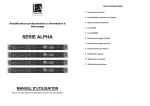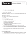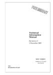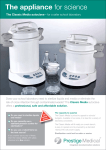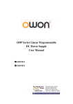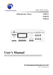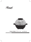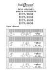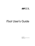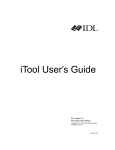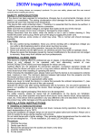
1
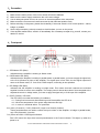
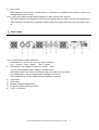
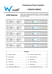
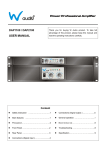
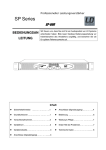
Professional Power Amplifier
SP Series
SP-600
USER MANUAL
Thank you for buying LD-Systems Audio product. To take full
advantage of this product, please keep this manual and read the
operating instructions carefully.
Content
z
Safety instruction….…...……………………..1
z
Connections (Signal output ) ..……….…..5
z
Main features….....……….…………………..1
z
General operation. ………………….….....6
z
Precaution…………………………………….1
z
Maintenance……………………………7
z
Front Panel ………..….…..………………….2
z
Troubleshooting. ……………….………….8
z
Rear Panels………….……………………….3
z
Specification.………………………….........9
z
Connections (Signal input )………...............4
1. Safety Instructions
The lighting flash with arrowhead symbol, within an equilateral triangle, is intended to alert the user
to the presence of uninsulated “dangerous voltage “within the product’s enclosure that may be of sufficient
magnitude to constitute a risk to persons.
The exclamation point, within an equilateral triangle, is intended to alert the user to the presence of
important operating and maintenance (servicing) instructions in the literature accompanying the appliance.
1.) Caution: Avoid the risk of electric shock, do not remove the cover. No user serviceable parts inside.
2.) To prevent fire or shock hazard, do not expose the unit to rain or moisture. Do not place metal objects or
spill liquid inside the unit; electric shock or malfunction may result.
3.) Don’t cover any ventilation slots as this may result in overheating. Always install the unit in a well
ventilated place. Avoid presence of heat sources, and avoid dusty and humid environments.
4.) Do not repair the unit by yourself. Checks or repairs of the unit must be made by qualified personnel only.
2.Main features
Professional power amplifiers with advanced switch mode power supply technology for higher performance.
Perfect for Public address. discotheques, clubs, theatres, etc.
The amplifiers feature:
z Soft start up
z Automatic voltage/ current limiter
z Short circuit protection
z DC fault protection
z High temperature protection
z Overloaded protection
z Selectable operation modes : Stereo, bridge & parallel
z Neutrik Combo Input connector and Speakon output connector.
z Power, Protect, Limit, Signal, Stereo, BTL (Bridge), & PAR (parallel) indicators.
SP 600 PROFESSIONAL POWER AMPLIFIER USER MANUAL PAGE
1
V-
3.Precaution
1)
2)
3)
4)
5)
6)
7)
Make sure the mains power of the unit is turned off before installation.
Make sure the mains supply matches to the unit’s rated voltage.
Use an adequate power source; do not turn on several amplifiers at the same time.
Make sure all the connectors are well connected in their indicated position firmly.
Before switching on the power, please check carefully if the mode switch is in its correct position – stereo,
bridge, or parallel.
Set the input sensitivity (volume) controls to the left before you turn on the power.
If the amplifier malfunctions, switch it off immediately. Do not attempt to repair it by yourself, contact your
dealer for service.
4.Front panel
1)STR/Stereo LED (Blue)
Indicates that the amplifier is working in Stereo mode.
2)PAR/Parallel LED (Blue)
Indicates that the amplifier is working in parallel mode. In parallel mode, you have to apply the signal only
to the CHA (Channel A) input of the amplifier. The signal input is from CHA, but the signal outputs are
same as in Stereo mode, i.e. from CHA & CHB outputs, connecting to two speakers.
3)BTL/Bridge LED (Blue)
Indicates that the amplifier is working in bridge mode. This means that both channels are switched
together in series to act as mono amplifier. The output power is almost three time of that compared to the
separate channels. In bridge mode, you have to apply the signal only to CHA input of the amplifier.
4)PROT (Protect) / YELLOW
The LED will be on under the following 3 conditions:
4-1)During first few seconds after switching on/off the amplifier the LED is on.
4-2)When the temperature of the power stage becomes too high.
4-3)In case of a technical defect : DC protection.
5/6.) CHA ( Channel A ) / CHB ( Channel B ) Input Level Control (Volume)
These potentiometers are used to control the input volume of the amplifier. In bridge or parallel mode,
only CHA (Channel A ) is active.
7/8.) Power and CHA / CHB Signal indicators:
First LED around the input level control potentiometer is the Power indicator. This lights up when the
power is on.
SP 600 PROFESSIONAL POWER AMPLIFIER USER MANUAL PAGE
2
V-
9)Power switch
When switching on the power, it takes about 3~ 4 seconds to complete the soft start-up function, the
amplifier is then ready to work.
10/11) LIMIT LED: When the input signal voltage is too high, the limit LED will be on.
The limiter reduces the average input level when the signal begins to distort; this process is designed to
reduce distortion and protect the speakers. Please reduce the signal input level when the LIMIT LED is
on.
5.Rear Panels
1/2. ) CHA/CHB input Combo connectors :
Combination of 3-pin XLR & 6.35 (1/4”) JACK connectors.
Pin 1:Ground / Pin 2:Signal + / Pin 3:Signal 3) Mode Switch: The amplifier is shipped in “ Stereo “ mode.
You can select between Stereo, Bridge, or Parallel mode.
STR/ Stereo Mode: You have to connect the input and output of both channels.
BTL/ Bridge Mode: The input signal must be applied to CH A only.
PAR/ Parallel Mode: The input signal must be applied to CH A only.
4) CHA output
5) CHB output
6) Speakon Output for bridge mode
7) AC power cord for mains power input
8) FUSE:F10A/250V
SP 600 PROFESSIONAL POWER AMPLIFIER USER MANUAL PAGE
3
V-
6.Connections (Signal Input)
1)Unbalanced wiring:
Photo 1- Signal input using a 1/4” mono Jack
CHA & CHB signal input:
Use a mono jack- Tip = signal
Sleeve= ground
Photo(1)
For balanced wiring, you can also use a 1/4” Stereo Jack.
2)Balanced wiring:
Photo 2 – Signal input using an XLR connector
CHA & CHB Signal input:
Pin1= Ground
Pin 2= Signal +
Pin 3= Signal –
Photo(2)
Note:Incorrect connection will result in malfunction. Make sure the connection is correct before operation.
SP 600 PROFESSIONAL POWER AMPLIFIER USER MANUAL PAGE
4
V-
7.Connection(Signal output)
1)Stereo Mode
Photo 4- Signal output using Speakon connector
CHA & CHB signal output:
1+、2+ Signal output (+) connect to speaker (+)
1-、2- Signal output (-) connect to speaker (-)
Photo(4)
2)Bridge mode
Photo 5- Signal output using Speakon connector
Be sure to set the mode switch on the rear panel to “ bridge “ ( BTL ).
1+、2+ Signal output (+) connect to speaker (+)
1-、2- Signal output (-) connect to speaker (-)
Photo(5)
SP 600 PROFESSIONAL POWER AMPLIFIER USER MANUAL PAGE
5
V-
3)Parallel Mode
Photo 6- Signal output using Speakon connector
1+、2+ Signal output (+) connect to speaker (+)
1-、2- Signal output (-) connect to speaker (-)
Signal input from CHA, signal output from CHA & CHB.
Photo(6)
Note:Incorrect connection will result in malfunction. Make sure the connection & operation mode is correct
before switching the power on.
8.General Operation
1、Operation procedures:
1) Connect to the matching speakers
2) Make sure all the input & output connections are correct and well connected
3) Make sure the mains power supply matches to the power indicated on the amplifier.
4) Connect the signal source equipment, eg : Mixer, to the amplifier’s signal input
5) Set amplifier’s input level (volume) to the minimum
6) Set the mode switch to the required operation mode ( stereo, bridge, or parallel ).
7) Turn on the power of signal source equipment first (mixer etc…), then the amplifier
8) Adjust the input level (volume) to the intensity you want.
2、Operation procedure of Bridge, Parallel & Stereo mode:
A.) Stereo Mode:
a.) Ensure the amplifier is switched off
b.) Connect speakers to CHA and CHB outputs
c.) Set mode switch to “stereo “
d.) Input signal device to CHA and CHB inputs
e.) Turn on the power of amplifier
f.) Adjust CHA and CHB signal volume
Caution: The amplifier will protect itself if it is used continuously under 2 Ohm stereo at its maximum for long
SP 600 PROFESSIONAL POWER AMPLIFIER USER MANUAL PAGE
6
V-
durations.
B.) Bridge mode:
a.) Ensure the amplifier is switched off
b.) Connect speaker to “ bridge “ speakon output.
c.) Set mode switch to BTL ( bridge ).
d.) Input signal device to CHA input
e.) Turn on the power of amplifier
f.) Adjust CHA signal volume.
Caution: The amplifier will protect itself if it is used continuously under 4 Ohm bridge for long durations.
C.) Parallel mode:
a.) Ensure the amplifier is switched off
b.) Connect speakers to CHA and CHB outputs (as is stereo mode)
c.) Set mode switch to PAR ( Parallel)
d.) Input signal device to CHA input
e.) Turn on the power of amplifier
f.) Adjust CHA input volume control only for the output volume of CHA & CHB.
Caution: The amplifier will protect itself if it is used continuously under 2 Ohm parallel for long durations.
9.Maintenance
1. Clean the unit by wiping with a slightly damp cloth. Avoid getting water inside the unit. Do not use alcohol
or any volatile liquid that will damage the unit.
2. Clean the ventilation slots regularly with a vacuum cleaner. This increases the cooling capacity of the
amplifiers fans and helps preventing temperature overheat.
SP 600 PROFESSIONAL POWER AMPLIFIER USER MANUAL PAGE
7
V-
10.Troubleshooting
You can check some operation problems as mentioned below first before asking for help.
Problem
No response
when power on
No sound
Inadequate
output volume
Problem cause(s)
Suggested remedy
1、 Power did not turn on
1、 Turn on the power.
2、 Loose connection of the power cord
2、 Make sure the power cord is connected
firmly to the mains supply before turning on
the power of amplifier.
3、 blown fuse
3、 Turn off the power, then check the fuse on
the rear panel. Replace the fuse with same
type only if the fuse is blown.
1、 No signal input
1、 Connect the signal source equipment to
the amplifier, then turn on the power.
2、 Loose connection of the speaker or
damaged speaker
2、 Make sure the speaker is well connected.
Check if the speaker is in good condition.
3、 Wrong connection
3、 Make sure the connection between
amplifier and speaker is correct. Please
refer to the point 8 Connection ( signal
output ) for more information.
4、 Thermal protection
4、 Avoid overloading the amplifier for a long
time, or working in a badly ventilated area.
Check if the fans work properly and the
ventilation slots are clear of dust.
1、The signal input level (ivolume) is set
at minimum
1 、 Adjust the signal input level to the
appropriate intensity
2 、 Low output of the signal source
equipment ( CD player )
2、a. Increase the output of the signal source
equipment
b. Adjust the input sensitivity of
the amplifier.
SP 600 PROFESSIONAL POWER AMPLIFIER USER MANUAL PAGE
8
V-
11.Specification
Model No.
Output Power
1KHZ
THD+N≤0.1%
SP-600
Stereo 8Ω
300W x 2
Stereo 4Ω
550W x 2
Stereo 2Ω
850W x 2
Bridge 8Ω
1000W
Bridge 4Ω *
1400W
Parallel 8Ω
270W x 2
Parallel 4Ω
520W x 2
Parallel2Ω *
700W x 2
Frequency Response
20Hz~20KHz±0.5dB
Input Sensitivity
0.775V/1.0V/1.44V
S/N ratio (A Weighted RMS)
>100dB
Crosstalk at rated power output
(8Ω1KHz)
>85dB
Damping Factor (f=1kHz 8Ω)
>200
Protection
Soft start up, Thermal cut off、Short Circuit、Overloaded、
DC fault、Voltage limiter, AC line fuse
Indicators
Power、Signal、Protect、Limit、Stereo、Bridge、Parallel
Connectors
INPUT: NEUTRIK COMBO x 2; XLR Link male x 2; OUTPUT:
NEUTRIK Speakon x 3
Cooling system
Low noise, variable speed fans
Power supply
230V ~ 50Hz
Dimension(W×D×H)/Weight
483 x 499 x 44 mm
10,3kg
* Important note: We do not recommend a 2 Ohms stereo or a 4 Ohms bridge mode operation under
full load conditions!
Warranty
Adam Hall warrants its products to be free of all detectable flaws in material and workmanship for a period of
24 (twenty-four) months from the date of sale. Any and all damage caused by misuse or improper use shall
be excluded from warranty. Tampering by outside parties or unauthorized modifications shall render any and
all warranties null and void.
SP 600 PROFESSIONAL POWER AMPLIFIER USER MANUAL PAGE
9
V-
Specification is subject to change without prior notice.
SP 600 PROFESSIONAL POWER AMPLIFIER USER MANUAL PAGE
10
V-