1
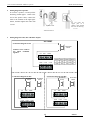
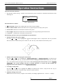
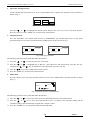
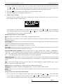
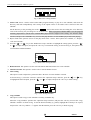
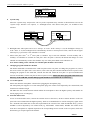
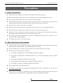
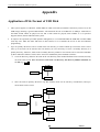
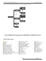
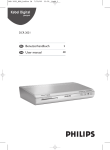
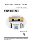
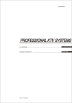
Public Address System Multi-function Player PM8712 PM8735 PM8745 User’s Manual Thank you for using our Public Address System. Please carefully read this manual first for better use. LY International Electronics Co., Ltd. http: //www.lyintlcorp.com * Fire Protection/Public Address System Multi-function Player Contents Installation Precautions ......................................................................................................... 2 Features................................................................................................................................. 2 Front Panel............................................................................................................................ 3 Rear Panel............................................................................................................................. 4 Wiring of Power Amplifier .................................................................................................... 5 Operation Instructions – Operation and Status Interface ........................................................ 7 Precautions............................................................................................................................ 12 1. Safety Precautions ................................................................................................. 12 2. After-sales Service Precaution ............................................................................... 12 Specifications........................................................................................................................ 13 Appendix .............................................................................................................................. 14 Application of File Format of USB Disk ............................................................................... 14 List of Built-in Programs in USB Disk .................................................................................. 14 1 PM8735 * Fire Protection/Public Address System Multi-function Player Installation Precautions Do not cover the vents. 1. Do not use the system in case of damage to the power cord. 3. The power socket shall be compatible with the power plug. 4. Do not use the power amplifier in a poorly ventilated, dusty or wet place, nor expose it to direct sunlight. Always keep away from heat source. Never apply vibration to the power amplifier. Features Public address system with built-in MP3 player, radio, timer, zone controller and pager. Runs programs by control of timer and has graphic interface with multi-level menus. Built-in MP3 player and tuner. FM/AM tuner with up to storable 40 radio stations. Selectable internal 1GB memory and external USB disk for MP3 player. With double USB interfaces, supports .MP3 files stored in a common USB disk, MP3 player, mobile HDD, card reader, etc. 3 channels of LINE IN, 3 channels of MIC IN and 1 channel of LINE OUT. Mute function available for MIC 1 and LINE 1 facilitates playing by priority. Uniform treble and bass control for all channels and independent volume control for individual channel. Timer-controlled program for one-week operation, up to 100 time schedules programmable for each day, and time schedules and programs that will not be lost in case of power failure. Two sets of timing plan, each of which can be edited for 7 days, and up to 100 time schedules for each day. 1 channel of AC220V timer-controlled output power socket and one short output interface controlled by timer control. Timer-controlled built-in MP3 or tuner programs can be played according to time schedules that are cycled by week. The starting time of a time schedule is accurate to a second. Power amplifier P1 output as well as 70V and 100V fixed-voltage output. 6-zone outputs enable switching on or off 6 zones according to the time schedule, of which voltage output is 100V. LCD with automatic backlight. 5 LED output level indicators. Just one device offers all functions of a complete set of public address system. 2 PM8735 * Fire Protection/Public Address System Multi-function Player Front Panel 8 1 1 9 2 10 11 12 13 14 15 16 3 4 5 9 USB interface On/Off switch Turn the switch to the “I” position to switch on the power, or turn the switch to the “o” position to switch off the power. 2 3 6 7 17 18 19 20 21 22 The USB interface is used as program source interface for MP3 player, and supports storage devices, such as common USB disks and mobile HDDs. Power indicator The indicator is turned on when the power is turned on, and turned off when the power is turned off. 10 LCD 6-zone manual switch 11 Selection key shown on main interface The LCD shows the status of function operation. A zone is controlled by the corresponding key which is touched to turn on or off the zone. The on/off status is shown on the bottom of LCD. Press the selection key under any menu, and the main interface as shown below will appear. Sat 08:35:00 4 Play/Pause/Radio Mute key Power supply: Off 1 off External MP3 player mode key Built-in MP3 player mode key 4 on 5 on 6 off 13 Ok key Press this key to confirm the current operation or access the menu of lower level. Also, press the key under the main interface to manually turn on/off the timer power or operate the program control. Radio mode and band key Press this key in any menu interface to switch to radio mode, and switch between FM and AM bands in radio mode. 8 2 off 3 off Setup Press this key to move the cursor leftwards to the desired option for selection. Press this key to switch to built-in MP3 player in any menu interface. 7 Program control start 12 Move key for option operation Press this key to switch to external MP3 player in any menu interface. 6 Source: Built-in Audio Current time: Tue 08:00: This key is used to play or make a pause in MP3 player mode, and is used to mute in radio mode. 5 23 14 Number increase or adjustment key Press this key to increase the number for operation concerning number adjustment, e.g. press the key to increase the frequency in radio mode, to select the next program in MP3 mode, or to select one of options under certain status. 5 LED output level indicators The 5 LED indicators indicate the size of output levels from the power amplifier. If the 5th indicator is turned on, overload exists and corresponding adjustment should be performed. Turn the volume knob to flash the 4th and 5th indicators. 3 PM8735 * Fire Protection/Public Address System Multi-function Player 20 AUX3/MIC3 IN volume adjustment knob 15 Move key for option operation This knob is used to adjust the volume of LINE IN 3 and MIC 3. The signal adjusted is determined by selector switch on the rear panel. If the switch is turned to the AUX3 position, the volume of LINE 3 can be adjusted; if the switch is turned to the MIC3 position, the volume of MIC 3 can be adjusted. Press this key to move the cursor rightwards to the desired option for selection. 16 Number reduction or adjustment key Press this key to increase the number for operation concerning number adjustment, e.g. press the key to increase the frequency in radio mode, to select the previous program in MP3 mode, or to select one of options under certain status. 21 AUX2/MIC2 IN volume adjustment knob This knob is used to adjust the volume of LINE IN 2 and MIC 2. The signal adjusted is determined by selector switch on the rear panel. If the switch is turned to the AUX2 position, the volume of LINE 2 can be adjusted; if the switch is turned to the MIC2 position, the volume of MIC 2 can be adjusted. 17 Bass knob This knob is used to adjust the bass, which is turned clockwise or counterclockwise to increase or reduce the bass. 18 Treble knob 22 AUX1/MIC1 IN volume adjustment knob This knob is used to adjust the treble, which is turned clockwise or counterclockwise to increase or reduce the treble. This knob is used to adjust the volume of LINE IN 1 and MIC 1. The signal adjusted is determined by selector switch on the rear panel. If the switch is turned to the AUX1 position, the volume of LINE 1 can be adjusted; if the switch is turned to the MIC1 position, the volume of MIC 1 can be adjusted. 19 MP3/Radio volume knob This knob is used to adjust the volume of MP3/radio. When the volume is turned off, no sound is output in MP3/Radio mode. 23 MIC 1 interface Rear Panel 2 3 1 1 18 17 2 Power amplifier output COM terminal 4 16 15 14 13 5 6 12 11 10 7 9 8 Power amplifier output HOT terminal For details about the amplifier output HOT terminal, refer to the following text. Fixed amplifier output resistance, 70V, 100V and 6-zone COM terminals. 4 PM8735 * Fire Protection/Public Address System Multi-function Player 3 FM antenna Connects an FM antenna. 4 AM antenna Connects an AM antenna. Please note the ground terminal when connecting. 5 Short OUT interface The short OUT interface is used to provide short-circuit signal to devices requiring short-circuit signal. The short-circuit signal is controlled by the timer power supply. 6 Timer power output socket This socket offers an AC220V voltage to other device, which is controlled manually or by time schedule. 7 Timer power supply fuse In case of fuse blowing, please replace the fuse with a new one with the same specifications. If this failure still exists, please check the circuit for failure. 8 AC220V output power fuse In case of fuse blowing, please replace the fuse with a new one with the same specifications. If this failure still exists, please check the circuit for failure. 9 AC220V power socket The power socket is used to connect to the mains for power supply of the system. 10 AUX1/MIC1 IN selector switch The AUX1 and MIC1 use a common input channel. If the switch is turned to the AUX position, the line signal is input; if the switch is turned to the MIC position, the microphone signal is input. 11 12 13 14 15 16 17 18 If signals from line and microphone are input to one channel at the same time, select the selector switch to adjust the volume of one of the signals. AUX OUT interface This interface is used to connect to an audio monitor, such as a power amplifier. AUX1 IN interface This interface is used to connect to an audio source, such as a CD player, tuner and cassette. MIC2 IN interface AUX2/MIC2 IN selector switch The AUX2 and MIC2 use a common input channel. If the switch is turned to the AUX position, the line signal is input; if the switch is turned to the MIC position, the microphone signal is input. AUX2 IN interface This interface is used to connect to an audio source, such as a CD player, tuner and cassette. AUX3 IN interface This interface is used to connect to an audio source, such as a CD player, tuner and cassette. MIC3 IN interface AUX3/MIC3 IN selector switch The AUX3 and MIC3 use a common input channel. If the switch is turned to the AUX position, the line signal is input; if the switch is turned to the MIC position, the microphone signal is input. Wiring of Power Amplifier 1 Wiring diagram of zone output The output voltage of each zone is 100V. To connect the zone output, refer to the right diagram and note that the HOT and COM terminals are different. Speakers connected to zones should be provided with transformer. Zone 1 Zone 6 Speaker with transformer Speaker with transformer SP1 SP2 SP3 Caution: Make sure that the power supply is turned off when wiring. COM 5 COM SP4 SP5 SP6 COM COM COM COM PM8735 * Fire Protection/Public Address System 2 Multi-function Player Wiring diagram of speaker To connect a speaker, cut and peel the insulating sheath approx. 15mm at the end of the speaker cable, connect the cable to the terminal as the right figure shown, and then tighten the cable with Do not place the copper part of a speaker cable behind the screw of cable lug. a screw. Speaker cable Actual connection 3 Wiring diagram of P1, 70V and 100V outputs SPEAKERS Connection diagram of P1: MATCHING TRANS Caution: Never connect two HOT terminals together. P1 70V 100V COM COM Connection diagram of 100V: Connection diagram of 70V: MATCHING TRANS MATCHING TRANS MATCHING TRANS COM MATCHING TRANS P1 70V 100V P1 70V 100V COM COM COM COM 6 COM COM PM8735 * Fire Protection/Public Address System Multi-function Player Operation Instructions Operation and Status Interface: 1. The interface as shown in Fig. 1, which is accessed after the system is turned on, is called the main interface in the following text. Sat 08:35:00 Source: Built-in Audio Current time: Tue 08:00: Power supply: Off 1 off Program control start 2 off 3 off 4 on 5 on Setup 6 off Fig. 1: Main interface The main interface contains: Sat 08:35:00: indicates the weekday and time of the next time schedule. Source: Built-in Audio: indicates the audio source of program played currently by the system. Current time: indicates the current date and time of the system. Power supply: indicates the on/off status of current timer power supply and program control status. “1 off 2 off…”: indicates the on/off status of current zone. The following operation can be performed under the main interface: Turning on/off the timer power supply Press the “ ” or “ ” key to highlight the “Off” box following the “Power”, and press the “Ok” key (as shown below) to turn on or off the timer power. In this case, the “Ok” key is the manual switch of timer power. Ok key Manual control operation of program control status Press the “ ” or “ ” key to highlight the “Program control start” or “Program control end” box following the “Power”, and press the “Ok” key (as shown above) to start or end program control status. In this case, the “Ok” key is the manual switch of program control status. Note: If the program control status is set to “Program control end”, the set time schedule will not be executed. Therefore, to execute the time schedule, the program control status should be set to “Program control start”. Accessing to Setup status Press the “ ” or “ ” key to highlight the “Setup” box following the “Power”, and press the “Ok” key (as shown above) to access the “Operation setup” interface as shown in Fig. 2. Manually turning on/off a zone Manual turn on or off a zone by using the zone on/off key accordingly right below the “1 off 2 of…f” display. 7 PM8735 * Fire Protection/Public Address System 2. Multi-function Player Operation of Setup interface A time schedule and system time can be set or a time schedule can be copied in the “Operation setup” interface as shown in Fig. 2. Operation setup Timer setting Time setting Copy schedule System setting Exit Fig. 2: Operation of Setup interface Press the “ ” or “ ” to highlight the desired option, and press the “Ok” key to access the Setup interface. Press the “Exit” key or the “MAIN” key to return to the main interface. 3. MP3 player mode Press the “EXT.MP3” (for external audio source) or “INNER.MP3” (for internal audio source) in any menu operation interface to access the operation interface of MP3 player mode as shown in Fig. 3. Play all EXT.MP3 mode Directory 03 \ Track 01 03: 17 Play all INNER.MP3 mode Director 02 04: 35 A thousand dreams of you \ Track 01 04:10 05: 20 Song of herding sheep Fig. 3 MP3 player interface The following operation can be performed under this interface: ① Press the “ ” or “ ② Press the “ ” or “ and press the “ ③ Press the “ ” to select the previous or next track. ” to highlight any of “Repeat”, “Select directory” and “Select track”, press the “Ok” key, ” or “ ” key for adjustment. After adjustment, press the “Ok” key. ” key to play an MP3 track or make a pause. ④ Press the “MAIN” key to return to the main interface. 4. Radio mode Press the “Radio” key in any menu operation interface to access the “AM/FM tuner” operation interface as shown in Fig. 4. AM/FM tuner Station 19 Band FM 100.45MHz Fig. 4 Operation interface of AM/FM tuner The following operation can be performed under this interface: ① Press the “ ” or “ ② Press the “ ” or “ ” to move the cursor upward or downwards and call a stored radio station. ” key to tune. Press and hold the key for 2 seconds to start automatic tuning, and the automatic tuning will be automatically stopped after a station is tuned. ③ Press the “AM/FM” key to switch between the AM and FM bands. 8 PM8735 * Fire Protection/Public Address System Multi-function Player ④ To store a radio station tuned, press the “Ok” key, and the station storage number shown will start flashing. Press the “ ” or “ ” key to move the cursor downwards or upwards to store the station to the storage number, and press the “Ok” key. In this case, the storage number stops flashing, and the station tuned is stored. ⑤ Press the “ ” key to mute the radio, and press it again to demute the radio. ⑥ Press the “MAIN” key to return to the main interface. 5. Edition of time schedule Select the “Set time schedule” option in the “Operation setup” interface, and press the “Ok” key to access the “Set time schedule” interface as shown in Fig. 5. No Sat Time 08 : 10 Only one audio source selectable Add Delete 001 : Power supply 35 TUNER On Zone setup Source setup Delete all Return Fig. 5: Timer setting interface The information of a time schedule can be edited in this interface. Press the “ ” or “ ” key to highlight the desired option, and press the “Ok” key. Press the “ ” or “ ” key to adjust the number or option. After setting a time schedule, press the “Ok” key to confirm setting. Required information for a time schedule: Sat: This option is the weekday of a time schedule, ranging from Mon to Sun. No: This option is the number of a time schedule, and the time schedule is arranged according to the numbers of time schedules of one day. Power supply: This option is used to edit the on/off status of the power output socket. The output power supply will turn on or off automatically when the time schedule is executed. Time: The starting time of a time schedule is accurate to a second. Zone setup: This option is used to set the on/off status of a zone when a time schedule is executed. The zone will turn on or off automatically when the time schedule is executed. Only one audio source selectable: Select the audio source in a time schedule from “TUNER”, “INNER.MP3”, “Stop” and “…”. The “TUNER” refers to the built-in tuner, the “INNER.MP3” refers to the built-in MP3 program, the “Stop” refers that the tuner or MP3 program played currently will be stopped when the time schedule is executed, and the “…” refers that the status before the time schedule is executed is maintained. Audio source setup: This option is used to set the program to be played when a time schedule is executed. Select a storage number of a radio station stored in the built-in tuner, or the number of program stored in the built-in MP3 player. Add: To edit a time schedule of the day, press the “Add” key to add a blank time schedule and then edit it, or press this key to add a time schedule after another. Delete: Deletes the highlighted time schedule in the time schedule edition interface. Delete all: Deletes all time schedules of the highlighted day in the time schedule edition interface. Return: This key is used to return to the “Operation options” interface. Press this key to return after the edition of a time schedule. Setting of audio source program of time schedule: ① To set program of time schedule for built-in MP3 audio source: press the “ ” or “ ” in the “MP3 timer setup” interface to highlight the setting option, press the “ ” or “ ” to adjust the option, and press the “Ok” key to confirm the setting. As shown in Fig. 7, the option to be set has 3 tracks and repeat modes. 9 PM8735 * Fire Protection/Public Address System Multi-function Player Built-in MP3 timer setting Please select the directory and number of a track. 1 05 \ 12 Repeat 2 00 \ 06 Repeat 3 07 \ 01 Ok Fig. 7: MP3 timer setting interface Select track: Select 3 tracks in the built-in MP3 program memory to play for a time schedule, and select the directory and track independently. The setting of the option relates to the audio source selected in the time schedule. Set the directory in the preceding box in the “ 07 \ 00 ”, and set the track in the succeeding box. If no directory exists in the memory, the preceding box can be set to “00”. When a program of built-in MP3 is set, the program currently played that is stored in the external MP3 player will be stopped. After setting, exit from the Setup interface, and press the “EXT.MP3” key to access the play interface of external MP3 player and restart playing. Repeat mode: This option is used to set the play mode of the 3 tracks. Three options are available, i.e. “Repeat”, “Off” and “Normal”. ② Press the “ or “ ” or “ ” key in the “Radio timer setup” interface to highlight the setting option, press the “ ” ” to adjust the option, and press the “Ok” key to confirm the setting. As shown in Fig. 8, the options to be set include the band and channel. Tuner timer setting Band FM Station 01 OK Fig. 8: Radio timer setting interface Band selection: This option is used to select the AM or FM band of tuner for a time schedule. Channel selection: This option is used to select a stored channel of tuner. 6. Time setting This option is used to adjust the system time that is the base of a time schedule executed. As shown in Fig. 9, select the “Set time” option in the “Operation setup” interface, press the “ to highlight the desired option, press the “ ” or “ ” or “ ” key ” to adjust, and press the “Ok” key to finish setting. Mon Cancel Ok Time setting 06 : 10 : 09 Fig. 9: Time Setting interface 7. Copy schedule This option is used to copy a time schedule of one day to another day. Select the “Copy schedule” option in the “Operation setup” interface, and press the “Ok” key to access the “Copy schedule” interface as shown in Fig. 10. Set the desired weekday (e.g. Mon), highlight the weekday to be copied, and press the “Ok” key. When a “√” appears after the number, press the “Ok” key to finish copying. 10 PM8735 * Fire Protection/Public Address System Multi-function Player Copy schedule Copy all schedules of Monday to: 2× 3× 4× 5× The existing schedules will be overridden. 6× Ok S× Cancel Fig. 10: Copy Schedule interface 8 System setup Select the “System setup” and press the “Ok” key in the “Operation setup” interface as shown below to access the “System setup” interface. Two options, i.e. “Backlight status” and “Select timer plan”, are available in this interface. System setting Operation setup Timer setting Time setting Copy schedule System setting Backlight Always Execute 1st plan Timer table Exit OK System Setting interface Operation of Setup interface Backlight status: This option can be set to “Always” or “Auto”. If the “Always” is set, the backlight is always on; if the “Auto” is set, the backlight will be automatically off after a certain period of time, and can turn on again when any key is pressed or a time schedule is executed. Select timer plan: The 1st or 2nd timer plan is selectable. Up to 100 time schedules of each weekday and 7 weekdays of schedules are storable for each plan. After one plan is selected, all edition and change of a time schedule are automatically saved in the schedule. Any one of the plans edited can be called for use. Note: Before editing a time schedule, the schedule plan should be selected first. 9. Changing program in built in USB disk The built-in USB disk is mounted on the small iron plate on the rear panel. To change the program in it, remove the screws on the iron plate with a screw driver, remove the iron plate and the USB disk will be exposed. After changing the program in the USB disk, reinstall the disk and mount the iron plate. To prevent unauthorized removal of USB disk, seal the iron plate on the rear panel securely. Make sure that a program exists in the root directory of the USB disk, and the MP3 program should be stored under the root directory. 10. Use of microphone Please turn down the microphone volume before plugging the microphone plug. The microphone jack supports a 6.35 mm microphone plug. The volume can be adjusted by the volume knob, and should not be turned too high. The MIC1 has the override function which enables the microphone to have the highest priority and suitable for forced paging in case of emergency. 11. External audio source To use an external audio source, connect the external source at the AUX1, AUX2 or AUX3 interface on the rear panel. The AUX1 channel has the highest priority, which is recommended to be used for emergency signal. Since the 3 AUX INs and 3 MIC INs use the same input channel, the volume of one AUX IN and MIC IN (e.g. AUX1 and MIC1) can be adjusted by one volume knob (e.g. AUX1/MIC1 volume knob). Whether the volume of the AUX IN or microphone is adjusted depends on the corresponding selector switch on the rear panel, which also determines type of input signal in the channel. 11 PM8735 * Fire Protection/Public Address System Multi-function Player Precautions 1. Safety Precautions Disconnect the power plug of the console from the mains before wiring the system. Ensure that the input voltage to the console is as specified to avoid a risk of damage to the console. Never open the casing of the console to avoid electric shock from inside. Always disconnect the power plug from the mains when the console is not used, because the console is not disconnected from the mains even when the power switch is turned to the “off” position. Do not leave the console in a too hot or too cold place. Keep the console well ventilated to avoid damage to the console due to excessively high temperature. Disconnect the power plug if the air is moist or the console is not used for a long period. Remove the power plug from the outlet to disconnect the console from the mains before removing or reinstalling any part, or disconnecting or reconnecting any plug or cable. Do not open the casing for maintenance by yourself or unauthorized personnel in case of failure, so as to avoid an accident or further damage. Never place any corrosive on or near the console. 2. After-sales Service Precautions We will provide a one-year charge-free warranty (including replacement of parts) from the date when you purchase provided that the product is installed and operated as specified. The user should show the warranty card copy kept by the user and the sales invoice for repair. The warranty is invalid in the cases as follows: (1) The product is damaged due to wrong installation, operation or handling. (2) The product is damaged due to abnormal situations (e.g. excessively high mains voltage or ambient humidity). (3) The product is damaged due to disasters and accidents. (4) The ID number on the product body is changed, modified or removed. (5) The product is repaired or modified by unauthorized personnel. Please store the manual and warrant card well. For problems or precautions not referred in this manual, please contact our distributor or visit our site at http://www.lyintlcorp.com. Please contact our technician (or distributor) in case of failure within the warranty period. We will take no responsibility in case that the product is disassembled or repair by unauthorized personnel. 12 PM8735 * Fire Protection/Public Address System Multi-function Player Precautions Model PM8712 PM8735 350W PM8745 Rated output 120W 450W Regulation of output Less than 3dB, from off-load to full load Output type P1 output as well as 70V and 100V fixed-voltage output. Zone output 6 zones/100V AUX OUT 0dBV MIC: 600Ω, 2.5mV (±0.5mV ) Input AUX: 10kΩ, 250mV (±50mV), unbalanced Frequency response MIC: 80Hz-15kHz(±3dB); AUX: 50Hz-20kHz(±3dB) Harmonic distortion <0.5% (1kHz, 1/3 rated power) MIC: >70dB S/N ratio AUX: >80dB Bass: ±10dB (100Hz) Tone adjustment Treble: ±10dB (10kHz) Protection AC fuse, DC output protection, and overload protection Mute function MIC1 and AUX inputs can override other inputs Power supply AC220-240V/50-60Hz Power consumption 190W Outer Packing Size (mm) (L ×W× H)520×500×235 Unit Size (mm) (L ×W× H)430×400×132 Gross weight 15.5kg 20.5kg 20.8kg Net weight 13kg 18kg 18.3kg 520W 600W Specifications are subject to change without further notice. 13 PM8735 * Fire Protection/Public Address System Multi-function Player Appendix Application of File Format of USB Disk 1. This system supports a USB disk, mobile HDD or USB card reader (hereinafter collectively referred to as the USB storage) utilizing a general USB interface. The maximum bit rate of an MP3 file is 320kbps. Audio files in non-.MP3 format cannot be played. In case that a track cannot be played, check whether it is as specified. Supports FAT12, FAT16 and FAT32 file system. 2. To improve the operation speed and optimize management, it is recommended that the USB disk or mobile HDD used only store .MP3 files other than files in other format, so as to facilitate the access of files and schedule programming. 3. Up to 99 primary directories can be created in the root directory, in each of which up to 99 tracks can be stored. Also, up to 99 tracks can be stored in the root directory. It is not necessary to create a secondary directory in a primary directory; otherwise, tracks in the secondary directory cannot be read. Tracks can be stored in a USB disk by three methods as follows: Tracks can be stored in a USB disk by three methods as follows: Create no directory, and store all tracks in the root directory. This method facilitates track selection, but only 99 tracks can be stored. Note: To select a track in the root directory, the directory number should be set as “00”, e.g 00 \ 03 . 01.MP3 02.MP3 USB storage 99.MP3 Store all tracks in primary directories. By this method, tracks can be stored by classification, and up to 99x99 tracks can be stored. 01.MP3 02.MP3 Directory 1 99.MP3 USB storage 01.MP3 02.MP3 Directory 99 99.MP3 14 PM8735 * Fire Protection/Public Address System Multi-function Player Store tracks in root and primary directories. Up to 99 + 99 x 99 tracks can be stored. 01.MP3 02.MP3 Directory 1 99.MP3 01.MP3 02.MP3 USB storage Directory 99 99.MP3 01.MP3 99.MP3 List of Built-in Programs in USB Disk of PM8712 Series 00 rote directory\ 15 PM8735 * Fire Protection/Public Address System Multi-function Player 01 Amenity and gym\ 02 Chime and ring 03 Army’s songs\ 16 PM8735