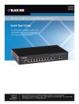
Download User Manual
Transcript
MT1500A T1/FT1 CSU/DSU, V.35 User Manual Customer Support Information BLACK BOX ® Order toll-free in the U.S.: Call 877-877-BBOX (outside U.S. call 724-746-5500) FREE technical support 24 hours a day, 7 days a week: Call 724-746-5500 or fax 724-746-0746 Mailing address: Black Box Corporation, 1000 Park Drive, Lawrence, PA 15055-1018 Web site: www.blackbox.com • E-mail: [email protected] T1/FT1 CSU/DSU, V.35 User Manual Trademarks Used in this Manual Black Box and the Double Diamond logo are registered trademarks of BB Technologies, Inc. Any other trademarks mentioned in this manual are acknowledged to be the property of the trademark owners. We‘re here to help! If you have any questions about your application or our products, contact Black Box Tech Support at 724-746-5500 or go to blackbox.com and click on “Talk to Black Box.” You’ll be live with one of our technical experts in less than 60 seconds. Page 2 724-746-5500 | blackbox.com T1/FT1 CSU/DSU, V.35 User Manual Table of Contents FCC and NOM Information..........................................................................................................................................................4 Safety Requirements....................................................................................................................................................................8 1. Product Description.............................................................................................................................................................. 10 1.1Description................................................................................................................................................................... 10 1.2 Applications.................................................................................................................................................................. 10 2.Installation............................................................................................................................................................................ 13 2.1Unpacking.................................................................................................................................................................... 13 2.2 Site Selection................................................................................................................................................................ 14 2.3 Mechanical and Electrical Installation........................................................................................................................... 14 2.3.1 Mechanical Installation........................................................................................................................................ 14 2.3.2 Electrical Installation............................................................................................................................................ 15 2.4 Configuration Setting................................................................................................................................................... 17 2.4.1 Hardware Configuraiton Setting.......................................................................................................................... 17 2.4.2 Software Configuration Setting.......................................................................................................................... 17 3.Operation............................................................................................................................................................................. 19 3.1 Quick Start for T1/FT1 CSU/DSU.................................................................................................................................. 19 3.1.1 Power On............................................................................................................................................................. 19 3.1.2 Return to Default Setting..................................................................................................................................... 19 3.2 Using Terminal Setup.................................................................................................................................................... 19 3.2.1 Review of Default Settings.................................................................................................................................20 3.3 System Operation......................................................................................................................................................... 21 3.3.1 Date.................................................................................................................................................................... 21 3.3.2 System Clock...................................................................................................................................................... 21 3.3.3 Console Port...................................................................................................................................................... 21 3.3.4 Security System.................................................................................................................................................. 21 3.3.5 Configuration.....................................................................................................................................................22 3.4 DS0 Channel Map........................................................................................................................................................22 3.5 T1 Network Line Configuration.....................................................................................................................................22 3.5.1 Frame Format Mode...........................................................................................................................................22 3.5.2 Line Code Mode................................................................................................................................................22 3.5.3 Line Build Out....................................................................................................................................................22 3.5.4 Density...............................................................................................................................................................23 3.5.5 Yellow Alarm......................................................................................................................................................23 3.5.6 Facility Data Link.................................................................................................................................................23 3.5.7 Inband Signaling.................................................................................................................................................23 3.5.8 Idle Code.............................................................................................................................................................23 3.6 DTE Configuration........................................................................................................................................................ 24 3.6.1 Speed.................................................................................................................................................................24 3.6.2 Request to Send (RTS)........................................................................................................................................24 3.6.3 Remote Loop..................................................................................................................................................... 24 3.6.4 DTE Interface Type.............................................................................................................................................24 3.7 System Clock................................................................................................................................................................24 3.8 Alarms and Indicators...................................................................................................................................................25 3.8.1 Alarrns................................................................................................................................................................25 3.8.2 Indicators...........................................................................................................................................................25 724-746-5500 | blackbox.com Page 3 T1/FT1 CSU/DSU, V.35 User Manual 3.9 Performance Registers..................................................................................................................................................26 3.9.1 ES — Errored Seconds........................................................................................................................................26 3.9.2 BES — Bursty Errored Seconds...........................................................................................................................27 3.9.3 SES — Severely Errored Seconds........................................................................................................................27 3.9.4 UAS — UnAvailable Seconds.............................................................................................................................27 3.9.5 Time in Interval...................................................................................................................................................27 3.9.6 Number of Valid Intervals...................................................................................................................................27 3.9.7 Performance Register Intervals............................................................................................................................27 3.10Event Log.....................................................................................................................................................................28 3.11 System Utilities............................................................................................................................................................. 28 3.11.1 Set System Date................................................................................................................................................29 3.11.2 Enter Unit Identification Number......................................................................................................................29 3.11.3 Clear System Configuration...............................................................................................................................29 3.11.4 Enter New Password.........................................................................................................................................29 3.11.5 Enable/Disable Security.....................................................................................................................................30 3.12 LED Operation..............................................................................................................................................................30 4. Maintenance.......................................................................................................................................................................32 4.1 System Initialization......................................................................................................................................................32 4.2 Near-End Loopback......................................................................................................................................................32 4.2.1 CSU Loopback....................................................................................................................................................32 4.2.2 Network interface Local Loopback — NI LLB.....................................................................................................32 4.2.3 Payload Loopback..............................................................................................................................................33 4.2.4 DTE Local Loopback...........................................................................................................................................33 4.3 Far-End Loopback.........................................................................................................................................................33 4.3.1 Remote Line Loopback (REM LN/LP)..................................................................................................................34 4.3.2 Remote Payload Loopback (REM PAYLD)...........................................................................................................34 4.3.3 Remote DTE Loopback (REM DTE/LP)................................................................................................................34 4.4 Verifying T1/FT1 CSU/DSU Operations.........................................................................................................................34 4.4.1 Quick Test...........................................................................................................................................................35 4.4.2 Substitution........................................................................................................................................................35 5. Console Operations..............................................................................................................................................................36 5.1 System Configuration...................................................................................................................................................36 5.1.1 DS0 Map..............................................................................................................................................................37 5.2 System Diagnostics.......................................................................................................................................................38 5.3 System Alarms and Indicators.......................................................................................................................................38 5.4 Performance Registers..................................................................................................................................................39 5.5 Event Log..................................................................................................................................................................... 41 5.6 System Utilities............................................................................................................................................................. 41 5.6.1 Set System Time.................................................................................................................................................42 5.6.2 Set System Date.................................................................................................................................................43 5.6.3 Enter Unit Identification Number........................................................................................................................43 5.6.4 Clear System Configuration................................................................................................................................44 5.6.5 Enter New Password..........................................................................................................................................44 5.6.6 Enable/Disable Security......................................................................................................................................45 Appendix A. PRBS (Pseudo-Random Bit Sequence)...................................................................................................................46 Appendix B. Menu Tree.............................................................................................................................................................47 Appendix C. Glossary of Abbreviations...................................................................................................................................... 51 Page 4 724-746-5500 | blackbox.com T1/FT1 CSU/DSU, V.35 User Manual Federal Communications Commission and Industry Canada Radio Frequency Interference Statements This equipment generates, uses, and can radiate radio-frequency energy, and if not installed and used properly, that is, in strict accordance with the manufacturer’s instructions, may cause interference to radio communication. It has been tested and found to comply with the limits for a Class A computing device in accordance with the specifications in Subpart B of Part 15 of FCC rules, which are designed to provide reasonable protection against such interference when the equipment is operated in a commercial environment. Operation of this equipment in a residential area is likely to cause interference, in which case the user at his own expense will be required to take whatever measures may be necessary to correct the interference. Changes or modifications not expressly approved by the party responsible for compliance could void the user’s authority to operate the equipment. This digital apparatus does not exceed the Class A limits for radio noise emission from digital apparatus set out in the Radio Interference Regulation of Industry Canada. Le présent appareil numérique n’émet pas de bruits radioélectriques dépassant les limites applicables aux appareils numériques de la classe A prescrites dans le Règlement sur le brouillage radioélectrique publié par Industrie Canada. 724-746-5500 | blackbox.com Page 5 T1/FT1 CSU/DSU, V.35 User Manual Instrucciones de Seguridad (Normas Oficiales Mexicanas Electrical Safety Statement) 1. T odas las instrucciones de seguridad y operación deberán ser leídas antes de que el aparato eléctrico sea operado. 2. Las instrucciones de seguridad y operación deberán ser guardadas para referencia futura. 3. Todas las advertencias en el aparato eléctrico y en sus instrucciones de operación deben ser respetadas. 4. T odas las instrucciones de operación y uso deben ser seguidas. 5. E l aparato eléctrico no deberá ser usado cerca del agua—por ejemplo, cerca de la tina de baño, lavabo, sótano mojado o cerca de una alberca, etc. 6. E l aparato eléctrico debe ser usado únicamente con carritos o pedestales que sean recomendados por el fabricante. 7. El aparato eléctrico debe ser montado a la pared o al techo sólo como sea recomendado por el fabricante. 8. S ervicio—El usuario no debe intentar dar servicio al equipo eléctrico más allá a lo descrito en las instrucciones de operación. Todo otro servicio deberá ser referido a personal de servicio calificado. 9. El aparato eléctrico debe ser situado de tal manera que su posición no interfiera su uso. La colocación del aparato eléctrico sobre una cama, sofá, alfombra o superficie similar puede bloquea la ventilación, no se debe colocar en libreros o gabinetes que impidan el flujo de aire por los orificios de ventilación. 10. E l equipo eléctrico deber ser situado fuera del alcance de fuentes de calor como radiadores, registros de calor, estufas u otros aparatos (incluyendo amplificadores) que producen calor. 11. E l aparato eléctrico deberá ser connectado a una fuente de poder sólo del tipo descrito en el instructivo de operación, o como se indique en el aparato. 12. P recaución debe ser tomada de tal manera que la tierra fisica y la polarización del equipo no sea eliminada. 13. L os cables de la fuente de poder deben ser guiados de tal manera que no sean pisados ni pellizcados por objetos colocados sobre o contra ellos, poniendo particular atención a los contactos y receptáculos donde salen del aparato. 14. El equipo eléctrico debe ser limpiado únicamente de acuerdo a las recomendaciones del fabricante. 15. E n caso de existir, una antena externa deberá ser localizada lejos de las lineas de energia. 16. El cable de corriente deberá ser desconectado del cuando el equipo no sea usado por un largo periodo de tiempo. 17. Cuidado debe ser tomado de tal manera que objectos liquidos no sean derramados sobre la cubierta u orificios de ventilación. 18. S ervicio por personal calificado deberá ser provisto cuando: A: El cable de poder o el contacto ha sido dañado; u B: Objectos han caído o líquido ha sido derramado dentro del aparato; o C: El aparato ha sido expuesto a la lluvia; o D: El aparato parece no operar normalmente o muestra un cambio en su desempeño; o E: El aparato ha sido tirado o su cubierta ha sido dañada. Page 6 724-746-5500 | blackbox.com T1/FT1 CSU/DSU, V.35 T1/FT1 CSU/DSU, V.35 registration number and REN are as follows: FCC 68 Registration Number: 1U5USA-33109-DE-N REN: 0.0B FACILITY INTERFACE CODE FOR DIGITAL SERVICES CODE DESCRIPTION 04DU9-BN 1.544 Mbps Superframe Format (SF) without line power. 04DU9-DN 1.544 Mbps SF and B8ZS without line power. 04DU9-1KN 1.544 Mbps ANSI ESF without line power. 04DU9-1SN 1.544 Mbps ANSI ESF and B8ZS without line power. CODE 6.0N SERVICE ORDER CODES FOR DIGITAL SERVICES DESCRIPTION Does not provide billing and encoded analog protection. Uses either an integrated or external CSU. Affidavit to telco is required. The T1/FT1 CSU/DSU connects to the network using an RJ-48 connector. If this equipment causes harm to the telephone network, the telephone company will notify you in advance that temporary discontinuance of service may be required. If advance notice isn't practical, the Telephone Company will notify the customer as soon as possible. Also, you will be advised of your right to file a compliant with the FCC if you believe it is necessary. The telephone company may make changes in its facilities, equipment, operations, or procedures that could affect the operation of the equipment. If this happens, the Telephone Company will provide advance notice in order for you to make the necessary modifications in order to maintain uninterrupted service. Normally, this equipment will be used in conjunction with FCC registered equipment that limits the Encoded Analog Content and provides the required Billing Protection. If the connected equipment is not of this type, an affidavit must be supplied to the telephone company where the network connection is to be made. The affidavit is to be notarized, and is to be filed at least ten days before the initial connection. If you have trouble with this equipment, please contact Black Box Tech Support for repair and warranty information. If the trouble is causing harm to the telephone network, the Telephone Company may request you remove the equipment from the network until the problem is resolved. This equipment cannot be used on telephone company-provided coin service. Connection to Party Line Service is subject to state tariffs. Black Box Corporation Phone: 724-746-5500 Email: [email protected] MT1500A Rev. 1 T1/FT1 CSU/DSU, V.35 – USER GUIDE 7 T1/FT1 CSU/DSU, V.35 Safety Requirements CAUTION: a. Never install telephone wiring during a lightning storm. b. Never install telephone jacks in wet locations unless the jack is specifically designed for wet locations. c. Never touch un-insulated telephone wires or terminals unless the telephone line has been disconnected at the network interface. d. Use caution when installing or modifying telephone lines. Refer to the installation chapter in this manual for a safe and proper installation procedure. All wiring external to this equipment should follow the current provision of the National Electrical Code. National Electrical Code Requirements The T1/FT1 CSU/DSU, including this equipment, is in compliance with CSA NRTLC 1950 Third Edition and as such, UL 1950. The CSA control number for the T1/FT1 CSU/DSU is LR113152. DOC CS-03 Requirements NOTICE: The Canadian Department of Communications label identifies certified equipment. This certification means that the equipment meets certain telecommunications network protective, operational and safety requirements. The Department does not guarantee the equipment will operate to the user's satisfaction. Before installing this equipment, user should ensure that it is permissible to be connected to the facilities of the local telecommunications company. The equipment must also be installed using an acceptable method of connection. In some cases, the company's inside wiring associated with a single line individual service may be extended by means of a certified connector assembly (telephone extension cord). The customer should be aware that compliance with the above conditions may not prevent degradation of service in some situations. MT1500A Rev. 1 T1/FT1 CSU/DSU, V.35 – USER GUIDE 8 T1/FT1 CSU/DSU, V.35 Repairs to certified equipment should be made by an authorized Canadian maintenance facility designated by the supplier. Any repairs or alternations made by the user to this equipment, or equipment malfunctions, may give the telecommunications company cause to request the user to disconnect the equipment. User should ensure for their own protection that the electrical ground connections of the power utility, telephone lines and internal metallic water pipe system, if present, are connected together. This precaution may be particularly important in rural areas. Caution: User should not attempt to make such connections themselves, but should contact the appropriate electric inspection authority, or electrician, as appropriate. The Load Number (LN) assigned to each terminal device denotes the percentage of the total load to be connected to a telephone loop that is used by the device, to prevent overloading. The termination on a loop may consist of any combination of devices subject only to the requirement that the total of the Load Number of all the devices does not exceed 100. Standard Lists T1/FT1 CSU/DSU is designed to meet the following standards: • MT1500A Rev. 1 AT&T 62411, AT&T 54016, ANSI T1.403 T1/FT1 CSU/DSU, V.35 – USER GUIDE 9 T1/FT1 CSU/DSU, V.35 1.0 Product Description 1.1 Description The T1/FT1 is a standalone intelligent Fractional T1 Channel Service Unit and Data Service Unit (CSU/DSU). This product family provides a T1 network interface, DS0 channel multiplexing, and direct connections to data and video DTE (Data Terminal Equipment). Table 1-1. T1 Spartan T1/FT1 CSU/DSU Product Family Model T1/FT1 CSU/DSU NI (Network Interface) Physical Stand-Alone 100 ohm Twisted Pair T1 – One Port DTE Port V.35 / M34 EIA530 / M34 The T1/FT1 CSU/DSU can be configured via the local terminal (RS-232/VT-100) control interface. 1.2 Applications The T1/FT1 CSU/DSU application examples are illustrated in Figures 1-2 through 1-5. Via DACS (Digital Access Cross-Connect System), the T1/FT1 interfaces various applications such as LAN (Local Area Network) to WAN (Wide Area Network) communications, host to workstation communications, and video conferencing. This allows the user to integrate different applications into a single communication link using only part of the available bandwidth. Furthermore, this allows the user to expand bandwidth, up to 24 DS0 channels, on demand without additional physical links because they are already available. Data and video applications may include equipment such as video conferencing, bridge, router, gateway, workstation, host computer, and various high-speed data terminal equipment. MT1500A Rev. 1 T1/FT1 CSU/DSU, V.35 – USER GUIDE 10 T1/FT1 CSU/DSU, V.35 Figure 1-1. Application Illustration -1 Figure 1-2. Application Illustration -2 MT1500A Rev. 1 T1/FT1 CSU/DSU, V.35 – USER GUIDE 11 T1/FT1 CSU/DSU, V.35 Figure 1-3. Application Illustration -3 Figure 1-4. Application Illustration -4 MT1500A Rev. 1 T1/FT1 CSU/DSU, V.35 – USER GUIDE 12 T1/FT1 CSU/DSU, V.35 2.0 Installation CAUTION: 2.1 • Never install telephone wiring during a lightning storm. • Never install telephone jacks in wet locations unless the jack is specifically designed for wet locations. • Never touch un-insulated telephone wires or terminals unless the telephone line has been disconnected at the network interface. • Use caution when installing or modifying telephone lines. Unpacking This product is shipped in a complete package, which contains the T1/FT1 CSU/DSU and accessories. Check the shipping material against Table 2-1, Shipping Material List. Table 2-1. Shipping Material List Description Item T1/FT1 CSU/DSU (120 ohm) ∗ ∗ items vary depending on the order T1/FT1 CSU/DSU options User's Manual Power Cord with External Transformer Cable: RJ48C to RJ48C (T1 NI Interface) Cable: DB9 to DB25 (Console - Serial) Cable: V.35/M35 male to V.35/M34 male (DTE Interface) Part Number MT1500A Included Included Included Special Order Special Order Inspect the unit for any signs of damage. Report any damage to the carrier and contact Black Box Technical Support at 724-746-5500 or [email protected]. Retain all packaging material in case you need to move or ship the unit in the future. MT1500A Rev. 1 T1/FT1 CSU/DSU, V.35 – USER GUIDE 13 T1/FT1 CSU/DSU, V.35 Site Selection 2.2 Follow the guidelines listed below when selecting the installation site. • The installation site should have an AC power receptacle. • The following are the maximum suggested cable lengths: • V.35 • EIA530 15 m (50 ft,) 15 m (50 ft.) NOTE: If longer distance is needed, a lower than maximum speed with proper cabling and grounding is advisable. For more information, contact Black Box Technical Support at 724-746-5500 or [email protected]. • The installation site should provide space for adequate ventilation and cable routing. Reserve at least 12 cm (5 inches) at the rear of the unit for cables and airflow. • The site should provide a stable environment. The operating area should be clean and free from extremes of temperature, humidity, shock and vibration. • Relative humidity should stay between 0 and 95%. Do not operate the unit at an altitude greater than 3000 meters (10,000 feet). Mechanical and Electrical Installation 2.3 2.3.1 Mechanical Installation Figure 2-1. T1/FT1 CSU/DSU Front Panel View The T1/FT1 CSU/DSU Stand-Alone version is a desktop unit, which is stackable. The front panel is shown in Figure 2-1, and the rear panel is shown in Figure 2-2. MT1500A Rev. 1 T1/FT1 CSU/DSU, V.35 – USER GUIDE 14 T1/FT1 CSU/DSU, V.35 Figure 2-2. T1/FT1 CSU/DSU Rear Panel 2.3.2 Electrical Installation The T1/FT1 CSU/DSU Stand-Alone version is AC powered. Use the rear right power connector to connect to an AC power outlet using the inline power transformer and cord provided. The console port is the DB9 connector. For this interface the T1/FT1 CSU/DSU is configured as a DCE device. This port may be connected directly to a DTE device. Pin definitions and pin connections are listed in Table 2-2. Table 2-2. DB9 Console – Serial Port Pin Number Signal Source 1 Unassigned 2 Receive Data DTE 3 Transmit Data DCE 4 Data Terminal Ready DTE 5 Ground DCE-DTE 6 Data Set Ready DCE 7 Request To Send DTE 8 Clear To Send DCE 9 Unassigned Table 2-3. RJ-48 Line Connector Pin Number Signal Signal Direction 1 Receive Ring From T1 Network 2 Receive Tip From T1 Network 3 Unassigned 4 Transmit Ring To T1 Network 5 Transmit Tip To T1 Network 6 Unassigned 7 Unassigned 8 Unassigned MT1500A Rev. 1 T1/FT1 CSU/DSU, V.35 – USER GUIDE 15 T1/FT1 CSU/DSU, V.35 The DTE port is configured as a DCE device. All available signaling appears on an M34 connector. There are 3 different interfaces supported from the M34 connector. Signaling Interfaces: V.35/M34 and EIA530/M34. The T1 Spartan automatically recognizes each signaling convention and requires NO menu selection or manipulation. Appropriate conversion cables are available from ATL for EIA530 connections. Pin definitions are defined in Tables 2-4 to 2-5. Table 2-4. V.35/M34 DTE Port Pin Definition Pin Number A B C D E F H J K L M N P R S T U V W X Y Z AA BB CC DD EE FF HH JJ KK LL MM NN MT1500A Rev. 1 Signa Cable Shield l Signal Ground Request To Send Clear To Send Data Set Ready Data Carrier Detect Data Terminal Ready Unassigned Unassigned Unassigned Unassigned Unassigned Transmit Data Receive Data Transmit Data Return Receive Data Return External Clock Receive Clock External Clock Return Receive Clock Return Transmit Clock Unassigned Transmit Clock Return Unassigned Unassigned Unassigned Unassigned Unassigned Unassigned Unassigned Unassigned Unassigned Unassigned Unassigned T1/FT1 CSU/DSU, V.35 – USER GUIDE Sourc e DTE DCE DCE DCE DTE DTE DCE DTE DCE DTE DCE DTE DCE DCE DCE 16 T1/FT1 CSU/DSU, V.35 Table 2-5. EIA530/DB25 DTE Port Pin Definition Pin Number 1 2 3 4 5 6 7 8 9 10 11 12 13 14 15 16 17 18 19 20 21 22 23 24 25 2.4 Signa Cable Shield l Transmit Data Receive Data Request To Send Clear To Send Data Set Ready Signal Ground Data Carrier Detect Receive Clock Return Data Carrier Detect Return External Clock Return Transmit Clock Return Clear To Send Return Transmit Data Return Transmit Clock Receive Data Return Receive Clock Local Loopback Request To Send Return Data Terminal Ready Remote Loopback Data Set Ready Return Data Terminal Ready Return External Clock Test Mode Sourc e DTE DCE DTE DCE DCE DCE DCE DCE DTE DCE DCE DTE DCE DCE DCE DTE DTE DTE DTE DCE DTE DTE DCE Configuration Setting 2.4.1 Hardware Configuration Setting All configurations are software programmable. No DIP switches are available. Users should not open the case. 2.4.2 Software Configuration Setting There is a single configuration that is maintained for the T1/FT1 CSU/DSU in battery-backed-up random access memory, or non-volatile memory. The factory default configuration is not changeable. Each T1/FT1 CSU/DSU is shipped with the factory default configuration. The current configuration can be changed at any time. The system automatically stores the current configuration into non-volatile memory. When the system is turned off and then turned back on again, the previous configuration is retrieved as the current configuration. MT1500A Rev. 1 T1/FT1 CSU/DSU, V.35 – USER GUIDE 17 T1/FT1 CSU/DSU, V.35 The factory default configuration may be set into the T1/FT1 CSU/DSU at any time by using the Utility routine, “Clear System Configuration” from the console terminal interface. Table 2-7 lists all factory defaults (below). Table 2-6. Default Software Configuration T1 Network Interface Framing Line Code LBO Network Diagnostics Density Yellow Alarm ESF Format Clear Registers (Statistics) Default ESF B8ZS 0 db No Clear Off 54016 Yes Timing Source Source Default Network Interface (NI) Serial Port (DTE) Rate RTS Clocks (Source) Remote Loop (Enabled) Default 64K * N Constant Line Yes DS0 Map All Channels Default DTE Port Console Port Port Speed Data Bits Parity XON-XOFF Flow Control Default 9600 bps 8 None No Security Enabled/Disabled Password Default Disabled Default Miscellaneous All Loops All Bert Functions Event Log ESF Statistics Date/Time Software Version MT1500A Rev. 1 Default Off Off Cleared Cleared Unchanged Unchanged T1/FT1 CSU/DSU, V.35 – USER GUIDE 18 T1/FT1 CSU/DSU, V.35 3.0 Operation This chapter describes the T1/FT1 CSU/DSU configuration options and operational functions. The user should refer to Chapter 5: Front Panel Operation and Chapter 6: Terminal Operation for detailed operational procedures. 3.1 Quick Start for T1/FT1 CSU/DSU After installation, the user may want to become familiar with the equipment immediately. The following abbreviated instructions will give the user a quick start. 3.1.1 Power On Connect power by attaching the power/transformer cable at the rear of the unit. LEDs will then cycle through. 3.1.2 Return to Default Setting The unit is shipped with factory default settings. To restore the factory settings in the future, use the main menu Utility routine – “Clear System Configuration”. See Section 2 for factory default values that are restored. 3.2 Using Terminal Setup To use an RS-232 interface to configure the unit, connect a VT-100 terminal to the DB9/RS-232 connector using a DB9–DB25 cable. The VT-100 terminal can be a PC running VT-100 emulation software. The DB9–DB25 configures the console port as a DCE. Thus a null modem plug or cable is not required for direct connection to a VT-100 (DTE device). As soon as the T1/FT1 CSU/DSU detects the presence of Data Terminal Ready (DTR) it will output an initial screen. Normal operation of the terminal/T1 will show the following leads active: Pin 2 – DTE/TX, Pin 3 – DTE/RX, Pin 4 – DTE/RTS, Pin 5 – DCE/CTS, Pin 6 – DCE/DSR, Pin 7 – DTE/DCE Ground, Pin 8 – DCE/CD, Pin 20 – DTE/DTR. Should the terminal interface fail to operate, carefully check the above leads. If “Security” is enabled, the initial screen will be a request for a password. If “Security” is disabled, the initial screen will be the ATL MAIN MENU screen. MT1500A Rev. 1 T1/FT1 CSU/DSU, V.35 – USER GUIDE 19 T1/FT1 CSU/DSU, V.35 3.2.1 Review of Default Settings The MAIN MENU allows the user to enter any of the subsystems of the T1 Spartan: System Configuration, System Diagnostics, System Alarms and Indicators, Performance Registers, Event Log, and System Utilities. The following keys provide for a means to traverse the menu system: Cursor Up = [Up Arrow], Cursor Down [Down Arrow], Select Entry/Go Down In Menu = [ENTER], Go Up In Menu = [ESC twice]. On the MAIN MENU screen is also displayed the model number of the T1 Spartan, the Software version, the current Date and Time, the Unit ID, and the current System Status. PRESS ENTER TO VIEW THE SYSTEM CONFIGURATION SCREEN. 3.1.2.1 Line Use “Up Arrow” and “Down Arrow” keys to select any Line parameter that requires changing. Use “Right Arrow” to change to a desired parameter. 3.1.2.2 Serial Port – DTE Use “Up Arrow” and “Down Arrow” keys to select any Serial Port parameter that requires changing. Use “Right Arrow” to change to a desired parameter. 3.1.2.3 System Clock Use “Up Arrow” and “Down Arrow” to select the System Clock parameter which requires changing. Use “Right Arrow” to change to a desired parameter. 3.1.2.4 DS0-Map Setup Press “ENTER” to go to the DS0-Map menu. Use “Up Arrow” and “Down Arrow” keys to select the DS0 channel (S) you wish to modify. Use “Right Arrow” to change to a desired parameter. Press “ESC” twice when all changes have been made. Press “ESC” twice, again, to return to the MAIN MENU. MT1500A Rev. 1 T1/FT1 CSU/DSU, V.35 – USER GUIDE 20 T1/FT1 CSU/DSU, V.35 3.3 System Operation 3.3.1 Date This product is equipped with a RTC (Real Time Clock). The user can change the current date and time as required. The RTC is activated by the manufacturer before shipping. This is to save RTC battery life. The RTC battery has a 10-year power off life cycle. 3.3.2 System Clock This product has a system clock PLL (Phase Lock Loop) which may be phase locked to the T1 line or the internal oscillator clock of the T1 Spartan. The T1 line signal and the internal clock of the T1 Spartan are all 1.544 Mbps. The default system clock is derived from the T1 line signal often referred to as the Network Interface or NI for short. 3.3.3 Console Port The console port allows the user to use a local VT-100 terminal via a DB9/RS232 cable connection for system configuration, diagnostics, utilities, etc. The console port must be set to a proper operational mode. The default console port baud rate, data bit length, parity bit length, and XON-XOFF flow control are set as shown in Table 3-1. Table 3-1. Console Port Default Setting Item Options Baud Rate 9600 Data Bit 8 Parity Bit NONE XON-XOFF OFF Default 9600 8 NONE OFF 3.3.4 Security System The terminal is used to read events, system configurations, diagnostics, and system status. It can also be used to change system configurations and clear the event log, etc. By enabling the security system, the user may restrict terminal access to users who know the password stored in the system. The default password stored in the T1/ F T 1 C S U / D S U prior to factory shipment is “Default”. Once the Security System is enabled, the user may enter any new password into the T1/FT1 CSU/DSU after providing the old password. MT1500A Rev. 1 T1/FT1 CSU/DSU, V.35 – USER GUIDE 21 T1/FT1 CSU/DSU, V.35 • Password and Security System options are disabled by default. • The default terminal access password is default. 3.3.5 Configuration The system automatically saves the current configuration into non-volatile memory. The configuration is thus available each time the unit is powered up. After a power cycle, the current configuration is retrieved and used by the T1/FT1 CSU/DSU. 3.4 DS0 Channel Map DS0 channel multiplexing is done by the DS0-MAP command. A map contains 24 DS0 channels where a single DS0 channel can be assigned to a DTE port or not used. An idle code is transmitted on all unused channels. 3.5 T1 Network Line Configuration A detailed option list of the T1 line configuration parameters is in Table 3-2. The following paragraphs will describe each item. 3.5.1 Frame Format Mode This equipment can be used as a T1/FT1 D4 or ESF frame format DS1 network interface. In ESF frame format mode, the user can choose either AT&T or ANSI facility data link protocol. ESF & T1.403 chooses ANSI ESF data link protocol and a performance report will be sent to the network every second automatically. Also, ANSI and AT&T data link messages are acceptable in ANSI ESF frame format mode. However, AT&T ESF frame format mode only accepts AT&T ESF data link protocol. 3.5.2 Line Code Mode The T1/FT1 CSU/DSU can be used in AMI (Alternate Mark Inversion) or B8ZS (Bipolar Eight Zero Substitution) line code format. 3.5.3 Line Build Out The T1 line long haul transmit LBO can be programmed to 0 dB, -7.5 dB, -15 dB, or –22 dB relative to the DS1 transmit level. MT1500A Rev. 1 T1/FT1 CSU/DSU, V.35 – USER GUIDE 22 T1/FT1 CSU/DSU, V.35 3.5.4 Density The 1’s density of the T1/FT1 CSU/DSU may be set to either “Clear” or “62411”. The “Clear” parameter selection causes the T1 Spartan to make no modifications to the 1’s density of the T1 bit stream. This is sufficient for the line code format that is B8ZS, since B8ZS guarantees a sufficient 1’s density. For a line code mode of AMI, the user may wish to select "62411” which will guarantee a sufficient 1’s density. 3.5.5 Yellow Alarm The T1/FT1 CSU/DSU transmits a yellow alarm when LOS (Loss of Signal) is detected, AIS (Alarm Indication Signal), is detected, or OOF (Out of Frame) is detected for 2.5 +0.5 seconds. Users may disable this feature by setting Yellow Alm to “Off”. 3.5.6 Facility Data Link The T1/FT1 CSU/DSU uses a proprietary facility data link to initiate remote system control, performance and statistics monitoring. In addition, the facility data link is also used to cause proprietary loop backs in a remote T1 Spartan unit. 3.5.7 Inband Signaling Using T1 D4 framing format and ESF, (both ESF and ESF &T1.403), an inband loopback recognition is used to activate remote loopback operation. This is primarily done by a circuit provider who is testing a circuit. 3.5.8 Idle Code Any DS0 channel, which is not assigned to a DTE port, is an idle channel. An idle code is transmitted on the idle DS0 channels. The idle code is set to FFh by the T1 Spartan and may not be modified by the user. The idle code is inserted into unused channels after any data inversion, if activated. Table 3-2. T1 Line Default Setting Item Frame Format Mode Line Code Line Build Out Density Network Diagnostics Yellow Alarm ESF Format MT1500A Rev. 1 Option s ESF, D4, Not Used (N/U) B8ZS, AMI 0, 7.5, 15, 22 dB Clear, 62411 No, Yes Off, On 54016, T1.403 T1/FT1 CSU/DSU, V.35 – USER GUIDE Default ESF B8ZS 0 dB Clear No Off 54016 23 T1/FT1 CSU/DSU, V.35 3.6 DTE Configuration (Serial Port) This product is equipped with one port. The information provided is specific to the Serial Port of the T1/FT1 CSU/DSU. A detailed option list of DTE configuration parameters is in Table 3-3, and the following paragraphs describe each parameter. 3.6.1 Speed The DTE port can operate at 56KxN or 64KxN bps, (N is 1 to 24). Use the Speed selection parameter to select 56K or 64K. Use DS0 MAP selection parameters to select the activity of the DS0 channels that the DTE port contains. 3.6.2 Request to Send (RTS) The DTE facility can use RTS (Request To Send) to control transmission. When RTS is “External” and in the OFF state, all ones are sent to the T1 line side on the DTE port associated with the DS0 channels. When RTS is “Constant”, the RTS signal is ignored and forced ON permanently. 3.6.3 Remote Loop The T1/FT1 CSU/DSU is either enabled or disabled to receive a proprietary remote loop command from a T1/FT1 CSU/DSU connected to the other end of a circuit. 3.6.4 DTE Interface Type The DTE Serial Port interface type can be V.35 or EIA530. The CSU/DSU automatically senses which interface is present. The user is not required to make any configuration changes. The physical port is a M.34 (female) pinned as a V.35, requiring a cable conversion to EIA-530 (DB-25). Table 3-3. DTE Serial Port Default Setting Item Option Speed 56K x N, 64K x N (N = 1s- 24) Request To Send (RTS) Constant, External Remote Loop Enabled, Disabled Default 56K x N Constant Enabled 3.7 System Clock The system clock source may be any of two sources: the Network Interface (NI) or the Internal Oscillator (INT – T1/FT1 CSU/DSU internal oscillator). The default is shown in Table 3-5. MT1500A Rev. 1 T1/FT1 CSU/DSU, V.35 – USER GUIDE 24 T1/FT1 CSU/DSU, V.35 Table 3-4. System Clock Default Setting Item System Clock NI, INT Option s Default NI 3.8 Alarms and Indicators 3.8.1 Alarms The T1/FT1 CSU/DSU has many types of alarms as listed in Table 3-5. Also, the T1/FT1 C S U / D S U has an Event Log that records the latest 32 alarms with a time and date stamp. Below is listed each alarm together with its meaning and description. 3.8.2 LOS – Loss of Signal LOS is declared following 175 bit times +75 bit times if no pulses of either positive or negative orientation are received by the T1/FT1 CSU/DSU. AIS – Alarm Indication Signal The AIS alarm is both generated by the CSU/DSU and received by the CSU/DSU. The AIS itself is a bit stream of all 1’s. A LOS condition causes the T1 Spartan to output an AIS pattern. In a similar manner, AIS is received by the T1/ F T 1 C S U / D S U when a remote unit, either CSU/DSU or central office unit, is in a LOS condition. Red – Alarm Red alarm is declared by the T1/ F T 1 C S U / D S U when it receives 192 consecutive 0s. Yellow – Alarm Yellow alarm is declared whenever a signal is present but the T1/FT1 CSU/DSU is unable to secure synchronization with it. FErr – Frame Error Alarm The T1/FT1 CSU/DSU receives a framing pattern in the 193rd bit position. FErr is declared when the T1 CSU/DSU detects an error in the framing pattern received. MT1500A Rev. 1 T1/FT1 CSU/DSU, V.35 – USER GUIDE 24 T1/FT1 CSU/DSU, V.35 CRC6 – Circular Redundancy Check 6 Alarm In ESF mode, a circular redundancy check is generated as a result of the data processed from previous frame(s). Whenever the generated circular redundancy check does not match the calculated circular redundancy check value, a CRC6 alarm is declared. BPV – BiPolar Violation Alarm When the line code is set to B8ZS, BPV reflects the number of bipolar violations that have occurred not counting the code words of the B8ZS. In AMI mode, any bipolar violations are reflected in the BPV count. In other words, any BPV is reflective of an error that has occurred. Table 3-5. Alarm Type Table ALA LOS AIS Red Yello FErr CRC BPV 3.8.2 R M T Y w P E 6 ALARM DESCRIPTION Loss Of Signal on Network Interface/DSX Alarm Indication Signal – all 1’sreceived All 0’s being Loss of frame synchronization Frame error detected Circular Redundancy Check error Bit errors are occurring Indicators The Indicators presented include the real time status of “Request To Send” (RTS), “Data Carrier Detect” (DCD), and the current status of loops that may be active at the Network Interface and the DTE port. RTS – Request to Send RTS is a control signal presented by the DTE device when it is ready to transmit data to the CSU/DSU. In the “Configuration” section of the T1/FT1 CSU/DSU, RTS is described as either Constant or External. If the CSU/DSU is declared Constant, it is assumed to be present all of the time and shown as present regardless of whether it is present or not. If External, the true status of the control signal of the DTE is shown in real time. MT1500A Rev. 1 T1/FT1 CSU/DSU, V.35 – USER GUIDE 25 T1/FT1 CSU/DSU, V.35 CTS – Clear to Send CTS is a control signal presented by the T1/FT1 CSU/DSU to the DTE indicating when it is permitted to receive transmitted data from the DTE device. The state of CTS is governed by several conditions. First, if the Network Interface is in an abnormal condition, CTS is held low indicating to the DTE device not to transmit data. Second, if RTS is External and the DTE device is not presenting the RTS signal, then the CTS signal is held low. DCD – Data Carrier Detect DCD is a control signal presented by the T1 Spartan to the DTE indicating a signal is present at the Network Interface and that it is possible to transmit data from the DTE device. If RTS is set to Constant, DCD is always shown as present regardless of the state of the Network Interface. DTR – Data Terminal Ready DTR is a control signal presented by the DTE to the T1 Spartan. DTR generally reflects the DTE’s ability to receive data from the T1/FT1 CSU/DSU. If RTS is set to Constant, DTR is always shown as present regardless of the state of the Data Terminal Equipment attached. Loop Status For real time status purposes, the existence of a loop condition is shown for each physical part of the T1/FT1 CSU/DSU– NI and DTE. 3.9 Performance Registers The T1/FT1 CSU/DSU has four performance registers that reflect operational statistics of the unit. A summary of the performance registers and their meaning are listed in Table 3-7. Each parameter is described in detail below. 3.9.1 ES – Errored Seconds In T1/D4 line format, the definition of ES is the number of bipolar violations that have occurred during any second interval. In T1/ESF line format, the definition of ES is the number of CRC6 errors plus the number of OOF errors detected within any one second. Both current counts and the past 24 hour counts are displayed. MT1500A Rev. 1 T1/FT1 CSU/DSU, V.35 – USER GUIDE 26 T1/FT1 CSU/DSU, V.35 3.9.2 BES – Bursty Errored Seconds In T1/D4 line format, this information is not available or defined. In T1/ESF line format, it is the total number of CRC6 errors that have occurred divided by 320. Both current counts and the past 24 hour counts are displayed. 3.9.3 SES – Severely Errored Seconds In T1/D4 line format, SES is the total number of bipolar violations divided by T1 Spartan in any one second. In T1/ESF line format, SES is the number of CRC errors divided by 320 plus the number of occurrences of OOF. Both current counts and the past 24 hour counts are displayed. 3.9.4 UAS – UnAvailable Seconds In both T1/D4 and T1/ESF line formats, UAS is the number of occurrences of 10 or greater Severely Errored Seconds during any one second. . Both current counts and the past 24 hour counts are displayed. 3.9.5 Time in Interval An interval is 15 minutes duration. There are 96 intervals in 24 hours. The time in interval parameter shows the number of seconds within any 15-minute interval. 3.9.6 Number of Valid Intervals The number of valid intervals is a count of up to 96 that indicates the number of previously recorded intervals that have been saved by the T1/FT1 CSU/DSU. Each previously recorded interval is available for viewing on two separate screens. 3.9.7 Performance Register Intervals Press “ENTER” from the Performance Register screen display, and the T1/FT1 CSU/DSU goes to the next screen in the menu system – Performance Register Intervals. This screen is composed of two screens of 48 groupings of intervals on each page. Press the “ENTER” key successively, and the two screens alternately display. Each interval displayed represents 15 minutes of CSU/DSU operation. In each interval, the number of Errored Seconds (ES), UnAvailable Seconds (UAS), Severely Errored Seconds (SES), and Bursty Errored Seconds (BES) is displayed. After 24 hours of operation, the display begins to overlay 24-hour-old information with current interval information. The Performance Register Intervals display is actually a First In First Out queue. The newest complete 15 minute interval appears in Interval “01”. The interval that is fifteen minutes older than the current interval appears in Interval “02”. The 23 hours 45 minutes old interval appears in Interval “96”. Each interval can be correlated with the actual time of day. Any interval not containing valid information is shown as “NOT VALID INTV”. MT1500A Rev. 1 T1/FT1 CSU/DSU, V.35 – USER GUIDE 27 T1/FT1 CSU/DSU, V.35 Table 3-6. Performance Parameter List Performance Description Parameter ES Errored Seconds BES Bursty Errored Seconds SES Severely Errored Seconds UAS Unavailable Seconds Definition (T1/D4) BPV≥1 Not Available BPV ≥ T1/FT1 CSU/DSU Definition (T1/ESF) CRC6 Error ≥ 1, OOF ≥1 1 < CRC6 < 320 CRC ≥ 320, or OOF ≥ 1 ≥ 10 consecutive SES ≥ 10 consecutive SES 3.10 Event Log The Event Log contains 32 chronological entries. Each entry is date and time stamped to indicate when it occurred. In addition, a status is provided indicating additional information about the event. Typical status will include the “Start” and “End” of a particular event. The event itself is identified as to source and type of event. All alarms are placed in the Event Log. When the number of events exceeds 32, the log operates as a First In First Out (FIFO) queue. Thus the last 32 events in time are always available for viewing. The Event Log screen is NOT updated in real time. Upon entry to the Event Log, the current Event Log is presented. To see additional entries that may have been added since viewing the Event Log, press “ESC” twice, and then re-enter the Event Log. 3.11 System Utilities System Utilities routines include: Set System Time Set System Date Enter Unit Number Clear Configuration Password Identification Enter System New Enable/Disable Security The system time is set at the factory and reflects Mountain Time. The user may change the system time by selecting the System Utilities – Set System Time function and pressing Enter. A small box is located near the center of the CRT screen containing the current Hours/Minutes/Seconds (Note: military time is used, where hours go from 0 to 23). The cursor is positioned to the hours field. To change the system time enter a new value for hours, minutes, and seconds. The Right Arrow and Left Arrow keys are also active allowing the user to skip over fields that are correct as is. When the update is complete, press “ESC” twice to go back up to the main utilities screen. MT1500A Rev. 1 T1/FT1 CSU/DSU, V.35 – USER GUIDE 28 T1/FT1 CSU/DSU, V.35 3.11.1 Set System Date The user may change the system date by selecting the System Utilities – Set System Date function and pressing Enter. A small box is located near the center of the CRT screen containing the current Month/Day/Year. The cursor is positioned to the month field. To change the system date enter a new value for month, day, and year. The Right Arrow and Left Arrow keys are also active allowing the user to skip over fields that are correct as is. When the update is complete, press “ESC” twice to go back up to the main utilities screen. 3.11.2 Enter Unit Identification Number The user may change the system Unit ID by selecting the System Utilities – Enter Unit Identification Number function and pressing Enter. A small box is located near the center of the CRT screen containing the current Unit Identification Number. The default Unit Identification Number is “00000001”. The cursor is positioned to the beginning of the numeric Unit Identification field. To change the Unit Identification Number, use the numeric keys to overwrite a new eight-digit number. The Unit Identification Number appears on certain CRT screens and helps to provide a unique identifier if screens are copied to a printer for later review. The Right Arrow and Left Arrow keys are also active allowing the user to skip over digits that are correct as is. When the update is complete, press “ESC” twice to go back up to the main utilities screen. 3.11.3 Clear System Configuration The user may clear the current system configuration back to the factory default settings. Position the cursor on the main System Utilities screen to “Clear System Configuration” and press Enter. A small box is located near the center of the CRT screen containing a verification question “Clear All Configuration!!!”. A response of either (Y)es or (N)o is requested. If “N” is entered, the T1 Spartan returns to the main System Utilities screen. If “Y” is entered, a new message appears “<<< ARE YOU SURE!!! >>>, followed by (Y)es or (N)o. This is a second verification screen as a safeguard against accidental resetting of the system to a factory configuration. If “N” is entered, the system returns to the main System Utilities screen. If “Y” is entered, the entire T1 Spartan is reset to the factory configuration, the system is re-booted, and the main Console menu appears on the CRT following initialization of the unit. 3.11.4 Enter New Password The philosophy of password security only impacts access to the Console interface. The user is only restricted any access to the front panel LCD/front panel push buttons when the console port is occupied and active. If security is Enabled, a password has already been entered to access the Console terminal system. If security is Disabled, no prior check of any password has up to this point been of concern. The result of this is that no old password is checked prior to entering a new password. If security is enabled, a valid MT1500A Rev. 1 T1/FT1 CSU/DSU, V.35 – USER GUIDE 29 T1/FT1 CSU/DSU, V.35 password must be entered prior to entering the Console terminal menu system. This occurs following the next initialization of the T1/FT1 CSU/DSU, whether from being powered off and on, or from having the factory configuration installed into the unit. Upon entry to this screen, a small box displaying “ Enter New Password=> ******** ” is displayed. The cursor is positioned to the first of the eight asterisks. Using both numeric and alphabetic keys, enter up to eight characters. When complete, press “ESC” twice. A second screen then appears – “ Validate Password=> ******** ”. Re-enter the same password a second time and press “ESC” twice. If both first and second entries of the same password occur, the T1/FT1 CSU/DSU will accept the new password and stores it in its non-volatile memory. If the first and second entry do not match after pressing “ESC” twice, the message “Invalid Password” is displayed for approximately two seconds, followed by the user being returned to the System Utilities screen. 3.11.5 Enable/Disable Security The user may Enable or Disable the system security function by selecting the System Utilities – Enable/Disable Security function and pressing Enter. A small box is located near the center of the CRT screen containing the message “Enable/Disable => Disabled”. The user may use the Right Arrow key to switch between Enable and Disabled. When the update is complete, press “ESC” twice to go back up to the main utilities screen. If security is Disabled, any time a terminal is connected to the Console port, the main menu of the T1/FT1 CSU/DSU appear. If security is Enabled, any time a terminal is connected to the Console port, a password must be entered before entry into the terminal functions of the CSU/DSU is allowed. 3.12 LED Operation The front panel has 16 LEDs for operation and error indications. Table 3-7 lists each LED and its color and meanings. MT1500A Rev. 1 T1/FT1 CSU/DSU, V.35 – USER GUIDE 30 T1/FT1 CSU/DSU, V.35 Table 3-7. Front-Panel LED Table LED N Alarm I Color Gree n BPV Loop 1s Den D DCD T E RTS Loop MT1500A Rev. 1 Red Off Yellow Off Yellow Off Re d Off Green Off Green Off Yellow Meaning No alarm condition present, the unit is operating normally Alarm condition present: LOS, LOF, CRC, Red, Yellow, or AIS No bipolar violations in the last second Bipolar violation present in the past one second No network interface loop is present Loop (remote or local) is present: Payload, CSU, Line density is within specification Ones Ones density is insufficient to recover NI timing The NI is not available due to LOS, Yellow, Red, or AIS alarms The NI is available to receive DTE data and is in a normal operating condition RTS is set external and no RTS is present from DTE RTS is constant or RTS is present from DTE No loop is present Local or remote loop is present T1/FT1 CSU/DSU, V.35 – USER GUIDE 31 T1/FT1 CSU/DSU, V.35 4.0 Maintenance 4.1 System Initialization At power up, a system initialization routine runs. All LEDs flash to verify their functionality. 4.2 Near End Loopback The near end loopbacks including CSU loopback, NI local loopback, Payload loopback, DSX-1 local loopback, and DTE local loopback, are activated by the local T1/FT1 CSU/DSU. The loopbacks occur at the near end facility. The following paragraphs describe each loopback in detail. 4.2.1 CSU Loopback The CSU loopback is illustrated in FIGURE 4-1. The outgoing signal is looped back through the T1 PCM transceiver. All 24 DS0 channels are looped back to the receiver path. This loopback test is activated by the CSU LOOP command. This loopback test can be used with the QRSS diagnostic test pattern to validate the local T1 CSU/DSU's integrity. The CSU loopback test can be activated from the front panel or console terminal. Figure 4-1. Loopback Block Diagram 4.2.2 Network Interface Local Loopback – Ni LLB The Network Interface Local loopback (Ni LLB) is illustrated in Figure 4.1. The incoming T1 line signal is looped to the outgoing T1 signal before the T1 transceiver framer. This loopback is used to isolate the local equipment from a troubled T1 transmission line. The Ni LLB test can be activated from the front panel or console terminal. MT1500A Rev. 1 T1/FT1 CSU/DSU, V.35 – USER GUIDE 32 T1/FT1 CSU/DSU, V.35 4.2.3 Payload Loopback The Payload loopback is illustrated in Figure 4.1. The incoming signal is looped to the outgoing T1 signal after the T1 transceiver framer. This loopback is used to isolate the DTE port from the troubled T1 transmission line. The Payload loopback test can be activated from the front panel or console terminal. 4.2.4 DTE Local Loopback The DTE local loopback is illustrated in Figure 4.1. This is a bi-directional loop that loops all DTE data to the DTE and also loops all data that would normally be presented to the DTE back to the originator of DTE data. The DTE loopback test can be activated from the front panel or console terminal. NOTE: The DTE local loopback works only when one or more DS0 channels are mapped to the DTE port. 4.3 Far End Loopbacks The Far-end loopbacks (remote line loopback, remote payload loopback, remote DTE loopback, and remote drop and insert loopback) can be activated by the local CSU/DSU to cause the remote 1510 to perform the loopbacks. Inband codes, AT&T and ANSI FDL protocols, and proprietary codes are utilized to send remote loopback commands to the far-end facility. Inband codewords are supported by D4, ESF, or ESF&T1.403 framing format. When using AT&T FDL messages, the Line port must be set for ESF or ESF&T1.403 framing format. When using ANSI FDL messages, the Line port must be in ESF&T1.403 framing format. All remote loopbacks can be activated from the front panel or console terminal. Upon initiation, a “Pend” message is shown on the LCD or console terminal screen. If the remote facility responds to a remote loopback activate command, an “On” message appears in the lower right corner of the display. If the remote facility does not respond to a remote loopback activate command, an “Off” message appears in the lower right corner of the display. It is best to use remote loopbacks in conjunction with patterns (such as QRSS or 2047) designed to measure the T1 network line integrity. The procedure is as follows: 1. Send a remote loopback command to cause the remote facility to perform a loopback. 2. Activate an appropriate diagnostics test pattern. The following are descriptions for each type of far-end loopback. MT1500A Rev. 1 T1/FT1 CSU/DSU, V.35 – USER GUIDE 33 T1/FT1 CSU/DSU, V.35 4.3.1 Remote Line Loopback (REM LN/LP) The remote line loopback is illustrated in Figure 4.1. The remote line loopback is initiated by the remote equipment through inband signaling or ESF data link messages with AT&T or ANSI protocol. Table 4.1 shows the inband remote line loopback code used in D4. Table 4.3 shows the ANSI T1.403 ESF data link remote line loopback code. Remote line loopback tests can be activated from the front panel or console terminal. 4.3.2 Remote Payload Loopback (REM PAYLD) The remote payload loopback is illustrated in Figure 4.1. The remote payload loopback is initiated by the remote equipment through ESF data link messages with AT&T or ANSI protocol. Remote payload loopback tests can be activated from the front panel or console terminal. The telephone company service provider may also issue commands to cause a payload loopback in the remote 1510. Table 4.2 shows the AT&T ESF codeword used and Table 4.3 shows the ESF T1.403 data link remote payload loopback codewords used by the Telephone Company. 4.3.3 Remote DTE Loopback (REM DTE/LP) The remote DTE loopback is illustrated in Figure 4.1. A proprietary protocol in the ESF facility data link is used to enable and disable a remote 1510 DTE port’s bi-directional loopback. This loopback provides a unique way to isolate problems of a specific data path from the T1 network line toward the remote DTE port and vice versa. 4.4 Verifying T1/FT1 CSU/DSU Operations The purpose of this section is to help the user determine where a possible fault in the network may lie. For this, the user needs to know the exact architecture of the network. Then standard network trouble shooting procedures should be followed, which involve sectionalizing the network and performing loopback tests on segments of the network. The purpose here is to help the user determine whether the CSU/DSU equipment is at fault if tests have pointed a suspicious finger at this equipment. The procedures outlined here depend on test equipment and other equipment availability. The organization of these procedures start from the simple to the complex. The procedure ends when a definitive conclusion is made that a particular piece of equipment is at fault. To verify that the CSU/DSU equipment is not at fault, specialized equipment such as a BERT (Bit Error Rate Test) set may be needed. MT1500A Rev. 1 T1/FT1 CSU/DSU, V.35 – USER GUIDE 34 T1/FT1 CSU/DSU, V.35 4.4.1 Quick Test Remove all line and DTE connections from the CSU/DSU. Remove power. After a few seconds, re-apply power. Observe the power-up initialization sequence. If this fails, then the CSU/DSU has failed. See if the LEDs show any abnormal displays. If yes, use the LED indications to guide the user to test other parts of the network, such as the T1 line, or DTE equipment. Especially during initial installation, excessive errors may be due to (a) an incorrect configuration of either the CSU/DSU or the equipment at the other end of the line, or (b) due to faulty line installation, which results in excessive noise, cross talk, or impedance mismatch. Especially in electrically noisy environments, such as central offices, use of shielded cables are mandatory. 4.4.2 Substitution If a spare T 1 / F T 1 CSU/DSU is available, then replace the non-working one with the spare. The user must carefully configure the spare exactly as the non-working one. If the substitution clears the problem, then the original non-working one is suspect. Note that this is not definitive as other reasons may cause the same symptom. A good practice is to reconfigure the original one and swap once more. If both units behave the same, then the problem is probably elsewhere. MT1500A Rev. 1 T1/FT1 CSU/DSU, V.35 – USER GUIDE 35 T1/FT1 CSU/DSU, V.35 5.0 Console Operations The T1/FT1 CSU/DSU provides comprehensive reports and an enhanced configuration capability through the console port. A VT-100 type terminal or a modem can be connected to the console port in the front of the T1 Spartan T1/FT1. Using single- entry commands and arrow keys, the T1/FT1 C S U / D S U can be configured and monitored. On each screen, the available commands and the configurable fields are shown. Upon power up, a main menu is displayed. The default configuration of the console port is 9600 bps, 8 data bits, and no parity. The RS-232 connection is a standard DCE interface. The T1/FT1 CSU/DSU expects RTS and DTR to be high. In response, CTS, CD and DSR are held high. NOTE: On the lower left section of the screen, a time-of-day and date display indicates the time/date the current screen is shown. MAIN MENU System Configuration System Diagnostics System Alarms and Indicators Performance Registers Event Log System Utilities T-1/FT-1 CSU/DSU ++ Software: Ver. 1.00 Jun 30, 1998 Unit ID……: 00000001 System Status: *** NORMAL *** Cursor Up = [Up Arrow] Cursor Down – [Down Arrow] Next Parameter = [Right Arrow] Prev Parameter = [Left Arrow] Select Menu = [ENTER] Previous Menu = [ESC twice] Figure 5-1. Console Main Menu -1 If the terminal screen is illegible, check if the right cable is being used, and if the console port parameter setting matches the terminal settings using the front panel Utilities/CONSOLE command. The main menu consists of six groups of commands, System Configuration, System Diagnostics, System Alarms and Indicators, Performance Registers, Event Log, and System Utilities. 5.1 System Configuration To display the System Configuration screen, use the up and down arrow keys to position the cursor adjacent to the System Configuration menu item and press the ENTER key. MT1500A Rev. 1 T1/FT1 CSU/DSU, V.35 – USER GUIDE 36 T1/FT1 CSU/DSU, V.35 T-1/FT-1 CSU/DSU ++ Unit ID: 00000001 13:43:19 SYSTEM CONFIGURATION Network (NI) Framing…..: Line Code.: LBO.(Neg).: Density…….: NTWK Diag.: Yellow Alm: ESF Format: Jun 30, 1998 Serial Port ESF B8ZS 0 db Clear No Off 54016 Speed……..: 64K * N RTS…………..: Constant Rem Loop.: Enabled System Clock Source……….: NI DS0 Map = [Enter] The system configuration may be changed by positioning the cursor adjacent to an entry that needs to be altered. This is done by using the up arrow and down arrow keys. Once positioned, left arrow and right arrow keys may be used to cycle through each parameter to a desired entry. When complete, press “ESC” twice to return to the main menu. 5.1.1 DS0 Map From the System Configuration screen press ENTER to view the DS0 Map. T-1/FT-1 CSU/DSU ++ Unit ID: 00000001 MT1500A Rev. 1 Jun 30, 1998 13:43:19 T-Channel (DS0) Allocation DS0 # 01: 02: 03: Mode DTE DTE DTE DS0 # 13: 14: 15: Mode DTE DTE DTE 04: DTE 16: DTE 05: DTE 17: DTE 06: DTE 18: DTE 07: DTE 19: DTE 08: 09: DTE DTE 20: 21: DTE DTE 10: DTE 22: DTE 11: DTE 23: DTE 12: DTE 24: DTE T1/FT1 CSU/DSU, V.35 – USER GUIDE 37 T1/FT1 CSU/DSU, V.35 The DS0 Map may be changed by positioning the cursor adjacent to an entry that needs to be altered. This is done by using the up arrow and down arrow keys. Once positioned, left arrow and right arrow keys may be used to cycle through each parameter to a desired entry. When complete, press “ESC” twice to return to the System Configuration screen. 5.2 System Diagnostics The System Diagnostics screen allows manipulation of network interface diagnostics and serial port diagnostics. From the main menu, position the cursor adjacent to System Diagnostics and press ENTER. 1998 T-1/FT-1 CSU/DSU ++ Unit ID: 00000001 Jun 30, 13:43:19 System Diagnostics NI DIAGNOSTICS Serial Port Csu Loop..: Ni LLB……..: Local ES..: Sec in Tst: Rem Payld : Rem Ln/Lp : Payld Loop: Local Loop.: Remote Loop: Local ES…..: Sec in Test: Off Off 00000 00000 Off Off Off Off Off 00000 00000 The System Diagnostics screen may be exercised by positioning the cursor adjacent to an entry where action is required. This is done by using the up arrow and down arrow keys. Once positioned, left arrow and right arrow keys may be used to cycle through each parameter to a desired entry. When complete, press “ESC” twice to return to the System Configuration screen. 5.3 System Alarms and Indicators The System Alarms and Indicators screen provides information on the network interface and the DTE serial port. All alarms and indicators are updated in real time. Counters may be reset by pressing “R”. MT1500A Rev. 1 T1/FT1 CSU/DSU, V.35 – USER GUIDE 38 T1/FT1 CSU/DSU, V.35 Jun 30, 1998 T-1/FT-1 CSU/DSU ++ Unit ID: 00000001 13:43:19 System Alarms and Indicators NI Interface LOS..: AIS..: Red..: Yel..: FErr.: CRC6.: BPV..: State No No No No No No No Loop.: ErrSec 00000 00000 00000 00000 00000 00000 00000 Serial Port Indicators RTS..: On CTS..: On DCD..: On DTR..: On Loop.: Off Off Reset Counters = [R] 5.4 Performance Registers The performance registers are presented on the following screen. The performance registers include Errored Seconds, Unavailable Seconds, Severely Errored Seconds, and Bursty Errored Seconds. An interval is defined as fifteen minutes. Statistics are provided in real time for the current interval. As an interval completes, its information is stored in one of the past 24 hour intervals. Thus all intervals for the past 24 hours are available for examination. By pressing ENTER, from the screen below, previously stored intervals are available on two additional screens. Finally, the screen below also shows the number of seconds in the current interval and the number of valid intervals that have been stored away for examination. Jun 30, 1998 T-1/FT-1 CSU/DSU ++ 13:43:19 Unit ID: 00000001 Performance Registers Register Current Errored Seconds………………...: Unavailable Seconds………..: Severely Errored Seconds: Bursty Errored Seconds..: 000 000 000 000 Time in Interval………………….: 000 # Valid Intervals……………..: 000 24 Hour 00000 00000 00000 00000 Performance Register Intervals = [ENTER] MT1500A Rev. 1 T1/FT1 CSU/DSU, V.35 – USER GUIDE 39 T1/FT1 CSU/DSU, V.35 Performance Registers Intervals 01. 02. 03. 04. 05. 06. 07. 08. 09. 10. 11. 12. 13. 14. 15. 16. INT 000 000 000 000 NOT NOT NOT NOT NOT NOT NOT NOT NOT NOT NOT NOT ES UAS SES BES 000 000 000 000 000 000 000 000 000 000 000 000 VALID INTV VALID INTV VALID INTV VALID INTV VALID INTV VALID INTV VALID INTV VALID INTV VALID INTV VALID INTV VALID INTV VALID INTV 17. 18. 19. 20. 21. 22. 23. 24. 25. 26. 27. 28. 29. 30. 31. 32. NOT NOT NOT NOT NOT NOT NOT NOT NOT NOT NOT NOT NOT NOT NOT NOT INT ES VALID VALID VALID VALID VALID VALID VALID VALID VALID VALID VALID VALID VALID VALID VALID VALID UAS SES BES INTV INTV INTV INTV INTV INTV INTV INTV INTV INTV INTV INTV INTV INTV INTV INTV 33. 34. 35. 36. 37. 38. 39. 40. 41. 42. 43. 44. 45. 46. 47. 48. NOT NOT NOT NOT NOT NOT NOT NOT NOT NOT NOT NOT NOT NOT NOT NOT INT ES VALID VALID VALID VALID VALID VALID VALID VALID VALID VALID VALID VALID VALID VALID VALID VALID UAS SES BES INTV INTV INTV INTV INTV INTV INTV INTV INTV INTV INTV INTV INTV INTV INTV INTV Next 48 Registers = [ENTER] 1998 T-1/FT-1 CSU/DSU ++ Unit ID: 00000001 INT 49. 50. 51. 52. 53. 54. 55. 56. 57. 58. 59. 60. 61. 62. 63. 64. ES NOT NOT NOT NOT NOT NOT NOT NOT NOT NOT NOT NOT NOT NOT NOT NOT UAS SES BES VALID INTV VALID INTV VALID INTV VALID INTV VALID INTV VALID INTV VALID INTV VALID INTV VALID INTV VALID INTV VALID INTV VALID INTV VALID INTV VALID INTV VALID INTV VALID INTV Jun 30, 13:43:19 Performance Registers Intervals INT 65. 66. 67. 68. 69. 70. 71. 72. 73. 74. 75. 76. 77. 78. 79. 80. ES NOT NOT NOT NOT NOT NOT NOT NOT NOT NOT NOT NOT NOT NOT NOT NOT UAS SES BES VALID INTV VALID INTV VALID INTV VALID INTV VALID INTV VALID INTV VALID INTV VALID INTV VALID INTV VALID INTV VALID INTV VALID INTV VALID INTV VALID INTV VALID INTV VALID INTV INT 81. 82. 83. 84. 85. 86. 87. 88. 89. 90. 91. 92. 93. 94. 95. 96. ES NOT NOT NOT NOT NOT NOT NOT NOT NOT NOT NOT NOT NOT NOT NOT NOT UAS SES BES VALID INTV VALID INTV VALID INTV VALID INTV VALID INTV VALID INTV VALID INTV VALID INTV VALID INTV VALID INTV VALID INTV VALID INTV VALID INTV VALID INTV VALID INTV VALID INTV Next 48 Registers = [ENTER] MT1500A Rev. 1 T1/FT1 CSU/DSU, V.35 – USER GUIDE 40 T1/FT1 CSU/DSU, V.35 5.5 Event Log The Event Log is a presentation of significant events as they occur in real time. The Event Log holds in a first in first out queue, a total of 32 entries. Each event is identified as to source, the event itself, the event’s start or end status, and the date and time of the event. The Event Log may be cleared by typing “C”. 1998 T-1/FT-1 CSU/DSU ++ Unit ID: 00000001 Event Status Date Time EVENT LOG Event Jun 30, 13:43:19 Status Date No Entry No Entry No Entry No Entry No Entry No Entry No Entry No Entry No Entry No Entry No Entry No Entry No Entry No Entry No Entry No Entry No Entry No Entry No Entry No Entry No Entry No Entry No Entry No Entry No Entry No Entry No Entry No Entry No Entry Time No Entry Clear Event Log = [C] 5.6 System Utilities The System Utilities screen allows selection of any one of the following: Set System Time, Set System Date, Enter Unit Identification Number, Clear System Configuration, Enter New Password, and Enable/Disable Security. To go to any of the above routines, use the up and down arrow keys and position the cursor adjacent to the desired function, then press ENTER. MT1500A Rev. 1 T1/FT1 CSU/DSU, V.35 – USER GUIDE 41 T1/FT1 CSU/DSU, V.35 Jun 30, 1998 13:43:19 T-1/FT-1 CSU/DSU ++ Unit ID: 00000001 System Utilities Set System Time Set System Date Enter Unit Identification Number Clear System Configuration Enter New Password Enable/Disable Security 5.6.1 Set System Time Enter the digits of the current hour, minutes, and seconds. When complete, press “ESC” twice. Jun 30, 1998 T-1/FT-1 CSU/DSU ++ Unit ID: 00000001 13:43:19 System Utilities Set System Time Set System Date ************************************* * * *Enter Hr:Min:Sec => 13:43:19 * * * * End with [ESC twice] * ************************************* MT1500A Rev. 1 T1/FT1 CSU/DSU, V.35 – USER GUIDE 42 T1/FT1 CSU/DSU, V.35 5.6.2 Set System Date Enter the digits of the current month, day, and year. When complete, press “ESC” twice. Jun 30, 1998 13:43:19 T-1/FT-1 CSU/DSU ++ Unit ID: 00000001 System Utilities Set System Time Set System Date ************************************* * * *Enter Mon:Day:Yr => 06/30/98 * * * * End with [ESC twice] * ************************************* 5.6.3 Enter Unit Identification Number Enter the unique digits of the unit’s identification number (max of 8 digits). When complete press “ESC” twice. Jun 30, 1998 13:43:19 T-1/FT-1 CSU/DSU ++ Unit ID: 00000001 System Utilities Set System Time Set System Date ************************************* * * *Enter New Unit ID => 00000001 * * * * End with [ESC twice] * ************************************* MT1500A Rev. 1 T1/FT1 CSU/DSU, V.35 – USER GUIDE 43 T1/FT1 CSU/DSU, V.35 5.6.4 Clear System Configuration This function clears the current T1/FT1 CSU/DSU configuration and places the CSU/DSU into a factory default configuration. For specifics of the default configuration see Section 5.5.1.2. A response of either Yes “Y”, or No “N” is required. Jun 30, 1998 13:43:19 T-1/FT-1 CSU/DSU ++ Unit ID: 00000001 System Utilities Set System Time Set System Date ************************************* * * * Clear All Configuration!!! * * * (Y)es or (N)o * ************************************* * 5.6.5 Enter New Password The T1/FT1 CSU/DSU may use password protection. If desired, a password should be entered (maximum of eight alpha/numeric characters). This function works in conjunction with enabling the security feature. Once a password is entered, a second verification entry is required. The entered password will be requested upon entry to the console terminal function if security is enabled. Jun 30, 1998 13:43:19 T-1/FT-1 CSU/DSU ++ Unit ID: 00000001 System Utilities Set System Time Set System Date ************************************* * * *Enter New Password=> ******** * * * * End with [ESC twice] * ************************************* MT1500A Rev. 1 T1/FT1 CSU/DSU, V.35 – USER GUIDE 44 T1/FT1 CSU/DSU, V.35 5.6.6 Enable/Disable Security The T1/FT1 CSU/DSU may use password security for entry into the console terminal. The combination of entering a password and enabling security accomplishes this function. Once entry has been gained into the console terminal functions, it is possible to enter a new password and also to disable security. Jun 30, 1998 13:43:19 T-1/FT-1 CSU/DSU ++ Unit ID: 00000001 System Utilities Set System Time Set System Date ************************************* * * *Enable/Disable => Disable * * * * EXIT [ESC twice] * ************************************* MT1500A Rev. 1 T1/FT1 CSU/DSU, V.35 – USER GUIDE 45 T1/FT1 CSU/DSU, V.35 Appendix A: PRBS (Pseudo-Random Bit Sequence) PRBS (Pseudo-Random Bit Sequence) is defined in CCITT G.732, and consists of a 15-stage shift register that generates every combination of 15-bit words, and repeats every 32,767 bits. The pattern is generated in a 15-stage register whose 14th and 15th stage outputs are added in a modulo-two addition stage, and the result fed back to the input of the first stage. This test pattern can be used in conjunction with a local loopback to test the local T1/FT1 CSU/DSU’s integrity. It can also be used in conjunction with remote loopback to test a remote T1/FT1 CSU/DSU and its associated E1 network line quality. MT1500A Rev. 1 T1/FT1 CSU/DSU, V.35 – USER GUIDE 46 T1/FT1 CSU/DSU, V.35 Appendix B: Menu Tree T1/FT1 CSU/DSU Configuration Menu Tree 1510 Configuration Configuration NI Configuration NI Configuration Framing: ESF NI Configuration Framing: D4 1510 Diagnostics 1510 Alarms/Stats 1510 Event Log 1510 Utilities Configuration Timing Source Timing Source Source: Source Selections are: NI/INT Configuration Serial Port #1 Serial Port #1 Rate: 64K/56K x N Serial Port #1 RTS: Constant/External Rem Loop: Enabled NI Configuration Line Code: B8ZS Configuration DSO MAP Configuration Channel Review DSO MAP Chn-1 ADV Right/Left Selects Ch. N (1-24) DSO MAP Chn-24 Displays Current DS0 Channel Assignments Channel 01: Mode DTE 1 ADV Right/Left Cycles through Channels NI Configuration Line Code: AMI NI Configuration LBO: 0 db NI Configuration LBO: -7.5 db NI Configuration LBO: -15 db NI Configuration LBO: -22 db NI Configuration Density: Clear/62411 NI Configuration Yel Alm: On/Off NI Configuration ESF Frmt: 54016/T1.403 Network Diag On/Off MT1500A Rev. 1 T1/FT1 CSU/DSU, V.35 – USER GUIDE 47 T1/FT1 CSU/DSU, V.35 Diagnostics Menu Tree 1510 Configuration 1510 Diagnostics 1510 Alarms/Stats 1510 Event Log 1510 Utilities Diagnostics NI Diagnostics Diagnostics SP 1 Diagnostics NI Diagnostics CSU Loop: On/Off SP 1 Diagnostics Local Loop: On/Off NI Diagnostics NI LLB: On/Off MT1500A Rev. 1 T1/FT1 CSU/DSU, V.35 – USER GUIDE 48 T1/FT1 CSU/DSU, V.35 Alarm/Stats Menu Tree 1510 Configuration 1510 Diagnostics 1510 Alarms/Stats 1510 Event Log 1510 Utilities Alarms/Stats NI Alarms Alarms/Stats DSX Alarms LOS: AIS: RED: YEL: FERR: CRC6: BVP LOS: AIS: RED: YEL: FERR: CRC6: BVP Alarms/Stats ESF Statistics ESF Statistics Current Stats Current ESF Stat Status: Current ESF Stat ES:__ UAS:__ Current ESF Stat SES:__ BES:__ Current ESF Stat Time/Int: ESF Statistics 24 Hour Stats 24 Hour Stats ES: Rev. 1 ESF Statistics ESF Registers Displays 96 Entries 24 Hour Stats UAS: 24 Hour Stats SES: 24 Hour Stats BES: Current ESF Stat Valid Ints: MT1500A T1/FT1 CSU/DSU, V.35 – USER GUIDE 49 T1/FT1 CSU/DSU, V.35 T1 Event Log and Utilities Menu Tree 1510 Diagnostics 1510 Alarms/Stats 1510 Event Log 1510 Utilities 1510 Configuration Utilities Set Date/Time Set Date/Time Hour: Utilities Default Config. Utilities Software Clear All CFG? Sel=No Enter=Yes Displays Version Utilities Console Port Utilities Clear Event Log Console Port Speed: 9600 Clears All When Enter is Pressed Set Date/Time Minutes: Console Port Parity: None Set Date/Time Seconds: Set Date/Time Day: Set Date/Time Month: Set Date/Time Year: Console Port Parity: Odd Console Port Parity: Even Event Log Displays Last 32 Events Console Port Data Bits: 8/7 Console Port XOF Enabled: Yes/No MT1500A Rev. 1 T1/FT1 CSU/DSU, V.35 – USER GUIDE 50 T1/FT1 CSU/DSU, V.35 Appendix C: Glossary of Abbreviations MT1500A Rev. 1 T1/FT1 CSU/DSU, V.35 – USER GUIDE 51 Black Box Tech Support: FREE! Live. 24/7. Tech support the way it should be. Great tech support is just 60 seconds away at 724-746-5500 or blackbox.com. About Black Box Black Box provides an extensive range of networking and infrastructure products. You’ll find everything from cabinets and racks and power and surge protection products to media converters and Ethernet switches all supported by free, live 24/7 Tech support available in 60 seconds or less. © Copyright 2014. Black Box Corporation. All rights reserved. Black Box® and the Double Diamond logo are registered trademarks of BB Technologies, Inc. Any third-party trademarks appearing in this manual are acknowledged to be the property of their respective owners. MT1500A, version 1 724-746-5500 | blackbox.com


