Transcript
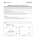
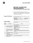
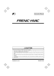
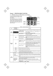
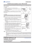
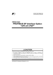
Figure 1 Front of Card
-1-
Figure 2 Back of Card
If you suspect the product is not working properly or if you have any questions about your product, contact your Fuji Electric representative.
(3) The model name "OPC-F1-RS" is printed on the RS485 Communications Card. (See Figure 1.)
(2) The RS485 Communications Card has not been damaged during transportation--no defective electronic devices, dents, or warp.
(1) An RS485 Communications Card is contained in the package.
1. Check that:
Modbus RTU protocol. For details, refer to the RS485 Communications User's Manual (MEH448a or later).
Two communication protocols are available for the RS485 Communications Card: Fuji general-purpose inverter protocol and the
The RS485 Communications Card can be connected neither to a keypad nor to PC loader.
This feature allows you to connect your FRENIC-Eco to host equipment such as a personal computer or PLC, so that the FRENIC-Eco can
be treated as a device subordinate to the host.
• Control from host equipment
Thank you for purchasing the RS485 Communications Card OPC-F1-RS. Installing this card on your FRENIC-Eco series of inverters
enables RS485 communication (via the RJ45 port for communication with a keypad) on the inverter plus the following expanded feature:
RS485 Communications Card "OPC-F1-RS"
Installation Manual
Figure 4 Mounting Communications Card
-2-
INR-SI47-0872
Figure 5 Mounting Completed
Fuji Electric FA Components & Systems Co., Ltd.
Figure 3 In the case of
FRN7.5F1S-2J thru
FRN15F1S-2J
capacities of 37 kW or above, close also the keypad enclosure.
To put back the converter cover, refer to Section 2.3 "Wiring" of FRENIC-Eco Instruction Manual (INR-SI47-0882-E). For
(5) Put the cover back to the inverter.
For details of cabling, refer to RS485 Communications User's Manual (MEH448a or later).
(4) Connect the associated cables between the OPC-F1-RS and the network.
Visually check that the spacers and CN1 are firmly inserted (See Figure 5.).
(3) Insert the four spacers and CN1 on the back of the OPC-F1-RS into the four spacer holes and Port A (CN4) on the control circuit
board in the inverter (See Figure 4.).
capacities of 37 kW or above, open also the keypad enclosure.
To remove the inverter cover, refer to Section 2.3 "Wiring" of FRENIC-Eco Instruction Manual (INR-SI47-0882-E). For
(2) Remove the cover from the inverter and expose the control circuit board (See Figure 3.).
(1) If more than one inverter is connected in your network and you are going to install the RS485 Communications Card on the
inverter at the network end, then be sure to turn SW103 (switch for connecting/disconnecting the terminating resistor) (shown in
Figure 1) to the ON position. The factory default is OFF.
Otherwise, electric shock could occur.
Turn the power off and wait for at least five minutes for models of 30 kW or below, or ten minutes for models of 37 kW or above, before
starting installation. Further, check that the LED monitor is unlit, and check the DC link circuit voltage between the P (+) and N (-)
terminals to be lower than 25 VDC.
2. Installation