1
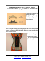
MCM Backpack Model BP-1 User’s Guide
User’s Guide
MCM Backpack
Model BP-1
Part # 12715
Thank You!
The M. C. Miller Co., Inc., would like to take this opportunity to thank you for the purchase of the
MCM Backpack Model BP-1. We trust you will find its use in your Cathodic Protection work
helpful to you and that it increases the efficiency of your efforts.
This User Manual will provide you with the necessary information and instructions regarding the
Backpack. Should you have any additional questions regarding the Backpack and its use, please
contact MCM for assistance.
There is a comment sheet in the back of this manual. After you have worked with the Backpack
for a while and when you have time, please fill out the sheet, and return it to M. C. Miller Co., Inc.
We are always interested in hearing from the people who work with our products everyday.
M. C. Miller Co. Inc,
M. C. Miller Co., Inc.
11640 US Hwy 1
Sebastian, FL 32958
772-794-9448
Fax: 772-589-9072
[email protected]
www.mcmiller.com
Revised: August 19, 2011
11640 US Hwy #1~ Sebastian ~ Florida ~ 32958
www.mcmiller.com ~ [email protected]
Instruments and Software for the Corrosion Engineer
2
Table of Contents
Subject
Page Number
Backpack - General Information
4
Backpack - Assembly Procedure
4
Backpack - Fitting the Backpack to
the User
5
Backpack - Using the Model BP-1
Backpack
6
Installation Instruction for Gx
Mounting Brackets (Optional)
7
The Data Probe – Preparation for Use
10
The Data Probe – Instructions for Use –
Direct Read One Probe Only
11
The Data Probe – Instructions for Use –
Direct Read Two Probes
11
The Data Probe – Instructions for Use –
Continuous Read One Probe Only
12
The Data Probe – Instructions for Use –
Continuous Read Two Probes
12
Continuous Read Trigger for the Gx
10
For All Data Probes
13
How to Hook up Connections for CIS
Surveys
13
Automatic Triggering Option
15
Figure 1
16
Parts Lists
17
11640 US Hwy #1~ Sebastian ~ Florida ~ 32958
www.mcmiller.com ~ [email protected]
Instruments and Software for the Corrosion Engineer
3
Assembling and Using the Model BP-1 Backpack
General Information
The Model BP-1 Backpack unit is a premium quality all-weather mountaineering
pack frame to which has been added a meter table, wire spool platform (with
room for a spare reel), and an optional wire-measuring device. A separate data
probe with an electrode and a built-in push button switch (MCM Part# SIN015)
used to manually enter a reading into a data logger such as the MCM G1 and the
Gx version.
The Backpack is designed for comfortable use by individuals whose height is 5‟9”
(1.7 meters) or more. Customized adjustment is accomplished by straps and by
coin slot adjusting screws.
The Backpack meter table is designed for the Gx data logger. However, the
table is large enough making it adaptable for use with other meters as needed.
A meter table designed for the Allegro, SinCorder, Sin2, and G1 are available
upon special order. Contact MCM at [email protected] or 772-794-9448 for
more information.
The Backpack is shipped in a single sturdy cardboard carton. A small amount of
final assembly is needed to make the Backpack ready for use. It should take the
user about fifteen minutes and requires only a medium-sized flathead and a
philips screwdriver plus an ordinary pair of pliers.
Assembly Procedure
(See Figure 1 located on page 11 of this manual for additional assistance.)
11640 US Hwy #1~ Sebastian ~ Florida ~ 32958
www.mcmiller.com ~ [email protected]
Instruments and Software for the Corrosion Engineer
4
1. Open one end of the cardboard shipping container and slide out
the Backpack.
2. Remove the 11” X 13” Meter Table which is temporarily secured by
bag ties to the Backpack. Install the Meter Table onto the
Platform Arm Assembly.
3. Adjust the forward/backward position of the Meter Table using the
Platform Locking Knob, located on the Platform Arm Assembly. The
angle of the Meter Table may be adjusted using the two lock knobs,
located under the Meter Table.
Fitting the Backpack to the User
There are several adjustments, which will tailor the Backpack to fit a particular
user. The following will assist you to achieve the best fit for the user.
Note: It is recommended, but not necessary to have someone assist the user in
this process so as to decrease the amount of time to make the proper fitting.
1. Using a flathead screwdriver or coin, loosen both adjustable fittings on the
shoulder Cross Bar (Figure 1:A).
2. Loosen the Backpack Strap (Figure 1:E) until the pads slide up and down
on the frame.
3. Hoist the Backpack to your back by grabbing the top bar from underneath
with one hand. Note: You may wish to first hoist the Backpack to the top
of your right thigh, resting it there … just above the knee. Grab the pack
with your left hand and slide your right arm through the shoulder strap.
Hoist the Backpack onto your back. Insert your left arm through the left
shoulder strap.
4. Adjust the Padded Waist Belt (Figure 1:N) and Shoulder Straps (Figure
1:D) making sure that the Backpack is snug and secure. Note: The
position of the shoulder level crossbar should be directly opposite or
slightly above the cervical bone located at the base of the user‟s neck. If
this is not the case, move the adjustable fittings up or down by following
“a” or “b” below or both. Once in the correct position, tighten the fittings.
a. Padded Waist Belt: Position the Padded Waist Belt by adjusting
the two vertical gray straps causing the band to move either up or
down. Adjust as needed to fit the user. The padded waist belt
should be fitted directly around the user‟s waist. This provides the
greatest degree of comfort while walking.
b. Upper Padded Back Band: Position the Upper Padded Back Band
by adjusting the two horizontal gray straps causing the band to
move either up or down. Adjust as needed to fit the user.
5. Adjust the width of the shoulder straps for the greatest comfort. Move the
11640 US Hwy #1~ Sebastian ~ Florida ~ 32958
www.mcmiller.com ~ [email protected]
Instruments and Software for the Corrosion Engineer
5
pad to the outside set of holes if the pads touch the user‟s neck. Do Not
over tighten the nuts and bolts; one thread showing past the nylon insert
locks them. Leave enough play for the pads to swivel slightly.
6. Using the waist suspension system allows the user to transfer the weight
from their shoulders and back to their waist. The Backpack is adjustable
from the bottom up, providing maximum variability. It also increases the
ability to transfer and adjust the load, helping to prevent unnecessary back
and shoulder fatigue.
Using the Model BP-1 Backpack
The Backpack is especially useful for Close Interval Surveys (CIS) because the
adjustable Meter Table may be adapted by the user to accept a variety of data
loggers, indicating meters, or even a strip-chart recorder.
The following suggested procedures assume that the user has the optional
footage counter and data probe accessories. Should the user not have either or
both accessories, the user may skip the steps that refer to them.
1. Adjust the Backpack to fit the user wearing it.
2. Remove the Terminal Post Assembly (Figure 1:F). To do this, unscrew
the white plastic base from the Spool Post.
3. Slide a spool of #30 wire onto the Spool Post (Figure 1:G). Make sure
the pigtail wire from the Hub is on the upper side. Replace the Terminal
Post Assembly.
4. Using a pocketknife or sandpaper, remove the enamel insulation from at
least 1” of both the inner and outer ends of the #30 wire. Extra Caution
should be used in order to not break the pigtail lead.
5. Insert the inner end of the wire into the BLACK (negative) terminal post
located on the top of the Spool Post. Turn the Terminal Nut (Figure 1:B)
until it “snugs up” onto the wire. Do Not over tighten, as damage to the
inner wire will occur.
6. Unscrew the Captive Wire-threading Needle (Figure 1:C) from the right
side of the wire measure. Push it straight down … through the fairleader
spring (Figure 1:H) on the top of the Wire Measurer. Thread the outer
end of the #30 wire through the eye of needle. Pull the needle back up
out of the Wire Measurer. This insures that the wire is properly situated
within the Wire Measurer.
7. Mount the Gx meter to the Meter Table supplied with the Backpack. The
Meter Table includes the Digital Counter (MCM Part# SUB420).
a. The Meter Table should be removed from the bar it is attached to
by releasing the bar from the Meter Table via the two black knobs.
Removing the Meter Table is not required, but you will find it easier
to mount the Gx if you do.
11640 US Hwy #1~ Sebastian ~ Florida ~ 32958
www.mcmiller.com ~ [email protected]
Instruments and Software for the Corrosion Engineer
6
Installation Instructions for Gx Mounting Brackets
(Gx Bracket Kit: Catalog # 11273 – To integrate a Gx Data-logger with a
Gx Platform)
The mounting brackets (Top
Bracket and Bottom
Bracket) are supplied with
their hardware (screws &
spacers) pre-installed, as
shown opposite.
Step 1: Place the Gx data-logger front-side down on a clean, flat surface and
remove the four screws highlighted in the photograph shown opposite using
a flat-head screwdriver.
Next, remove the hand
strap and associated
brackets from the unit.
This will reveal 4 tapped
holes (two on the top and
two on the bottom).
11640 US Hwy #1~ Sebastian ~ Florida ~ 32958
www.mcmiller.com ~ [email protected]
Instruments and Software for the Corrosion Engineer
7
Step 2: Line up the Top
Bracket screws with the top
two tapped holes, as shown in
the photograph opposite, and
secure the Top Bracket using
a Phillips-head screwdriver.
Note: Do not over-tighten
the screws so as not to strip
the threads.
Step 3: Line up the Bottom Bracket with the bottom two tapped holes, as
shown in the photograph
opposite, and secure the
Bottom Bracket using a
Phillips-head screwdriver.
Note: Do not over-tighten
the screws so as not to strip
the threads. Also, make sure
that the flat washers are in
place.
Step 4: If required, adjust the
position of each ball bearing
on the Bottom Bracket, using
a flat-head screwdriver as
indicated in the photograph
opposite, for a best fit with
the corresponding bracket on
the Gx Platform.
11640 US Hwy #1~ Sebastian ~ Florida ~ 32958
www.mcmiller.com ~ [email protected]
Instruments and Software for the Corrosion Engineer
8
The Gx has two brackets top and bottom.
b. The Back-Pack meter table also
has to matting Bracket on it. Both
will match to clip on for easy on
and easy removal. There are
adjustment screws you can adjust
to make the brackets fit tighter or
looser to your comfort.
c. Reattach the Gx to the Platform.
d. Reattach the Meter Table to the
aluminum bar.
8. Attach the appropriate Data Probe and related wiring as described in the
section of this manual titled The Data Probe. Go to this section now and
then return here once the Data Probe(s) is attached.
9. A spare spool of #30 wire may be mounted on the lower end of the Spool
Post should you anticipate using all the wire on the main spool during the
testing period.
10. Pull several feet of the wire up through the Wire Measurer, insuring that
the wire is feeding easily. Reset the Counter back to 0 (zero) or a black
screen by pushing the RED button.
11. Attach the bare end of the wire to the terminal of the test station or test
point. Make sure there will be no strain on the connection.
12. Make descriptive entries into the meter in order to later identify the survey.
These entries should provide the answers to the questions of „who,‟ „what,‟
„when,‟ and „where.‟
13. After making sure that all the meter switches are in the correct position,
begin the survey. Take readings at regular intervals as indicated by the
Wire Measurer‟s display.
14. MCM suggests that the used wire be removed from the test site daily.
This avoids any potential nuisance to property owners and animals.
WARNING:
The Wire Measurer is calibrated for use ONLY with special #30 and #34 wire.
The use of any other size or type of wire will seriously affect the accuracy of the
Wire Measurer. The #30 wire recommended for use with the Model BP-1
Backpack is available from M. C. Miller Co., Inc. on spools of a single and
continuous length of approximately five miles. #34 wire is available in 1 mile and
3 mile spools.
The wire Should Be removed from the Wire Measurer at the end of the survey in
order to prevent the neoprene measuring wheel from taking a “set” which will
cause the slippage of wire when the Wire Measurer is used next.
11640 US Hwy #1~ Sebastian ~ Florida ~ 32958
www.mcmiller.com ~ [email protected]
Instruments and Software for the Corrosion Engineer
9
The Data Probe
Preparation for Use
Data Probes do not come with the Backpack. If a data probe is ordered and
used with the Backpack, the following information will explain the proper setup
and use of the probe.
Note: There are different data probes available for use. The following
instructions will include the variables in the set up for each type. Be sure you
know the type of probe you are using and whether you will be taking positive or
negative survey readings.
As received, the electrode on the Data Probe will contain no liquid. There is,
however, a quantity of blue-copper sulfate crystals in the orange plastic tube.
1. To prepare the electrode for use (*SEE WARNING on Page 11), unscrew
the porous plug assembly from the bottom of the tube and fill the tube with
distilled water or MCM’s Electrode Anti-Freeze Solution (MCM Part#
17105 or 17207).
2. Replace the porous plug assembly and tighten firmly so as to effectively
seal the tube. Try to avoid getting crystals on the threaded portion of
the tube.
3. Shake the tube a few times to insure a saturated solution is created as
soon as possible. The solution will be blue in color and there should
always be some undissolved copper-sulfate crystals at the bottom of
the tube.
4. After filling, allow at least five minutes for the porous plug to wet up before
using the probe. It is normal for the porous plug to leak slightly until the
pressure within the tube equalizes with atmospheric pressure.
5. MCM recommends that the protective cap be left off the electrode for the
first two hours after the water has been added. The initial leakage, which
may occur, is corrosive to many metals and should not be allowed to seep
into any test equipment. When the leakage stops, the protective cap
should be kept on the plug whenever the probe is not actually in use.
11640 US Hwy #1~ Sebastian ~ Florida ~ 32958
www.mcmiller.com ~ [email protected]
Instruments and Software for the Corrosion Engineer
10
Instructions for Use
Using the Gx Data Probe (MCM Part# SIN015)
Direct Read to the Gx – One Probe Only
1. Choose the Positive or Negative Coiled Data Probe Cable (depending on
whether you will be taking Positive or Negative readings).
2. Take the Male end of the cable and attach it to the Gx port. The cable will
fit only one port of the Gx and it is keyed to that port. Do Not force the
cable to attach.
3. Mount the Meter Table to the Backpack (assuming it is not already
attached) by sliding to aluminum pole attached to the Meter Table into the
appropriate slot on the lower right side of the Backpack. Secure it by
tightening the black knob.
4. Take the Black coiled cord from the Backpack and attach the end to the
Counter attached to the Meter Table. You will find it helpful to wrap the
cord around the metal pole of the table to help keep the cord from
catching onto brush etc. as you take the survey.
5. Depending on which Coiled Data Probe Cable you use (Positive or
Negative), take the Positive (Red) or Negative (Black) straight cord with
the stacked banana plugs (supplied with the Backpack) and attach one
end to the Digital Counter and the other end to the banana jack of the Gx
(Red for Positive or Black for Negative).
6. Attach the female end of the Coiled Data Probe Cord to the Data Probe.
Using the Gx Data Probe (MCM Part# SIN015)
Direct Read to the Gx – Two Probes
1. Locate the Dual Data Probe Adapter (MCM Part# SIN017), located on the
underside of the Meter Table.
2. Attach the male end of cord running from the Dual Data Probe Adapter to
the Gx port. The cable will fit only one port of the Gx and it is keyed to that
port. Do Not force the cable to attach.
3. Attach both coiled Data Probe cables (Positive or Negative) to the Dual
Data Probe Adapter (one cables to each connection).
4. Mount the Meter Table to the Backpack (assuming it is not already
attached) by sliding to aluminum pole attached to the Meter Table into the
appropriate slot on the lower right side of the Backpack. Secure it by
tightening the black knob.
5. Take the Black coiled cord from the Backpack and attach the end to the
Digital Counter attached to the Meter Table. You will find it helpful to wrap
the cord around the metal pole of the table to help keep the cord from
catching onto brush etc. as you take the survey.
6. Depending on which Coiled Data Probe Cable you use (Positive or
Negative) take the Positive (Red) or Negative (Black) straight cord with the
11640 US Hwy #1~ Sebastian ~ Florida ~ 32958
www.mcmiller.com ~ [email protected]
Instruments and Software for the Corrosion Engineer
11
stacked banana plugs (supplied with the Backpack) and attach one end to
the Counter and the other end to the banana jack of the Gx (Red for
Positive or Black for Negative).
7. Attach the female end of each coiled Data Probe Cord to the Data Probe.
Using the Data Probe (MCM Part# TRI014)
Continuous Read with the Gx - One Probe Only
1. The Gx should already be attached to the Meter Table. The Backpack
should be already attached to the Meter Table and Counter.
2. Using the Continuous Read Data Probe, insert the cord from the probe
into the appropriate banana plug receptacle of the Gx (Negative if taking
negative reads or Positive for taking positive reads).
3. Depending on which type of reading you will be taking (Positive or
Negative), take the Positive (Red) or Negative (Black) straight cord with
the stacked banana plugs (supplied with the Backpack) and attach one
end to the Counter and the other end to the open banana jack of the Gx.
Using the Data Probe (MCM Part# TRI014)
Continuous Read with the Gx - Two Probes
1. The Gx should already be attached to the Meter Table. The Backpack
should be already attached to the Meter Table and Counter.
2. Using the Continuous Read Data Probes, insert the cord from the first
probe into the appropriate banana plug receptacle of the Gx (Negative if
taking negative reads or Positive for taking positive reads).
3. Using the second probe, insert its cord into the top of the stackable
banana jack of the first data probe. Depending on which type of reading
you will be taking (Positive or Negative), take the Positive (Red) or
Negative (Black) straight cord with the stacked banana plugs (supplied
with the Backpack) and attach one end to the Counter and the other end
to the open banana jack of the Gx.
Continuous Read Trigger for the Gx
The Backpack and its Counter will allow automatic triggering of reads as the
user walks along the route of the survey. As the user travels every 2.5 feet,
the Counter triggers (an audible beep is heard) and a reading is transmitted
from the data probe to the Gx at that moment.
11640 US Hwy #1~ Sebastian ~ Florida ~ 32958
www.mcmiller.com ~ [email protected]
Instruments and Software for the Corrosion Engineer
12
This is accomplished by attaching the Trigger Cable (MCM# SIN024) from
the Counter to the Gx.
1. Take the Trigger Cable and screw one end into the appropriate terminal of
the Gx. The coupling allows the cable to only attach one way. Do not
force the cable onto the Gx.
2. Attach the other end of the Trigger Cable to the positive and negative
terminals located on the underside of the Meter Table. The terminals are
two #Phillips head screws (one marked (+) and the other marked (-). The
Trigger Cable end has two terminals, RED for positive and BLACK for
negative. Note: care should be taken to insert each terminal end between
the screw head and the washer. This assures and strong contact.
For All Data Probes
1. Remove the ORANGE protective cap from the porous plug.
2. Insert the Data Probe‟s DIN connector carefully into the “Trigger” Port.
This port is located on the same side as the input terminals. The DIN and
the BLACK release button on it should face up. Properly inserted, the
DIN connector will snap into place and lock. To remove, press the
BLACK button and pull out gently.
3. Place the porous plug into contact with the earth. Press the RED button
on the Data Probe handle. This causes the Gx to take readings.
(This
assumes that the Gx is in one of its trigger modes and has been activated
(indicated by a blinking “L” in the upper left hand corner of the display).
Refer to the Gx manual for additional information.
* WARNING: DO NOT unscrew the WHITE plastic cap and copper-rod assembly
from the aluminum tube. Doing so will cause internal wiring to twist and break.
How to Hook Up Data-Probe Cables and make final Backpack Connections
for CIS Surveys
1. Turn the data-probe platform upside down and connect the two MCM
black-band cables (assuming that you will be measuring normally negative
pipe-to-soil readings) to the dual-probe adapter unit mounted on the
underside of the data-logger platform.
2. Assuming that your data-logger is mounted on the top side of the datalogger platform and that the output cable of the dual-probe adapter has
been connected to the 5-pin terminal on the data-logger, mount the datalogger platform to the Backpack, by sliding the platform arm assembly into
the appropriate slot on the lower right side of the Backpack. Secure it by
tightening the black knob.
3. Connect the black coiled cable from the Backpack to the counter/display
11640 US Hwy #1~ Sebastian ~ Florida ~ 32958
www.mcmiller.com ~ [email protected]
Instruments and Software for the Corrosion Engineer
13
unit mounted on the data-logger platform. You will find it helpful to wrap
the cord around the metal pole to help keep the cord from catching onto
brush etc. as you perform the survey.
4. Connect the short (red) banana plug cable between the counter/display
unit and the red banana plug terminal on the data-logger (again, assuming
normally negative pipe-to-soil readings will be recorded).
5. Finally, connect the other ends of the data-probe cables to the redhandled and the green handled data-probes. These MCM data-probes
have push-button switches that allow the user to manually-trigger
readings.
The configuration described above is illustrated in Figure 2 below. This
configuration is used for the case of manually-triggered readings (see your datalogger‟s User‟s Manual or the CIS Training Manual for details) using the pushbutton switches on the data-probes.
Figure 2
11640 US Hwy #1~ Sebastian ~ Florida ~ 32958
www.mcmiller.com ~ [email protected]
Instruments and Software for the Corrosion Engineer
14
Automatic Triggering Option
The Backpack is supplied with an automatic trigger cable that can be used to
trigger readings automatically each time 2.5 feet (or 1 meter in the metric option
case) of trail wire is fed through the wire measurer. For this option, which is
illustrated in Figure 3 below, the trigger cable is connected to the 5-pin terminal
on the data-logger and the MCM data-probe cables are not used. Note: The
banana plug cables shown in Figure 3 (to the data-probes) are supplied by the
customer.
Figure 3
11640 US Hwy #1~ Sebastian ~ Florida ~ 32958
www.mcmiller.com ~ [email protected]
Instruments and Software for the Corrosion Engineer
15
Figure 1
Parts Lists
The following are key parts to the Backpack and may be used as a guide for
ordering replacement parts as needed.
11640 US Hwy #1~ Sebastian ~ Florida ~ 32958
www.mcmiller.com ~ [email protected]
Instruments and Software for the Corrosion Engineer
16
Backpack Table with Cables – Part # SIN065 (Combined Unit as Shown
Below)
A
B
C
D
E
F
G
2
2
2
1
2
1
1
1
Part # HAR295
Part # HAR330
Part # HAR303
Part # SIN017
Part # KNO015
Part # PAN075/A
Part # SUB420
Part # SIN026
1 Part # SIN024
#10 x1/2” Long Nylon Spacer
10-32 x 1 ¾” Philips FL Head
10-32 Nylon Lock Screw
Sin2 Dual Data Probe Adapter
Knob Table BP-1
Backpack Front Panel
Audible Display (USA)
Backpack Red and Black Test Lead (Not
Shown)
Trigger Cable (Not Shown)
11640 US Hwy #1~ Sebastian ~ Florida ~ 32958
www.mcmiller.com ~ [email protected]
Instruments and Software for the Corrosion Engineer
17
Backpack Spool Table – Part # SIN067 (Combined Unit as Shown Below)
A
B
C
D
E
F
1
1
1
1
1
1
Part # HIP030
Part # SUB440
Part # WIR047
Part # PAN075
Part # WIR057
Part # SUB450
Spool Lock with Terminal
Spool Post Assembly
6” Diameter Rubber Pad
Backpack Spool Table
Quick Release Pin
Spool Post Frame Assembly
11640 US Hwy #1~ Sebastian ~ Florida ~ 32958
www.mcmiller.com ~ [email protected]
Instruments and Software for the Corrosion Engineer
18