1
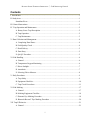
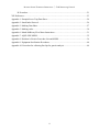
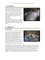
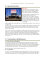
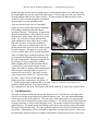
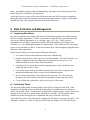
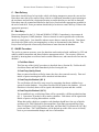
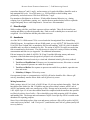
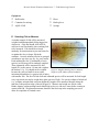
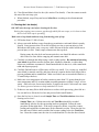
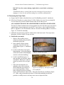
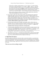
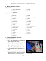
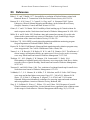
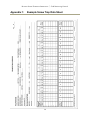
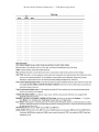
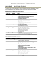
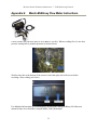
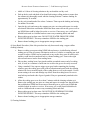
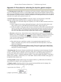
Rotary Screw Trapping Operational Protocol A Detailed Protocol for Rotary Screw Trapping Field Operations for the Stanislaus River Prepared for: U. S. Fish & Wildlife Service Prepared by: Cramer Fish Sciences Revised September 2014 Copyright © 2014 by Cramer Fish Sciences Suggested citation: Cramer Fish Sciences (CFS). 2014. Rotary Screw Trapping Operational Protocol – A Detailed Protocol for Rotary Screw Trapping Field Operations for the Stanislaus River. Prepared for the U.S. Fish and Wildlife Service. 44 pp. ROTARY SCREW TRAPPING OPERATIONS Field Monitoring Protocol Contents I. Introduction ............................................................................................................................... 1 II. Study Area................................................................................................................................ 1 Stanislaus River ................................................................................................................. 1 III. General Instructions ................................................................................................................ 2 IV. Trap Operation and Maintenance............................................................................................. 2 A. Rotary Screw Trap Description ..................................................................................... 2 B. Trap Operation .............................................................................................................. 2 C. Trap Maintenance ......................................................................................................... 3 V. Data Collection and Management ............................................................................................. 4 A. Completing Data Sheets ................................................................................................ 4 B. Field Quality Check ...................................................................................................... 4 C. Data Delivery ................................................................................................................ 5 D. Data Entry .................................................................................................................... 5 E. QA/QC Procedure ......................................................................................................... 5 VI. Fish Handling .......................................................................................................................... 6 A. General ......................................................................................................................... 6 B. Temperature/Oxygen Monitoring .................................................................................. 6 C. Direct Sunlight .............................................................................................................. 7 D. Anesthesia .................................................................................................................... 7 E. Selecting Fish to Measure .............................................................................................. 8 V. Daily Procedures ...................................................................................................................... 9 A. Trap Safety ................................................................................................................... 9 B. Equipment Checklist ..................................................................................................... 10 C. Trap Check Procedures ................................................................................................. 11 VI. Fish Marking ........................................................................................................................... 17 A. General ......................................................................................................................... 17 B. Marking Equipment Checklist ....................................................................................... 18 C. Photonic Dye Marking Procedure .................................................................................. 18 D. Bismarck Brown Y Dye Marking Procedure ................................................................. 20 VII. Trap Efficiencies .................................................................................................................... 21 A. General ......................................................................................................................... 21 i ROTARY SCREW TRAPPING OPERATIONS Field Monitoring Protocol B. Procedure ...................................................................................................................... 21 XII. References ............................................................................................................................. 23 Appendix 1: Example Screw Trap Data Sheet ............................................................................... 24 Appendix 2: Smolt Index Protocol ................................................................................................ 26 Appendix 3: Marking Data Sheet .................................................................................................. 27 Appendix 5: Marking codes .......................................................................................................... 30 Appendix 6: Marsh-McBirney Flow Meter Instructions ................................................................. 31 Appendix 7: AQUI-S20E MSDS ................................................................................................... 32 Appendix 8: Davidson’s Fixative Procedure List and MSDS ......................................................... 36 Appendix 9: Equipment Sterilization Procedures ........................................................................... 40 Appendix 10. Procedure for collecting fin clips for genetic analysis .............................................. 44 ii ROTARY SCREW TRAPPING OPERATIONS Field Monitoring Protocol I. Introduction The following protocol gives detailed procedures for the daily operation of a rotary screw trap (RST) (Figure 1), including trap operation and maintenance, fish handling and marking, data collection and management, and trap efficiency estimates. Protocols were developed to provide detailed information to make field activities as safe as possible and to collect accurate and unbiased data. Reference List For additional information, please see Tsumura and Hume 1986, Thedinga et al. 1994, Nickelson 1998, Miller and Sadro 2005, Bottom et al. 2005, Volkhardt et al. 2007, Tattam et al. 2013, among others. Figure 1. Technician cleaning rotary screw trap cone. II. Study Area Stanislaus River The Caswell study site is located on the Stanislaus River (RM 8.6) at Caswell Memorial State Park. This site was selected in 1995 and juvenile Chinook salmon out-migration data have been collected there every year since then. The trapping site is located approximately 10 to 50 m upstream of the park boundary depending upon river conditions. The Caswell traps are configured in a side-by-side pattern (Figure 2). We access our trapping site by a private levee road (Brocchini’s property). We have established Figure 2. North and south Caswell traps. landowner agreements as well as a permit from California State Parks to operate and access the traps. The Stanislaus River, like all San Joaquin River tributaries, is regulated by dams (e.g., Goodwin, Tulloch, New Melones) and diverted by canals and agricultural pumps for city and agriculture uses. Typically, the average flow on the Stanislaus River is 300 ft3/s during a dry year; 1,000 ft3/s during a moderate year; and 3,000 ft 3/s during a wet year. Other research activities on the Stanislaus River include, rotary screw trapping at Oakdale Recreation Area, California Department of Fish and Wildlife (CDFW) carcass surveys, and adult escapement monitoring at the Stanislaus weir. Gravel augmentation and juvenile habitat restoration projects are on-going. 1 ROTARY SCREW TRAPPING OPERATIONS Field Monitoring Protocol III. General Instructions Safety first! Safety should always be your primary concern. Never perform a task if it cannot be performed safely. Stay aware of your surroundings and possible hazards at all times. Make suggestions about improvements to safety procedures to your partner in the field or the Project Lead. Figure 3. Warning sign on a rotary screw trap. A minimum of two crew members will operate the trap at any time. At least one crew member must have a working cell phone when in the field. All crew members will document they have read and understood the job hazard analysis (JHA) for screw trapping. LIFE-JACKETS ARE TO BE WORN AT ALL TIMES WHILE IN A BOAT, ON A TRAP, OR IN THE RIVER. First aid kits, emergency road flares, and fire extinguishers will be maintained in all vehicles and boats. Be cautious to always keep hands, loose clothing, and other items away from the cone, shaft and other moving parts during trap operation. Never remove debris from cone or shaft while the trap is rotating. Rotary screw traps and associated rigging are a possible hazard to boaters, swimmers and others using the river. Wires and cables should be marked with bright colored flagging and buoys to be easily seen. Warning signs should be positioned both upstream and downstream of traps to instruct boaters how to avoid the trap. Other protective measures may include flashing lights to improve trap visibility and deflectors to prevent river users and large woody debris from entering trap (Figure 3). IV. Trap Operation and Maintenance A. Rotary Screw Trap Description Screw traps are widely used to trap out-migrating salmon and steelhead. Their catch can be combined with trap efficiency tests to estimate the total number of out-migrants leaving the system. Rotary screw traps consist of a cone, supported on two pontoons, with interior baffles to trap and transfer fish to a live-box (see Figures 1-4). Rotary screw traps are manufactured by E.G. Solutions in Corvallis, Oregon. Traps are usually positioned in the main flow or river thalweg and angled to catch the maximum amount of flow. B. Trap Operation The cone is lowered into fishing position with a single hand winch. Always be cautious when lowering the cone. Keep a hand on the winch crank handle until the cone is in place, make sure the latch is free, and slowly lower the cone. When raising the cone, keep a hand on the winch crank 2 ROTARY SCREW TRAPPING OPERATIONS Field Monitoring Protocol handle and make sure the latch is caught in gear securely (latches tend to wear, and if not secure, the winch handle may spin too quickly and cause injury). The forward end of the cone should be lowered until the shaft is at the water’s surface. The trap counter (Redington stroke counter model W1-2936) records the number of rotations the trap spins in a given sampling period. Traps are checked once a day at a minimum (Figure 4), but as often as necessary to maintain a safe holding condition for fish and efficient operation of the trap. The frequency of trap checks depends on the number of fish collected, level of instream flow, debris loads, and objectives of the study. The collection of larger fish may bias catch abundances as they tend to prey on small fish in the live-box. To provide a predation refuge, a milk crate, or similar object, may be placed upside down in the live-box with a weight on top to anchor it. The purpose is to provide Figure 4. Technician performing a trap check. access to smaller fish, such as juvenile salmonids while excluding larger, potential predacious fish. It is important to ensure that the screen/mesh of the crate is appropriate. Hard objects should also be sedentary as to not crush fish by shifting. When sampling fall-run Chinook salmon in the Central Valley, trap operation begins in early winter (December or January) and continues until daily average water temperatures exceed 22°C (usually late June or July). Once daily average water temperatures exceed 22° C the traps must be raised. Traps can be lowered and begin fishing again once temperatures drop below 22° C. If water temperature conditions allow, the trap Figure 5.Technician inspecting the cone. should be fished until June 30 to ensure that any late outmigrants are detected. The Project Lead has the authority to either fish or pull the traps. C. Trap Maintenance The traps are inspected daily for damage and improper wear. The field crew will inspect the live-box seal for any cracks and proper seating around the cone. The cone shaft and bushings will be inspected for cracks and wear. The cone mesh will be inspected for any tears and the access doors will be inspected for proper closure (Figure 5). The winch system will be inspected for proper function, as well as cable and pulley wear. The counter system will be inspected for proper function. The anchor points and cabling system for the traps will be inspected for faults. The traps will be cleaned daily. The cone, pontoons, and live-box will all be scrubbed and free from debris. Maintenance will be performed as inspections warrant such activities. Please note all maintenance performed and trap condition on datasheets and notify the Project Lead of any 3 ROTARY SCREW TRAPPING OPERATIONS Field Monitoring Protocol issues. If problems cannot be addressed immediately, take photos to document the issue and contact the Project Lead before leaving the site. At the end of the year, traps will be removed from the river and will be pressure washed and thoroughly inspected for any damage as well as possible improvements. Repairs will be made and then the traps will be properly stored until the next field season. V. Data Collection and Management A. Completing Data Sheets Data sheets should be clear, legible, and contain all information needed to accurately interpret data (see example, Appendix 1). If there is more than one data sheet for a particular site, make sure they are labeled appropriately (e.g., site name, page 1 of 2, etc.). Please make all information clear enough so someone not familiar with field conditions can interpret data accurately (i.e., use standard abbreviations, no omitted data). There should never be any empty spaces for relevant data on a sheet. If data are not taken, draw a line through the appropriate box and write a short explanation. Please use the following conventions when filling out data sheets: 1. Use a pencil, and your best and clearest non-cursive handwriting. 2. Organize the data sheet so like species are recorded together. Look at catch before you begin recording data and leave ample space to group data for each species. Use additional sheets to assure clarity of the information. 3. Completely fill out the top block and the appropriate gear section, include the crew names and data recorder’s name. 4. Corrections can be made in the field by erasing if the sheet is dry, or putting a line through the mistake and clearly writing correct information nearby. 5. Never estimate information. Record measured values only. If a value cannot be measured, put a line in the box and make an explanation in the comments section. 6. Circle all dead fish on data sheet. Do not circle any live fish counts. B. Field Quality Check The first step of data quality assurance/quality check (QA/QC) happens in the field. After completion of sampling, review the data sheet and make sure all information is complete, or collect any missing values. Common errors include blanks, illegible entries, clarity of plus count tallying, incorrect species or station codes, and unclear comments. The field quality check should occur before leaving the site so additional data can be collected if necessary. This is the first of four checks that must be completed for the data to be properly QA/QC’d. The other three are done as, or after, the data are entered into the computer (see Section E below). 4 ROTARY SCREW TRAPPING OPERATIONS Field Monitoring Protocol C. Data Delivery Data sheets should always be kept in the vehicle cab during transport to ensure they are not lost. Data sheets must always be removed from vehicles or clipboards immediately upon returning to the warehouse and stored in a designated location to ensure that they are not lost or damaged. Data sheets must be scanned and emailed to the Project Lead and other appropriate personnel at the end of each shift. Extra precautions should always be taken to ensure delivery of data to the appropriate person(s). D. Data Entry Data are maintained in the U.S. Fish and Wildlife (USFWS) Comprehensive Assessment & Monitoring Program (CAMP) database. Data are entered as soon as possible after collection, ideally on a daily basis. Care should be taken to assure data are entered correctly. Data sheets also need to be filled out for non-trapping days so they are documented in the database. The Project Lead will provide all necessary instructions to enter data into the database. E. QA/QC Procedure The goal is to generate accurate, error-free data that can be analyzed with confidence by CFS and others to address immediate and future fisheries management needs. The accuracy of data are checked by insuring data are collected and recorded without error, and entered error-free into the database. 1. Field Data Check This first step of the QA/QC procedure is described above (Section B). Field techs will check data sheets and initial immediately before leaving the site. 2. Data Entry Quality Check Data are entered and then verified to insure they have been entered correctly. Date and initials of person entering data will be noted on each data sheet. 3. Data Entry Verification I (QC 1) The verification will check for entry errors by comparing data sheets with hard copy queries from the database. Corrections if needed will be made to the database. As each data sheet is checked, sheets will be signed with initials of person and date verified. 4. Data Entry Verification II (QC 2) The second hard copy verification of data will be repeated by a different technician than QC 1. Corrections, if needed, will be made to database. Data sheets will be signed with initials of person verifying data and date verified. When data quality checks are complete each datasheet should have four sets of initials and dates on it: Field Checked By person and date; Data Entry person and Date, Data Entry Verification I (QC1 By) person and Date, and Data Entry Verification II (QC2 By) person and Date. The CAMP database will be backed up on the office server on a daily basis to prevent unintended changes and loss of information. 5 ROTARY SCREW TRAPPING OPERATIONS Field Monitoring Protocol VI. Fish Handling A. General Fish that you handle are a public resource; therefore, proper care of fish is extremely important. Furthermore, some species captured may be (or become) listed under the federal and/or state Endangered Species Act (ESA); for these species, specific handling protocol may be warranted. In general, care should be taken to ensure all fish are handled properly to reduce stress, injury, and mortality. Fish, especially juvenile salmonids Figure 6. Chinook salmon sac-fry. (Figures 6 and 7), are sensitive to changes in water temperature, dissolved oxygen levels, sunlight and a variety of other factors. All work should take place out of direct sunlight, and care should be taken to ensure cool water temperatures with adequate dissolved oxygen levels are provided. When handling fish, make sure your hands and all surfaces that the fish come into contact with are wet with river water. In general, fish should spend as little time as possible away from their river Figure 7. Chinook salmon fry. environment. Fish should only be handled by trained personnel that have a valid California Scientific Collecting Permit (SCP). When removing from the live-box, be careful not to injure fish between the rim of the scoop net and the wall of the live-box. Live-box corners are typically where fish are injured and killed. Make every effort to chase fish out of live-box corners before netting them. Excess debris in the scoop net can also injure fish and cause fish to be out of water too long while the debris is sorted through on the deck. Chinook fry should be removed using a small net while the scoop net is still submerged and then placed into a separate bucket from other fish to prevent predation and cannibalism. F i g u r e 9 . B. Temperature/Oxygen Monitoring Coolers (ice chests) may be used instead of buckets as insulated walls keep water temperatures lower longer. When using buckets, locate buckets in shade, check holding water temperature regularly and change water or add ice when temperatures are 2°C greater than river water temperature. Lids should always be used to reduce potential jumping, predation or spillage. Use dark colored buckets and lids for holding and transporting fish. When transferring fish between locations (e.g., hauling tank to river, bucket to holding tank, etc.), always check temperature difference between environments. Differences greater than 2°C should be avoided since this change can cause loss of equilibrium and stress. Make sure fish are not over-crowded (i.e., that there are < 25 smolts or < 50 fry per bucket; 100-150 individuals per standard-size cooler). Dissolved oxygen levels should be maintained near current river levels (generally 6 F i r s t C h i n o o k ROTARY SCREW TRAPPING OPERATIONS Field Monitoring Protocol somewhere between 7 and 11 mg/L), and an aerator or O2 tank with diffuser should be used to help maintain DO levels. Use a DO meter (e.g., YSI ProODO) to check holding water periodically, and refresh water if DO level falls below 7 mg/L. Pay attention to fish behavior at all times. If fish exhibit abnormal behavior (e.g., darting, scraping, loss of equilibrium, gasping, etc.), transfer them to another bucket/cooler to replenish oxygen and gently lower water temperatures. Do not leave fish unattended. C. Direct Sunlight While working with fish, avoid their exposure to direct sunlight. This will also benefit your comfort and ability to collect high-quality data. Find or create a shaded place to measure and weigh fish. Cover all buckets and net pens while not in use. D. Anesthesia As of the 2013-14 field season CFS is covered under the Investigational New Animal Drug (INAD) Program. In compliance with our INAD permit, we use AQUI-S® 20E (hereafter AQUIS; AQUI-S New Zealand Ltd.) to anesthetize fish for safe handling. AQUI-S is safe for humans to handle and is an effective anesthetic for fish. The action of AQUI-S is readily reversed when fish are transferred to fresh water. The effectiveness is related to a variety of factors including concentration and fish size (see Appendix 7 for additional information). Fish are immersed in a bath of AQUI-S (20-30 mg/L) and the following sensory and motor responses of the fish characterize progressively deeper levels of anesthesia: 1. Sedation: Decreased reactivity to visual and vibrational stimuli; gill activity reduced. 2. Total Loss of Equilibrium: Fish turns over; locomotion increases; fish swims or extends fins in response to pressure on caudal fin or peduncle. 3. Total Loss of Reflex: No response to pressure on caudal fin or peduncle; opercular rate slow and erratic. 4. Medullary Collapse: Gill activity ceases. Overexposure (in time or concentration) to AQUI-S will lead to death for fish. Observe gill activity; immediately transfer fish to fresh water if gill activity ceases. Mixing Instructions With a syringe, inject 0.5 to 0.6 mL of AQUI-S into 4 L of water and mix thoroughly. Check the knockdown time with a few fish. If fish have not lost reflex within 3 minutes, add 0.1 mL of AQUI-S and monitor with a new small group of fish. Dosage can be increased to a maximum of 1 mL AQUI-S per 4 L of water but sedation should be completed with the smallest dose possible to effectively achieve loss of reflex. Gloves should be worn while preparing AQUI-S solution and handling fish. The dosage and total amount of AQUI-S used per day will be recorded on the datasheets for reporting purposes. Stress Coat, which helps replace slime coat and protect scales on a fish, will be used in AQUI-S water and recovery buckets. Add 2.5 ml per 4 L (small-bucket) and 5 ml in 5 gallons (nearly full recovery bucket). 7 ROTARY SCREW TRAPPING OPERATIONS Field Monitoring Protocol Equipment: Half-bucket Water Container for mixing Nitrile gloves AQUI-S 20E Syringe E. Selecting Fish to Measure A random sample of fish will be measured, weighed, and photographed (following project objectives). A dip net should ALWAYS be used (never use bare hands) when catching fish to be measured. Fish should be selected randomly for measurement to prevent biases for or against the slow or larger fish in the container. Juvenile salmon will also be grouped according to age class (sac-fry, fry, parr, smolt). Each morning the first 25 salmonids (of each species) in each trap will be randomly sampled. These salmonids will be measured for fork length (FL) to the nearest 1.0 mm and weight to the nearest 0.1 g. Fry should not be weighed Figure 8. Diagram showing where to measure because they are too small for an accurate length on a fish without a forked caudal fin. measurement and there is a greater risk of injury with smaller fish. The first 20 fish of all non-salmonid species will be measured for fork length every trap check (no need to weigh these other species of fish). For species without a forked tail (i.e., sculpins, mosquitofish, and some bullhead), length will be measured laterally along the mid-line to the posterior edge of the tail (Figure 8). Measure and weigh one fish at a time. Hands, dipnets, and measuring boards should always be wet with river water before coming in contact with fish. Weight measurements should be the final step in the sampling process to allow for expulsion of retained water. 8 ROTARY SCREW TRAPPING OPERATIONS Field Monitoring Protocol V. Daily Procedures A. Trap Safety Good communication is essential to any working team. Keep open communication between all crewmember and make sure that instructions or other communications are heard and understood. There is nothing wrong with asking questions or requesting that someone repeat what was said. Always wear a life-jacket when working on the trap. Be cautious when moving around on the trap. A number of hazards exist on and around the trap (e.g., winch, cleats, cables, frayed cable, etc.). Stay aware of these hazards and always use great caution when moving and working on traps. NEVER move across the number one crossbeam (in front of the trapping cone) when the trap is fishing. A catwalk on the front of the trap aids in taking flow, clearing cone debris, etc. Always use extreme caution on the catwalk. Pay attention to other crew member locations and activities on the trap, boat traffic and boat wakes, and during high flow conditions watch for large debris that may collide with the trap and have an unexpected effect. All crew members need to pay attention when a boat is approaching and docking at the trap. NEVER place any part of your body between the boat and trap during approach or while moored. The boat operator should drive slowly when approaching the trap and use fenders if available. Crewmembers should be able to step, not jump, from the boat to the pontoon. Make sure fenders are adjusted properly to prevent contact damage to boat or trap. Be very careful when stepping on or off the trap, or walking on the trap. Pontoons and live-box lid may be slippery, due to ice/frost in winter and algal growth in spring/summer. Check winch cable and mooring cables for fraying. Use caution when handling cables to avoid injury to hands. When raising or lowering the cone or live-box door, everyone should be aware and in a safe position. The person changing cone position or opening live-box door should communicate their actions to others and make sure other field technicians have heard them and are aware. When the trapping cone is being lowered, keep hands and feet away from crossbeam when it contacts the pontoon. Always secure the live-box door when in the open position. 9 ROTARY SCREW TRAPPING OPERATIONS Field Monitoring Protocol B. Equipment Checklist Clipboard containing: Data sheets Knife AQUI-S 20E Water sample vials (2) Laminated key code Syringe Pencils/Sharpies Scale sample envelopes Fish ID book Stop watch Thermometer Whirl-packs Surgical scissors Alcohol wipes Toolbox containing: First-aid kit Screw drivers Flashlight Nylon rope Rescue rope Zip ties Pocketknife Dykes Counter bolts/nuts WD-40 Flagging Winch handle Crescent wrenches (2) Other: Paddles Waders Life-jackets Wading boots Park/gate keys Flow meter Ice chest Canoe or inflatable kayaks Digital camera Measuring board 1/2 bucket for AQUI-S Scoop nets (2) Chainsaw (when flows are high) Scrub brushes (2) Dip net (1) Small mesh net (1) Ice 5-gallon buckets (10) with lids Small perforated buckets (for holding fry) Live cars (to hold fish for marking) Photarium 10 ROTARY SCREW TRAPPING OPERATIONS Field Monitoring Protocol C. Trap Check Procedures All bolded text in this section refers to Trap Data Sheet components (Appendix 1). Text in capital letters on datasheet should be recorded each time the trap is checked, and text in lower case must only be recorded during the first trap check of the day. In all cases, if there are any questions about trap load, fish identification, etc. that cannot be answered in the field or with a phone call, always take a photograph with a measuring point of reference (stadia rod, measuring board, etc.) included in the picture. i. Overview a) Record Location, Station, Gear Status, Trap Visit Type, Recorder/Crew, Field Checked By and Date on data sheet. Determine Gear Status to track when traps are raised and lowered and when the trap has been serviced. Gear status code definitions are as follows: 1 = Continue trapping in same position and configuration 2 = Unplanned restart after malfunction (raised cone for maintenance/debris) 3 = End trapping in current position and configuration (raised cone to cease trapping for a given period of time) 4 = Start trap and begin trapping (dropped cone) 5 = Drive by b) Observe trap function and make sure it is operating properly from the shore before boarding the trap. Important: Sometimes it may be necessary to stop the trap or raise the cone to remove debris, depending on debris level this step may need to be performed only after the livebox has been cleared. NEVER reach into a moving cone! c) Record Before Revs prior to boarding trap. BEFORE REVOLUTIONS DO NOT NEED TO BE RECORDED IF TRAP IS STOPPED ON ARRIVAL. Determine revolutions per minute (RPM) as follows: 1. As the screw trap cone spins, find a marker on the cone (i.e., counter bolt) to watch, and use a stopwatch to determine how many seconds it takes the cone to complete three full rotations. 2. Record this value in the appropriate space on the data sheet. d) Board the trap to inspect and determine the Condition Code and record on the data sheet. 11 ROTARY SCREW TRAPPING OPERATIONS Field Monitoring Protocol Condition code describes trap activity during the sampling period and describes an element of variability in trap performance. Condition code definitions are as follows: 1 Good Indicates the trap is fishing and operating well (normal) 2 Fair Describes situations resulting in partial cell blockage, but water and fish are still delivered to the live-box (e.g., partial cell block) 3 Malfunction Trap is not functioning because of a stopped cone, or both cells are blocked. e) Scrub and clean exterior of cone, pontoons, and live-box with a brush. f) Record the Gauge Height and measure the Water Temperature, Dissolved Oxygen (D.O.), Velocity, and take a Turbidity sample; record values on the data sheet. Gauge Height Gauge height will be measured to the nearest 0.02 ft and recorded at each trap check. Water Temperature and Dissolved Oxygen Dissolved oxygen is a function of water temperature (i.e., lower temperature water has a higher capacity to hold dissolved oxygen); therefore, both temperature and dissolved oxygen affect salmon survival. Measure the water temperature (°C) and dissolved oxygen (mg/L and %) values during each trap check using a digital handheld meter (e.g., YSI Environmental, Inc.; Model 550A or ProODO). Submerge the probe in at least 0.5 m of water and wait until a stable reading is obtained. Record the reading in the appropriate space on the data sheet. Water Velocity Measure the average water velocity in front of each screw trap using a flowmeter (e.g., Marsh-McBirney Flowmate 2000), approximately halfway between the right pontoon and the cone shaft and 0.5 m below the waters surface; record value on the corresponding data sheet. Make sure the flow meter is using m/s. Refer to Appendix 6 for more information about the use and maintenance of the flow meter. Turbidity Collect a water sample and use a portable turbidimeter (e.g., Hach 2100P) to measure the current turbidity level NTU) and record the value in the appropriate location on the data sheet. Collect water in a clean glass vial. Refer to the unit's user manual for more information about proper use, calibration and maintenance of the turbidimeter. g) Record Debris Level Debris levels are estimated using the following as a rough guideline: Light: less than one 10 gallon tub Medium: 1–3, 10 gallon tubs Heavy: 4–6, 10 gallon tubs Very heavy: Greater than six 10 gallon tubs 12 ROTARY SCREW TRAPPING OPERATIONS Field Monitoring Protocol h) Clear fish and debris from live-box (See section 2 for details). Clear the counter to mark the start of the next trap cycle. i) When finished, step off trap and record After Revs according to the aforementioned procedure. ii. Cleaning the Live-box(es) DO NOT raise the trap cone before cleaning the live-box. Raising the trapping cone creates a gap through which fish can escape, so it is best to clean the live-box while trap is operating. Make sure to keep hands and nets away from moving parts of trap. a) Fill bucket about 1/2 full of water. b) Always start with shallow scoops from the top to minimize catch until debris is mostly cleared. Scoop no more than 1/4 net full of debris at a time to prevent injury to fish. With the net still in the water, scoop any visible fish out of the net with a smaller net to prevent injury to fish. Gently empty contents onto the trap deck. During sunny days the deck can become quite hot, care should be taken to cool the deck with river water before emptying net contents onto deck. c) Carefully sort through the debris using a stick (or other probe). Be cautious when using your hands; hypodermic needles, broken glass, blackberry branches, or other sharp objects are sometimes encountered. Return natural debris to the river; collect man-made trash and dispose properly. d) Carefully find and remove all fish (some will be very small). Use a scoop (e.g. modified water bottle) to transfer small fry and place them in a separate bucket from larger fish to prevent predation and/or cannibalism. Make sure fish are not overcrowded in buckets (< 25 small fish per bucket). e) Make sure water temperature in bucket remains no more than 2°C greater than the river water temperature and D.O. remains within acceptable parameters (within 1.0 mg/L of river water). Add cool water, frozen water bottles, or replace the water if it becomes too warm. Use battery powered aerators to help maintain D.O. levels. f) If there are too many fish to hold in buckets or coolers while processing, place fish in a live-car and leave fish in the live-box and process fish in small batches. g) Once the live-box is cleared, record Sample Time and Total Revolutions when done clearing out live-box*. Sample Time (on a 24-hour timescale) and Total Revs should be recorded immediately after the live-box processing has been completed. Follow the same procedure for the night check. If the trap is stopped by debris, record the counter reading and explain the circumstances in the comments section. Then clear the livebox and cone of debris and record the final counter reading below the Total Revs box. Reset the counter once the time is recorded and the live-box has been cleared. 13 ROTARY SCREW TRAPPING OPERATIONS Field Monitoring Protocol DO NOT clear the counter during a night check, second check, or during a release *If additional debris is cleared from cone after clearing the live-box due to a stoppage, re-clear live-box of debris taking care to look for additional fish. iii. Processing the Trap Catch a) Prepare AQUI-S bath as described above (see Fish Handling section D. Anesthesia) b) Fill at least 2 buckets (or coolers) about 3/4 full of fresh river water for recovering fish. Use one bucket for juvenile Chinook and the other for all other species. ALL SAMPLE FISH MUST BE ANESTHETIZED TO WEIGH AND MEASURE. The first 25 Chinook salmon from each trap and the first 20 of all other species need to be sampled unless water temperature exceeds 20°C (see below). Also record Smolt Index (SI; see Appendix 2) for all salmonids collected. Record Gill Rating (GR; see Section d, Figure 13) if fish look unhealthy. c) Add fish to be measured to AQUI-S solution after it has been tested. Do not put more than about 10 fish in AQUI-S at any one time. d) Fish Health Assessment i. Observe fish carefully prior to sedation to identify any potentially moribund (dying) fish. ii. Once sedated, look for lesions, commonly across the back in a saddle shape (Figure 9; ‘saddleback lesion’). iii. Look for indications of pin-point hemorrhaging, or for hemorrhaging at fin bases (careful, hemorrhaging can also result from handling). Figure 9. Example of a ‘saddleback lesion’ on a fish infected with Columnaris. iv. Look for small black spots (~2 mm) anywhere on the body, which can indicate ‘Black spot’ a disease caused by parasitic larvae (Figure 10). v. If the fish is determined to be unhealthy, place fish on dorsum (back) and gently press down on Figure 10. Example of ‘black spot’ disease jaw to open operculum, a blunt on a caudal fin. probe can also be used, to carefully expose gill filaments for observation. Note gill color and rate accordingly (Figure 11). (Note: only perform this procedure if a fish looks unhealthy because the procedure is mildly invasive and may cause stress or injure the fish.) 14 ROTARY SCREW TRAPPING OPERATIONS Field Monitoring Protocol vi. Moribund fish should be placed into a whirl-pack labeled with the fish species, date, trap location, and crew members. The whirl-pack should be delivered to the USFWS Fish Health Center or be placed on ice until it can be processed. IMPORTANT: immediately call the Project Lead to report moribund fish observations or the incidence of any of the above symptoms. DO NOT release any fish at this time; prepare to be advised for potential further action. CDFW will be informed immediately and consulted for further action. It may be imperative to mort and fix specimens immediately (Appendix 8), be sure to have fixing agents and equipment for preservation available on site. Time is of the essence and fish need to be preserved promptly. Figure 11. Gill Rating (GR) color scale ranging from 1 = pale to 5 = deep red. e) Determine Smolt Index (SI) and Gill Rating (GR), and measure FL (mm) and weight to the nearest 0.1 g (WT) for each salmonid and record these values on the data sheet. f) ALWAYS check juvenile Chinook salmon for marks every trap check. Check for marks as fish are being measured, or use a plexiglass viewer (if available) for fish not measured. g) Photograph the 1st, 10th, and 20th salmonid of each species. Also, photograph any other fish of special interest (different morphology, disease, condition, etc.), representative specimens from the sample, or fish for which specific identification is uncertain. More photos are better than not enough. You only have one opportunity to take a photo. Photograph fish after all other information has been collected. The plexiglass viewer (if available) can be used for more realistic photos, and works well for capturing fin details, especially for unidentifiable species. Following photograph, place fish in recovery bucket then photograph the datasheet with a pencil pointing to the data for fish just photographed (Figure 12). On the backside of the data form in the ‘Photo Log’ record the Fish #. For salmonids, record Species Code (e.g., CHN) followed by a dash then the data cell number (i.e., row by column number: CHN-01; Figure 12). For non-salmonids record ‘Species Code’ (e.g., PL for Pacific Lamprey) 15 Figure 12. Datasheet photo shot of salmonid data. Figure 13. Datasheet photo shot of incidental species data. ROTARY SCREW TRAPPING OPERATIONS Field Monitoring Protocol followed by a dash then column number (e.g., PL-2; Figure 13). In this example, other entries would include SASU-1, PL-1, PRS-1, MQK-1, and LP-1. Also, take note of the total number of photos taken for each sample (not including datasheet photo shot) and record value in # of Photos column. Specific notes are not required, but should be recorded if additional information is warranted; attempt to relate specific notes to individual photos. Upon returning to the office, download and label photos with the following naming convention: YEAR-MONTH-DAY-SPECIES CODE-FISH NUMBER (eg. 2011-02-21-CHN-01). h) Scale samples will be taken from Chinook salmon and steelhead smolts sampled for length and weight (if scales are developed); no more than 50 Chinook salmon scale samples should be collected per week (10 samples per day). Scale samples are collected using a clean pocketknife to gently scrape a few scales from the “scale pocket” (i.e., behind the dorsal fin above the lateral line). The scales are then wiped onto a piece of waterproof paper and placed into a labeled coin envelope. Fill in the envelope label with the Date, Station (location), Species, SI, FL and WT. i) Fin clips (tissue samples) and (if feasible) scale samples will be collected from any anomalous fish (e.g. yearlings, non-fall run Chinook, steelhead smolts). These samples should be stored in envelopes and labeled as described in Appendix 10. Report any anomalous fish to the Project Lead before releasing them. i) Count the number of individuals of each species that exceeds the number measured, and record value in the Plus Count column associated with that species. Record plus counts by lifestage when possible. If water temperature exceeds 20°C, do not take any measurements but record all fish as “plus counts”. If water temperatures exceed 22°C do not handle fish – pull live-box screen and let all fish and debris flush out. j) After fish have recovered (i.e., swimming and reacting normally), salmonids and incidental fish may be released separately at pre-designated locations well downstream from the traps. Never release fish directly from or upstream of the traps. iv. Night Check Procedures In general, night checks follow the same procedures as day checks with the exception that the cone is not cleaned and the counter is not reset unless there is a blockage that is preventing the cone from rotating freely. The counter should always be reset after clearing the cone. Data that needs to be collected during a night check, and for all trap checks, is indicated on the data sheet by all caps. Take extra care when working at night! 16 ROTARY SCREW TRAPPING OPERATIONS Field Monitoring Protocol VI. Fish Marking A. General Fish are marked utilizing commonly accepted marking techniques as described for other markrecapture studies (e.g., Baker and Modde 1977; Gaines and Martin 2004, Bottom et al. 2005, Miller and Sadro 2005, Rayton 2006). The purpose of marking and releasing fish is to determine the efficiency of the trap, and an assumption of this technique is that marked fish behave similarly to natural fish in the system. Therefore, it is essential that fish are minimally and gently handled and are kept in water that is within 2°C of river water so that they experience as little stress as possible during marking, transport, and release. First, fish can be marked with photonic dye using a needless injector that places a small, semipermanent dye mark between fin rays (Figure 14). Photonic dye marks are usually placed on the caudal fin for fry-size fish; however, the dorsal and anal fins can also be marked when fish are larger than 45 mm. Photonic dye marks may last for several days to several weeks. Figure 14. Chinook salmon fry marked with a pink dye on the caudal fin (CFP). Figure 15. Sub-yearling smolt marked by immersion in Bismarck Brown Y solution. Note: mark is most prominent and visible around the mouth, operculum and on the ventral fins (i.e., pectoral, pelvic and anal), especially when compared with unmarked fish. A second marking method is by immersion, using Bismarck Brown Y (Sigma-Aldrich, Inc.) in solution, to produce a whole body mark (Figure 17). Prominent brownish coloration around the mouth, operculum, and on the ventral fins (i.e., pectoral, pelvic and anal) distinguish fish dyed by immersion in Bismarck Brown Y solution. The whole body dye generally only lasts a few days (e.g., 3 to 5 d); however, fish used for trap efficiencies typically pass the trap after only 1 to 3 days. Bismarck Brown Y is typically only used when large numbers of fish are released. 17 ROTARY SCREW TRAPPING OPERATIONS Field Monitoring Protocol B. Marking Equipment Checklist Clipboard with: AQUI-S 20E solution Syringe Data sheets Pencils Thermometer Extra seals Aerator Marine grease Nylon rope for net pens Alcohol Waders Toothbrush Wading boots Dye powder Ice chests Inoculators Card table Towels Chairs Dye and syringe Large bottle of water Half-bucket(s) Latex gloves 3–5 Buckets Spade Dip net Toolbox Scoop net Net pen Canopy Photarium Stress coat Toolbox with: C. Photonic Dye Marking Procedure 1. Set up your location. a) Set up work station (Figure 16) including table, chairs and canopy (not shown). b) Start a new Marking Data Sheet (Appendix 3) and record: Date: Project Location; Crew; Observers (if present); Origin of Stock; Release Code; Mark Applied (Appendix 5); Holding Temp; Holding DO; and Start Time. c) Connect marking gun to a regulator on a CO2 tank. d) Attach marking dye hose and place the end of the hose in pure water. Run pure water through the gun to make sure it is working properly. 18 Figure 16. Typical set-up for dye marking Chinook salmon. ROTARY SCREW TRAPPING OPERATIONS Field Monitoring Protocol e) If working properly, remove the hose from the pure water container and place in the marking dye container. Note: marking dye is 1 part marking paint to 1 part purified water mixed thoroughly. f) Open all keys on marking gun and shoot marking dye though a few times to make sure it is working properly. Then close all but one key and fire gun a few times. Adjust regulator pressure to ~300 psi and make sure it is still firing properly. g) Use a wet plastic cutting board as a marking surface. h) Fill a cooler half full of water, attach aerator or O2 diffuser, add StressCoat (see ‘Mixing Instructions’ above) and up to 150 fish at a time, depending on size. i) Mix AQUI-S as described above in half-bucket. j) Fill recovery buckets about 2/3 full and add Stress Coat and an aerator. A cooler can be used to recover fish, but when transferring fish to a live-car always use a bucket with a lid. k) Place about 20 fish per marking station in the AQUI-S knockdown half-bucket after it has been tested. 2. Start marking a) Measure FL and determine SI; record values on backside of Fish Marking Data Sheet and place fish on plastic cutting board one at a time for marking. Repeat this step for the first 50 fish (50 fish per Lot sampled if hatchery fish are selected from multiple Lots; note Lot # and Total from Lot on datasheet). b) Apply the mark by starting with only one key open on the marking gun. Lightly place the gun tip onto the appropriate fin and pull the trigger. Be careful, do not place tip and mark too close to the body or fin margin (see Figure 14 for proper mark placement). Do not hold the gun at a right angle to the fin. Adjust the CO2 regulator to approximately 250 psi for fry and 300 psi for parr and smolt. If fin splits when marked, adjust gun pressure or position. c) Count marked fish and place in recovery bucket; tally on data sheet (Mark Tally; note number of fish per tally mark). Use a hand counter to keep track of marked fish. Always check to ensure fish are recovering normally and have visible marks. d) If the gun malfunctions, remove fish from AQUI-S before trying to fix it. Guns can usually be fixed by running 1:1 purified water and Madicide through it, or by reversing the tip. NEVER run river water through the guns…they will clog! If this does not solve the problem after a few attempts, try using a different tip. In between every 100 fish, increase the pressure, open the keys, and blow out the tip to avoid clogs. Shake the dye bottle in between fish groups. e) When approximately 25-50 marked fish, depending on size, have accumulated in the recovery buckets, transfer fish to a live-car in the river. f) After 100 fish have been marked mix new (and test) AQUI-S in 1/2 bucket to minimize biological waste in the water and to help regulate water temperature and D.O. levels. 19 ROTARY SCREW TRAPPING OPERATIONS Field Monitoring Protocol g) After all fish have been marked, record your End Time and the total number of fish marked on your data sheet. Mortalities should be recorded on datasheet and subtracted from total count. (Note: Save all natural mortalities; it is a condition of our Scientific Collecting Permits!) h) After all fish have been transferred to the river, use a permanent marker and some flagging to label the live-car with date, mark applied, number of fish, and expected release date. 3. Clean up a) Carefully position live-car, seal closed with zip ties, and tie off to the bank. Review date, mark applied and number marked on the flagging for correctness. Ensure the live-cars are placed where they will not be stranded or washed away with a change in flows. b) Attach live-car to secure location (e.g., back of trap). Tie off so the water surface is about 1-2 inches below the underside of the plastic rim. c) Clean and load up all supplies. Marking guns should be cleaned thoroughly with clean water and full-strength Madicide. NEVER put a gun back into its case with dye in it. NEVER clean marking equipment with river water d) Field check (QC) data sheet(s) for completeness and correctness. e) Return all supplies to storage; open and let any wet equipment dry out f) Make sure equipment is clean and ready to be used during the next marking event. D. Bismarck Brown Y Dye Marking Procedure 1. Prepare solution (21 mg/L) a) Fill a large tub/tote with 75 L water (approximately 20 gal). b) Measure out 1.6 g Bismarck Brown Y. c) Thoroughly mix Bismarck Brown Y. d) Place aerator and thermometer in tub. Keep water well oxygenated; use ice to maintain water temperatures. 2. Immerse fish a) Count out fish to be dyed with Bismarck Brown Y and place into dye solution. DO NOT anesthetize fish prior to immersion in dye solution. b) Record number of fish, time and temperature on data sheet. c) Set lid over tub to prevent fish from escaping and to protect fish from direct sunlight. d) Observe water temperature and fish activity regularly (every 5 to 10 minutes). e) Gently stir water while observing fish. Fish will initially behave erratically and appear sluggish while in solution. 20 ROTARY SCREW TRAPPING OPERATIONS Field Monitoring Protocol f) Immediately remove individual fish displaying prolonged abnormal behavior and place into well-aerated recovery water. 3. Remove fish a) Remove fish from solution after a minimum of 50 min in solution. b) Immediately place fish in cool, well-aerated recovery water. c) Record end time. VII. Trap Efficiencies A. General Trap efficiency is affected by river stage, flow, environmental conditions, trap placement, life stage and species of fish. Population abundance of juvenile outmigrants can be estimated using the trap-efficiency method of releasing marked fish upstream of each trap (Thedinga et al. 1994, Zeug et al. 2014). When catch numbers are low efficiency estimates are limited by the available number of fish for marking. A minimum of 25 marked fish should be released at a time. Each size-class of juvenile Chinook (sac-fry, fry, parr, smolt) is treated separately as the efficiency of the trap is known to differ by fish size. Measuring trap efficiency as often as possible minimizes experimental bias in estimates which can cause over- or underestimations of population abundance. When possible, marked fish are released in small groups across the entire width of the river channel to aid in uniform mixing of unmarked and marked fish. Thedinga et al. (1994) determined marked fish released at standard release sites were uniformly mixed with unmarked population when river side was alternated. Fish are released at night to minimize predation and maximize movement. After the pre-release check, marked fish will be released for trap efficiency estimates. Night crew will monitor the trap after release to ensure collection and record of marked fish (avoiding the possibility that predation pressure within the trap, or trap stoppage will affect the recapture number). B. Procedure 1. Check marked fish to determine mark retention and mortality a) Fill buckets 1/2 full of water and retrieve fish marked by morning crew. b) Check each fish for a mark using a plexiglass viewer. Count the number of fish with visible marks, the number of fish with no marks, and the number of mortalities for the first 50 fish. Record these values on the Experimental Release Data Sheet (Appendix 4). If any fish from the first batch of 50 are unmarked, check 50 additional fish and update the datasheet. Fish without visible marks MUST be released BELOW the trap as they will not be used in efficiency test and could be confused for wild fish if not marked otherwise. 2. Pre-release trap check a) Traps must be checked and cleared before releasing marked fish. 21 ROTARY SCREW TRAPPING OPERATIONS Field Monitoring Protocol 3. Release marked fish upstream of trap a) Marked fish will be released upstream of trap at the predetermined release site, and then the crew will monitor the trap to determine number of marked fish recaptured. b) Fish will be released when dark, after the trap has been processed (i.e., note ‘prerelease trap check’ in the comments on the Trap Data Sheet). A standard release site will be used for all releases. Small groups of fish (i.e., 5-10) should be released evenly across the channel using a long-handled net, with an inflatable kayak, or by wading if flow is low. The location or side of the river where fish are released should be recorded on data sheet. c) Avoid the use of lanterns or other lights as fish are released (i.e., if possible to do so safely). Avoid running boat between release point and the trap after release has begun. If a boat is used to release fish and must travel downstream after release, remain 15 min at the release point after release and float or row downstream. d) At the time of release, make sure the following are known and recorded on the Experimental Release Data Sheet (see Appendix 4): Release Date and Time, Water Temperature, Number of Fish to be Released, Number of Mortalities, and Mark Color (or type). e) Once all fish have been released record the End Time on the data sheet. f) Wait one hour from the end time before the first check after the release. 4. Check live-box for recapture of marked fish NEVER pull the traps over to access them during a release! a) After 1 hour, clean live-box according to the evening check procedure. Record and process all fish collected by usual procedure and record on Trap Data Sheet. Carefully check all juvenile Chinook salmon for marks. Record fork length (FL) of all marked fish collected. Note in comments ‘1 st post-release trap check’. b) Wait another hour and conduct a second trap check. Note in comments ‘2nd postrelease trap check’. c) If >1% of the release group is recaptured after the second check, wait an additional hour and check trap again. Continue following these guidelines until hourly recapture rates are <1%. d) Any remaining marked fish will be collected during the morning trap check. e) Make sure data sheets are complete and delivered to the Project Assistant as soon as possible. f) Make sure site is clean and no equipment is left behind. 22 ROTARY SCREW TRAPPING OPERATIONS Field Monitoring Protocol XII. References Baker, J. F., and T. Modde. 1977. Susceptibility to predation of blacktail shiners stained with Bismarck Brown Y. Transactions of the American Fisheries Society 106:334-338. Bottom, D. L., K. K. Jones, T. J. Cornwell, A. Gray, and C. A. Simenstad. 2005. Upriver Linkages to Chinook Salmon Migration and Residency in the Salmon River Estuary (Oregon). Estuarine, Coastal, and Shelf Science 64:79-93. Gaines, P. C. and C. D. Martin. 2004. Feasibility of dual-marking age-0 Chinook salmon for mark-recapture studies. North American Journal of Fisheries Management 24:1456-1459. Miller, B. A. and S. Sadro. 2003. Residence time and seasonal movements of juvenile coho salmon in the ecotone and lower estuary of Winchester Creek, South Slough, Oregon. Transactions of the American Fisheries Society 132:546-559. Nickelson, T.E. 1998. ODFW coastal salmonid population and habitat monitoring program. Oregon Department of Fish and Wildlife. Salem, OR. Rayton, M. D. 2006. Field Manual: Okanogan Basin monitoring and evaluation program rotary screw trap protocols. The Colville Confederated Tribes. Omak, WA. Tattam, I. A., J. R. Ruzycki, P. B. Bayley, H. W. Li, and G. R. Giannico. 2013. The influence of release strategy and migration history on capture rate of Oncorhynchus mykiss in a rotary screw trap. North American Journal of Fisheries Management 33:237-244. Thedinga, J. F., M. L. Murphy, S. W. Johnson, J. M. Lorenz and K. V. Koski. 1994. Determination of salmonid smolt yield with rotary-screw traps in the Situk River, Alaska, to predict effects of glacial flooding. North American Journal of Fisheries Management 14:837-851. Tsumura, K., and J.M.B. Hume. 1986. Two variations of a salmonid smolt trap for small rivers. North American Journal of Fisheries Management 6:272-276. Volkhardt, G. C., S. L. Johnson, B. A. Miller, T. E. Nickelson, and D. E. Seiler. 2007. Rotary screw traps and inclined plane screen traps. Pages 235 – 266 in D. H. Johnson, B. M. Shrier, J. S. O’Neal, J. A. Knutzen, X. Augerot, T. A. O’Neil, and T. N. Pearsons. Salmonid field protocols handbook: techniques for assessing status and trends in salmon and trout populations. American Fisheries Society, Bethesda, MD. Zeug, S. C., Sellheim, K., Watry, C., Wikert, J. D., and J. Merz. 2014. Response of juvenile Chinook salmon to managed flow: lessons learned from a population at the southern extent of their range in North America. Fisheries Management and Ecology 21(2): 155-168. 23 ROTARY SCREW TRAPPING OPERATIONS Field Monitoring Protocol Appendix 1: Example Screw Trap Data Sheet 24 ROTARY SCREW TRAPPING OPERATIONS Field Monitoring Protocol 25 ROTARY SCREW TRAPPING OPERATIONS Field Monitoring Protocol Appendix 2: Smolt Index Protocol The Smolt Index is to determine the life stage of salmonids, including Chinook and rainbow trout/steelhead. Smolt Index should be recorded for each fish measured and weighed. Rainbow Trout/Steelhead Smolt Index Protocol Smolt Index Life Stage Criteria 1 Yolk-sac Fry Newly emerged with visible yolk sac 2 Fry Recently emerged with sac absorbed (button up fry) Seam along mid-ventral line visible Pigmentation undeveloped 3 Parr Seam along mid-ventral line not visible Scales firmly set Darkly pigmented with distinct parr marks No silvery coloration 4 Silvery Parr Parr marks visible but faded Intermediate degree of silvering 5 Smolt Parr marks highly faded or absent Bright silver or nearly white coloration Scales easily shed (deciduous) Black trailing edge on caudal fin More slender body 6 Adult > 300 mm FL If < 300 mm FL, must be extruding eggs or milt Chinook Salmon Smolt Index Protocol Smolt Index Life Stage Criteria 1 Yolk-sac Fry Newly emerged with visible yolk sac 2 Fry Recently emerged with sac absorbed (button up fry) Seam along mid-ventral line visible Pigmentation undeveloped 3 Parr Seam along mid-ventral line not visible Scales firmly set Darkly pigmented with distinct to slightly faded parr marks No to slight silvery coloration 5 Smolt Parr marks highly faded or absent Bright silver or nearly white coloration Scales easily shed (deciduous) Black trailing edge on caudal fin More slender body 26 ROTARY SCREW TRAPPING OPERATIONS Field Monitoring Protocol Appendix 3: Marking Data Sheet 27 ROTARY SCREW TRAPPING OPERATIONS Field Monitoring Protocol 28 ROTARY SCREW TRAPPING OPERATIONS Field Monitoring Protocol Appendix 4: Release Data Sheet 29 ROTARY SCREW TRAPPING OPERATIONS Field Monitoring Protocol Appendix 5: Marking codes Mark Code AFB AFG AFK AFO AFP BB BCB BCG BCK BCO BCP BCY CFB CFDB CFDG CFG CFL CFO CFP CFW CFY DFB DFG DFK DFO LCAP LCF TCB TCG TCK TCO TCP TCY UCAP UCF ULCP Mark Description Anal Fin Blue Anal Fin Green Anal Fin Black Anal Fin Orange Anal Fin Pink Bismark Brown Bottom Caudal Blue Bottom Caudal Green Bottom Caudal Black Bottom Caudal Orange Bottom Caudal Pink Bottom Caudal Yellow Caudal Fin Blue Caudal Fin Alcian Blue Caudal Fin Alician Green Caudal Fin Green Caudal Fin Purple Caudal Fin Orange Caudal Fin Pink Caudal Fin Brown Caudal Fin Yellow Dorsal Fin Blue Dorsal Fin Green Dorsal Fin Black Dorsal Fin Orange Lower Caudal and Anal Pink Lower caudal fin clip Top Caudal Blue Top Caudal Green Top caudal Black Top caudal Orange Top caudal Pink Top caudal Yellow Upper Caudal and Anal Pink Upper caudal fin clip Upper and Lower Caudal Pink 30 ROTARY SCREW TRAPPING OPERATIONS Field Monitoring Protocol Appendix 6: Marsh-McBirney Flow Meter Instructions Check to make sure that flow meter is set to m/s (i.e. not ft/s). When recording flow, be sure that pressure sensing bulb is pointed upstream (as shown below). Wait for timer bar at the bottom of the screen to reach the right side of the screen before recording a flow reading (see below). For additional information or troubleshooting, download the Marsh-McBirney Flo-Mate user manual at http://www.hachflow.com/pdf/Model_2000_Manual.pdf 31 ROTARY SCREW TRAPPING OPERATIONS Field Monitoring Protocol Appendix 7: AQUI-S20E MSDS 32 ROTARY SCREW TRAPPING OPERATIONS Field Monitoring Protocol 33 ROTARY SCREW TRAPPING OPERATIONS Field Monitoring Protocol 34 ROTARY SCREW TRAPPING OPERATIONS Field Monitoring Protocol 35 ROTARY SCREW TRAPPING OPERATIONS Field Monitoring Protocol Appendix 8: Davidson’s Fixative Procedure List and MSDS Read the Material Safety Data Sheet (MSDS) and follow all recommended safety procedures. Begin by putting on all of the necessary safety gear (i.e., goggles, gloves, and apron). Fill out a water proof data label for the specimen to be placed in the jar after completion. Make sure you are in a well-ventilated space. Next, gather all the materials needed to fix the specimen: Davidson’s Fixative Sample jar Fish specimen Scalpel or razor blade Alcohol swab Plastic tray (to work in) Paper towels Take the scalpel and sterilize it using an alcohol swab. Next, carefully cut open the specimen from the vent to just below the jaw (this is to expose the internal organs to the fixative…be sure not to cut anything more than the skin and tissue.) Next, poor the fixative into the sample jar. Place the specimen in the jar (fully submerged). Leave specimen in fixative for 48 hours. Clean up work area and dispose of gloves. After 48 hours, follow the safety guidelines above and remove the specimen from the fixative. Place specimen in another jar with 70% isopropyl alcohol. Thoroughly clean up work area when finished. 36 ROTARY SCREW TRAPPING OPERATIONS Field Monitoring Protocol MATERIAL SAFETY DATA SHEET DAVIDSON'S FIXATIVE Section I—IDENTIFICATION PRODUCT: Davidson's Fixative PRODUCT CODE NO.: 12010 Section II—HAZARDOUS INGREDIENTS COMPOSITION % TLV HAZARD Formaldehyde 7.4% 2 ppm Irritant Acetic acid 10.0% 10 ppm Harmful/toxic Ethyl alcohol 28.2% 1000 ppm Flammable Methyl alcohol 1.4% 200 ppm Flammable, poisonous Petroleum naptha 0.3% 500 ppm Flammable Section III—HEALTH AND FIRST AID INFORMATION INHALATION: Irritation of upper respiratory tract. Bronchitis and bronchopneumonia can result from prolonged exposure. Inflammation of eyelids can occur. Formaldehyde exposure is under investigation. In case of exposure, remove patient to fresh air from contaminated area. If patient is not breathing, apply artificial respiration and, if qualified, administer oxygen. Immediately call a physician. Keep the patient warm. INGESTION: Abdominal pain, unconsciousness, collapse. Poisonous, can damage the central nervous system and internal organs and cause blindness. In all cases, immediately call a physician. Wash out mouth thoroughly with water. If the patient is conscious, give milk or water freely to drink to dilute the chemical, induce vomiting. Repeat. EYE CONTACT: Can cause irritation and eye burns. Immediately call a physician. Rinse the eyes with a gentle stream of water for at least 15 minutes, keeping the eyelids separated. Repeat if pain persists. SKIN CONTACT: Can cause irritation, burns, hardening or tanning of skin, cracking and ulceration, or dermatitis. Wash thoroughly with soap and water. Remove and wash contaminated clothing before re-use. Call a physician. Section IV— PHYSICAL DATA BOILING POINT: n. av. VAPOUR DENSITY (AIR=1): n. av. SOLUBILITY IN WATER: Miscible APPEARANCE AND COLOUR: Clear colorless with an acetic acid odor SPECIFIC GRAVITY: n. av. 37 ROTARY SCREW TRAPPING OPERATIONS Field Monitoring Protocol pH: n. av. Section V - FIRE AND EXPLOSION HAZARDS FLASH POINT: n. av. FLAMMABLE LIMITS IN AIR; % BY VOL. LOWER: n. av. FLAMMABLE LIMITS IN AIR; % BY VOL. UPPER: n. av. FIRE FIGHTING PROCEDURES & PRECAUTIONS: Water spray, dry chemicals, carbon dioxide or vaporizing liquid. Wear self-contained breathing apparatus. FIRE & EXPLOSION HAZARDS: May emit toxic vapors. Section VI - REACTIVITY STABILITY: Stable HAZARDOUS POLYMERIZATION: Will not occur CONDITIONS & MATERIALS TO AVOID: Avoid cool temperatures HAZARDOUS DECOMPOSITION PRODUCTS: Unknown Section VII - EMPLOYEE PROTECTION CONTROL MEASURES: In case of a spill, shut off all possible sources of ignition. Wear gloves and goggles. Dike any liquid to prevent its spread to public water sources. Mop up with plenty of water and treat with dilute ammonia solution. Run to waste diluting greatly with running water. Ventilate the contaminated area well to dispel any vapor. If formaldehyde solution enters sewers or drains inform local authorities. RESPIRATORY PROTECTION: Respirators should be used and for large quantities self contained breathing apparatus should be used. PROTECTIVE CLOTHING: Protective clothing or aprons should be used. Gloves should be used. EYE PROTECTION: Safety goggles should be used. VENTILATION: Use only with adequate ventilation. Local exhaust system or fume cupboard should be used. WASTE DISPOSAL: Pour the liquid in a hole in an open area. Wear a respirator. Ensure disposal method complies with local, provincial and federal regulations governing disposal. Section VIII - REGULATORY CONTROLS DEPT. OF TRANSPORTATION: Regulated under Transport of Dangerous Goods. DOT CLASSIFICATION: Class 8 U.N. 1760 DOT PROPER SHIPPING NAME: CORROSIVE LIQUID, NOS (Formaldehyde solution) OTHER DOT INFORMATION: Packing group III, Limited Quantity 5 L WHMIS CLASSIFICATION: D2A OTHER REGULATORY REQUIREMENT: None 38 ROTARY SCREW TRAPPING OPERATIONS Field Monitoring Protocol Section IX—OTHER INFORMATION High concentrations of vapor inhaled for long periods can cause laryngitis, bronchitis or bronchial pneumonia. Prolonged contact with skin can cause cracking of skin and ulceration, particularly around fingernails. Use in an adequately ventilated area. PREPARED BY: MSDS Department DATE: Update January 10, 2008 39 ROTARY SCREW TRAPPING OPERATIONS Field Monitoring Protocol Appendix 9: Equipment Sterilization Procedures The following procedures for cleaning New Zealand Mud Snail (NZMS) infested wading gear can be followed upon exiting NZMS infested waters. Wading gear should be cleaned prior to leaving the site. If this is not possible then wading gear should be completely sealed inside of a large plastic bag and cleaned before it is used in any other waters. Three different cleaning protocols have been tested and found to be effective using specific cleaning solutions: 1) Freeze Procedure a. Place infected gear in a chest freezer for at least 24 hours. 2) Immersion Procedure a. Remove wading gear upon exiting NZMS infested waters. Avoid allowing infested wading gear to come in contact with interior surfaces of vehicles or camping gear such as tents or trailers. NZMS can be transferred to any surface they come in contact with and they could later be transferred back to cleaned wading gear. Turn waders right side out and remove insoles from wading boots. b. Place waders, wading boots, boot insoles and the streambed contact end of a wading stick, if used, in a container of sufficient size to allow the gear to be completely covered by a cleaning solution. c. Pour sufficient cleaning solution into the container with the infested wading gear to completely cover the gear. It may be necessary to weight down the gear to ensure that it remains immersed in the cleaning solution. d. Allow the wading gear to remain in the cleaning solution for at least 5 minutes. e. Remove wading gear from the cleaning solution one piece at a time and inspect it to make sure that all debris that could harbor NZMS has been removed from the gear as well as any NZMS that could be lodged in cracks or crevices. If necessary, use a stiff plastic bristled brush such as a kitchen brush to remove any remaining debris and mud. f. Rinse wading gear in clean water. DO NOT USE WATERFROM THE NZMS INFESTED SOURCE. This may reintroduce NZMS to the wading gear. g. Return cleaned wading gear to it appropriate storage container. 3) Dry Sack Procedure a. Remove wading gear upon exiting NZMS infested waters. Avoid allowing infested wading gear to come in contact with interior surfaces of vehicles or camping gear such as tents or trailers. NZMS can be transferred to any surface they come in contact with and they could later be transferred back to cleaned wading gear. Turn waders right side out and remove insoles from wading boots. b. Place waders, wading boots, and boot insoles into a dry sack (recommended size: 65 liter). Walking sticks will need to be cleaned separately outside of the dry sack to avoid rupturing the sack. 40 ROTARY SCREW TRAPPING OPERATIONS Field Monitoring Protocol c. Add 8 to 10 liters of cleaning solution to dry sack and the seal dry sack. d. Pick up the dry sack and shake it back and forth using a rolling motion to ensure that the contents are thoroughly coated with the cleaning solution. Continue shaking for approximately 30 seconds. e. Let dry sack sit undisturbed for at least 5 minutes. Then repeat the shaking and mixing for another 30 seconds. f. Open the dry sack and remove the contents one piece at a time and inspect it to make sure that all debris that could harbor NZMS has been removed from the gear as well as any NZMS that could be lodged in cracks or crevices. If necessary, use a stiff plastic bristled brush such as a kitchen brush to remove any remaining debris and mud. g. Rinse wading gear in clean water. DO NOT USE WATER FROM THE NZMS INFESTED SOURCE. This may reintroduce NZMS to the wading gear. h. Return cleaned wading gear to it appropriate storage container. 4) Spray Bottle Procedure (Note: this procedure has only been tested using a copper sulfate cleaning solution). a. Remove wading gear upon exiting NZMS infested waters. Avoid allowing infested wading gear to come in contact with interior surfaces of vehicles or camping gear such as tents or trailers. NZMS can be transferred to any surface they come in contact with and they could later be transferred back to cleaned wading gear. Turn waders right side out and remove insoles from wading boots. b. Place waders, wading boots, boot insoles and the streambed contact end of a wading stick, if used, in a container of sufficient size to allow the gear to be easily accessed. c. Using a standard 1 liter squeeze-trigger type spray bottle containing the cleaning solution, spray the wading gear to the point of saturation and runoff with the cleaning solution. Be sure to treat the inside of the wading boots as well as the outside. Use the stream setting to be sure and dislodge any debris from the wading boots. Be sure to treat both top and under side of gravel guards if they are permanently attached to the waders. d. Allow the wading gear to set for at least 5 minutes with the cleaning solution on it. Remove the wading gear one piece at a time and inspect it to make sure that all debris that could harbor NZMS has been removed from the gear as well as any NZMS that could be lodged in cracks or crevices. If necessary, use a stiff plastic bristled brush such as a kitchen brush to remove any remaining debris and mud. e. Rinse wading gear in clean water. DO NOTUSE WATERFROM THE NZMS INFESTED SOURCE. This may reintroduce NZMS to the wading gear. f. Return cleaned wading gear to it appropriate storage container. 5) Cleaning Solutions. 41 ROTARY SCREW TRAPPING OPERATIONS Field Monitoring Protocol a. Copper sulfate: Dissolve 3.785 grams of copper sulfate pentahydrate crystals (99.1% purity) for each gallon of solution you want to make. This will achieve a concentration of 252 mg/L of copper in the cleaning solution. b. Benzethonium chloride: Dissolve 7.57 grams of benzethonium chloride (97% purity) for each gallon of cleaning solution you want to make. This will achieve a concentration of 1,947 mg/L in the cleaning solution. c. Formula 409@ Disinfectant: Dilute the commercially available solution 1:1 with clean water to achieve the needed concentration for the cleaning solution (i.e. 1 gallon of Formula 409® Disinfectant to 1 gallon of water). 6) Tank Disinfection Procedure a. Use a 200 ppm active chlorine solution b. Determine the percentage of active chlorine in commercial liquid bleach or bleaching powder. 1. For example, the percentage of active chlorine in store bought liquid bleach (initial volume = 5.14 L) is 6%. 2. Calculate initial chlorine concentration: 6% / 100 x 1,000,000 = 60,000 ppm. Conclusion: The concentration of chlorine in store bought liquid is 60,000 ppm. c. Calculate total volume that will be treated with 5.14 L of store bought liquid bleach at a final chlorine concentration of 200 ppm. 1. Example calculation: i. Variables: Initial bleach Volume1 = 5.14 L Initial chlorine Concentrationl = 60,000 ppm Final Volume2 treated = unknown Final chlorine Concentration2 in tank = 200 ppm ii. Equation: Volume1 (Concentration1) = Volume2 (Concentration2) iii. Calculation: 5.14 L (60,000 ppm) = V2 (200 ppm) 308,400 = V2 (200 ppm) 1,542 L = V2 2. Conclusion: One standard store bought container of bleach (5.14L) will treat 1,542 L (407 gallons) at a final chlorine concentration of 200 ppm. 3. Adjust the foregoing calculation according to unknown variables. 42 ROTARY SCREW TRAPPING OPERATIONS Field Monitoring Protocol d. Tank treatment 1. Pour the bleach slowly into the tank, mixing as you pour and then fill the tank up to full capacity with clean water. 2. Let the bleach stand in the tank for 1 hour. Completely empty the tank and rinse thoroughly with clean water. 43 ROTARY SCREW TRAPPING OPERATIONS Field Monitoring Protocol Appendix 10. Procedure for collecting fin clips for genetic analysis 1) Collecting tissue from the fish: Cut a small piece of fin tissue from the caudal (preferred) or adipose fin of a live fish using clean scissors or a scalpel blade. Hands of the collector should be cleaned of mucus and scales between handling fish, and scissors/knife should be rinsed between samples. Tissue size should be at a minimum 5 sq. mm. (see below †), which is about the size of a hole punch. If the fin is too small to collect this size sample, take a portion of a pelvic fin. 2) Transferring tissue to storage container: Each tissue sample is stored separately in individual containers: coin envelopes for dry fin clips, or cryotubes for wet tissues or fin clips. a. Dry fin clips: It is critical that samples be completely dry in order for DNA extraction in the lab to be successful. (1) Label a standard scale envelope (unbleached kraft paper) with all relevant details (date, water body, location, species, individual fish identification number, length, weight, etc.) (2) Air dry the samples on filter paper until all mucus and moisture in the fin has evaporated and the tissue is dry to the touch. Place the fin clip in the envelope and loosely close the envelope. Do not seal the envelope, as air and moisture should be allowed to escape to help the fin sample dry out. Do not rubber-band envelopes together until samples inside are completely dry. b. Wet tissue: Alternatively, collected tissues may be deposited into a preservative-filled (typically DMSO or 95% ethanol) cryotube. It is crucial that wet tissue samples be completely immersed and not exposed to air (vial should be filled to the top). Exposure of alcohol-stored tissue to air can cause cell wall fracturing and loss of DNA into the liquid buffer. A minimum 10:1 ratio of preservative to tissue is desired. (1) Place the fin clip into a small glass or plastic vial containing high strength (80% to 95%) ethanol. The ethanol will preserve the tissue and the DNA at room temperature, so does not need to be refrigerated. (2) Label each vial with a permanent (Sharpie) marker. Ensure each sample can be identified later by including the following information on each label: locality, sample number, collection date, and species. (see below example §). 3) Recording data: The date of collection, detailed locality information (accurate description of locality is critical – include GPS info if possible), collector(s) name, species, subspecies, type of collection (e.g. fin clip), fork length, and sex, should be written on data sheets. Use the following abbreviations for species identity: CAGT = California golden trout, LKGT = Little Kern golden trout, KRRT = Kern River rainbow trout, and RBT = rainbow trout. Use “CAGT/RBT” format to indicate fish that clearly appear to be hybridized with rainbow trout. 4) Storing samples: Samples must be kept out of extreme sun/heat (e.g. dashboards, hot warehouses), especially those in ethanol, as this may damage the DNA. 5) Shipping samples: Repackage dried fin clips separately and attach field notes for shipping. Dry samples can be sent surface mail with no special packaging. † approximate size of fin clip: § sample cryovial label: 44