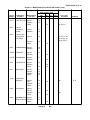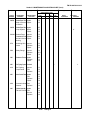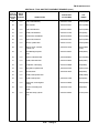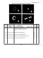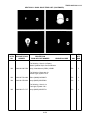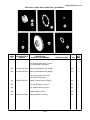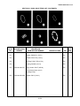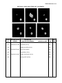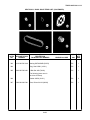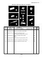
1
TM 55-1905-219-14-12
TECHNICAL MANUAL
OPERATOR, ORGANIZATIONAL, DIRECT
SUPPORT AND GENERAL SUPPORT
MAINTENANCE MANUAL
APPENDIX A
B
REFERENCES
MAINTENANCE
ALLOCATION CHART
C COMPONENTS OF END
ITEMS AND
BASIC ISSUE ITEMS
LANDING CRAFT UTILITY
LCU 1667-1670
NSN 1905-00-168-5764
D
ADDITIONAL
AUTHORIZATION LIST
E
EXPENDABLE
SUPPLIES AND MATERIALS LIST
F
MANUFACTURED
TOOLS
INDEX
HEADQUARTERS,DEPARTMENT OF THE ARMY
8 APRIL 1985
TM 55-1905-219-14-12
C6
CHANGE
HEADQUARTERS
DEPARTMENT OF THE ARMY
WASHINGTON, D.C., 10 October 1996
NO. 6
Operator, Organizational, Direct
Support and General Support
Maintenance Manual
LANDING CRAFT UTILITY
LCU 1667 - 1670
NSN 1905-00-168-5764
DISTRIBUTION STATEMENT A: Approved for public release; distribution is unlimited.
TM 55-1905-219-14-12, 8 April 1985, is changed as follows:
1.
Remove and insert pages as indicated below. New or changed text material is indicated by a
vertical bar in the margin. An illustration change is indicated by a miniature pointing hand.
Remove pages
i/(ii blank)
A-1/(A-2 blank)
C-7 and C-8
-------------------------------
2.
Insert pages
i/(ii blank)
A-1 and A-2
C-7 and C-8
C-8.1/(C-8.2 blank)
C-123/(C-124 blank)
Retain this sheet in front of manual for reference purposes.
By Order of the Secretary of the Army:
DENNIS J. REIMER
General, United States Army
Chief of Staff
Official:
JOEL B. HUDSON
Administrative Assistant to the
Secretary of the Army
02792
DISTRIBUTION:
To be distributed in accordance with DA Form 12-25-E, block no. 1057, requirements for TM 551905-219-14-12.
TM 55-1905-219-14-12
C5
CHANGE
HEADQUARTERS
DEPARTMENT OF THE ARMY
WASHINGTON, D.C., 30 JUNE 1994
NO. 5
Operator, Organizational, Direct Support and General Support
Maintenance Manual
LANDING CRAFT UTILITY
LCU 1667-1670
NSN 1905-00-168-5764
DISTRIBUTION STATEMENT A: Approved for public release; distribution is unlimited.
TM 55-1905-219-14-12, 8 April 1985, is changed as follows:
1.
2.
Remove and insert pages as indicated below. New or changed text material is indicated by a vertical bar in the
margin. An illustration change is indicated by a miniature pointing hand.
Remove pages
Insert pages
i/(ii blank)
B-1 through B-44
C-119/(C-120 blank)
D-7/(D-8 blank)
i/(ii blank)
B-1 through B-44
C-119 through C-122
D-7/(D-8 blank)
Retain this sheet in front of manual for reference purposes.
By Order of the Secretary of the Army:
Official:
GORDON R. SULLIVAN
General, United States Army
Chief of Staff
MILTON H. HAMILTON
Administrative Assistant to the
Secretary of the Army
07110
DISTRIBUTION:
To be distributed in accordance with DA Form 12-25-E, block no. 1057, requirements for TM 55-1905-219-14-12.
TM 55-1905-219-14-12
C4
CHANGE
HEADQUARTERS
DEPARTMENT OF THE ARMY
WASHINGTON, D.C., 31 March 1993
NO. 4
OPERATOR, ORGANIZATIONAL, DIRECT SUPPORT
AND GENERAL SUPPORT MAINTENANCE MANUAL
LANDING CRAFT UTILITY
LCU
NSN
1667-1670
1905-00-168-5764
DISTRIBUTION STATEMENT A: Approved for public release; distribution is unlimited.
TM 55-1905-219-14-12, 8 April 1985, is changed as follows:
1.
2.
Remove and insert pages as indicated below. New or changed text material is indicated by a vertical bar
in the margin. An illustration change is indicated by a miniature pointing hand.
Remove pages
Insert pages
i/(ii blank)
D-7/(D-8 blank)
i/(ii blank)
D-7/(D-8 blank)
Retain this sheet in front of manual for reference purposes.
By Order of the Secretary of the Army:
Official:
GORDON R. SULLIVAN
General, United States Army
Chief of Staff
MILTON H. HAMILTON
Administrative Assistant to the
Secretary of the Army
03961
DISTRIBUTION:
To be distributed in accordance with DA Form 12-25-E, block no. 1057, requirements for TM 55-1905219-14-12.
TM 55-1905-219-14-12
C3
HEADQUARTERS
DEPARTMENT OF THE ARMY
WASHINGTON, D.C., 27 APRIL 1992
CHANGE
NO.
3
Operator's, Organizational, Direct Support
and General Support Maintenance Manual
LANDING CRAFT UTILITY
LCU 1667-1670
NSN 1905-00-168-5764
Approved for public release; distribution is unlimited
TM 55-1905-219-14-12, 8 April 1985, is changed as follows:
1.
Remove and insert pages as indicated below. New or changed text material is indicated by a vertical bar
in the margin. An illustration change is indicated by a miniature pointing hand.
2.
Appendix B, Maintenance Allocation Chart has been changed in its entirety therefore no change
bars are shown.
3.
Remove pages
Insert pages
B-1 through B-36
C-19 through C-22
Index-1 through Index-4
Index-11 through Index-14
Index-19 through Index-22
Index-25 through Index-28
Index-53 and Index-54
Index-57 and Index-58
Index-59/lndex-60
B-1 through B-44
C-19 through C-22
Index-1 through Index-4
Index-11 through Index-14
Index-19 through Index-22
Index-25 through Index-28
Index-53 and Index-54
Index-57 and Index-58
Index-59/lndex-60
Retain this sheet in front of manual for reference purposes.
By Order of the Secretary of the Army:
Official:
GORDON R. SULLIVAN
General, United States Army
Chief of Staff
MILTON H. HAMILTON
Administrative Assistant to the
Secretary of the Army
01014
DISTRIBUTION:
To be distributed in accordance with DA Form 12-25E, (qty rqr block no. 1057)
TM 55-1905-219-14-12
C2
CHANGE
NO. 2
HEADQUARTERS
DEPARTMENT OF THE ARMY
WASHINGTON, D.C.,30 August 1989
}
Operator's, Organizational, Direct Support
and General Support Maintenance Manual
LANDING CRAFT UTILITY
LCU 1667-1670
NSN 1905-00-168-5764
Approved for public release; distribution is unlimited
TM 55-1905-219-14-12, 8 April 1985, is changed as follows:
1. Remove and insert pages as indicated below. New or changed text material is indicated by a vertical
bar in the margin. An illustration change is indicated by a miniature pointing hand.
2.
Remove pages
Insert pages
D-7/D-8
D-7/D-8
Retain this sheet in front of manual for reference purposes.
By Order of the Secretary of the Army:
CARL E. VUONO
General, United States Army
Chief of Staff
Official:
WILLIAM J. MEEHAN, II
Brigadier General, United States Army
The Adjutant General
DISTRIBUTION:
To be distributed in accordance with DA Form 12-25A, Operator, Unit, Direct Support and General Support
Maintenance requirements for Landing Craft, Utility, LUC-1667-1670.
TM 55-1905-219-14-12
C1
CHANGE
No. 1
HEADQUARTERS
DEPARTMENT OF THE ARMY
WASHINGTON, D.C., 11 April 1988
}
Operator, Organizational, Direct Support
and General Support Maintenance Manual
LANDING CRAFT UTILITY
LCU 1667-1670
NSN 1905-00-168-5764
TM 55-1905-219-14-12, 8 April 1985, is changed as follows:
1. Remove and insert pages as indicated below. New or changed text material is indicated by a
vertical bar in the margin. An illustration change is indicated by a miniature pointing hand.
Remove pages
Insert pages
B-17 and B-18
B-35 and B-36
B-17 and B-18
B-35 and B-36
2. Retain this sheet in front of manual for reference purposes.
By Order of the Secretary of the Army:
CARL E. VUONO
General, United States Army
Chief of Staff
Official:
R. L. DILWORTH
Brigadier General, United States Army
The Adjutant General
DISTRIBUTION:
To be distributed in accordance with DA Form 12-25A, Operator, Unit, Direct Support and General Support
Maintenance requirements for Landing Craft, Utility, LUC-1667-1670.
TM 55-1905-219-14-12
CHANGE
HEADQUARTERS
DEPARTMENT OF THE ARMY
WASHINGTON, D.C., 8 April 1985
NO. 55-1905-219-14-12
Operator, Organizational, Direct
Support and General Support
Maintenance Manual
LANDING CRAFT UTILITY
LCU 1667 - 1670
NSN 1905-00-168-5764
REPORTING ERRORS AND RECOMMENDING IMPROVEMENTS
You can help improve this manual. If you find any mistakes, or if you know of a way to improve
these procedures, please let us know. Mail your letter or DA Form 2028 (Recommended Changes
to Publications and Blank Forms), or DA Form 2028-2 located in the back of this manual directly to:
Commander, US Army Aviation and Troop Command, ATTN: AMSAT-I-MP, 4300 Goodfellow
Blvd., St. Louis, MO 63120-1798. You may also submit your recommended changes by E-mail
directly to <mpmt%[email protected]>. A reply will be furnished directly to you.
Instructions for sending an electronic 2028 may be found at the back of this manual immediately
preceding the hard copy 2028.
DISTRIBUTION STATEMENT A: Approved for public release; distribution is unlimited.
TABLE OF CONTENTS
PAGE
APPENDIX A
REFERENCES............................................................................................................... A-1
APPENDIX B
MAINTENANCE ALLOCATION CHART .......................................................................... B-1
APPENDIX C
COMPONENTS OF END ITEM AND BASIC ISSUE ITEMS LISTS ................................... C-1
APPENDIX D
ADDITIONAL AUTHORIZATION LIST............................................................................. D-1
APPENDIX E
EXPENDABLE SUPPLIES AND MATERIALS LIST.......................................................... E-1
APPENDIX F
MANUFACTURED TOOLS ............................................................................................. F-1
INDEX ...................................................................................................................................... INDEX-1
Change 6
i/(ii blank)
TM 55-1905-219-14-12
APPENDIX A
REFERENCES
1.
2.
Fire Protection
TB 5-4200-200-10
Hand Portable Fire Extinguishers for
Army Users
Lubrication
C91001L
3.
Fuels, Lubricants, Oil, and Waxes
Painting
TM 9-213
4.
Painting Instructions for Field Use
Cleaning
C680011
5.
6.
7.
Cleaning and Chemical Products
Maintenance
TM 55-1905-219-20P
Unit Maintenance Repair Parts and
Special Tools List
TM 55-1905-219-34P
Direct Support, and General Support
Maintenance Repair Parts and
Special Tools List
DA Pam 738-750
The Army Maintenance Management System
(TAMMS)
Shipment and Storage
TB 740-244-3
Preservation and Packing of Military Equipment
TB 740-93-2
Preservation of Mechanical Equipment for
Shipment and Storage
Demolition
TM 750-244-3
Destruction of Material to Prevent Enemy Use
Change 6
A-1
TM 55-1905-219-14-12
APPENDIX A
REFERENCES - CONTINUED
8.
Communications, Electronics, Navigation (CEN) Equipment Commercial Manuals
Alden Electronics SATFIND-406 M3 EPIRB
Owner's Manual
Alden TR-IV Marinefax Technical Manual and
Operator's Manual
Instruction Book No.
71261 Rev. C and
Instruction Book
Cat. No. 120 and 122
No. 509754
Belfort Instrument Company Aerovane Indicator
Model 135
Bendix/King EPH/EPI Series Portable Radio
Owner's Manual
Bendix/King EPH Series Portable Radio Service
Manual
Bendix/King LAA Series Battery Chargers
Service Manual
Dymek DA1 OOD All Wave Receiving Antenna
Owner Information Manual
Mackay Communications 403A Emergency
Lifeboat Transceiver Instruction Manual
Naval Electronics Inc. MK22CA/Pba 2205
System Installation and Service Manual
Newmar Heavy Duty DC-DC Converters
Operation and Installation Instructions
RMC Document Number
G261404 Rev A
Raytheon Marine Company Radar Set Model
R40X/R41X AN/SPS-69 Description, Operation
and Maintenance Technical Manual
Ross Engineering DSC 500 Digital Selective Call
Marine VHF Transceiver Operating Manual
TM-8080000701
Sunair Electronics, Inc. Digital Automatic
Antenna Coupler DCU-100 Operation and
Maintenance Manual
A-2
Change 6
TM 55-1905-219-14-12
Appendix B. MAINTENANCE ALLOCATION CHART (MAC)
Section I. INTRODUCTION
B-1
THE ARMY MAINTENANCE SYSTEM MAC.
a
This introduction (Section I) provides a general explanation of all maintenance and repair functions authorized at
various maintenance levels under the standard Army Maintenance System concept.
b
The Maintenance Allocation Chart (MAC) in Section II designates overall authority and responsibility for the
performance of maintenance functions on the identified end item or component. The application of the maintenance
functions to the end item or component will be consistent with the capacities and capabilities of the designated
maintenance levels, which are shown in the MAC in column (4) as:
Unit - includes two subcolumns: C (operator/crew) and O (unit) maintenance.
Direct Support - includes an F subcolumn.
General Support - includes an H subcolumn.
Depot - includes a D subcolumn.
c
Section III lists the tools and test equipment (both special tools and common tools sets) required for each
maintenance function as referenced from Section II.
d
Section IV contains supplemental instructions and explanatory notes for a particular maintenance function as
referenced from Section II.
B-2
MAINTENANCE FUNCTIONS. Maintenance functions will be limited to and defined as follows:
a
Inspect. To determine the serviceability of an item by comparing its physical, mechanical, and/or electrical
characteristics with established standards through examination (i.e., by sight, sound, or feel).
b
Test. To verify serviceability by measuring the mechanical, pneumatic, hydraulic, or electrical characteristics of
an item and comparing those characteristics with prescribed standards.
c
Service. Operations required periodically to keep an item in proper operating condition, i.e., to clean (includes
decontamination, when required), to replace filters, to preserve, to drain, to paint, or to replenish fuel, lubricants,
chemical fluids, or gases.
d
Adjust. To maintain or regulate, within prescribed limits, by bringing into proper or ex- act position, or by setting
the operating characteristics to specified parameters.
e
Align. To adjust specified variable elements of an item to bring about optimum or desired performance.
f
Calibrate. To determine and cause corrections to be made or to be adjusted on instruments or test, measuring,
and diagnostic equipment used in precision measurement. Consists of comparisons of two instruments, one of which is a
certified standard of known accuracy, to detect and adjust any discrepancy in the accuracy of the instrument being
compared.
g
Remove/Install. To remove and install the same item when required to perform service or other maintenance
functions. Install may be the act of emplacing, seating, or fixing into position a spare, repair part, or module (component
or assembly) in a manner to allow the proper functioning of an equipment or system.
H Replace. To remove an unserviceable item and install a serviceable counterpart in its place. Replace is
authorized by the MAC and is shown as the 3rd position code of the SMR code.
Change 5
B-1
TM 55-1905-219-14-12
i
Repair.
The application of maintenance services1 including fault location/troubleshooting2,
removal/installation, and disassembly/assembly3 procedures, and maintenance actions4 to identify troubles and
restore serviceability to an item by correcting specific damage, fault, malfunction, or failure in a part,
subassembly, module (component or assembly), and item, or system.
j
Overhaul. That maintenance effort (service/action) prescribed to restore an item to a completely
serviceable/operational condition as required by maintenance standards in appropriate technical publications
(i.e., DMWR). Overhaul in normally the highest degree of maintenance performed by the Army. Overhaul
does not normally return an item to like new condition.
k
Rebuild. Consists of those service/actions necessary for the restoration of unserviceable equipment to
a like new condition in accordance with original manufacturing standards. Rebuild is the highest degree of
material maintenance applied to Army equipment. The rebuild operation includes the act of returning to zero
those age measurements (hours, miles, etc.) considered in classifying Army equipment and components.
B-3
EXPLANATION OF COLUMNS IN THE MAC, SECTION II
a
Column 1 - Group Number. Column 1 lists functional group code numbers, the purpose of which is to
identify maintenance significant components, assemblies, subassemblies, and modules with the next higher
assembly.
b
Column 2 - Component/Assembly. Column 2 contains the names of components, assemblies,
subassemblies, and modules for which maintenance is authorized.
c
Column 3 - Maintenance Function. Column 3 lists the functions to be performed on the item listed in
column 2. (For detailed explanation of these functions, see paragraph A-2.)
d
Column 4 - Maintenance Category. Column 4 specifies, by the listing of a work time figure in the
appropriate subcolumn(s), the category of maintenance authorized to perform the function listed in Column 3.
This figure represents the active time required to perform that maintenance function at the indicated category
of maintenance. If the number or complexity of the tasks within the listed maintenance function varies at
different maintenance categories, appropriate work time figures will be shown for each category. The work time
figure represents the average time required to restore an item (assembly, subassembly, component, module,
end item, or system) to a serviceable condition under typical field operating conditions. This time includes
preparation time (including any necessary disassembly/assembly time), troubleshooting/fault location time, and
quality assurance/quality control time in addition to the time required to perform the specific tasks identified for
the maintenance functions authorized in the maintenance allocation chart. The symbol designations for the
various maintenance categories are as follows:
C
O
F
H
D
Operator or Crew
Unit Maintenance
Direct Support Maintenance (DS)
General Support Maintenance (GS)
Depot Maintenance
1
Service - Inspect, test, service, adjust, align, calibrate, and/or replace.
Fault location/troubleshooting - The process of investigating and detecting the cause of equipment
malfunctioning; the act of isolating a fault within a system or unit under test (UUT).
3
Disassembly/assembly - The step-by-step breakdown (taking apart) of a spare/functional group coded item
to the level of its least component, that is assigned an SMR code for the level of maintenance under
consideration (i.e., identification as maintenance significant).
4
Actions - Welding, grinding, riveting, straightening, facing, machining, and/or resurfacing.
2
Change 5
B-2
TM 55-1905-219-14-12
e
Column 5 - Tools and Equipment. Column 5 specifies, by number code, those common tool sets (not
individual tools); special tools; Test, Measurement, and Diagnostic Equipment (TMDE); and support equipment
required to perform the designated function, which shall be keyed to the tools listed in Section III.
f
Column 6 - Remarks. This column shall, when applicable, contain a letter code, in alphabetic order,
which shall be keyed to the remarks contained in Section IV.
B-4
III.
EXPLANATION OF COLUMNS IN TOOL AND TEST EQUIPMENT REQUIREMENTS, SECTION
a
Column 1 - Reference Code. The tool and test equipment reference code correlates with a number
code used in the MAC, Section II, Column 5.
b
Column 2 - Maintenance Category. The lowest category of maintenance authorized to use the tool or
test equipment.
c
Column 3 - Nomenclature. Name or identification of the tool or test equipment.
d
Column 4 - National Stock Number. The National stock number (NSN) of the tool or test equipment.
e
Column 5 - Tool Number. The manufacturer's part number.
B-5
a
EXPLANATION OF COLUMNS IN REMARKS, SECTION IV.
Column 1 - Reference Code. The letter code recorded in Column 6, Section II.
b
Column 2 - Remarks. This column lists information pertinent to the maintenance function being
performed as indicated in the MAC, Section II.
Change 5
B-3
TM 55-1905-219-14-12
Section II. MAINTENANCE ALLOCATION CHART
(1)
(2)
(3)
GROUP
NUMBER
COMPONENT/
ASSEMBLY
MAINTENANCE
FUNCTION
0100
0101
0101A
0102
0102A
0102B
0103
(4)
MAINTENANCE LEVEL
C
UNIT
O
DS
F
GS
H
(5)
DEPOT
D
TOOLS AND
EQUIPMENT
(6)
REMARKS
Propulsion Unit,
(Engine/Marine Gear)
Engine
Marine Gear
Inspect
Test
Service
Replace
Repair
Overhaul
0.2
1.0
2.0
Inspect
Test
Service
Replace
Repair
Overhaul
0.2
1.0
2.0
Engine/Transmission Inspect
Controls
Test
Service
Adjust
Replace
Repair
Emergency Shut
Down
Alarm System
Governor
1.5
8.0
100.0
18.0
*
1.5
1,2
8.0
100.0
18.0
A
L
*
0.3
0.2
0.2
1.0
10.0
1.0
10.0
Inspect
Test
Replace
Repair
0.3
0.2
10.0
1.0
10.0
Inspect
Test
Replace
Repair
0.3
0.2
10.0
1.0
10.0
Inspect
Test
Service
Adjust
Replace
Repair
0.1
1.0
0.2
0.2
0.4
1.0
Change 5
L
3, 4,5, 6
B-4
TM 55-1905-219-14-12
Section II. MAINTENANCE ALLOCATION CHART (Cont.)
(1)
(2)
(3)
GROUP
NUMBER
COMPONENT/
ASSEMBLY
MAINTENANCE
FUNCTION
(4)
MAINTENANCE LEVEL
C
UNIT
O
DS
F
GS
H
DEPOT
D
(5)
TOOLS AND
EQUIPMENT
0104
Air Intake
Inspect
Service
Replace
Repair
0.2
0.2
3.5
1.5
0105
Blower
Inspect
Service
Replace
Repair
0.2
0.2
1.5
1.0
8,9
7
Inspect
Replace
Repair
0.2
1.0
1.5
10,11
Inspect
Service
Replace
Repair
0.1
0.5
2.0
1.5
Inspect
Test
Service
Replace
Repair
0.1
0.3
0.2
1.5
1.5
Lube Oil Filters
and
Inspect
Housing
Service
Replace
Repair
0.2
0.4
1.5
1.4
1.5 (weld)
Inspect
Replace
Repair
0.1
1.2
1.5
2.5
Inspect
0.2
Replace
Repair
1.2
2.5
0106
0107
0108
0109
0110
0111
Fuel Pump
Fuel Filter,
Strainer and
Fuel Lines
Fuel Injector
Oil Cooler
Fresh Water
Pump
Change 5
(6)
REMARKS
0.5
14
12,13,15
11,16,17,18,
19,21,52
D
3.0
B-5
TM 55-1905-219-14-12
Section II. MAINTENANCE ALLOCATION CHART (Cont.)
(1)
(2)
(3)
GROUP
NUMBER
COMPONENT/
ASSEMBLY
MAINTENANCE
FUNCTION
0112
0113
0114
0116
0118
0119
0120
0121
0122
0123
Expansion Tank Inspect
Service
Test
Replace
Repair
Water Connections
Inspect
Replace
Water Manifold Inspect
Replace
Repair
Thermostat and
Housing
Inspect
Test
Replace
Repair
Tachometer Drive Inspect
Replace
Repair
Instrument Panel Inspect
Replace
Repair
Crankshaft Pulley and
Inspect
Vibration Dampener Replace
Repair
Balance Weight
Cover
Inspect
and Accessory
Drive
Replace
Repair
Engine Supports
, Lift
Inspect
Brackets and
Crankshaft
Replace
Front Cover
Repair
Exhaust Manifold and
Inspect
Fittings
Replace
Repair
(4)
MAINTENANCE LEVEL
C
0.1
0.2
0.5
2.5
1.7
UNIT
O
DS
F
GS
H
(5)
DEPOT
D
TOOLS AND
EQUIPMENT
2.5
0.2
2.0
0.2
1.5
3.0 (weld)
0.2
0.5
0.4
1.3
0.1
1.6
2.0
0.1
1.5
2.0
2.0 (weld)
0.2
3.0
21,40
2.5
0.2
40
2.5
3.5
0.1
0.5
1.5
0.2
3.0
3.0
Change 5
40
3.0
B-6
(6)
REMARKS
TM 55-1905-219-14-12
Section II. MAINTENANCE ALLOCATION CHART (Cont.)
(1)
(2)
(3)
GROUP
NUMBER
COMPONENT/
ASSEMBLY
MAINTENANCE
FUNCTION
0123A
C
Inspect
Service
Replace
Repair
Rocker Arm Cover Inspect
Replace
1.0
2.0
0125
Injector Controls
Inspect
Adjust
Replace
Repair
0.1
2.3
2.0
2.7
0126
Flywheel and
Housing
Inspect
Replace
Repair
0.2
0124
0127
0128
0129
0130
0131
0131A
Muffler
(4)
MAINTENANCE LEVEL
UNIT
O
Cylinder Head
Oil Pan and
Dipstick
DEPOT
D
TOOLS AND
EQUIPMENT
0.1
0.2
2.0
4.0
2.0
22
0.9
4.5
4.0
23,24, 25
0.2
26
0.8
2.5
3.2
Inspect
Test
Replace
0.2
Repair
1.5
Inspect
Replace
Repair
0.2
2.5
Lube Oil Relief
Valve
Inspect
Replace
Repair
Lube Oil
Regulator
Inspect
Replace
Repair
GS
H
50.0
18.0
Camshaft and
Gear Train
Inspect
Replace
Repair
Valve Operating Inspect
Mechanism
(per cylinder)
Adjust
Replace
Repair
DS
F
(5)
0.5
1.5
27, 28,29,30,
31,32,33,34
4.5 (weld)
28
2.5 (weld)
0.1
1.0
1.5
0.1
1.0
1.5
Change 5
B-7
(6)
REMARKS
TM 55-1905-219-14-12
Section II. MAINTENANCE ALLOCATION CHART (Cont.)
(1)
(2)
(3)
GROUP
NUMBER
COMPONENT/
ASSEMBLY
MAINTENANCE
FUNCTION
0132
0133
Lube Oil Pump Inspect
Replace
Repair
Lube Oil
Distribution
System
(4)
MAINTENANCE LEVEL
C
Inspect
1.0
Replace
Repair
4.5
0135
Crankshaft Bearing Inspect
Replace
1.0
6.5
0135A
Crankshaft
Inspect
Replace
0.1
Inspect
Replace
0.1
Inspect
Replace
Repair
0.3
Inspect
Service
Replace
Repair
0.1
0.2
1.5
2.0
Inspect
Test
Replace
Repair
0.2
Inspect
Service
Replace
Repair
0.1
Hydrostarter Pump Inspect
(Engine Driven) Replace
Repair
0.1
0.4
0135B
0136
Crankshaft Seals
Cylinder Block
0137
Starting Aid
0138
Hydrostarter
(Hydrotor)
0139
0140
Accumulator
GS
H
2.0
0.1
2.0
Pistons, Connecting Rods
and Lliners
DS
F
DEPOT
D
TOOLS AND
EQUIPMENT
(6)
REMARKS
0.2
1.0
Inspect
Replace
0134
UNIT
O
(5)
35, 36, 53
33, 34, 37, 38,
39, 41,42, 43,
44,45, 46, 47
5.5
2.0
1.0
1.0
12.0
8.5
48
1.5
1.2
1.2
1.0
1.4
49
3.5
1.8
Change 5
B-8
B, C
TM 55-1905-219-14-12
Section II. MAINTENANCE ALLOCATION CHART (Cont.)
(1)
(2)
(3)
GROUP
NUMBER
COMPONENT/
ASSEMBLY
MAINTENANCE
FUNCTION
0123A
C
Inspect
Service
Replace
Repair
1.0
2.0
0124
Rocker Arm Cover Inspect
Replace
0.1
0.2
0125
Injector Controls Inspect
Adjust
Replace
Repair
0.1
2.3
2.0
2.7
0126
Flywheel and
Housing
0.2
0127
0128
0129
0130
0131
0131A
Muffler
(4)
MAINTENANCE LEVEL
Camshaft and
Gear Train
Inspect
Replace
Repair
2.0
Inspect
Replace
Repair
0.2
Adjust
Replace
Repair
0.8
2.5
3.2
Cylinder Head
Inspect
Test
Replace
0.2
Repair
1.5
Inspect
Replace
Repair
0.2
2.5
Lube Oil Regulator Inspect
Replace
Repair
GS
H
4.0
2.0
DEPOT
D
TOOLS AND
EQUIPMENT
22
0.9
4.5
4.0
Inspect
Lube Oil Relief
Valve
Inspect
Replace
Repair
DS
F
50.0
18.0
Valve Operating
Mechanism
(per cylinder)
Oil Pan and
Dipstick
UNIT
O
(5)
23, 24, 25
26
0.5
1.5
27, 28, 29, 30,
31,32, 33, 34
4.5 (weld)
28
2.5 (weld)
0.1
1.0
1.5
0.1
1.0
1.5
Change 5
B-7
(6)
REMARKS
TM 55-1905-219-14-12
Section II. MAINTENANCE ALLOCATION CHART (Cont.)
(1)
(2)
(3)
GROUP
NUMBER
COMPONENT/
ASSEMBLY
MAINTENANCE
FUNCTION
0132
(4)
MAINTENANCE LEVEL
C
Lube Oil Pump Inspect
Replace
Repair
0.2
1.0
0133
Lube Oil Distribution Inspect
System
Replace
0.1
2.0
0134
Pistons, Connecting Rods
and Lliners
Inspect
1.0
Replace
Repair
4.5
0135
Crankshaft Bearing Inspect
Replace
1.0
6.5
0135A
Crankshaft
Inspect
Replace
0.1
2.0
0135B
Crankshaft Seals
0.1
0136
Cylinder Block
Inspect
Replace
Inspect
Replace
Repair
Inspect
Service
Replace
Repair
0.1
0.2
1.5
2.0
Inspect
Test
Replace
Repair
0.2
1.5
1.2
1.2
Inspect
Service
Replace
Repair
0.1
Hydrostarter Pump Inspect
(Engine Driven) Replace
Repair
0.1
0.4
0137
Starting Aid
0138
Hydrostarter
(Hydrotor)
0139
0140
Accumulator
UNIT
O
DS
F
GS
H
2.0
(5)
DEPOT
D
TOOLS AND
EQUIPMENT
(6)
REMARKS
35, 36, 53
33, 34, 37, 38,
39, 41, 42, 43,
44, 45, 46, 47
5.5
1.0
0.3
1.0
12.0
8.5
48
1.0
1.4
49
3.5
1.8
Change 5
B-8
B, C
TM 55-1905-219-14-12
Section II. MAINTENANCE ALLOCATION CHART (Cont.)
(1)
(2)
(3)
GROUP
NUMBER
COMPONENT/
ASSEMBLY
MAINTENANCE
FUNCTION
(4)
MAINTENANCE LEVEL
C
0141
Hydrostarter Pump Inspect
(Hand)
Replace
Repair
0.1
1.2
2.5
0142
Hydrostarter Piping Inspect
(Forward Engine
Room)
Replace
Repair
0.2
0143
0144
0150
0150A
0150B
0150C
0151
0200
Hydrostarter Piping
(Aft
Inspect
Engine Room) Replace
Repair
Reservoirs,
Filters and
Solenoids
Inspect
Replace
Repair
UNIT
O
TOOLS AND
EQUIPMENT
REMARKS
2.7
1.5
0.2
1.0
1.0
Port Line Shaft Inspect
Adjust
Repair
Shaft Inflatable
Seals
Inspect
Service
Replace
Repair
0.5
1.0
3.0
Electric Power
Generation and
Distribution
DEPOT
D
0.2
0.5
0.4
12.0
Shaft Lock
GS
H
(6)
2.7
1.5
Propeller Shaft and Inspect
Bearings
Adjust
Replace
Repair
Overhaul
Shaft Seal,
Preformed
DS
F
(5)
5.5
49
E, F
100.0
6.5
*
L
0.1
4.0
15.0
49
2.0
Inspect
Service
Replace
0.1
15.0
Inspect
Replace
0.3
4.5
2.0
4.0
Overhaul
*
Change 5
B-9
L
TM 55-1905-219-14-12
Section II. MAINTENANCE ALLOCATION CHART (Cont.)
(1)
(2)
(3)
GROUP
NUMBER
COMPONENT/
ASSEMBLY
MAINTENANCE
FUNCTION
0205
Switchboard (main)
Inspect
Replace
Repair
Inspect
Service
Replace
Repair
0208
Transformers
0210
Power Distribution Panel
Inspect
Boards
Replace
Repair
0213
0214
0215
0218
0220
Fuse Panel
P-024
Inspect
Replace
Repair
Alarm Distribution Panel
Inspect
Replace
Repair
Generator, 12V Inspect
Service
Test
Replace
Repair
Overhaul
Generator (40KW)
Engine Assy
(4)
MAINTENANCE LEVEL
C
UNIT
O
DS
F
GS
H
(5)
DEPOT
D
TOOLS AND
EQUIPMENT
(6)
REMARKS
0.4
0.5
0.5
1.0
24.0
25.5
0.5
5.5
6.6
3.5
0.7
2.5
4.0
5.5
0.2
4.0
2.5
J
0.2
4.0
2.5
0.3
1.0
1.0
1.0
5.0
Inspect
Service
Replace
Overhaul
0.2
2.0
16.0
Inspect
Service
Test
Replace
Repair
Overhaul
0.3
1.5
2.0
*
L
*
L
*
L
8.0
40.0
8.5
Change 5
B-10
TM 55-1905-219-14-12
Section II. MAINTENANCE ALLOCATION CHART (Cont.)
(1)
(2)
(3)
GROUP
NUMBER
COMPONENT/
ASSEMBLY
MAINTENANCE
FUNCTION
0221
0221A
Engine Controls Inspect
Adjust
Replace
Repair
Emergency Stop
Solenoid
(4)
MAINTENANCE LEVEL
C
0.5
0.5
1.0
1.0
0221B
Alarm Switches Inspect
Adjust
Replace
Repair
0.3
0.2
0.5
0.5
0221C
Emergency
Shut-Off
Governor (Hydraulic) and
Oil Filters
Inspect
Adjust
Replace
Repair
0.5
0.2
2.0
1.0
Inspect
Service
Test
Adjust
Replace
Repair
0.2
0.2
Air Intake
Inspect
Service
Replace
Repair
0.2
0.4
1.5
3.0
0224
Blower
Inspect
Service
Replace
Repair
0.2
0.4
1.5
1.0
Inspect
Replace
Repair
0.2
1.0
2.0
Fuel Pump
and Drain
Lines
GS
H
DEPOT
D
TOOLS AND
EQUIPMENT
0.4
1.0
4.5
3, 4, 5, 6
0.2
1.0
1.0
0223
0225
DS
F
0.5
2.0
8.0
2.0
Inspect
Adjust
Replace
Repair
0222
UNIT
O
(5)
Change 5
7,8,9, 48
10,11
B-11
(6)
REMARKS
TM 55-1905-219-14-12
Section II. MAINTENANCE ALLOCATION CHART (Cont.)
(1)
(2)
(3)
GROUP
NUMBER
COMPONENT/
ASSEMBLY
MAINTENANCE
FUNCTION
0226
Fuel Filter and
Strainer
0227
0228
0229
0230
0231
(4)
MAINTENANCE LEVEL
C
Inspect
Service
Replace
Repair
0.2
0.5
1.5
1.5
Inspect
Test
0.1
0.3
Replace
1.5
Repair
1.5
Inspect
Replace
0.2
1.5
Inspect
Service
Replace
Repair
Lube Oil Cooler Inspect
Replace
Repair
0.2
0.4
1.5
1.4
0.2
1.2
1.5
Fresh Water Pump Inspect
Replace
0.2
1.2
Fuel Injector
Fuel Lines and
Manifold
Connections
Lube Oil Filter and
Housing
UNIT
O
Repair
0232
0233
0234
Heat Expansion
Tank and
Inspect
Water Connections Replace
Water Manifold Inspect
Replace
Repair
Thermostat and
Housing
Inspect
Replace
Repair
DS
F
GS
H
0.5
1.5
2.5
11
11,16,17,18,
19
11,16,17,18,
19,21,52
0.2
1.2
0.2
1.2
3.0 (weld)
Change 5
TOOLS AND
EQUIPMENT
12,13,14,15,
50
12,13,14,15,
50
12,13,14,15,
50
2.5
0.2
0.4
1.3
DEPOT
D
(5)
2.0 (weld)
B-12
(6)
REMARKS
TM 55-1905-219-14-12
Section II. MAINTENANCE ALLOCATION CHART (Cont.)
(1)
(2)
(3)
GROUP
NUMBER
COMPONENT/
ASSEMBLY
MAINTENANCE
FUNCTION
0235
0236
Overspeed
Governor
Tachometer Drive
(4)
MAINTENANCE LEVEL
C
Inspect
Test
Service
Adjust
Replace
Repair
0.2
Inspect
Replace
Repair
0.2
1.6
1.5
Inspect
Service
Replace
Repair
0.1
0.3
1.0
1.0
0238
Crankshaft Pulley
Inspect
Replace
Repair
0.2
2.5
0240
Lift Brackets
and
Supports
0.2
1.5
50
2.5
Inspect
Replace
Repair
0.2
2.0
2.5
2.5
Inspect
Replace
0.1
1.0
0243
Injector Controls Inspect
Adjust
Replace
Repair
0.2
0.3
1.5
2.0
0244
Oil Pan, Dipstick, Oil
Filter
0242
Rocker Arm Cover
Inspect
Replace
Repair
TOOLS AND
EQUIPMENT
1.7
0.2
1.6
1.0
Exhaust Manifold
DEPOT
D
21
Inspect
Replace
Repair
0241
GS
H
1.0
Air Cleaner
Balance Weight
Cover
Inspect
Replace
DS
F
1.0
0.5
1.0
1.0
0237
0239
UNIT
O
(5)
0.2
1.5
1.5
Change 5
28
B-13
(6)
REMARKS
TM 55-1905-219-14-12
Section II. MAINTENANCE ALLOCATION CHART (Cont.)
(1)
(2)
(3)
GROUP
NUMBER
COMPONENT/
ASSEMBLY
MAINTENANCE
FUNCTION
0245
Cylinder Head
(4)
MAINTENANCE LEVEL
C
Inspect
Replace
0.2
1.5
Repair
1.5
0246
Valve Operating Inspect
Mechanism
Adjust
Replace
Repair
0247
Camshaft and
Gear Train
UNIT
O
DS
F
GS
H
(5)
DEPOT
D
TOOLS AND
EQUIPMENT
27, 28,29,30,
31,32,33,34
4.5
0.2
0.8
1.5
2.5
26
Inspect
Replace
Repair
0.4
6.0
23, 24,25
Inspect
Replace
Repair
0.2
3.5
2.0
Inspect
Adjust
Replace
Repair
0.1'
0.4
1.0
1.5
Lube Oil Pump Inspect
Replace
Repair
0.2
1.0
0251
Lube Oil Distribution Inspect
System
Replace
0.2
1.2
0252
Pistons, Connecting Rods
and Cylinder Liners
0248
0249
0250
0253
Flywheel and
Housing
Lube Oil Pressure
Regulator
Crankshaft
Bearings
Front Cover
and Oil
Seal
3.5
22
2.0 (weld)
35, 36, 53
2.0
Inspect
Replace
Repair
1.0
4.5
5.5
Inspect
Replace
Inspect
Replace
0.5
6.5
0.4
1.0
Inspect
Replace
0.2
1.0
Change 5
33,34,37,38,
39, 41,42, 43,
44,45,46,47
21
B-14
(6)
REMARKS
TM 55-1905-219-14-12
Section II. MAINTENANCE ALLOCATION CHART (Cont.)
(1)
(2)
(3)
GROUP
NUMBER
COMPONENT/
ASSEMBLY
MAINTENANCE
FUNCTION
0254
Cylinder Block
(4)
MAINTENANCE LEVEL
C
Inspect
Replace
Repair
0.5
1.0
0255
Instrument Panel
Inspect
Replace
Repair
0.2
1.5
2.0
0256
Starting Aid
Inspect
Service
Replace
Repair
0.1
0.2
0.5
1.2
0260
Hydrostarter
(Hydrotor)
Inspect
Test
Replace
Repair
0.2
Inspect
Service
Replace
Repair
0.1
0264
Hydrostarter Pump Inspect
(Engine Driven) Replace
Repair
0.1
0.4
1.8
0266
Hydrostarter Pump Inspect
(Hand)
Replace
Repair
0.1
1.2
2.5
0267
Hydrostarter Piping Inspect
(Forward Engine
Room)
Replace
Repair
0.2
Hydrostarter Piping Inspect
(Aft Engine Room) Replace
Repair
0.2
0262
0268
Accumulator
UNIT
O
DS
F
GS
H
(5)
DEPOT
D
TOOLS AND
EQUIPMENT
10.5
4.5
48
1.5
1.2
1.2
1.0
1.4
49
3.5
2.7
1.5
2.7
1.5
B-15
(6)
REMARKS
TM 55-1905-219-14-12
Section II. MAINTENANCE ALLOCATION CHART (Cont.)
(1)
(2)
(3)
GROUP
NUMBER
COMPONENT/
ASSEMBLY
MAINTENANCE
FUNCTION
0269
C
Inspect
Replace
Repair
0.2
1.0
0270
Rectifier, 24 VDC Inspect
Replace
Repair
0.5
2.0
2.0
0272
Distribution Panels
Lighting
Inspect
Replace
Repair
0.1
Inspect
Replace
0.2
1.5
Inspect
Replace
0.1
1.0
Inspect
Replace
0.2
1.5
Emergency Lighting Inspect
Replace
Repair
0.2
1.5
1.0
0274
0274A
0281
0282
Reservoirs
(4)
MAINTENANCE LEVEL
Switches
Safety Switch,
Air Compressor
Lights
0282A Rotary Light, Red,
Fire Warning
Replace
Repair
Lamp, Fluorescent, Replace
Red and White Repair
0.5
1.0
0284
Running, Signal, and Inspect
Anchor Lights Replace
Repair
0.2
1.5
1.0
Bow Ramp
and Winch
TOOLS AND
EQUIPMENT
REMARKS
0.5
1.0
0282C
0300
DEPOT
D
2.5
0.5
1.0
Inspect
Replace
Repair
GS
H
1.0
Rotary Light, Amber, Replace
General Alarm Repair
Navigational
Light Control
Panel
DS
F
(6)
1.0
0282B
0285
UNIT
O
(5)
0.2
10.0
0.4
Overhaul
*
Change 5
B-16
L
TM 55-1905-219-14-12
Section II. MAINTENANCE ALLOCATION CHART (Cont.)
(1)
(2)
(3)
GROUP
NUMBER
COMPONENT/
ASSEMBLY
MAINTENANCE
FUNCTION
0310
Bow Ramp,
Sheaves,
and Fairlead
(4)
MAINTENANCE LEVEL
C
UNIT
O
Inspect
Replace
Repair
0.7
Inspect
Replace
Repair
0.3
20.0
0322
Torque Coupling Inspect
Replace
Repair
0.3
2.5
2.5
0323
Speed Reducer Inspect
Replace
Repair
0.3
0320
0324
0325
0326
Winch Assembly
Winch Brake
and Motor
Controller
Master Switch
DS
F
GS
H
(5)
DEPOT
D
TOOLS AND
EQUIPMENT
(6)
REMARKS
12.0
3.0
80.0
25.0
1.0
Inspect
Test
Replace
Repair
0.4
1.0
Inspect
Replace
Repair
0.2
3.5
Inspect
Replace
Repair
0.3
4.5
2.0
2.0
2.0
2.5
0327
Limit Switches
Inspect
Replace
Repair
0.3
1.5
2.0
0400
Stern Gate
Inspect
Service
Replace
Repair
Overhaul
0.6
1.0
7.0
15.0
*
Change 5
B-17
L
TM 55-1905-219-14-12
Section II. MAINTENANCE ALLOCATION CHART (Cont.)
(1)
(2)
(3)
GROUP
NUMBER
COMPONENT/
ASSEMBLY
MAINTENANCE
FUNCTION
0410
0420
0500
0510
0511
0512
0513
0514
0515
(4)
MAINTENANCE LEVEL
C
Gate, Hinges, and
Springs
Inspect
Replace
Repair
0.6
Portable Davit
Inspect
Replace
Repair
0.3
1.5
UNIT
O
DS
F
GS
H
Drive Brake
Drive Gear
Level Wind
Drum Assembly
Slack Puller
DEPOT
D
TOOLS AND
EQUIPMENT
(6)
REMARKS
7.0
15.0
3.5
Anchor Handling
System
Overhaul
Winch
(5)
*
Inspect
Service
Replace
Repair
0.3
0.4
Inspect
Service
Adjust
Replace
Repair
0.3
0.5
1.0
3.0
5.5
Inspect
Replace
Repair
0.5
Inspect
Service
Replace
Repair
0.3
0.2
Inspect
Service
Replace
Repair
0.2
0.3
Inspect
Service
Replace
Repair
0.2
0.2
100.0
29.0
2.0
1.0
7.5
2.5
9.0
2.5
15.0
5.5
1.5
80.0
2.5
4.5
5.0
Change 5
20.0
15.0
B-18
L
TM 55-1905-219-14-12
Section II. MAINTENANCE ALLOCATION CHART (Cont.)
(1)
(2)
(3)
GROUP
NUMBER
COMPONENT/
ASSEMBLY
MAINTENANCE
FUNCTION
0516
0517
0518
Disconnect Clutch
Torque Converter
Winch Control
0519A
Hoses, Lines,
and Fittings
0520
0521
Engine
Diesel Throttle
Controls
C
Inspect
Service
Replace
Repair
0.3
0.2
Inspect
Service
Replace
Repair
0.3
0.6
Hydraulic Tank
Assembly
Inspect
Service
Replace
Repair
0519
(4)
MAINTENANCE LEVEL
UNIT
O
DS
F
GS
H
(5)
DEPOT
D
TOOLS AND
EQUIPMENT
(6)
REMARKS
4.5
3.5
26.0
5.5
0.2
0.6
3.5
20.0
Inspect
Service
Replace
Repair
0.2
0.3
2.0
2.5
Inspect
Replace
Repair
0.5
2.5
2.5
Inspect
Service
Test
Replace
Repair
Overhaul
0.3
1.0
Inspect
Service
Replace
Repair
0.2
0.3
2.0 (weld)
8.0
80.0
8.5
*
2.5 (weld)
2.5
Change 5
B-19
L
TM 55-1905-219-14-12
Section II. MAINTENANCE ALLOCATION CHART (Cont.)
(1)
(2)
(3)
GROUP
NUMBER
COMPONENT/
ASSEMBLY
MAINTENANCE
FUNCTION
0522
Governor
(4)
MAINTENANCE LEVEL
C
Inspect
Test
Replace
Repair
0.2
UNIT
O
DS
F
GS
H
DEPOT
D
(5)
TOOLS AND
EQUIPMENT
1.0
1.0
1.0
3, 4, 5, 6
0523
Air Intake
Inspect
Service
Replace
Repair
0.2
0.4
1.5
3.0
0524
Blower
Inspect
Service
Replace
Repair
0.3
0.4
2.0
1.0
7, 8, 9
0525
Fuel Pump
Inspect
Replace
Repair
0.2
1.0
10,11
Inspect
Service
Replace
Repair
0.2
0.5
1.5
1.5
Inspect
Test
Replace
Repair
0.1
0.3
1.5
1.5
Inspect
Service
Replace
Repair
0.2
0.4
1.5
1.4
Lube Oil Cooler Inspect
Replace
Repair
0.2
1.2
1.5
0526
0527
0528
0529
Fuel Filter and
Strainer
Fuel Injector
Lube Oil Filter,
Hoses and
Housing
1.5
Change 5
0.5
12,13,14
12,13,14,15,
50
B-20
(6)
REMARKS
TM 55-1905-219-14-12
Section II. MAINTENANCE ALLOCATION CHART (Cont.)
(1)
(2)
(3)
GROUP
NUMBER
COMPONENT/
ASSEMBLY
MAINTENANCE
FUNCTION
0530
(4)
MAINTENANCE LEVEL
UNIT
C
O
DS
H
F
Fresh Water Pump Inspect
Replace
Repair
0.2
1.2
0531
Water Connections Inspect
Repair
0.2
1.5
0532
Water Manifold Inspect
Replace
Repair
0.2
1.2
1.0
3.0 (weld)
Thermostat and Inspect
Housing
Replace
Repair
0.2
1.4
1.3
2.0 (weld)
0534
Overspeed
Governor
Inspect
Test
Adjust
Replace
Repair
0.2
1.0
0.5
1.0
1.0
0535
Tachometer Drive Inspect
Replace
Repair
0.2
1.6
1.5
0535A
Air Cleaner
Inspect
Service
Replace
Repair
0.1
0.3
1.0
1.0
0536
Crankshaft Pulley
and Vibration
Dampener
Inspect
Replace
Repair
0.2
2.5
1.7
Balance Weight Inspect
and Cover
Replace
0.3
1.5
Engine Supports andInspect
Lifting Brackets Replace
Repair
0.4
2.5
1.0
0533
0537
0538
(5)
GS
D
DEPOT
EQUIPMENT
11, 16, 17
18, 19, 52
2.5
Change 5
21, 51
51
B-21
(6)
TOOLS AND
REMARKS
TM 55-1905-219-14-12
Section II. MAINTENANCE ALLOCATION CHART (Cont.)
(1)
(2)
(3)
GROUP
NUMBER
COMPONENT/
ASSEMBLY
MAINTENANCE
FUNCTION
0539
UNIT
C
O
Inspect
Replace
Repair
0.2
2.5
2.5
0540
Rocker Arm Cover Inspect
Replace
0.1
1.0
0541
Injector Controls Inspect
Adjust
Replace
Repair
0.2
0.3
1.5
2.0
0542
Oil Pan and Dipstick Inspect
Replace
Repair
0.2
1.5
1.5
0543
Cylinder Head
Inspect
0.2
Replace
Repair
1.5
1.5
Valve Operating Inspect
Mechanism
Adjust
Replace
Repair
0.2
0.8
1.5
2.5
0545
Camshaft and
Gear Train
Inspect
Replace
Repair
0.4
6.0
3.5
0546
Flywheel and
Housing
Inspect
Replace
Repair
0.2
3.5
2.0
0547
Lube Oil Pressure Inspect
Regulator Valve Adjust
Replace
Repair
0.1
0.4
1.0
1.5
0548
Lube Oil Pump Inspect
Replace
Repair
0.2
1.0
2.0
0544
Exhaust Manifold
(4)
MAINTENANCE LEVEL
DS
H
F
(5)
GS
D
DEPOT
EQUIPMENT
2.5 (weld)
27, 28, 29,
30,31,32,
33, 34
26
23, 24, 25
22
2.0
B-22
2.0
35, 36, 53
Change 5
(6)
TOOLS AND
REMARKS
TM 55-1905-219-14-12
Section II. MAINTENANCE ALLOCATION CHART (Cont.)
(1)
(2)
(3)
GROUP
NUMBER
COMPONENT/
ASSEMBLY
MAINTENANCE
FUNCTION
(4)
MAINTENANCE LEVEL
UNIT
C
O
0549
Lube Oil Distribution Inspect
System
Replace
0.2
1.5
0550
Pistons, Connecting Inspect
Rods and Liners
1.0
F
DS
H
(5)
GS
D
DEPOT
EQUIPMENT
33, 34, 37,
38, 39, 41,
42, 43, 44,
45, 46, 47
Replace
Repair
4.5
5.5
Inspect
Replace
0.5
6.5
21
Bearings, Mains Inspect
Replace
0.5
6.5
21, 51
0552
Cylinder Block
Inspect
Replace
Repair
0.5
10.5
1.0 4.5
0553
Instrument Panel
Inspect
Replace
Repair
0.1
1.5
2.0
0554
Starting Aid
Inspect
Service
Replace
Repair
0.1
0.2
1.5
2.0
0560
Hydrostarter
(Hydrotor)
Inspect
Test
Replace
Repair
0.2
0551
0551A
Crankshaft
1.5
48
1.5
1.2
0561
Accumulator
Inspect
Service
Replace
Repair
0.1
1.0
1.4
3.5
0562
Hydrostarter Pump Inspect
(Engine Driven) Replace
Repair
0.2
1.2
2.5
Change 5
49
B-23
(6)
TOOLS AND
REMARKS
TM 55-1905-219-14-12
Section II. MAINTENANCE ALLOCATION CHART (Cont.)
(1)
(2)
(3)
GROUP
NUMBER
COMPONENT/
ASSEMBLY
MAINTENANCE
FUNCTION
(4)
MAINTENANCE LEVEL
UNIT
C
O
0563
Hydraulic Pump Inspect
(Hand)
Replace
Repair
0.2
1.0
3.5
0564
Reservoir
Inspect
Replace
Repair
0.2
1.9
Hydraulic Filter Inspect
and Hoses
Replace
Repair
0.2
2.0
1.0
"A'”Frame, Wire Inspect
Rope and Anchor Service
Replace
Repair
0.5
1.0
Fairlead
Inspect
Service
Replace
0.2
0.3
0565
0570
0571
0.5
4.0
0600
Mast
Inspect
Service
Replace
Repair
0.5
0.5
Hydraulic Power
Unit
0711
Electric Motor
0712
DEPOT
EQUIPMENT
TOOLS AND
REMARKS
2.0
6.0
Inspect
Repair
0710
GS
D
2.0
1.0
Wire Rope Cutter
Ship's Hydraulic Service
System
Overhaul
DS
H
(6)
1.0
0572
0700
F
(5)
5.5
12.0
29.0
0.2
*
Inspect
Replace
Repair
0.2
1.5
Hydraulic Pump Inspect
Replace
Repair
0.3
3.5
1.0
7.5
5.5
B-24
Change 5
L
TM 55-1905-219-14-12
Section II. MAINTENANCE ALLOCATION CHART (Cont.)
(1)
(2)
(3)
GROUP
NUMBER
COMPONENT/
ASSEMBLY
MAINTENANCE
FUNCTION
0713
0714
0715
Relief Valve
(4)
MAINTENANCE LEVEL
UNIT
C
O
Inspect
Adjust
Replace
Repair
0.3
0.5
1.0
0.5
2.0
Hydraulic Reservoir Inspect
Replace
Repair
0.3
2.5
1.0
3.0
Controller
Inspect
Replace
Repair
0.3
2.5
Gages
Inspect
Replace
0.5
1.3
0717
Push Button Switch Inspect
Replace
Repair
0.2
1.7
1.0
0720
Stern Gate Hydraulic
System
0721
Hydraulic Control
0724
Inspect
Replace
Repair
0.4
3.0
Hoses, Fittings and Inspect
Pipings
Replace
0.5
4.2
Hydraulic Ram
Inspect
Replace
Repair
0.5
3.5
Inspect
Replace
Repair
0.5
3.5
Inspect
Replace
Repair
0.4
3.0
R
0730
Mast Hydraulic
System
0731
Hydraulic Ram
0732
Hydraulic Control
DS
H
4.5
0716
0723
F
10.5
10.5
10.5
10.5
10.5
Change 5
B-25
(5)
GS
D
DEPOT
EQUIPMENT
(6)
TOOLS AND
REMARKS
TM 55-1905-219-14-12
Section II. MAINTENANCE ALLOCATION CHART (Cont.)
(1)
(2)
(3)
GROUP
NUMBER
COMPONENT/
ASSEMBLY
MAINTENANCE
FUNCTION
0734
Hoses and Fittings Inspect
Replace
(4)
MAINTENANCE LEVEL
UNIT
C
O
0.5
4.7
11.0
10.5
0740
Stern Anchor
Hydraulic System
0741
Hydraulic Winch Inspect
Replace
Repair
0.5
3.0
2.0
Hydraulic Control
Inspect
Replace
Repair
0.4
3.0
0743
Hoses and Fittings Inspect
Replace
0.5
4.2
0800
Steering Systems
Overhaul
0810
Motor
Inspect
Replace
Repair
0.3
2.0
2.0
Motor Controller Inspect
Replace
Repair
0.5
2.5
Hydraulic Pump Inspect
Replace
Repair
0.3
2.0
2.0
Brake Valve
Inspect
Replace
Repair
0.3
2.5
0742
0811
0812
0813
F
DS
H
(5)
GS
D
DEPOT
EQUIPMENT
(6)
TOOLS AND
REMARKS
10.5
*
7.0
4.5
7.0
4.5
0814
Directional Control
Valve
Inspect
Replace
Repair
0.3
2.5
4.5
0815
Hydraulic Cylinder
and Linkage
Inspect
Adjust
Replace
Repair
1.0
1.0
1.8
B-26
15.0
13.0
Change 5
L
TM 55-1905-219-14-12
Section II. MAINTENANCE ALLOCATION CHART (Cont.)
(1)
(2)
(3)
GROUP
NUMBER
COMPONENT/
ASSEMBLY
MAINTENANCE
FUNCTION
0816
Hydraulic Hoses,Inspect
Piping and Valves Replace
Repair
0817
Main and Flanking Inspect
Rudders
Replace
Repair
0820
Rudder Angle
Indicator
(4)
MAINTENANCE LEVEL
UNIT
C
O
2.0
GS
D
DEPOT
EQUIPMENT
TOOLS AND
REMARKS
15.0
12.0
4.0
20.0
10.0
0.5
4.0
1.5
0821
Rudder Angle
Transmitter
Inspect
Replace
Repair
0.5
4.0
1.0
0830
Flanking Rudder Inspect
Limit Switch
Replace
Repair
0.2
1.0
0.2
0840
Steering Control Inspect
Panel and Gyro Replace
Computer
Repair
0.5
2.5
2.0
0850
Heading Selector
0.5
0.5
1.5
0860
Remote Magnetic Inspect
Heading Compass Adjust
Replace
Calibrate
0.5
Emergency SteeringInspect
System
Replace
Repair
1.0
2.0
2.5
0870
DS
H
(6)
1.0
Inspect
Replace
Repair
Inspect
Replace
Repair
F
(5)
G
H
2.5
7.0
3.5
Change 5
B-27
TM 55-1905-219-14-12
Section II. MAINTENANCE ALLOCATION CHART (Cont.)
(1)
(2)
(3)
GROUP
NUMBER
COMPONENT/
ASSEMBLY
MAINTENANCE
FUNCTION
0880
Ship's Course
Indicator
Inspect
Replace
Repair
(4)
MAINTENANCE LEVEL
UNIT
C
O
0.7
5.0
12.5
F
Pump Sets
Overhaul
0910
Portable Fire
Pump Set
Inspect
Service
Test
Adjust
Replace
Repair
0.6
1.2
1.5
1.5
5.0
3.5
0911
Fire Pump
Inspect
Service
Replace
Repair
0.2
0.4
2.5
2.0
3.5
Inspect
Service
Replace
Repair
0.2
0.4
5.0
2.5
4.5
Inspect
Replace
Repair
0.2
2.0
3.5
4.0
Inspect
Service
Replace
Repair
0.4
0.5
4.5
2.5
5.0
Foundation and Inspect
Drive
Replace
Repair
0.2
3.0
3.0
3.5
1.5
0913
Motor
Controller (Starter)
0920
Bilge Pump Set
0921
Pump
0922
GS
D
*
B-28
DEPOT
EQUIPMENT
(6)
TOOLS AND
REMARKS
40.0
0900
0912
DS
H
(5)
Change 5
L
TM 55-1905-219-14-12
Section II. MAINTENANCE ALLOCATION CHART (Cont.)
(1)
(2)
(3)
GROUP
NUMBER
COMPONENT/
ASSEMBLY
MAINTENANCE
FUNCTION
(4)
MAINTENANCE LEVEL
UNIT
C
O
F
0930
Lube Oil Pump Set Inspect
Service
Replace
Repair
0.4
0.5
5.0
8.5
0931
Pump
Inspect
Replace
Repair
0.2
4.0
2.5
4.5
Inspect
Replace
Repair
0.2
1.5
2.5
4.5
Inspect
Replace
Repair
0.2
2.0
0940
Fresh Water Pump Inspect
Set
Replace
Repair
0.4
5.0
2.5
0941
Pump
Inspect
Replace
Repair
0.2
2.5
7.5
0942
Motor
Inspect
Replace
Repair
0.2
2.5
2.5
4.5
Inspect
Replace
Repair
0.2
3.5
2.0
6.0
0932
0933
0943
Motor
Controller (Starter)
Controller (Starter)
0950
Air Conditioning Inspect
Water Circulating Replace
Pump Set
Repair
0.4
5.5
8.0
0951
Pump
0.2
3.5
2.0
Inspect
Replace
Repair
Change 5
DS
H
3.5
6.0
6.5
B-29
(5)
GS
D
DEPOT
EQUIPMENT
(6)
TOOLS AND
REMARKS
TM 55-1905-219-14-12
Section II. MAINTENANCE ALLOCATION CHART (Cont.)
(1)
(2)
(3)
GROUP
NUMBER
COMPONENT/
ASSEMBLY
MAINTENANCE
FUNCTION
0952
0953
Motor
Controller (Starter)
(4)
MAINTENANCE LEVEL
UNIT
C
O
Inspect
Replace
Repair
0.2
1.5
2.5
4.5
Inspect
Replace
Repair
0.2
3.5
2.0
4.0
0960
Diesel Oil Cooling
Pump Set
Inspect
Replace
Repair
0.4
5.5
5.0
0961
Pump
Inspect
Replace
Repair
0.2
3.5
4.5
0962
Motor
Inspect
Replace
Repair
0.2
3.5
2.5
0963
Controller (Starter)
Inspect
Replace
Repair
0.2
3.5
4.0
0970
Lube Oil Transfer
Pump (Hand)
Inspect
Service
Replace
Repair
0.2
0.2
2.0
2.0
1000
Sewage System Overhaul
1010
Sewage System Inspect
Discharge Pump Service
Replace
Repair
0.4
0.5
6.0
5.5
Pump
0.2
0.3
3.5
4.5
1011
F
Inspect
Service
Replace
Repair
DS
H
(5)
GS
D
TOOLS AND
REMARKS
4.5
*
B-30
DEPOT
EQUIPMENT
(6)
3.5
Change 5
L
TM 55-1905-219-14-12
Section II. MAINTENANCE ALLOCATION CHART (Cont.)
(1)
(2)
(3)
GROUP
NUMBER
COMPONENT/
ASSEMBLY
MAINTENANCE
FUNCTION
(4)
MAINTENANCE LEVEL
UNIT
C
O
1012
Motor
Inspect
Service
Replace
Repair
0.2
0.2
3.8
5.0
1020
Sewage System Inspect
Macerator/Transfer Service
Pump
Replace
Repair
0.4
2.0
3.0
2.0
1021
Motor
Inspect
Replace
Repair
0.2
3.5
2.0
1030
Sewage System Inspect
Air Pump
Service
Replace
Repair
0.3
0.2
3.0
2.0
1031
Motor
Inspect
Replace
Repair
02
3.5
2.0
1040
Toilet
Inspect
Service
Replace
Repair
0.2
0.7
3.8
5.0
1050
Urinal
Inspect
Replace
Repair
0.2
2.0
2.0
1060
Controller (Starter)
Inspect
Replace
Repair
0.2
3.5
2.0
Sewage System Inspect
Piping
Replace
Repair
1.0
1070
2.0
B-31
F
DS
H
4.5
4.5
4.0
20.0
18.0
Change 5
(5)
GS
D
DEPOT
EQUIPMENT
(6)
TOOLS AND
REMARKS
TM 55-1905-219-14-12
Section II. MAINTENANCE ALLOCATION CHART (Cont.)
(1)
(2)
(3)
GROUP
NUMBER
COMPONENT/
ASSEMBLY
MAINTENANCE
FUNCTION
1080
Sewage Holding Inspect
Tank
Service
Replace
Repair
(4)
MAINTENANCE LEVEL
UNIT
C
O
HVAC Supply, Fan Inspect
and Motor Sets Service
Replace
Repair
0.5
1.0
5.0
2.5
HVAC Ducting
Inspect
Service
Replace
Repair
0.7
1.2
HVAC Exhaust Inspect
System Fan and Service
Motor Sets
Replace
Repair
0.5
1.0
5.0
2.5
1131
HVAC Heating Inspect
System Heaters Service
Replace
Repair
0.5
1.0
3.0
2.5
1140
HVAC Air
Conditioning
System
1141
Compressor
Condenser
DEPOT
EQUIPMENT
TOOLS AND
REMARKS
90.0
1111
1142
GS
D
2.5
Heating, Ventilation Overhaul
and Air
Conditioning System
(HVAC)
1121
DS
H
(6)
0.5
2.5
1100
1112
F
(5)
*
5.0
13.5
7.5
Inspect
Service
Replace
Repair
0.3
1.0
Inspect
Service
Replace
Repair
3.0
1.0
3.5
4.5
2.0
B-32
5.0
6.0
2.5
6.5
Change 5
L
TM 55-1905-219-14-12
Section II. MAINTENANCE ALLOCATION CHART (Cont.)
(1)
(2)
(3)
GROUP
NUMBER
COMPONENT/
ASSEMBLY
MAINTENANCE
FUNCTION
(4)
MAINTENANCE LEVEL
UNIT
C
O
1143
Strainer
Inspect
Service
Replace
0.3
0.6
1.2
1144
Drier
Inspect
Service
Replace
0.2
0.5
1.0
1145
Gage Board
Inspect
Adjust
Replace
Repair
0.3
0.5
3.0
2.5
1146
Thermal Expansion Inspect
Valve
Adjust
Replace
Repair
0.2
0.6
1.5
1.0
1150
Miscellaneous
Valves and Headers
1151
Liquid Solenoid Inspect
Valve
Replace
Repair
0.5
1.0
2.0
1152
Receiver
Inspect
Replace
Repair
0.5
1.0
1.0
1153
Heat Interchanger
Inspect
Replace
0.5
3.0
1154
Water Regulating
Valve
Inspect
Service
Adjust
Replace
0.5
0.5
0.5
2.0
1154A
Thermostat
Inspect
Replace
0.5
1.0
1155
Thermometer
Inspect
Replace
0.5
0.5
Change 5
F
DS
H
B-33
(5)
GS
D
DEPOT
EQUIPMENT
(6)
TOOLS AND
REMARKS
TM 55-1905-219-14-12
Section II. MAINTENANCE ALLOCATION CHART (Cont.)
(1)
(2)
(3)
GROUP
NUMBER
COMPONENT/
ASSEMBLY
MAINTENANCE
FUNCTION
1156
Controller
(4)
MAINTENANCE LEVEL
UNIT
C
O
Inspect
Replace
Repair
0.5
2.0
1.5
1200
Commissary Space
Equipment
1210
Refrigerator/Freezer Inspect
Service
Replace
Repair
0.4
1.0
1220
Toaster
Inspect
Replace
Repair
0.1
0.5
1.5
1230
Drinking Fountain
Inspect
Service
Replace
Repair
0.3
1.0
3.5
2.8
1240
Milk Dispenser
Inspect
Service
Replace
Repair
0.3
0.6
2.0
1.5
3.0
1250
Coffee Maker
Inspect
Replace
Repair
0.1
0.5
1.5
1260
Washer/Dryer
Inspect
Service
Replace
Repair
2.0
0.3
12.0
2.5
Inspect
Repair
0.3
3.0
126002 Washer/Dryer Drum Inspect
Heater
Repair
0.5
3.0
126003 Washer/Dryer
Blower
0.4
1.5
126001 Washer/Dryer
Exterior
Inspect
Repair
B-34
F
DS
H
6.0
30.0
10.0
4.0
3.0
10.0
Change 5
(5)
GS
D
DEPOT
EQUIPMENT
(6)
TOOLS AND
REMARKS
TM 55-1905-219-14-12
Section II. MAINTENANCE ALLOCATION CHART (Cont.)
(1)
(2)
(3)
GROUP
NUMBER
COMPONENT/
ASSEMBLY
MAINTENANCE
FUNCTION
(4)
MAINTENANCE LEVEL
UNIT
C
O
126004 Washer/Dryer Tubs, Inspect
Water Valve andRepair
Lid Switch
1.0
4.0
126005 Washer/Dryer Drive Inspect
Pump System Adjust
Repair
0.5
0.5
2.5
126006 Washer/Dryer Inspect
Transmission, WaterReplace
Seal and Lower Repair
Bearing
0.5
2.0
5.0
1270
Sanitizing Sink Inspect
Heater
Replace
Repair
0.2
3.0
2.0
1280
Galley Range
Inspect
Replace
Repair
0.2
30.0
5.0
1300
Washroom Fixtures Inspect
Replace
Repair
0.2
1.5
1.0
1400
Fire Fighting System Overhaul
1410
Fire Fighting
Components
Inspect
Test
Replace
0.2
0.5
2.5
1420
Halon Control Panel Inspect
Test
Replace
Repair
0.3
0.6
2.0
2.0
1430
Pneumatic Heat Test
Detector
Replace
0.5
1.0
1440
Cylinder Assembly, Inspect
1301,40 Pound Test
Service
Replace
0.3
1.0
1.0
4.0
F
DS
H
(5)
GS
D
TOOLS AND
REMARKS
K
*
B-35
DEPOT
EQUIPMENT
(6)
Change 5
L
TM 55-1905-219-14-12
Section II. MAINTENANCE ALLOCATION CHART (Cont.)
(1)
(2)
(3)
GROUP
NUMBER
COMPONENT/
ASSEMBLY
MAINTENANCE
FUNCTION
(4)
MAINTENANCE LEVEL
UNIT
C
O
1450
Cylinder Assembly, Inspect
1301, 60 Pound Test
Service
Replace
0.3
1.0
1.0
4.0
1460
Halon System
Piping and Wiring
1.0
2.0
6.0
1500
Interior s
Inspect
Communication Service
System
Test
Replace
Repair
Overhaul
1510
1600
1610
1700
1800
Alarm Pane
Inspect
Test
Repair
Inspect
Test
Replace
Repair
5.0
GS
D
DEPOT
EQUIPMENT
TOOLS AND
REMARKS
15.0
20.0
*
L
*
L
*
L
*
L
0.5
1.0
5.0
1.0
1.5
VHF Antenna
1.0
Oil/Water
Inspect
Separation System Service
Replace
Repair
Overhaul
DS
H
(6)
1.0
2.0
1.0
Electronic/NavigationInspect
Systems
Test
Replace
Repair
Overhaul
Inspect
Replace
Repair
F
(5)
2.0
30.0
20.0
25.0
12.0
10.0
13.5
0.5
1.5
20.0
2.0
13.5
Piping Systems Overhaul
B-36
Change 5
TM 55-1905-219-14-12
Section II. MAINTENANCE ALLOCATION CHART (Cont.)
(1)
(2)
(3)
GROUP
NUMBER
COMPONENT/
ASSEMBLY
MAINTENANCE
FUNCTION
1801
Pipe Hangers
1810
1822
1830
(4)
MAINTENANCE LEVEL
UNIT
C
O
Inspect
Replace
1.0
Inspect
Replace
Repair
1.5
Machinery Cooling Inspect
Keel Coolers
Replace
Repair
1.0
Fire, Bilge and
Ballast Piping
System
F
5.0
3.0
2.0
30.0
22.0
25.0
18.0
Lube Oil Piping Inspect
System
Replace
Repair
1.0
Diesel Oil Storage
Tank Piping
System
Inspect
Replace
Repair
1.0
Diesel Oil Piping
Inspect
Replace
Repair
2.0
20.0
18.0
Inspect
Replace
Repair
1.0
1.5
1.5
10.0
1846
Duplex Strainer Inspect
Service
Replace
Repair
0.5
0.5
2.0
2.0
1847
Fuel Filters and Inspect
Water Separator Service
Replace
Repair
0.5
0.5
1.5
2.0
1850
Washdown
Inspect
Countermeasure Replace
Piping System Repair
1.0
20.0
2.0
1832
1840
1845
Diesel Oil Coolers
DS
H
2.0
2.0
20.0
18.0
20.0
18.0
1.0
Change 5
B-37
(5)
GS
D
DEPOT
EQUIPMENT
(6)
TOOLS AND
REMARKS
TM 55-1905-219-14-12
Section II. MAINTENANCE ALLOCATION CHART (Cont.)
(1)
(2)
(3)
GROUP
NUMBER
COMPONENT/
ASSEMBLY
MAINTENANCE
FUNCTION
1870
1890
1895
1900
1905
(4)
MAINTENANCE LEVEL
UNIT
C
O
F
Engine Exhaust Inspect
Piping System Replace
Repair
1.0
2.0
20.0
18.0
Oil/Water Separator Inspect
Piping
Replace
Repair
1.0
1.0
2.0
20.0
18.0
Deck Fittings
Inspect
Replace
Repair
1.8
Inspect
Replace
Repair
Overhaul
1.0
Tanks and Voids
Receiver
1.8
2.0
GS
D
0.5
0.5
1.5
5.5
1911
Transmitter
Inspect
Test
Replace
0.5
0.5
6.0
1912
Cables
Inspect
Replace
1.0
4.5
1913
Brackets
Inspect
Replace
1.0
4.5
1914
Tank Penetrations Inspect
Repair
0.5
4.5
1915
Hot Water Heater
0.5
TOOLS AND
REMARKS
20.0
18.0
6.0
5.5
20.0
5.0
B-38
DEPOT
EQUIPMENT
(6)
5.0
10.5
*
Inspect
Test
Adjust
Replace
Repair
Inspect
Replace
Repair
DS
H
(5)
Change 5
L
TM 55-1905-219-14-12
Section II. MAINTENANCE ALLOCATION CHART (Cont.)
(1)
(2)
(3)
GROUP
NUMBER
COMPONENT/
ASSEMBLY
MAINTENANCE
FUNCTION
2000
2100
Plumbing and Deck Inspect
Drains
Replace
Repair
Overhaul
Vents and SoundingInspect
Tubes
Replace
Repair
Overhaul
(4)
MAINTENANCE LEVEL
UNIT
C
O
F
DS
H
(5)
GS
D
DEPOT
EQUIPMENT
(6)
TOOLS AND
REMARKS
1.0
8.0
2.0
*
L
*
L
*
L
1.2
10.5
2.5
2200
Hull and Outfit
Overhaul
2210
Stanchions and Inspect
Railings
Replace
1.2
22.0
2213
Furniture and Misc. Inspect
Furnishings
Replace
1.8
2.5
2214
Portable Air
Compressor
Inspect
Replace
Repair
0.5
1.0
2.5
2215
Doors, Hatches, Inspect
Scuttles and
Replace
Manholes
Repair
2.0
8.0
4.0
2216
Windows and
Airports
Inspect
Replace
Repair
1.5
10.0
3.0
2217
Mooring and TowingInspect
Fittings
Replace
1.0
12.0
2218
High Intensity Lights Inspect
Test
Replace
Repair
1.0
0.5
2.0
3.5
Change 5
7.5
15.0
15.0
B-39
TM 55-1905-219-14-12
Section II. MAINTENANCE ALLOCATION CHART (Cont.)
(1)
(2)
(3)
GROUP
NUMBER
COMPONENT/
ASSEMBLY
MAINTENANCE
FUNCTION
(4)
MAINTENANCE LEVEL
UNIT
C
O
2219
Windshield Wipers Inspect
Test
Replace
Repair
0.8
0.8
5.0
3.0
2220
Searchlight
Inspect
Service
Repair
Replace
0.2
0.7
2.5
1.5
2221
Vehicle Lashing Inspect
Gear
Replace
Repair
1.0
4.5
6.5
2222
Air Horn System Inspect
Test
Replace
Repair
0.5
0.2
3.0
4.0
222201 Air Horn Piping Inspect
Test
Repair
1.0
1.0
4.0
222202 Air Horn
Inspect
Test
Replace
Repair
0.2
0.2
1.0
1.5
222203 Whistle Valve
Test
Replace
Repair
0.2
1.5
1.0
222204 Air Strainer
Assembly
Service
Replace
0.3
1.0
222205 Air Compressor Inspect
Unit
Replace
Repair
0.3
4.0
8.0
22220501Air Compressor
2.0
8.0
Replace
Repair
B-40
F
DS
H
Change 5
(5)
GS
D
DEPOT
EQUIPMENT
(6)
TOOLS AND
REMARKS
TM 55-1905-219-14-12
SECTION III. TOOL AND TEST EQUIPMENT REQUIRED (Cont.)
TOOL OR
MAINTETEST EQUIP- NANCE
MENT REF CATEGORY
CODE
NATIONAL/NATO
STOCK NUMBER
NOMENCLATURE
TOOL
NUMBER
1
C, H
Gage, Compression
6220-01-065-3441
J4897-5 (33287)
2
C, H
Adapter, Compression Gage
5210-00-999-8777
J7915-02(33287)
3
C, H
Gage, Governor Gap (.200)
5210-01-048-7085
J23478 (33287)
4
C, H
Gage, Governor Gap (.0015)
5210-01-048-6532
J23185 (33287)
5
C, H
Gage, Governor Linkage
5210-00-125-4415
J21304(33287)
6
C, H
Wrench, Governor High Speed
5120-00-627-9311
J1652-01(33287)
7
C, H
Clamp Set, Alignment
8
C, H
Cam Installer, Blower Drive
5120-00-219-8405
J1471 (33287)
9
C, H
Tool Set, Blower Service
4940-00-611-7945
J6270-04(33287)
10
C, H
Tool Set, Fuel Pump
11
C, H
Wrench, Fuel & Water Pump
5120-00-591-2685
J4242(33287)
12
H
Reamer, Injector Body
5110-00-937-7628
J21089(33287)
13
H
Service Set, Injector
5220-00-483-1375
J23435(33287)
14
C, H
Timing Gage, Injector 1.484
5210-00-474-6400
J1242(33287)
15
H
Lapping Block Set, Injector
3460-00-937-5521
J22090 (33287)
16
C, H
Installer, Water Pump Oil Seal
5120-01-012-9151
J22150(33287)
17
C, H
Installer, Water Pump Seal
5120-00-937-7267
J8501 (33287)
18
C, H
Remover, Water Pump
Coupling and Oil Seal
5120-00-363-7572
J1930(33287)
19
C, H
Remover, Water Pump Impeller
2040-01-057-6267
J22143(33287)
20
C, H
Installer, Flywheel Housing Oil
Seal
5120-00-999-8619
J9727(33287)
J21834-01(33287)
J1508-02 (33287)
Change 5
B-41
TM 55-1905-219-14-12
SECTION III. TOOL AND TEST EQUIPMENT REQUIRED (Cont.)
TOOL OR
MAINTETEST EQUIP- NANCE
MENT REF CATEGORY
CODE
NATIONAL/NATO
STOCK NUMBER
NOMENCLATURE
TOOL
NUMBER
21
C, H
Puller, Crankshaft Pulley
5120-00-671-4494
J4558-01(33287)
22
C, H
Lifter, Flywheel
4910-00-722-3877
J6361-01(33287)
23
C, H
Puller, Camshaft Gear
5120-00-219-8397
J1902-01(33287)
24
C, H
Installer, Camshaft Gear
5120-00-473-7456
J1903 (33287)
25
C, H
Service Fixture, Camfollower
2815-00-705-9278
J5840-01(33287)
26
C, H
Remover Set, Push Rod
5120-00-494-1843
J3092-01(33287)
27
C, H
Wrench, Cylinder Head
5120-01-013-1677
J1928-01(33287)
28
C, H
Wrench, Torque, 1/2" Drive,
0-300 Ft. Lbs.
5120-00-247-2536
GGG-W-00686
(81348)
29
H
Reconditioning Kit, Injector
Tube
2910-00-146-9619
J22525(33287)
30
C, H
Remover, Valve Seat Insert
5120-00-999-8613
J6567-02(33287)
31
C, H
Installer, Valve Seat Insert
5120-00-733-8876
K6568 (33287)
32
C, H
Compressor, Valve Spring
5210-00-733-8888
J7455(33287)
33
C, H
Lifting Fixture, Cylinder Head
4910-00-432-7620
J22062-01(33287)
34
C, H
Stud Set, Guide
4910-00-591-6634
J9665(33287)
35
C, H
Installer, Oil Pump Drive Gear
36
C, H
Installer, Oil Pump Gear
5120-00-937-7268
J8509 (33287)
37
C, H
Reamer Set, Connecting Rod
Bushing
4910-00-733-8896
J1686-03(33287)
38
C, H
Remover, Connecting Rod
Nozzle
5120-00-937-7632
J8995(33287)
39
C, H
Hold-down Clamp, Cylinder
Liner
5120-00-219-8394
J21793-01(33287)
B-42
J22285 (33287)
Change 5
TM 55-1905-219-14-12
SECTION III. TOOL AND TEST EQUIPMENT REQUIRED (Cont.)
TOOL OR
MAINTETEST EQUIP- NANCE
MENT REF CATEGORY
CODE
NATIONAL/NATO
STOCK NUMBER
NOMENCLATURE
TOOL
NUMBER
40
C, H
Wrench, Torque, 3/4" Drive
5120-00-221-7983
41
C, H
Remover, Cylinder Liner
5120-00-387-9615
J1918-02(33287)
42
C, H
Gage, Cylinder Diameter
Checking
5210-01-070-4543
J5347-01(33287)
43
C, H
Installer and Remover Set,
Piston and Connecting Rod
Bushing
5180-00-776-7240
J1513-02(33287)
44
C, H
Reaming Fixture, Piston
Bushing
4910-00-779-6163
J5273 (33287)
45
C, H
Assembly Tool, Piston Ring
5120-00-494-1846
J8128 (33287)
46
C, H
Compressor, Piston Ring
5120-00-859-6259
J3272-03(33287)
47
C, H
Gage, Master Ring
5120-00-937-7631
J8386-01(33287)
48
C, H
Remover and Installer Set,
Blower Rotor Shaft
5120-00-113-1004
J4254(33287)
49
C, H
Tool, Shaft Seal Aligning
50
C, H
Gage, Injector Timing (1.460)
5220-00-387-9851
J1853 (33287)
51
C, H
Installer, Crankshaft Oil Seal,
Front
5120-00-936-4377
J9783 (33287)
52
C, H
Installer, Water pump Seal
2815-00-018-2631
J21971 (33287)
53
C, H
Reconditioning Set, Lube Oil
5180-00-113-3168
J2624 (33287)
52407 (58849)
Change 5
B-43
TM 55-1905-219-14-12
SECTION IV. REMARKS
REFERENCE
CODE
REMARKS
A
All tools required for repair/overhaul of Twin Disc marine gear to be made locally in accordance
with instructions contained in technical manual for MG514 Marine Gear DM-133.
B
Used only on Detroit Diesel Hydraulic Starting System.
C
Used only on American Bosch Hydraulic Starting System.
D
Use Compound (P/N 5198653) (72582) when reassembling fresh water pump.
E
Adhere to drawing 203-4661553 when disassembling propeller shafts.
F
Propellers and propeller shaft will be carried on board even though the maintenancelevel is not
crew/operator, to give the craft the "Get home " capability.
G
General Support units will not attempt in-depth repair of Gyro Compasses. Reportthem to the
National Maintenance Point (NMP).
H
No Field repair is authorized on the Remote Magnetic Heading System (RMHS). Report them to
the National Maintenance Point (NMP).
I
Refer to TM 5-2815-251-14, Detroit Diesel Engines, V-71, Section 1.4.
J
Replacement of Fuse Cartridge.
K
Drive Belt Adjustment.
L
Depot Level Repair/Maintenance will be performed on a case by case basis, subject to approval
and funding by the National Maintenance Point (NMP).
B-44
Change 5
TM 55-1905-219-14-12
APPENDIX C
COMPONENTS OF END ITEMS AND
BASIC ISSUE ITEMS LIST.
SECTION I. INTRODUCTION.
C-1. SCOPE
This appendix lists components of end item and basic issue items for the Landing Craft to help you inventory items required
for safe and efficient operation.
C-2. GENERAL
The Components of End Item and Basic Issue Items Lists are divided into the following sections:
a.
Section II. Components of End Item. This listing is for informational purposes only, and is not authority to
requisition replacements. These items are part of the end item, but are removed and separately packaged for transportation
or shipment. As part of the end item, these items must be with the end item whenever it is issued or transferred between
property accounts. Illustrations are furnished to assist you in identifying the items.
b.
Section III. Basic Issue Items. These are the minimum essential items required to place the Landing Craft
in operation, to operate it, and to perform emergency repairs. Although shipped separately packaged BII must be with the
Landing Craft during operation and whenever it is transferred between property accounts. The illustrations will assist you with
hard-to-identify items. This manual is your authority to request/requisition replacement BII, based on TOE/MTOE
authorization of the end item.
C-3. EXPLANATION OF'COLUMNS
The following provides an explanation of columns found in the tabular listings:
a.
Column (1) - Illustration Number (Illus Number). This column indicates the number of the illustration in
which the item is shown.
b.
Column (2) - National Stock Number. Indicates the National stock number assigned to the item and will be
used for requisitioning purposes.
c.
Column (3) - Description. Indicates the National item name and, if required, a minimum description to
identify and locate the item. The last line for each item indicates the FSCM (in parentheses) followed by the part number.
C-1
TM 55-1905-219-14-12
SECTION I. INTRODUCTION (CONTINUED).
d.
Column (4) - Unit of Measure (U/M). Indicates the measure used in performing the actual
operational/maintenance function. This measure is expressed by a two-character alphabetical abbreviation (e.g., ea, in, pr).
e.
the equipment.
Column (5) - Quantity required (Qty rqr). Indicates the quantity of the item authorized to be used with/on
C-2
TM 55-1905-219-14-12
SECTION II. COMPONENTS OF END ITEMS LIST.
(1)
ILLUS
NO.
(2)
NATIONAL STOCK
NUMBER
(3)
DESCRIPTION
FSCM AND PART NUMBER
(4)
(5)
QTY
U/M
RQR
USABLE ON CODE
1
2040-00-377-8607
Anchor, Marine, Fluked, 15500 lb
(81349) MIL-A- 15707
EA
2
2
4210-00-372-0864
Applicator, Nozzle, Fog, 4
(81348) MIL-S-1070
EA
3
3
6660-00-075-6666
Barometer, Aneroid (81349) MIL-B-17896B
EA
1
4
6140-00-105-5341
Battery, Storage, 6V 100AH (81348) W-B-131
EA
4
5
6350-00-256-9062
Bell, Ships 30 lb. "A" flat (81349)
MIL-B-674
EA
1
C-3
TM 55-1905-219-14-12
SECTION II. COMPONENTS OF END ITEMS LIST (CONTINUED).
(1)
ILLUS
NO.
(2)
NATIONAL STOCK
NUMBER
6
6605-00-530-0459
U/M
(5)
QTY
RQR
Binnacle Assembly (03956) 1887627
EA
1
7
Cabinet, Filing 4 Drawer W/Combination
Lock (80064) 805-163842
EA
1
8
Cable, Shore Power, W/Lugs, THOF-15 (81349)
MIL-C-915
FT
75
Clinometer, Ship's Keel (81349)
MIL-C-200061, Type II
EA
1
Clinometer, Ship, Trim (81349)
MIL-C-200061, Type 1
EA
1
9
10
6605-00-618-3887
(3)
DESCRIPTION
FSCM AND PART NUMBER
C-4
(4)
USABLE ON CODE
TM 55-1905-219-14-12
SECTION II. COMPONENTS OF END ITEMS LIST (CONTINUED).
(1)
ILLUS
NO.
(2)
NATIONAL STOCK
NUMBER
11
6605-00-248-0595
12
(3)
DESCRIPTION
FSCM AND PART NUMBER
U/M
(5)
QTY
RQR
Compass Magnetic (80064) Navy No. 3
S2407A533821
EA
1
6605-00-019-0481
Compass, Gyro, MK27, MOD 1, W/70VDC Step
by Step, 1X & 36X 400HZ Transmission
EA
1
13
7310-00-345-9903
Dispenser, Milk, Refrigerated 10 gal
(21880) NIOM
EA
1
14
4320-00-256-8206
Eductor 4 inch (71905) 485011
EA
1
15
4210-00-203-0341
Extinguisher, Fire, Fixed 50 lb (33333)
NO REF
EA
1
C-5
(4)
USABLE ON CODE
TM 55-1905-219-14-12
SECTION II. COMPONENTS OF END ITEMS LIST (CONTINUED).
(1)
ILLUS
NO.
(2)
NATIONAL STOCK
NUMBER
16
4210-00-558-8837
17
(3)
DESCRIPTION
FSCM AND PART NUMBER
U/M
(5)
QTY
RQR
Extinguisher, Fire, Portable 20 lb (81349)
MIL-E-24091
EA
12
2040-00-565-9124
Fender, Marine (81349) MIL-F-58065
EA
14
18
4210-00-078-9170
Hose, Fire, 1 1/2 inch NH x 50 feet long
(33333) NO REF
EA
6
19
6230-00-828-6398
Lantern, Elcl, 6V. w/Relay Lantern Elcl.
6V (33333) NO REF
EA
1
20
1940-00-204-3894
Life Raft, Inflatable (81349) MIL 19496
EA
2
21
4210-00-288-6857
Nozzle, Fire, 3 position 1 1/2 inch Type 1
Class C (81349) MIL-N-12276
EA
5
C-6
(4)
USABLE ON CODE
TM 55-1905-219-14-12
SECTION II. COMPONENTS OF END ITEM LIST (CONTINUED)
(1)
Illus
Number
(2)
National Stock
Number
(3)
Description
CAGEC and Part Number
Usable
On Code
(4)
U/I
(5)
Qty
rqr
The following listed items comprise the installed communication/electronic equipment.
22
5895-00-879-0211
IFF, RT-859/APC 72
EA
1
23
5840-01-017-2798
Radar Set, AN/SPS-69, Model R41 X
7H422
EA
1
24
5840-01-017-3024
Radar Antenna, AS-3146/SPS-59(V)
EA
1
25
5840-01-017-2684
Radar Display Unit, IP-1258/SPS-59(V)
EA
1
26
5810-00-110-8617
Transceiver, RT-1061/URC-80(V)
EA
1
27
5820-00-164-2146
Control, Receiver Trans, C-8981/URC-80(V)
EA
1
28
5820-01-057-6447
Radio Set, AN/URC 92
EA
1
29
5820-00-223-7433
Radio Set, AN/URC 46
EA
1
30
5820-00-906-1115
Antenna, MX-6707 VRC
EA
1
Antenna, 6035-0000 SSB 92
EA
1
Receiver, R390-URR
EA
1
Amplifier, AM6747 GR
EA
1
Omni - Directional Antenna System,
MK22CA/Pba 2205 (OGMC3)
EA
1
Marinefax, TR-IV, Model 9414
(04855)
EA
1
Antenna, Receiving, DA100D
(32172)
EA
1
Aerovane Wind Indicator/Transmitter,
Model 120 (Trans), Model 135 (Ind)
(82205)
EA
1
Emergency Lifeboat Transceiver,
403A (OTFK2)
EA
1
EPIRB, SATFIND-406, M3
(04855)
EA
1
CONVERTER, DC-DC, Heavy Duty,
Model 32-12-10, 420-0327-0
(62028)
EA
1
31
32
33
5820-00-538-7555
Change 6
C-7
TM 55-1905-219-14-12
SECTION II. COMPONENTS OF END ITEM LIST (CONTINUED)
(1)
Illus
Number
(2)
National Stock
Number
(3)
Description
CAGEC and Part Number
(4)
U/I
(5)
Qty
rqr
Antenna Coupler, Digital Automatic,
DCU-100
(12338)
EA
1
Transceiver, Marine, VHF, DSC 500
(OWF67)
EA
1
Radio, Portable, EPH/EPI
(22373)
EA
4
Charger, Battery, LAA0300 Series
(22373)
EA
1
Television, Color
EA
1
Recorder, Video Cassette, VHS
EA
1
Change 6
C-8
Usable
On Code
TM 55-1905-219-14-12
SECTION III. BASIC ISSUE ITEMS LIST.
(1)
Illus
Number
(2)
National Stock
Number
(3)
Description
CAGEC and Part Number
Usable
On Code
(4)
U/I
(5)
Qty
rqr
1
6605-00-9194743
Azimuth Circle, 6 inches MK4, MOD 1
(80064) 00-533-991
EA
1
2
6605-00-530-0974
Binocular, 7 X 50, M17A1
(81349) MIL-B-76566
EA
3
3
8345-00-656-1446
Flag, National, Union Jack, 1 foot 10 inches
X 2 feet 8 inches
(81348) DDD-F-416
EA
2
4
8345-00-245-2040
Flag, National, U. S., 1 foot 6 inches X 2 feet
2 inches
(81348) DDD-F-416
EA
2
5
8345-00-935-3120
Flag, Organizational, Transportation Corps
(81348) DDD-F-416
EA
2
Change 6
C-8.1/(C-8.2 blank)
TM 55-1905-219-14-12
SECTION III. BASIC ISSUE ITEMS LIST (CONTINUED).
(1)
ILLUS
NO.
(2)
NATIONAL STOCK
NUMBER
(3)
DESCRIPTION
FSCM AND PART NUMBER
6
2040-00-238-9060
Grapnel, Marine, 5 Prong
EA
1
7
4720-00-288-8532
Hose Assy, 1 ½ inches X 50 inches
(F.W.F.11)
EA
2
8
4720-00-202-6482
Hose Assy, Rubber Wrapped, Water ¾ inch
EA
2
9
4220-00-200-0538
Life Preserver, Vest (81349) MIL-L-18045
EA
16
10
6530-00-785-7810
Litter, Rigid, Stokes
EA
1
C-9
(4)
USABLE ON CODE
U/M
(5)
QTY
RQR
TM 55-1905-219-14-12
SECTION III. BASIC ISSUE ITEMS LIST (CONTINUED ).
(1)
ILLUS
NO.
(2)
NATIONAL STOCK
NUMBER
11
(3)
DESCRIPTION
FSCM AND PART NUMBER
(4)
USABLE ON CODE
U/M
(5)
QTY
RQR
Line Throwing Device (75324) GR-52-A2
EA
1
12
7210-00-935-6619
Mattress, Bed
EA
12
13
7210-00-205-3585
Mattress, Bed Box/Spring Combination
EA
2
14
5340-00-582-2742
Padlock, Keyed (96906) MS35647-1
EA
48
15
7210-00-292-2326
Pillow, Bed (81348) V-P-356
EA
14
C-10
TM 55-1905-219-14-12
SECTION III. BASIC ISSUE ITEMS LIST (CONTINUED).
(1)
ILLUS
NO.
(2)
NATIONAL STOCK
NUMBER
16
7210-00-292-2326
Pillowcase, Bed (81348) DDD-P-381
EA
28
17
4320-00-368-4419
Pump, Centrifugal, Portable (Fire &
Salvage) (80256) 553144
EA
1
18
4930-00-263-9886
Pump, Dispensing, Hand Rotary (81349)
MIL-D-40078, Type 1, Class 1
EA
2
Pump, Submersible, E1c1 (39428) 4327K2
EA
1
Ring, Buoy, Floating, 30 inches (81349)
MIL-R-116847
EA
6
19
20
4220-00-275-3157
(3)
DESCRIPTION
FSCM AND PART NUMBER
C-11
(4)
USABLE ON CODE
U/M
(5)
QTY
RQR
TM 55-1905-219-14-12
SECTION III. BASIC ISSUE ITEMS LIST (CONTINUED ).
(1)
ILLUS
NO.
(2)
NATIONAL STOCK
NUMBER
(3)
DESCRIPTION
FSCM AND PART NUMBER
21
7217-00-171-1099
Sheet, Bed DDD-S-281
EA
56
22
8345-00-264-6081
Signal, Day, Maritime, Ball, Black & White
(81349) MIL-S-29108
EA
1
23
4327-01-029-9675
Pump , Centrifugal, Portable (PE250)0 (52845)
When uneconomical to repair - requisition.
24
8345-00-276-9576
Signal, Day, Maritime, Ball, Red (81349))
MIL-S-29108
EA
1
25
5850-00-407-6771
Signal, Lamp , Aldis (80063) SE11
EA
1
C-12
(4)
USABLE ON CODE
U/M
(5)
QTY
RQR
TM 55-1905-219-14-12
SECTION Ill. BASIC ISSUE ITEMS LIST (CONTINUED).
(1)
ILLUS
NO.
(2)
NATIONAL STOCK
NUMBER
(3)
DESCRIPTION
FSCM AND PART NUMBER
26
5210-00-526-0752
Tape, Tank Measuring, 50 feet (37163) 14075
EA
1
27
6630-00-316-5831
Test Kit, Chromate (71821) 121358
EA
1
28
6630-00-531-1931
Test Kit, 0.1 Condition (81349 MIL-T-19467
EA
1
29
7220-01-024-9041
Mat, Floor, Synthetic (81349) MIL-M-15562
Type
EA
10
30
6220-00-2909-7146 Lens, Marine, Green Navigational (46576)
259-1-G
EA
1
C-13
(4)
USABLE ON CODE
U/M
(5)
QTY
RQR
TM 55-1905-219-14-12
SECTION III. BASIC ISSUE I TEMS LIST (CONTINUED).
(1)
ILLUS
NO.
(2)
NATIONAL STOCK
NUMBER
(3)
DESCRIPTION
FSCM AND PART NUMBER
31
6220-00-299-7151
Lens, Marine, Red, Navigational (46576)
EA
1
32
4310-00-289-5967
Pump, Vacuum (to pull vacuum on Air
Conditioning and Refrigeration Systems)
EA
1
33
4010-00-436-4276
Wire, Rope, Steel, Zinc Coated Breaking
Strength 132,000 Lbs. 900 feet Required
RR-W-06410, Type 1, Class 3, Construction 4
FT
900
34
2040-00-222-3729
Anchor, Sea, 36 x 70 (81348) MM-1-562
EA
1
35
4210-00-372-0864
Applicator, Nozzle, Fog 4 feet
EA
4
C-14
(4)
USABLE ON CODE
U/M
(5)
QTY
RQR
TM 55-1905-219-14-12
SECTION III. BASIC ISSUE ITEMS LIST (CONTINUED).
(1)
(2)
(3)
ILLUS
NO.
NATIONAL STOCK
NUMBER
DESCRIPTION
FSCM AND PART NUMBER
36
6685-00-537-9173
Barometer, Aneroid (80063) P/N 3257A
EA
1
37
6545-00-911-1300
Blanket Set, Medical
EA
1
38
4240-00-678-5263
Breathing Apparatus, Oxygen (81349)
B-51254
EA
4
39
7240-00-256-7700
EA
2
40
4240-00-174-1365
Can, Flammable Waste, 5 Gallon (81349)
RR-C-114
Canister, OBA (81349) C-17671
EA
4
C-15
USABLE ON CODE
(4)
(5)
U/M
QTY
RQR
TM 55-1905-219-14-12
SECTION Ill. BASIC ISSUE ITEMS LIST (CONTINUED).
(1)
ILLUS
NO.
(2)
NATIONAL STOCK
NUMBER
(3)
DESCRIPTION
FSCM AND PART NUMBER
41
6645-00-290-2233
Case, Chronometer, u/w Size 35
EA
1
42
6645-00-238-9054
Chronometer, Size 35 (81348) -2536
EA
1
43
66650-00-903-476
Detector Kit, Chemical Agent
EA
1
44
6605-0-0257-7005
Divider Set, Navigation (80064)
S2407H533623
EA
1
Eductor, Bilge, 2 x 3 (71905) 358
EA
1
45
C-16
(4)
USABLE ON CODE
U/M
(5)
QTY
RQR
TM 55-1905-219-14-12
SECTION Ill. BASIC ISSUE ITEMS LIST (CONTINUED).
(1)
ILLUS
NO.
(2)
NATIONAL STOCK
NUMBER
46
4210-00-555-8837
47
(3)
DESCRIPTION
FSCM AND PART NUMBER
(4)
USABLE ON CODE
U/M
(5)
QTY
RQR
Extinguisher, Fire, Halon, 15 lb,
Portable (81348) E810, Type 1, Size 15
EA
12
Extinguisher, Fire, 35 lb, Halon, Fixed
(11941) 11-1019
EA
1
48
4210-00-223-9877
Foam, Liquid, Fire Extinguishing (81348)
0-F-55
EA
12
49
4240-00-052-3776
Goggles, Plastic, Safety (81348) G-G-531
EA
4
50
2040-00-268-9250
Hook, Boat, 10 feet
EA
2
C-17
TM 55-1905-219-14-12
SECTION III. BASIC ISSUE ITEMS LIST (CONTINUED).
(1)
ILLUS
NO.
(2)
NATIONAL STOCK
NUMBER
(3)
DESCRIPTION
FSCM AND PART NUMBER
51
6545-00-922-1200
Kit, First Aid, 12 unit
EA
1
52
6545-00-168-6893
Kit, First Aid, Life Raft
EA
2
53
2020-00-789-1065
Lashing Gear, Vehicle 3500 lb breaking
strength (80064) 80513113819
EA
50
54
4940-00-384-0466
Leak Detector, Halide Refrigerant Gas
(36346) Prestolite 18 R17
EA
1
55
4220-00-200-0538
Life Preserver, Vest, Adult MIL-L-18045
EA
15
C-18
(4)
USABLE ON CODE
U/M
(5)
QTY
RQR
TM 55-1905-219-14-12
SECTION III. BASIC I SSUE ITEMS LIST (CONTINUED).
(1)
ILLUS
NO.
(2)
NATIONAL STOCK
NUMBER
56
(3)
DESCRIPTION
FSCM AND PART NUMBER
(4)
USABLE ON CODE
U/M
(5)
QTY
RQR
Life Raft, Inflatable, 15 man (98604) MMMK3
EA
2
57
1095-00-270-6019
Line Throwing Device (75324) P/N
EA
1
57A
1370-01-074-0591
Marker, Location, Marine, MK58, MOD1, (10001)
EA
4
58
6850-00-270-9986
Marker, Sea, Flourescent
EA
4
59
7220-00-634-1601
Mat, Floor, 20 inches x 20 inches (81349)
EA
2
60
7220-00-292-2096
Mat, Floor, Black, Rubber or Plastic
36 inches x 30 inches x ¼ inch
EA
4
Change 3 C-19
TM 55-1905-219-14-12
SECTION III. BASIC ISSUE ITEMS LIST (CONTINUED).
(1)
ILLUS
NO.
(2)
NATIONAL STOCK
NUMBER
(3)
DESCRIPTION
FSCM AND PART NUMBER
(4)
USABLE ON CODE
U/M
(5)
QTY
RQR
61
7220-255-0765
Mat Floor, Safety, Rubber 24 inches x 22 feet
x 3/16 inch
EA
1
62
6625-00-553-0142
Multimeter (77221) P/N T-S 352 B/U U/P
$100l
EA
1
63
4210-00-225-6225
Nozzle, Fire, Foam, NPU 1/2 inches, Type 1,
Class C (81349) N-122796
EA
5
64
DELETED
65
6675-00-191-1514
Protractor, Plastic, 3 Arm (81349) P-288
Type II
EA
1
C-20 Change 3
TM 55-1905-219-14-12
SECTION III. BASIC ISSUE ITEMS LIST (CONTINUED).
(1)
ILLUS
NO.
(2)
NATIONAL STOCK
NUMBER
(3)
DESCRIPTION
FSCM AND PART NUMBER
66
4240-00-691-5617
Protector, Aural (71483) 117
EA
6
67
4240-00-368-6149
Respirator, Air Filter (81349) R-3308
EA
4
68
6675-00-191-1509
Ruler, Parallel, 18 inches Navigators
(81348) GG-P-KK8
EA
1
69
6605-00-391-1110
Rule, Slide, Nautical
EA
1
70
4030-00-834-1232
Shackle, Anchor, 1 1/2-1/4 between eyes,
130,000 lb breaking strength
EA
2
71
4240-00-240-5141
Shield, Face, Industrial Clear
EA
2
72
4240-00-240-5140
Shield, Face, Industrial Amber
EA
2
C-21
(4)
USABLE ON CODE
U/M
(5)
QTY
RQR
TM 55-1905-219-14-12
SECTION Ill. BASIC ISSUE ITEMS LIST (CONTINUED).
(1)
ILLUS
NO.
(2)
NATIONAL STOCK
NUMBER
(3)
DESCRIPTION
FSCM AND PART NUMBER
73
1370-01-030-8330
Signal, Smoke & Illumination, (10001) DL3139734 Marine,
MK124, MOD0
EA
12
74
1370-00-629-2336
Signal, Distress, Illumination, Ground, Red Star,
Parachute, M126A1 (19203) 8797968
EA
4
75
5210-00-526-0752
Tape, Tank Measuring, 50 feet (37163) 14075
EA
1
76
6630-00-171-5126
Tester, Battery, Electrolyte Solution (81348)
GG-T-258
EA
1
C-22 Change 3
(4)
USABLE ON CODE
U/M
(5)
QTY
RQR
TM 55-1905-219-14-12
SECTION Ill. BASIC ISSUE ITEMS LIST (CONTINUED).
(1)
ILLUS
NO.
(2)
NATIONAL STOCK
NUMBER
77
6675-00-190-5867
(3)
DESCRIPTION
FSCM AND PART NUMBER
(4)
USABLE ON CODE
Triangle, Drafting, Plastic 3o to 60
(81348) GG-T-671
U/M
(5)
QTY
RQR
EA
1
Requires Special Handling & Storage. Will
not be issued as part of Boat Set. Will be
requisitioned/furnished by user.
78
6675-00-190-5862
Triangle, Drafting, Plastic, 45
EA
1
79
8465-00-254-8803
Whistle, Ball w/Lanyard (81349) W-1053
EA
20
80
2020-00-789-1088
Lashing Gear, Vehicle 9,800 lb Breaking
Strength (80064) 805-13131520
FT
50
C-23
TM 55-1905-219-14-12
SECTION III. BASIC ISSUE ITEMS LIST (CONTINUED).
(1)
ILLUS
NO.
(2)
NATIONAL STOCK
NUMBER
(3)
DESCRIPTION
FSCM AND PART NUMBER
(4)
USABLE ON CODE
U/M
(5)
QTY
RQR
The following items are u/o Ship’s
Service Generator, Engine Detroit Diesel,
Allison Division (DDAD) Model 1033-7005-1.
Some parts are also u/o: Main Propulsion
Engines, DDAD Mdl 7122-7000 and Anchor
Winch Engine DDAD Model 1043-7000.
81
5330-00-375-2948
Kit, Engine Gasket (72582) 5193113
EA
1
82
5365-00-299-0623
Spacer, Crankshaft Seal, Front (72582)
5151475
EA
1
83
5330-00-154-8358
Seal, Crankshaft Front (72582) 5115454
EA
4
84
5330-00-282-5906
Seal, Crankshaft, Rear (72582) 5114335
EA
4
85
5365-00-597-4351
Spacer, Crankshaft Seal Rear (72582)
5192496
EA
1
C-24
TM 55-1905-219-14-12
SECTION III. BASIC ISSUE ITEMS LIST (CONTINUED).
(1)
ILLUS
NO.
(2)
NATIONAL STOCK
NUMBER
(3)
DESCRIPTION
FSCM AND PART NUMBER
86
2910-00-075-7474
Injector, Fuel (N60) (72582) 5228760
EA
3
87
2910-00-808-2655
Pump, Fuel (72582) 5199561
EA
2
88
2910-00-524-7862
Fork, Fuel Pump Drive (72582) 5102257
EA
4
89
5310-00-785-3961
Washer, Fuel Connector (72582) 5125108
EA
6
90
2815-00-623-1467
Shaft, Drive, Blower (72582) 5154638
EA
1
91
2940-00-589-6283
Element, Filter, L.O. (72582) 5573014
EA
48
C-25
(4)
USABLE ON CODE
U/M
(5)
QTY
RQR
TM 55-1905-219-14-12
SECTION Ill. BASIC ISSUE ITEMS LIST (CONTINUED).
(1)
ILLUS
NO.
(2)
NATIONAL STOCK
NUMBER
(3)
DESCRIPTION
FSCM AND PART NUMBER
92
5330-00-604-8094
Seal, Element, L.O. (72582) 5187310
EA
12
93
2930-00-027-2479
Pump, Fresh Water (72582) 5149374
EA
2
94
5330-00-354-1235
Seal, Water
EA
1
95
6620-00-377-3497
Thermostat (72582) 5172141
EA
2
96
3110-00-554-3248
Bearing (72582) 5333914
EA
1
97
5330-00-329-4039
Gasket (72582) 5334586
EA
1
98
6680-00-526-8366
Gauge (72582) 5330431
EA
1
99
5961-00-024-0752
Rectifier (72582) 3179357
EA
6
100
5310-01-040-5346
Nut (72582) 3195233
EA
6
C-26
(4)
USABLE ON CODE
U/M
(5)
QTY
RQR
TM 55-1905-219-14-12
SECTION III. BASIC ISSUE ITEMS LIST (CONTINUED).
(1)
ILLUS
NO.
(2)
NATIONAL STOCK
NUMBER
(3)
DESCRIPTION
FSCM AND PART NUMBER
(4)
USABLE ON CODE
U/M
(5)
QTY
RQR
The following 21 items are u/o Bow Ramp
Winch (New England Trawler Mdl X-1454):
WINCH
101
3110-00-105-2632
Bearing (52676) 22218CK
EA
1
102
3110-00-191-0481
Adapter, Bearing (52676) SNW18
EA
1
103
5330-01-040-3837
Seal, Oil (76727) R-11290-15
EA
1
104
2030-01-068-5324
Lining, Brake (76727) B-11292-1
EA
1
105
5320-01-069-2663
Rivets, Brake Band (76727) B11292-4
EA
22
C-27
TM 55-1905-219-14-12
SECTION Ill. BASIC ISSUE ITEMS LIST (CONTINUED).
(1)
ILLUS
NO.
(2)
NATIONAL STOCK
NUMBER
(3)
DESCRIPTION
FSCM AND PART NUMBER
(4)
USABLE ON CODE
U/M
(5)
QTY
RQR
HORSBURG - SCOTT 90T SPEED REDUCER
106
3110-00-001-4769
Bearing, Slow Speed (60038)
JM718149/JM718110
EA
2
107
3110-00-115-6105
Bearing, Slow Speed (60038)
H414249/H414210
EA
2
108
5330-00-477-0225
Seal, Slow Speed (29386) 34861
EA
1
109
5330-00-888-6345
Seal, High Speed (29386) CR11124
EA
1
STERLING POWER 15 HP MOTOR
110
3110-00-158-8161
Bearing, F. E. (52676) 6308-ZZ
EA
1
111
3110-00-155-6190
Bearing, B. E. (52676) 6309-ZZ
EA
1
C-28
TM 55-1905-219-14-12
SECTION III. BASIC ISSUE ITEMS LIST (CONTINUED).
(1)
ILLUS
NO.
(2)
NATIONAL STOCK
NUMBER
(3)
DESCRIPTION
FSCM AND PART NUMBER
(4)
USABLE ON CODE
U/M
(5)
QTY
RQR
DINGS MDL 5-73050-4 50 LB BRAKE
112
5360-00-021-1547
Spring, Pressure (17904) G700-12
EA
1
113
3010-00-718-4525
Disc, Friction (17904) H70103
EA
2
114
5950-01-039-7161
Magnet, Brake (17904) R73050-4
EA
1
NAMCO SNAP-LOCK LIMIT SWITCH/MARINE SWITCH
115
5360-01-017-2522
Spring, Torsion (42337) EH160-03892
EA
2
116
5330-01-042-2328
"O" Ring (51238) EHO80-00063
EA
2
117
5360-01-017-2493
Spring, Cam (51238) EH160-03898
EA
2
C-29
TM 55-1905-219-14-12
SECTION III. BASIC ISSUE ITEMS LIST (CONTINED ).
(1)
ILLUS
NO.
(2)
NATIONAL STOCK
NUMBER
(3)
DESCRIPTION
FSCM AND PART NUMBER
118
5360-01-017-2523
Spring, Slide (51238) EH160-03899
EA
1
119
5360-01-017-2494
Spring, Latch (51238) EH160-03897
EA
1
120
5360-01-017-2524
Spring, Slide Return (51238) EH160-03704
EA
1
121
5930-01-024-0877
Block, Assy, Contact (51238) EA711-11601
EA
1
122
5330-01-041-0699
Gasket, Bottom Cover EA780-10100-91
EA
1
C-30
(4)
USABLE ON CODE
U/M
(5)
QTY
RQR
TM 55-1905-219-14-12
SECTION III. BASIC ISSUE ITEMS LIST (CONTINUED).
(1)
ILLUS
NO.
(2)
NATIONAL STOCK
NUMBER
123
5330-01-041-6157
_ 124
125
126
5330-01-040-7853
(3)
DESCRIPTION
FSCM AND PART NUMBER
(4)
USABLE ON CODE
U/M
(5)
QTY
RQR
Gasket, Top
Cover (51238) EA705-13101
EA
1
Spring, Torsion (51238) EA 160-03864
EA
1
"O" Ring, (51238) EA 080-00063
EA
1
Gasket, Bottom Cover (51238) EA 705-13107
EA
1
C-31
TM 55-1905-219-14-12
SECTION III. BASIC ISSUE ITEMS LIST (CONTINUED).
(1)
ILLUS
NO.
(2)
NATIONAL STOCK
NUMBER
(3)
DESCRIPTION
FSCM AND PART NUMBER
(4)
USABLE ON CODE
U/M
(5)
QTY
RQR
The following 21 items are u/o Sperry
Steering System:
127
5950-00-018-9265
Coil, Starter (01411) 505C806G1
EA
1
128
5330-00-434-1487
“0”Ring, ¾ x 1 (30780) ARP 568-210
EA
2
129
5330-00-835-3007
“0”Ring & Back-up, 1 ¼ x 2 ½
(30780) ARP 568-218
EA
2
130
5330-00-984-3762
“0”Ring, 2 ¼ x 2 ½ (30780) ARP-568-228
EA
2
131
5930-01-063-2958
Switch, Micro (56232) 771614
EA
2
C-32
TM 55-1905-219-14-12
SECTION III. BASIC ISSUE ITEMS LIST (CONTINUED).
(1)
ILLUS
NO.
(2)
NATIONAL STOCK
NUMBER
(3)
DESCRIPTION
FSCM AND PART NUMBER
132
5930-01-017-0342
Switch, Operator (27191) E30AD
EA
1
133
5920-00-280-4960
Fuse (81349) F02A250V 2A
EA
5
134
5920-00-284-6787
Fuse (81349) R02A250V 5A
EA
10
135
5930-00-683-1628
Switch, Toggle (96906) MS24523-22
EA
1
136
6240-00-939-7859
Lamp (71744) 120MB
EA
10
C-33
(4)
USABLE ON CODE
U/M
(5)
QTY
RQR
TM 55-1905-219-14-12
SECTION III. BASIC ISSUE ITEMS LIST (CONTINUED).
(1)
ILLUS
NO.
(2)
NATIONAL STOCK
NUMBER
(3)
DESCRIPTION
FSCM AND PART NUMBER
137
5330-01-021-3786
Cup, Seal, Rod,1 x 1 3/8 (02697) 18701000
EA
2
138
5330-01-021-3787
Cup, Seal, 2 1/8 x 2 112 (83259) 18702125
EA
4
139
5945-00-967-4798
Solenoid (62983) 195053
EA
1
140
5845-00-999-2985
Ring, Retaining (62983) 236797
EA
1
C-34
(4)
USABLE ON CODE
U/M
(5)
QTY
RQR
TM 55-1905-219-14-12
SECTION III. BASIC ISSUE ITEMS LIST (CONTINUED)
(1)
ILLUS
NO.
(2)
NATIONAL STOCK
NUMBER
(3)
DESCRIPTION
FSCM AND PART NUMBER
(4)
USABLE ON CODE
U/M
(5)
QTY
RQR
141 5315-00-159-2781
Guide, Spring (62983) 281422
EA
3
142 4810-00-059-6729
Washer (62983) 281423
EA
2
143 5360-00-059-6725
Spring (62983) 290072
EA
1
144 5330-01-073-0865
Gasket Kit (62983) 919190
EA
1
145 5330-01-040-7788
Gasket Kit (62983) 919428
EA
1
146 3930-00-587-7019
Pump Seal Kit (62983) 922733
EA
1
C-35
TM55-1905-219-14-12
SECTION III. BASIC ISSUE ITEMS LIST (CONTINUED).
I
(1)
ILLUS
NO.
(2)
NATIONAL STOCK
NUMBER
(3)
DESCRIPTION
FSCM AND PART NUMBER
(4)
USABLE ON CODE
U/M
(5)
QTY
RQR
The following 2 items are u/o Electric
Heater Company Hot Water Heater:
147
4540-00-938-2907
148
Element, Heater (19857) 3-38682
EA
1
Switch, Thermostatic (19857)
DIA-Z-52162-006
EA
1
The following 3 items are u/o Blackmer Pump Co. Lube Oil
Transfer Pump:
149
4320-00-712-1452
Vane (07524) 090405
EA
3
150
5330-00-054-4946
Packing (07524) 300105
EA
1
151
5360-00-776-7201
Spring (07524) 110401
EA
3
C-36
TM 55-1905-219-14-12
SECTION III. BASIC ISSUE ITEMS LIST (CONTINUED).
(1)
ILLUS
NO.
(2)
NATIONAL STOCK
NUMBER
(3)
DESCRIPTION
FSCM AND PART NUMBER
(4)
USABLE ON CODE
U/M
(5)
QTY
RQR
The following 3 items are u/o
The Propeller Shaft Syntron Seal
by RMC Corp:
152
5330-00-650-2587
Element, Sealing (58849) 52384
EA
4
153
5360-00-619-0773
Spring, Garter (58849) 52385
EA
4
154
5315-00-664-0696
Staple, Barbed (58849) 44244
The following 3 items are u/o Electrol
Specialties Ship's Service Switchboard:
155
5920-00-050-4970
Fuse (71400) ABC-30
EA
5
156
5905-00-892-0337
Resistor, (44655) 0214
EA
1
157
6240-00-143-7432
Lamp, Indicator (96906) MS15579-6
EA
5
C-37
TM 55-1905-219-14-12
SECTION III. BASIC ISSUE ITEMS LIST (CONTINUED).
(1)
ILLUS
NO.
(2)
NATIONAL STOCK
NUMBER
(3)
DESCRIPTION
FSCM AND PART NUMBER
(4)
USABLE ON CODE
U/M
(5)
QTY
RQR
The following 4 items are u/o Anchor
Cable Swivel Fairleader by Smith-Berger
Corp:
158
5330-01-073-0905
Seal, Shank (Felt) (15950) MK-2
EA
1
159
3110-00-100-0317
Bearing, Sheave (15950) (60038) 472
EA
2
160
3110-01-101-0797
Bearing, Sheave (15950) M241543-M241510
EA
2
161
5315-01-040-6554
Pin, Sheave w/Nut (15950) 31838
EA
2
C-38
TM 55-1905-219-14-12
SECTION III. BASIC ISSUE ITEMS LIST (CONTINUED).
(1)
ILLUS
NO.
(2)
NATIONAL STOCK
NUMBER
(3)
DESCRIPTION
FSCM AND PART NUMBER
(4)
USABLE ON CODE
U/M
(5)
QTY
RQR
The following item is u/o Northern
Hardware's Wire Rope Cutter:
162
5110-01-038-5815
Blade (85767) 135
EA
3
The following 2 items are u/o
Lamarche Mfg. Co's - Rectifier:
163
5920-00-829-3806
Fuse, Input (45A250V) AC (92731) P-8-45
EA
2
164
5920-00-828-0148
Fuse, Output (80A130V) AC (83698) A13X-80
EA
2
The following 3 items are u/o HoseMcCann Sound Powered Telephone Headset:
165
5895-01-037-0553
Cable (73274) 70214-890
EA
1
166
5865-01-039-9061
Unit, Earphone (14100) 702003-277
EA
2
167
5965-01-040-4304
Unit, Transmitter (14100) 702003-278
EA
1
C-39
TM 55-1905-219-14-12
SECTION III. BASIC ISSUE ITEMS LIST (CONTINUED).
(1)
ILLUS
NO.
(2)
NATIONAL STOCK
NUMBER
(3)
DESCRIPTION
FSCM AND PART NUMBER
(4)
USABLE ON CODE
U/M
(5)
QTY
RQR
The following 4 items are u/o
Delaval Gens. Sensors Modular
Receiver:
168
6210-00-475-9532
Lamp (96906) 3278237
EA
1
169
5920-00-252-2019
Fuse, Lamp (96906) MS 10088-3
EA
1
170
5930-00-878-6734
Switch, Toggle (96906) MS 24659-22D
EA
1
171
5930-00-810-5410
Switch, Toggle (04034) MS 24659-26F
EA
1
C-40
TM 55-1905-219-14-12
SECTION III. BASIC ISSUE ITEMS LIST (CONTINUED).
(1)
ILLUS
NO.
(2)
NATIONAL STOCK
NUMBER
(3)
DESCRIPTION
FSCM AND PART NUMBER
(4)
USABLE ON CODE
U/M
(5)
QTY
RQR
The following 7 items are u/o Foster
Refrigeration Co's. Refrig/Freezer:
172
Relay, Refrigerator (59431) 82636
EA
1
173
5945-00-013-9566
Relay, Freezer (59431) 82468
EA
1
174
6105-00-844-3972
Overload, Refrigerator (59431) 83601
EA
1
175
6105-00-937-5785
Overload, Freezer (59431) 83426
EA
1
176
6105-01-137-6075
Motor, Condensor Fan (Refrigerator)
(59431) 81085A
EA
1
C-41
TM 55-1905-219-14-12
SECTION III. BASIC ISSUE ITEMS LIST (CONTINUED).
(1)
ILLUS
NO.
(2)
NATIONAL STOCK
NUMBER
177
6105-01-085-5096
178
(3)
DESCRIPTION
FSCM AND PART NUMBER
(4)
USABLE ON CODE
U/M
(5)
QTY
RQR
Motor, Condensor Fan (Freezer) (25795)
810G006A12
EA
1
Timer, Defrost (45605) 31050
EA
1
C-42
TM 55-1905-219-14-12
SECTION III. BASIC ISSUE ITEMS LIST (CONTINUED).
(1)
ILLUS
NO.
(2)
NATIONAL STOCK
NUMBER
(3)
DESCRIPTION
FSCM AND PART NUMBER
(4)
USABLE ON CODE
U/M
(5)
QTY
RQR
The following 6 items are u/o McGrawEdison’s 440V Electric Range:
179
7310-01-093-3457
Element, Surface, Outer, 2750W, 460V
(78770) 20MIE-30
EA
1
180
7310-01-093-3458
Element, Surface Inner, 2750W, 460V
(78770) 20MIE-31
EA
1
181
7310-01-093-3459
Element, Oven, Inner, 900W, 460V (78770)
PA-169-13
EA
1
Element, Oven Outer 900W, 460V (78770)
PA-169-13
EA
1
182
183
5930-00-828-0004
Thermostat, Oven (78770) 18A18-74
EA
1
184
5930-00-784-8989
Switch, 3-Heat (78770) 4111A8733
EA
1
C-43
TM 55-1905-219-14-12
SECTION III. BASIC ISSUE ITEMS LIST (CONTINUED).
(1)
ILLUS
NO.
(2)
NATIONAL STOCK
NUMBER
(3)
DESCRIPTION
FSCM AND PART NUMBER
(4)
USABLE ON CODE
U/M
(5)
QTY
RQR
The following 3 items are u/o Electrol
Specialties Navigational Light Panel:
185
5930-00-615-9376
Switch, Toggle (96906) MS35059-21
EA
1
186
5930-00-615-7883
Switch, Toggle (96906) MS25068-21
EA
1
187
5930-00-655-1575
Switch, Toggle (96906) MS35059-22
EA
1
The following 5 items are u/o Cory
Corp's. Coffee Maker & 2 Burner Range:
188
7310-00-998-2811
Element (14718) 134829
EA
1
189
5930-00-018-9276
Switch (14718) 185200
EA
2
C-44
TM 55-1905-219-14-12
SECTION III. BASIC ISSUE ITEMS LIST (CONTINUED).
(1)
ILLUS
NO.
(2)
NATIONAL STOCK
NUMBER
(3)
DESCRIPTION
FSCM AND PART NUMBER
(4)
190
7310-01-041-1216
Filter, CRES (14718) 205301
EA
1
191
5325-01-041-9578
Bushing, Rubber (14718) 204000
EA
1
192
7310-01-044-5385
Handle (14718) 201000
EA
1
USABLE ON CODE
U/M
(5)
QTY
RQR
The following 17 items are u/o various
Cutler-Hammer Magnetic Controllers:
193
5945-00-138-5220
Interlock (27191) C320KB2
EA
2
194
5950-00-401-6781
Coil, Shunt (110V) (27191) 9-1887-19
EA
1
C-45
TM 55-1905-219-14-12
SECTION III. BASIC ISSUE ITEMS LIST (CONTINUED).
(1)
ILLUS
NO.
(2)
NATIONAL STOCK
NUMBER
(3)
DESCRIPTION
FSCM AND PART NUMBER
195
5920-00-646-4630
Fuse 10A 500V (27191) F61C500V1OA
EA
2
196
5920-00-515-3208
Fuse 30A 250V (27191) F15B250V30A
EA
2
197
5999-00-518-3060
Heater, Overload (21810) 5490F4-0
EA
3
198
5945-00-165-0369
Renewal Set, Contact (217192) 6-23-2
EA
1
C-46
(4)
USABLE ON CODE
U/M
(5)
QTY
RQR
TM 55-1905-219-14-12
SECTION III. BASIC ISSUE ITEMS LIST (CONTINUED).
(1)
ILLUS
NO.
(2)
NATIONAL STOCK
NUMBER
(3)
DESCRIPTION
FSCM AND PART NUMBER
199
5950-01-031-3205
Coil, Shunt (440V) (27191) 9-1889-20
EA
2
200
5999-00-318-2670
Renewal Set (27191) 6-22-2
EA
4
201
5360-00-760-7331
Spring, Arm, Frame (27191) 69-2507
EA
6
202
5950-00-121-2796
Coil, Shunt (110V) (27191) 9-1887-17
EA
1
203
5920-01-017-0342
Switch, Operator (27193) E30AD
EA
2
C-47
(4)
USABLE ON CODE
U/M
(5)
QTY
RQR
TM 55-1905-219-14-12
SECTION III. BASIC ISSUE ITEMS LIST (CONTINUED).
(1)
ILLUS
NO.
(2)
NATIONAL STOCK
NUMBER
(3)
DESCRIPTION
FSCM AND PART NUMBER
204
5920-01-050-0544
Fuse (27191) 611-562 F15A250V3A
EA
2
205
5945-00-138-5220
Interlock (27191) C320KB2
EA
4
C-48
(4)
USABLE ON CODE
U/M
(5)
QTY
RQR
TM 55-1905-219-14-12
SECTION III. BASIC ISSUE ITEMS LIST (CONTINUED).
(1)
ILLUS
NO.
(2)
NATIONAL STOCK
NUMBER
(3)
DESCRIPTION
FSCM AND PART NUMBER
(4)
206
5950-00-131-1589
Coil, Shunt (440V) (27191) 9-1891-3
EA
2
207
5999-00-487-7697
Renewal Set (27191) 6-25-2
EA
2
EA
1
USABLE ON CODE
U/M
(5)
QTY
RQR
The following 1 item is u/o various
Cutler-Hammer Pushbutton Stations:
208
5930-00-296-6431
Element (Pushbutton) (15605) 86-346-3
C-49
TM 55-1905-219-14-12
SECTION III. BASIC ISSUE ITEMS LIST (CONTINUED).
(1)
ILLUS
NO.
(2)
NATIONAL STOCK
NUMBER
(3)
DESCRIPTION
FSCM AND PART NUMBER
209
5930-00-929-2647
Control, Temperature (21880) 106784
EA
1
210
5330-00-880-8293
Gasket, Door (21880) 100841
EA
1
211
7310-00-214-8780
Valve Assembly (21880) 108133
EA
1
C-50
(4)
USABLE ON CODE
U/M
(5)
QTY
RQR
TM 55-1905-219-14-12
SECTION III. BASIC ISSUE ITEMS LIST (CONTINUED).
(1)
ILLUS
NO.
(2)
NATIONAL STOCK
NUMBER
(3)
DESCRIPTION
FSCM AND PART NUMBER
(4)
USABLE ON CODE
U/M
(5)
QTY
RQR
The following 1 item is u/o Light Fixtures:
212
5930-01-258-0777
Switch, Toggle DPST (04009) T1312
EA
6
The following 31 items are u/o Detroit
Diesel Model 1043-7000 (Prime mover for
Anchor Winch):
213
5330-00-379-4327
Gasket Kit, Engine Overhaul (72582) 5193114
EA
1
214
5330-00-425-5142
Gasket, Hand Hole Cover (72592) 5150020
EA
4
215
5330-00-166-8622
Gasket Kit, Cylinder Head Overhaul (72582)
5198676
EA
1
C-51
TM 55-1905-219-14-12
SECTION III. BASIC ISSUE ITEMS LIST (CONTINUED).
(1)
ILLUS
NO.
(2)
NATIONAL STOCK
NUMBER
(3)
DESCRIPTION
FSCM AND PART NUMBER
216
3120-00-662-8992
Shell Set, Main Bearing (72582) 5192874
EA
9
217
2815-00-511-2336
Washer, Thrust Main Bearing (72582) 5159353
EA
2
218
3120-00-662-8425
Shell Set, Con Rod (STD) (72582) 5192895
EA
4
219
2815-00-937-6571
Cylinder Kit "N" Non-Auto (72582) 5149265
EA
8
220
4730-00-212-6331
Bolt, Rocker Shaft Bracket (72582) 5150325
EA
8
221
5310-00-270-7111
Nut, Lock, Push Rod (72582) 5151601
EA
8
222
5360-00-252-8444
Spring, Push Rod (72582) 5186858
EA
8
C-52
(4)
USABLE ON CODE
U/M
(5)
QTY
RQR
TM 55-1905-219-14-12
SECTION III. BASIC ISSUE ITEMS LIST (CONTINUED).
(1)
ILLUS
NO.
(2)
NATIONAL STOCK
NUMBER
(3)
DESCRIPTION
FSCM AND PART NUMBER
223
5365-00-282-5031
Retainer, Push Rod (72582) 5150303
EA
8
224
2815-00-842-0859
Valve, Exhaust (72582) 5195167
EA
16
225
5360-01-893-3295
Spring, Exhaust Valve (72582) 5147347
EA
16
226
2815-00-731-4335
Bridge, Exhaust Valve (72582) 5117565
EA
2
227
2815-00-884-4803
Screw, Exhaust Valve Bridge Adjusting
(72582) 5129101
EA
4
228
5310-00-270-7111
Nut, Exhaust Valve Bridge Screw Lock
(72582) 5151601
EA
4
229
2910-00-808-2655
Overhaul Kit, Fuel Pump (72582) 5199561
EA
2
C-53
(4)
USABLE ON CODE
U/M
(5)
QTY
RQR
TM 55-1905-219-14-12
SECTION III. BASIC ISSUE ITEMS LIST (CONTINUED).
(1)
ILLUS
NO.
(2)
NATIONAL STOCK
NUMBER
(3)
DESCRIPTION
FSCM AND PART NUMBER
231
5330-00-178-3773
Seal, Oil, Fuel Pump (72582) 5230007
EA
2
232
2910-00-792-8985
Element, Fuel Strainer (72582) 5574961
EA
2
233
5330-00-930-3244
Gasket, Fuel Strainer Cover Screws
(72582) 6435794
EA
6
234
2910-00-890-2436
Element, Fuel Filter (72582) 5573261
EA
2
235
5305-00-272-2080
Screw, Injector Control Tube Rack Lever
(72582) 5176228
EA
10
C-54
(4)
USABLE ON CODE
U/M
(5)
QTY
RQR
TM 55-1905-219-14-12
SECTION III. BASIC ISSUE ITEMS LIST (CONTINUED).
(1)
ILLUS
NO.
(2)
NATIONAL STOCK
NUMBER
(3)
DESCRIPTION
FSCM AND PART NUMBER
236
5315-01-027-4955
Pin, Injector Control Tube to Gov Link
(72582) 5147345
EA
4
237
5340-00-814-2583
Retainer, Injector Control Tube to
Gov. link (72582) 142583
EA
4
238
5315-00-839-2325
Pin, Cotter (72582) 103361
EA
4
239
5365-00-597-7348
Shim, Oil, Pump, .003 (72582) 5176119
EA
4
240
2940-00-141-9026
Element, Lube Oil Filter By-Pass (72582)
5572425
EA
20
241
5330-00-383-8661 Gasket, Oil Pan (4 cyl) (72582) 5150116
EA
2
C-55
(4)
USABLE ON CODE
U/M
(5)
QTY
RQR
TM 55-1905-219-14-12
SECTION III. BASIC ISSUE ITEMS LIST (CONTINUED).
(1)
ILLUS
NO.
(2)
NATIONAL STOCK
NUMBER
242
2930-00-986-4068
(3)
DESCRIPTION
FSCM AND PART NUMBER
(4)
USABLE ON CODE
Reconditioning Kit, (FW) Pump (Std with
Carbon Seal) (72582) 5198307
U/M
(5)
QTY
RQR
EA
2
The following one item is u/o SingerKearfott Windshield Wiper:
243
2910-00-039-2370
Injector, Fuel (72582) 5228900
EA
4
244
2930-00-025-6743
Replacement Kit (T2582) 5193605
FW Pump:
EA
2
245
5330-00-599-2027
Packing, FW Pump Outlet (72582) 5150191
EA
2
246
2090-00-708-2022
Blade, Wiper (81100) N56-14
EA
2
C-56
TM 55-1905-219-14-12
SECTION III. BASIC ISSUE ITEMS LIST (CONTINUED).
(1)
ILLUS
NO.
(2)
NATIONAL STOCK
NUMBER
(3)
DESCRIPTION
FSCM AND PART NUMBER
(4)
USABLE ON CODE
U/M
(5)
QTY
RQR
The following 10 items are u/o Audio Equipped Tabet
Mfr Co. Portable Electric Megaphones:
247
5905-00-294-9097
Thermistor Assy (83186) A-815
EA
1
248
5930-00-552-9877
Switch, SPDT (40931) V3-32
EA
1
249
5930-00-556-9217
Switch (91929) 6AT-1
EA
1
250
5950-01-039-7146
Transformer, Input (89829) 1T-1079
EA
1
251
5950-00-733-2823
Transformer, Driver (88829) DT 1080
EA
1
252
5830-01-039-7259
Control, Volume (88829) VR-5
EA
1
C-57
TM 55-1905-219-14-12
SECTION III. BASIC ISSUE ITEMS LIST (CONTINUED).
(1)
ILLUS
NO.
(2)
NATIONAL STOCK
NUMBER
(3)
DESCRIPTION
FSCM AND PART NUMBER
(4)
253
5330-00-194-3733
“0”Ring, Drive Unit (88044) AN-6230-18
EA
1
254
5935-00-885-8598
Socket, Transistor (71785) 14T24324
EA
1
255
5330-00-993-3792
"0" Ring, Cover (88044) AN-6230-15
EA
1
256
5965-01-039-9060
Element, Microphone (88829) T8
EA
1
USABLE ON CODE
U/M
(5)
QTY
RQR
The following 6 items are u/o
Protector Inc. Fire Detection
and Extinguishing System:
257
6350-00-263-0588
Detector, Flame (11941) 30-2013-5
EA
2
258
5950-00-655-1575
Switch, Toggle (96906) MS35059-22
EA
1
259
4210-01-040-7619
Cylinder and Valve Assembly
EA
2
260
6240-00-491-0530
Lamp, Incandescent (71744) 376-AS15
EA
10
C-58
TM 55-1905-219-14-12
SECTION III. BASIC ISSUE ITEMS LIST (CONTINUED).
(1)
ILLUS
NO.
(2)
NATIONAL STOCK
NUMBER
(3)
DESCRIPTION
FSCM AND PART NUMBER
(4)
261
4210-01-042-0268
Cylinder and Valve/Nozzle (11941)
30-295-87
EA
1
262
4210-01-040-5556
Detector, Smoke (11941) 30-231-11
EA
2
USABLE ON CODE
U/M
(5)
QTY
RQR
The following 6 items are u/o Detroit
Diesel Main Propulsion Engines (DDAD
Model 7122-7000). Some of these parts
may also be u/o the Anchor Winch Engine
and Generator Engines (DDAD Models
1043-7000 and 1033-7005:
263
5330-00-837-8327
Gasket Kit, Engine Overhaul (72582)
EA
1
264
5330-00-866-9401
Gasket, Hand Hole Cover Small (WBP) 72582
5132924
EA
12
265
2815-00-839-6203
Gasket Kit, Cylinder Head Overhaul (72582)
5196382
EA
1
C-59
TM 55-1905-219-14-12
SECTION III. BASIC ISSUE ITEMS LIST (CONTINUED).
(1)
ILLUS
NO.
(2)
NATIONAL STOCK
NUMBER
(3)
DESCRIPTION
FSCM AND PART NUMBER
266
2815-00-735-4202
Washer, Thrust, Main Bearing (72582)
5196319
EA
1
267
3120-00-903-0786
Shell Set, Main Bearing (STD) (72582)
5196319
EA
7
268
5360-00-136-9989
Bolt, Con Rod (72582) 5132383
EA
4
269
5310-00-841-5700
Nut, Con Rod Bolt (72582) 5117629
EA
6
270
3120-01-084-5357
Shell Set, Con Rod Bearing (STD) (72582)
5199946
EA
12
271
5330-00-792-9849
Seal, Oil, Camshaft (72582) 5116476
EA
2
272
5330-00-471-5618
Gasket, Rocker Cover (72582) 5143407
EA
2
C-60
(4)
USABLE ON CODE
U/M
(5)
QTY
RQR
TM 55-1905-219-14-12
SECTION III. BASIC ISSUE ITEMS LIST (CONTINUED).
(1)
ILLUS
NO.
(2)
NATIONAL STOCK
NUMBER
(3)
DESCRIPTION
FSCM AND PART NUMBER
273
2910-00-911-0139
Injector, Fuel (72582) 5228770
EA
24
274
2910-01-024-9238
Pump, Fuel (72582) 5199735
EA
2
275
2910-00-880-0054
Overhead Kit, Fuel Pump (72582) 5196938
EA
2
276
2910-00-089-6012
Element, Fuel Filter (72582) 6436719
EA
12
C-61
(4)
USABLE ON CODE
U/M
(5)
QTY
RQR
TM 55-1905-219-14-12
SECTION III. BASIC ISSUE ITEMS LIST (CONTINUED).
(1)
ILLUS
NO.
(2)
NATIONAL STOCK
NUMBER
(3)
DESCRIPTION
FSCM AND PART NUMBER
277
5330-00-930-3244
Gasket, Fuel Filter Cover Screw (72582)
6435794
EA
4
278
5330-00-250-5817
Gasket, Governor High Speed Spring Cover
(72582) 5152944
EA
2
279
2815-00-837-8371
Installation Kit, Blower (72582) 5196386
EA
1
280
2990-01-009-8178
Shaft, Blower Drive (72582) 5148253
EA
1
281
5365-00-266-1963
Ring, Snap, Blower Drive Shaft (Ind)
(72582) 5154637
EA
1
282
5330-00-735-4291
Gasket, Pressure Regulator (72582) 5117269
EA
1
C-62
(4)
USABLE ON CODE
U/M
(5)
QTY
RQR
TM 55-1905-219-14-12
SECTION III. BASIC ISSUE ITEMS LIST (CONTINUED).
(1)
ILLUS
NO.
(2)
NATIONAL STOCK
NUMBER
(3)
DESCRIPTION
FSCM AND PART NUMBER
283
5330-00-835-6131
Gasket, (FF) Filter Cover Screw
(72582) 5117575
EA
4
284
5330-00-736-3508
Gasket, (FF) Filter By-Pass Valve (72582)
5575086
EA
1
285
5330-00-758-2868
Gasket, (FW) Pump Cover (72582) 5117976
EA
1
286
6620-00-846-9848
Thermostat Assembly (72582) 5119826
EA
2
287
2815-01-012-5834
Head, Cylinder Complete (72582) 5199717
EA
2
C-63
(4)
USABLE ON CODE
U/M
(5)
QTY
RQR
TM 55-1905-219-14-12
SECTION III. BASIC ISSUE ITEMS LIST (CONTINUED).
(1)
ILLUS
NO.
(2)
NATIONAL STOCK
NUMBER
(3)
DESCRIPTION
FSCM AND PART NUMBER
(4)
USABLE ON CODE
U/M
(5)
QTY
RQR
The following 4 items are u/o Carlisle
& Finch 12 in. Signaling Searchlight:
288
6240-00-143-3142
Lamp, 1000W (96906) MS25015
EA
2
289
5360-00-619-3418
Spring, Shutter (10741) SP16-1
EA
1
290
6230-00-299-5902
Glass, Cover (10741) FE15F
EA
1
291
6250-00-785-6482
Lampholder (10741) FE 132X
EA
1
C-64
TM 55-1905-219-14-12
SECTION III. BASIC ISSUE ITEMS LIST (CONTINUED).
(1)
ILLUS
NO.
(2)
NATIONAL STOCK
NUMBER
(3)
DESCRIPTION
FSCM AND PART NUMBER
(4)
USABLE ON CODE
U/M
(5)
QTY
RQR
The following 23 items are u/o CarrierTransicold Air Conditioning Plant:
292
5330-01-040-7867
Gasket Set (10855) 5F20660001
EA
1
293
4130-00-625-4955
Seal, Shaft (10855) 5F20-676
EA
1
294
3120-00-796-2600
Bearing Pkg, Con Rod (10855) 5F20-451
EA
3
295
4130-00-895-1693
Spring Discharge Valve.(10855) 6G45-1151
EA
12
296
4130-00-393-4901
Disc, Suction Valve (10855) SF20-1142
EA
3
297
5360-00-200-4445
Spring Suction (10855) 5F20-1791
EA
18
C-65
TM 55-1905-219-14-12
SECTION III. BASIC ISSUE ITEMS LIST (CONTINUED).
(1)
ILLUS
NO.
(2)
NATIONAL STOCK
NUMBER
(3)
DESCRIPTION
FSCM AND PART NUMBER
298
3030-01-040-8904
"V" Belt Pkg (10855) 5F20-A201
EA
1
299
4820-00-287-4045
Valve, Relief (28193) 5422
EA
2
300
4440-00-494-9427
Cartridge, Drier (28193) 73-C-AA
EA
1
C-66
(4)
USABLE ON CODE
U/M
(5)
QTY
RQR
TM 55-1905-219-14-12
SECTION III. BASIC ISSUE ITEMS LIST (CONTINUED).
(1)
ILLUS
NO.
(2)
NATIONAL STOCK
NUMBER
301
5330-00-297-7369
Gasket, Flange, Drier (28193) U-203-4
EA
1
302
5330-00-297-6119
Gasket, Strainer (28193) U-201-4
EA
1
303
304
4730-00-202-8880
6685-01-044-0244
Cartridge, Strainer (10855) U-201-5A
Thermometer, 3 inches 40°F 12°F
(64467) 3A04
EA
1
EA
2
Thermometer, 3 inches 50°F 300°F
(64467) 3A04
EA
1
Thermometer, 3 inches 25°F to 125°F
(64467) 3A04
EA
2
305
6685-01-044-0245
306
(3)
DESCRIPTION
FSCM AND PART NUMBER
(4)
USABLE ON CODE
U/M
(5)
QTY
RQR
307
6685-01-044-0236
Gauge, Pressure (64467) BQ13-PFNS-RWXX
EA
1
308
6685-01-044-0237
Gauge, Pressure (64467) BQ13-POOS-RWXX
EA
1
C-67
TM 55-1905-219-14-12
SECTION III. BASIC ISSUE ITEMS LIST (CONTINUED).
(1)
ILLUS
NO.
(2)
NATIONAL STOCK
NUMBER
309
6685-01-044-0238
Gauge, Pressure (64467) BA13-PPFS-RWXX
EA
1
310
4820-01-041-9947
EA
1
311
4820-00-036-3755
Power Assy, Thermal Expansion Valve (19278)
XB1019FW552B
Cage Assy, Thermal Expansion Valve (20418)
XC724-B4B
Switch, High Pressure (19278) 223876CB7
EA
1
EA
1
Switch, Low Pressure (19278) 223875CB3
EA
2
312
313
5930-01-050-0535
(3)
DESCRIPTION
FSCM AND PART NUMBER
C-68
(4)
USABLE ON CODE
U/M
(5)
QTY
RQR
TM 55-1905-219-14-12
SECTION III. BASIC ISSUE ITEMS LIST (CONTINUED).
(1)
ILLUS
NO.
(2)
NATIONAL STOCK
NUMBER
(3)
DESCRIPTION
FSCM AND PART NUMBER
(4)
USABLE ON CODE
U/M
(5)
QTY
RQR
The following 14 items are u/o
Frigidaire Washer/Dryer:
314
3510-01-043-8550
Clutch (23671) 635147
EA
1
315
316
3030-01-042-0255
3030-01-037-4934
Belt Set (23671) 634913
Belt Set (23671) 634914
EA
EA
4
4
317
6645-01-068-3042
Timer, Washer (23671) 636442
EA
1
318
319
5930-01-043-4390
3510-01-019-0591
Switch, Water Temp (23671) 633640
Water Level (23671) 634964
EA
EA
1
1
C-69
TM 55-1905-219-14-12
SECTION III. BASIC ISSUE ITEMS LIST (CONTINUED).
(1)
ILLUS
NO.
(2)
NATIONAL STOCK
NUMBER
(3)
DESCRIPTION
FSCM AND PART NUMBER
320
5330-01-040-3919
Gasket (23671) 1126048
EA
1
321
5330-01-020-5716
Gasket (23671) 6598955
EA
1
322
5330-01-020-5717
Seal (23671) 1126013
EA
1
323
5330-01-020-5715
Seal (23671) 6599277
EA
1
324
3030-01-037-4934
Belt (23671) 639357
EA
1
325
5920-01-037-5869
Thermostat (23671) 633927
EA
4
326
5930-01-043-5894
Selector, Dryer (23671) 633962
EA
1
C-70
(4)
USABLE ON CODE
U/M
(5)
QTY
RQR
TM 55-1905-219-14-12
SECTION III. BASIC ISSUE ITEMS LIST (CONTINUED).
(1)
ILLUS
NO.
(2)
NATIONAL STOCK
NUMBER
(3)
DESCRIPTION
FSCM AND PART NUMBER
327
3510-01-019-0592
Element, 3000W, 240V (23671) 633897
The following 4 items are u/o
Wing Corp's Alarm Switchboard:
EA
1
328
5905-00-454-2818
Resistor, Fixed 0.75 Megohms, 2W
RCR 32GTE4JS
EA
1
329
5945-00-925-4360
Relay (77342) SP11A120V
EA
1
330
5930-00-222-5984
Switch, Rotary (71590) PA600-397
EA
1
331
6240-00-179-1814
Lamp, Neon (96906) MS15098-5-002
EA
2
C-71
(4)
USABLE ON CODE
U/M
(5)
QTY
RQR
TM 55-1905-219-14-12
SECTION III. BASIC ISSUE ITEMS LIST (CONTINUED).
(1)
ILLUS
NO.
(2)
NATIONAL STOCK
NUMBER
(3)
DESCRIPTION
FSCM AND PART NUMBER
(4)
USABLE ON CODE
U/M
(5)
QTY
RQR
The following 1 item is u/o Sperry
Marine Systems Ship's Course Indicator:
332
6240-00-939-7859
Lamp, Incandescent (58854) 120MB
EA
2
The following 2 items are u/o
Anchor Light, Symbol 161.3:
333
6220-00-722-4496
Globe (96906) MS16867-1
EA
2
334
6240-00-155-8634
Lamp (96906) MS15586-1
EA
1
EA
2
The following 1 item is u/o
Task Light, Symbol 192.1:
335
6240-00-617-1717
Lamp (96906) MS15574-1
C-72
TM 55-1905-219-14-12
SECTION III. BASIC ISSUE ITEMS LIST (CONTINUED).
(1)
ILLUS
NO.
(2)
NATIONAL STOCK
NUMBER
(3)
DESCRIPTION
FSCM AND PART NUMBER
336
6240-00-243-8331
Lamp (24446) 15T7C120 MOD
(4)
USABLE ON CODE
U/M
(5)
QTY
RQR
EA
2
EA
1
The following 2 items are u/o L. L.
Rowe Co's Wake Light - Symbol 200.2:
337
EA
338
EA
6120-00-869-9042
1
6240-00-577-8455
2
Lens (96906) MS17780-6
Lamp (50/50T-12) (96906) MS15545-2
The following 6 items are u/o
the Stern Winch Controls:
339
4320-01-040-4624
Pump (13829) PD 311 BAEQ 20-4
C-73
TM 55-1905-219-14-12
SECTION III. BASIC ISSUE ITEMS LIST (CONTINUED).
(1)
ILLUS
NO.
(2)
NATIONAL STOCK
NUMBER
340
341
342
4320-01-049-6450
4330-00-689-3307
4820-00-533-0868
343
(3)
DESCRIPTION
FSCM AND PART NUMBER
(4)
USABLE ON CODE
Cylinder (60285) LSM-5-2
Filter, Element (62983) 923117
Valve, Pressure Reducing (62983)
XGL-03-B-10
Valve, 4-way (62983) DG3S-4-100A-50
C-74
U/M
(5)
QTY
RQR
EA
EA
EA
1
2
1
EA
1
TM 55-1905-219-14-12
SECTION III. BASIC ISSUE ITEMS LIST (CONTINUED).
(1)
ILLUS
NO.
(2)
NATIONAL STOCK
NUMBER
344
EA
4810-01-070-6823
1
(3)
DESCRIPTION
FSCM AND PART NUMBER
(4)
USABLE ON CODE
U/M
(5)
QTY
RQR
Valve, 4-way (62983) DG454-016C-50
The following items are u/o the Air
Conditioning Water Circulation Pump:
345
5330-00-585-1587
Gasket, Suction Head 22098 (93232)
EA
1
346
4320-00-967-4748
Nut, Impellor 53618 (10131)
EA
1
Key, Impellor DN36 (10131)
Impellor 22444RB (10131)
EA
EA
1
1
347
348
349
5330-00-826-8959
Seal 22082 (93232)
EA
1
350
4320-00-646-7457
Rings, Packing 22094 (93232)
EA
5
C-75
TM 55-1905-219-14-12
SECTION III. BASIC ISSUE ITEMS LIST (CONTINUED).
(1)
ILLUS
NO.
(2)
NATIONAL STOCK
NUMBER
(3)
DESCRIPTION
FSCM AND PART NUMBER
(4)
USABLE ON CODE
U/M
(5)
QTY
RQR
The following items are u/o on the
Air Conditioning Pump Motor:
351
3110-00-972-0314
Bearing, Ball 405850-44-C (50380)
EA
1
352
3110-00-235-0521
Bearing, Ball 405850-90-E (50380)
EA
1
Gasket, Suction DNH-91 (93232)
EA
1
354
Nut, Impellor DNH-16 (10131)
EA
1
355
Key, Impellor DNH-36 (10131)
EA
1
356
Impellor DNH-4 (10131)
EA
1
Ring, Seal DNH-27 (93232)
EA
1
The following items are u/o the
Diesel Oil Cooling Pump:
353
357
5330-00-239-4237
5330-00-731-2848
C-76
TM 55-1905-219-14-12
SECTION III. BASIC ISSUE ITEMS LIST (CONTINUED).
(1)
ILLUS
NO.
(2)
NATIONAL STOCK
NUMBER
358
5330-00-641-1639
(3)
DESCRIPTION
FSCM AND PART NUMBER
Packing DNH-9 (93232)
(4)
USABLE ON CODE
U/M
(5)
QTY
RQR
EA
4
The following items are u/o
the Sewage Pump:
359
5330-00-232-8707
Gasket 12369-G (25567)
EA
1
360
4320-00-403-4725
Valve 1352-G (25567)
EA
1
Gasket 504G (25567)
EA
1
361
362
5330-00-353-5163
Seal Assembly GS-625 (25567)
EA
1
363
5365-00-361-7355
Shim 513-A (25567)
EA
1
C-77
TM 55-1905-219-14-12
SECTION III. BASIC ISSUE ITEMS LIST (CONTINUED).
(1)
ILLUS
NO.
(2)
NATIONAL STOCK
NUMBER
364
365
4320-00-361-7347
(3)
DESCRIPTION
FSCM AND PART NUMBER
(4)
USABLE ON CODE
U/M
(5)
QTY
RQR
Impellor 12368-A (25567)
EA
1
Plate, Wear 2643 (25567)
EA
1
Bearing A7848817 (38151)
EA
1
Bearing A7848820 (38151)
EA
1
The following items are u/o the
Sewage Pump Motor:
366
367
3110-00-145-2249
The following items are u/o
the Fire Pump:
368
Washer 390035 (10131)
EA
1
369
Impellor 959379RB (10131)
EA
1
370
Gasket 389033 (10131)
EA
1
C-78
TM 55-1905-219-14-12
SECTION III. BASIC ISSUE ITEMS LIST (CONTINUED).
(1)
ILLUS
NO.
(2)
NATIONAL STOCK
NUMBER
(3)
DESCRIPTION
FSCM AND PART NUMBER
(4)
USABLE ON CODE
U/M
(5)
QTY
RQR
371
Gasket 390008-01 (10131)
EA
1
372
Gasket D1021-73A (10131)
EA
1
373
"O" Ring D1021-73B (10131)
EA
1
374
Packing P02066 (10131)
EA
1
Ring, Lantern 23617 (93232)
EA
1
EA
2
375
4320-00-400-6731
The following items are u/o
the Bilge Pump:
376
5330-00-955-6656
Gasket 23613 (10131)
C-79
TM 55-1905-219-14-12
SECTION III. BASIC ISSUE ITEMS LIST (CONTINUED).
(1)
ILLUS
NO.
(2)
NATIONAL STOCK
NUMBER
377
4320-00-913-1288
378
379
5315-00-257-6497
380
381
382
5330-00-221-4607
(3)
DESCRIPTION
FSCM AND PART NUMBER
(4)
USABLE ON CODE
U/M
(5)
QTY
RQR
Nut 53618 (10131)
EA
1
Impellor 23147RA (10131)
EA
1
Key 51766 (93232)
EA
1
Ring 22094 (10131)
EA
5
Gauge, Seal 23616 (10131)
EA
1
Bearing 3207 (43334)
EA
1
C-80
TM 55-1905-219-14-12
SECTION III. BASIC ISSUE ITEMS LIST (CONTINUED).
(1)
ILLUS
NO.
(2)
NATIONAL STOCK
NUMBER
(3)
DESCRIPTION
FSCM AND PART NUMBER
383
3110-00-554-3910
Bearing SKF6306NR (52676)
EA
1
Ring, Seal 23001 (10131)
EA
1
V-Belt Set A90 (73842)
EA
1
Gasket 24258 (10131)
EA
2
Gear, Driven 24139 (93232)
EA
1
384
385
3030-00-529-0491
(4)
USABLE ON CODE
U/M
(5)
QTY
RQR
The following items are u/o
the Lube Oil Pump:
386
387
4320-00-893-5301
C-81
TM 55-1905-219-14-12
SECTION III. BASIC ISSUE ITEMS LIST (CONTINUED).
(1)
ILLUS
NO.
(2)
NATIONAL STOCK
NUMBER
(3)
DESCRIPTION
FSCM AND PART NUMBER
388
3020-00-893-5267
Gear, Driving 13534 (93232)
EA
1
389
4320-00-893-5308
Shaft, Driven 24231 (93232)
EA
1
390
4320-00-893-5305
Shaft, Driving 24209 (93232)
EA
1
391
5330-00-455-0311
Gasket 24262 (10131)
EA
1
392
4320-00-012-2479
Seal 24438 (93232)
EA
1
C-82
(4)
USABLE ON CODE
U/M
(5)
QTY
RQR
TM 55-1905-219-14-12
SECTION III. BASIC ISSUE ITEMS LIST (CONTINUED).
(1)
ILLUS
NO.
(2)
NATIONAL STOCK
NUMBER
(3)
DESCRIPTION
FSCM AND PART NUMBER
(4)
USABLE ON CODE
U/M
(5)
QTY
RQR
The following items are u/o
the Fresh Water Pump:
393
Nut, Impellor 50530 (10131)
EA
1
394
Impellor 51050 (10131)
EA
1
Packing 50718 (93232)
EA
2
Seal Assembly 43008 (10131)
EA
1
395
396
5330-00-067-3286
C-83
TM 55-1905-219-14-12
SECTION III. BASIC ISSUE ITEMS LIST (CONTINUED).
(1)
ILLUS
NO.
(2)
NATIONAL STOCK
NUMBER
(3)
DESCRIPTION
FSCM AND PART NUMBER
(4)
USABLE ON CODE
U/M
(5)
QTY
RQR
The following items are u/o the
GATX Sewage System:
397
"O" Ring 1-31-11422 (19190)
EA
1
398
Gasket 1-31-11426 (19190)
EA
1
399
5330-00-641-2165
Seal L22005 (51034)
EA
1
400
3110-01-027-8813
Bearing L21001 (51034)
EA
1
401
3110-01-027-8815
Bearing L21006 (51034)
EA
1
402
4320-01-004-0759
Vane L06118 (51034)
EA
4
C-84
TM 55-1905-219-14-12
SECTION III. BASIC ISSUE ITEMS LIST (CONTINUED).
(1)
ILLUS
NO.
(2)
NATIONAL STOCK
NUMBER
(3)
DESCRIPTION
FSCM AND PART NUMBER
(4)
USABLE ON CODE
U/M
(5)
QTY
RQR
403
Switch, Flow 1-13-15229 (19190)
EA
1
404
Switch, Foot 1-13-13525 (19190)
EA
1
405
Gasket 1-13-10733 (19190)
EA
1
406
Stopper 2-33-10648 (19190)
EA
1
407
Kit, Vacuum 2-28-14938-16 (12201)
EA
1
408
Kit, Piston 2-28-14942-6 (12201)
EA
1
C-85
TM 55-1905-219-14-12
SECTION III. BASIC ISSUE ITEMS LIST (CONTINUED).
(1)
ILLUS
NO.
(2)
NATIONAL STOCK
NUMBER
(3)
DESCRIPTION
FSCM AND PART NUMBER
(4)
USABLE ON CODE
U/M
(5)
QTY
RQR
The following items are u/o
the Navigation Lights:
409
6220-00-722-2013
Globe, Red MS16867-2 (96906)
EA
1
410
6240-00-577-8455
Lamp MS15545-2 (96906)
EA
5
411
6220-00-715-2029
Globe, Green MS16867-3 (96906)
EA
1
412
6220-00-722-4496
Globe, Clear MS16867-1 (96906)
EA
3
413
6240-00-617-1719
Lamp MS15574-1 (96906)
EA
1
414
6220-00-399-6196
Lens MS17998-7 (96906)
EA
1
C-86
TM 55-1905-219-14-12
SECTION III. BASIC ISSUE ITEMS LIST (CONTINUED).
(1)
ILLUS
NO.
(2)
NATIONAL STOCK
NUMBER
(3)
DESCRIPTION
FSCM AND PART NUMBER
(4)
USABLE ON CODE
U/M
(5)
QTY
RQR
The following items are u/o
the Ship's Hydrostarters:
415
5330-00-980-1546
Gasket 5130995 (72582)
EA
3
416
5330-00-250-5705
Seal SE1047 (01843)
EA
1
417
5330-00-401-0864
Gasket GA202082 (01843)
EA
1
418
2990-00-899-4813
Kit, Repair KT202788 (01843)
EA
1
419
5360-00-650-7232
Spring 6525042 (72582)
EA
3
420
5330-00-650-7228
Seal 6525111 (72582)
EA
3
421
5330-00-672-6770
Seal 6524104 (72582)
EA
1
C-87
TM 55-1905-219-14-12
SECTION III. BASIC ISSUE ITEMS LIST (CONTINUED).
(1)
ILLUS
NO.
(2)
NATIONAL STOCK
NUMBER
422
2910-00-823-5580
(3)
DESCRIPTION
FSCM AND PART NUMBER
(4)
USABLE ON CODE
Element 854454 (72582)
U/M
(5)
QTY
RQR
EA
1
EA
1
EA
3
The following item is u/o the
Engine Hydrostarter System:
423
4320-00-350-8725
Pump, Engine Charging (Hyd) (01843)
RPA308090B
The following item is u/o the
Sanitizing Sink Heater by
Marionette Marine:
424
6240-00-155-7878
Lamp, 6W, 120V (65083) 6S6
SPECIAL TOOLS
425
5210-00-999-8777
Adapter Compression Gauge (33287) J7915-02
EA
1
426
5120-00-494-1846
Assembly Tool, Piston Ring (33287) J8128
EA
1
C-88
TM 55-1905-219-14-12
SECTION III. BASIC ISSUE ITEMS LIST (CONTINUED).
(1)
ILLUS
NO.
(2)
NATIONAL STOCK
NUMBER
(3)
DESCRIPTION
FSCM AND PART NUMBER
427
4940-00-657-7605
Assembly, G6714-02 (33287)
EA
1
428
5120-00-219-8405
Cam Installer, Blower Drive (33287) J1471
EA
1
429
5180-00-136-6120
Clamp Set, Alignment Blower (33287)
J23184-01
EA
1
430
5120-00-859-6259
Compressor, Piston Ring (33287) J3272-03
EA
1
431
5120-00-733-8888
Compressor, Valve Spring J7455 (33287)
EA
1
C-89
(4)
USABLE ON CODE
U/M
(5)
QTY
RQR
TM 55-1905-219-14-12
SECTION III. BASIC ISSUE ITEMS LIST (CONTINUED).
(1)
ILLUS
NO.
(2)
NATIONAL STOCK
NUMBER
(3)
DESCRIPTION
FSCM AND PART NUMBER
432
5210-01-048-7085
Gauge, Governor Gap (.0015) (33287) J23185
EA
1
433
5210-01-048-6532
Gauge, Governor Gap (.200) (33287) J23478
EA
1
434
6620-01-065-3441
Gauge, Compression (33287) J4897-5
EA
1
435
5210-01-070-4543
Gauge, Cylinder Diameter Checking (33287)
J5347-01
EA
1
436
5120-00-937-7631
Gauge, Master Ring (33287) J8386-01
EA
1
437
5210-00-125-4415
Gauge, Governor Linkage (33287) J21304
EA
1
C-90
(4)
USABLE ON CODE
U/M
(5)
QTY
RQR
TM 55-1905-219-14-12
SECTION III. BASIC ISSUE ITEMS LIST (CONTINUED).
(1)
ILLUS
NO.
(2)
NATIONAL STOCK
NUMBER
438
5120-00-999-8618
Hold-down Clamp, Cylinder Liner (33287)
J21973-01
EA
1
439
5120-01-012-9151
Installer, Water Pump Oil Seal (33287)
J22150
EA
1
440
5120-00-937-7267
Installer, Water Pump Seal (33287) J8501
EA
1
441
5120-00-999-8619
Installer, Flywheel Housing Oil Seal
(33287) J9727
EA
1
Installer, Oil Pump Drive Gear (33287)
J22825
EA
1
442
(3)
DESCRIPTION
FSCM AND PART NUMBER
C-91
(4)
USABLE ON CODE
U/M
(5)
QTY
RQR
TM 55-1905-219-14-12
SECTION III. BASIC ISSUE ITEMS LIST (CONTINUED).
(1)
ILLUS
NO.
(2)
NATIONAL STOCK
NUMBER
(3)
DESCRIPTION
FSCM AND PART NUMBER
443
5120-00-937-7268
Installer, Oil Pump Gear (33287) J8509
EA
1
444
5180-00-776-7240
Installer & Piston Remover Set &
Connecting Rod Bushing (33287) J1513-01
EA
1
445
5120-00-936-4377
Installer, Crankshaft Oil Seal (33287)
J9783
EA
1
446
2815-00-018-2631
Installer, Water Pump Seal (33287) J21971
EA
1
447
5120-00-733-8876
Installer, Valve Seat Insert (33287) J6568
EA
1
448
5120-00-473-7456
Installer, Camshaft Gear (33287) J1903
EA
1
C-92
(4)
USABLE ON CODE
U/M
(5)
QTY
RQR
TM 55-1905-219-14-12
SECTION III. BASIC ISSUE ITEMS LIST (CONTINUED).
(1)
ILLUS
NO.
(2)
NATIONAL STOCK
NUMBER
(3)
DESCRIPTION
FSCM AND PART NUMBER
449
4910-00-722-3877
Lifter, Flywheel (33287) J6361-01
EA
1
450
4910-00-456-7620
Lifting Fixture, Cylinder Head (33287)
J22062-01
EA
1
451
5120-00-471-4494
Puller, Crankshaft Pulley (33287)
J45558-01
EA
1
452
5120-00-219-8397
Puller, Camshaft Gear (33287) J1902-01
EA
1
453
4910-00-779-6163
Reaming Fixture, Piston Bushing (33287)
J5273
EA
1
454
5120-00-363-7572
Remover, Water Pump Coupling & Oil Seal
(33287) J1930
EA
1
C-93
(4)
USABLE ON CODE
U/M
(5)
QTY
RQR
TM 55-1905-219-14-12
SECTION III. BASIC ISSUE ITEMS LIST (CONTINUED).
(1)
ILLUS
NO.
(2)
NATIONAL STOCK
NUMBER
(3)
DESCRIPTION
FSCM AND PART NUMBER
455
2040-01-057-6267
Remover, Water Pump Impeller (33287)
J22143
EA
1
456
5120-00-494-1843
Remover Set, Push Rod (33287) J3092-01
EA
1
457
5120-00-999-8613
Remover, Valve Seat Insert (33287)
J6567-02
EA
1
458
4910-00-219-8392
Reamer Set, Connecting Rod Rushing (33287)
J1686-03
EA
1
459
5120-00-937-7632
Remover, Connecting Rod Nozzle (33287)
J8995
EA
1
C-94
(4)
USABLE ON CODE
U/M
(5)
QTY
RQR
TM 55-1905-219-14-12
SECTION III. BASIC ISSUE ITEMS LIST (CONTINUED).
(1)
ILLUS
NO.
(2)
NATIONAL STOCK
NUMBER
(3)
DESCRIPTION
FSCM AND PART NUMBER
460
5120-00-387-9615
Remover, Cylinder Liner (33287) J1918-02
EA
1
461
5120-00-113-1004
Remover & Installer Set Blower Rotor Shaft
(33287) J4254
EA
1
462
5180-00-113-3168
Reconditioning Kit, Lube Oil Pump (33287)
J2624
EA
1
463
2815-00-705-9278
Service Fixture, Cam Follower (33287)
J5840-01
EA
1
464
4910-00-591-6634
Stud Set, Guide (33287) J9665
EA
1
465
5180-OQ-219-8407 Tool Set, Fuel Pump (33287) J1508-02
EA
1
C-95
(4)
USABLE ON CODE
U/M
(5)
QTY
RQR
TM 55-1905-219-14-12
SECTION III. BASIC ISSUE ITEMS LIST (CONTINUED).
(1)
ILLUS
NO.
(2)
NATIONAL STOCK
NUMBER
466
6620-01-065-3441
Gauge, Compression (33287) J4897-528-01
EA
1
467
5120-00-711-6305
Installing Tool, Hydrostarter Relief
Valve (33287) J7192
EA
1
Tool, Shaft Seal Aligning (58849) 52407
EA
1
468
(3)
DESCRIPTION
FSCM AND PART NUMBER
(4)
USABLE ON CODE
U/M
(5)
QTY
RQR
469
5120-00-591-2685
Wrench, Fuel & Water Pump (33287) J4242
EA
1
470
5120-01-013-1677
Wrench, Cylinder head (33287) J1928-01
EA
1
471
5120-00-247-2540
Wrench, Torque, ½ " Drive 0-300 ft.lbs.
(81348) GGG-W-00686
EA
1
C-96
TM 55-1905-219-14-12
SECTION III. BASIC ISSUE ITEMS LIST (CONTINUED)
(1)
ILLUS
NO.
(2)
NATIONAL STOCK
NUMBER
(3)
DESCRIPTION
FSCM AND PART NUMBER
472
5120-00-627-9311
Wrench, Gov Retainer Nut (33287) J1652-01
EA
1
473
4940-00-611-7945
Tool Set, Blower Service (33287) J6270-04
EA
1
474
5210-00-474-6400
Timing Gage, INJ 1.484 (33287) J1242
EA
1
475
5220-00-387-9581
Timing Gage, INJ 1.460 (33287) J1853
EA
1
476
5120-00-221-7983
Wrench, Torque 3/4 inch Drive 0-600
ft.lbs.
EA
1
C-97
(4)
USABLE ON CODE
U/M
(5)
QTY
RQR
TM 55-1905-219-14-12
SECTION III. BASIC ISSUE ITEMS LIST (CONTINUED)
(1)
ILLUS
NO.
(2)
NATIONAL STOCK
NUMBER
477
5850-00-407-6671
478
(3)
DESCRIPTION
FSCM AND PART NUMBER
Signal Lamp. Aldis, SE 11 (80063)
(4)
USABLE ON CODE
U/M
(5)
QTY
RQR
EA
1
Sprayer, Insecticide, Hand, 2 gallon
479
5680-00-351-9702
Tachometer, Mechanical 1412 (57737)
EA
1
480
6630-00-074-0394
Test Kit, Chromate 12100 (71881)
EA
2
481
6630-00-531-1968
Test Kit, Oil Conditioning (531
Components) T-19467 (81349)
EA
2
482
5180-00-357-7514
Threading Set, Pipe, 1/8 inch to 1 inch
GGG-T-581 (81348)
EA
1
483
5180-00-387-9631
Threading Set, Pipe, 1-1/4-11-1/2 NPT
EA
1
C-98
TM 55-1905-219-14-12
SECTION III. BASIC ISSUE ITEMS LIST (CONTINUED)
(1)
ILLUS
NO.
(2)
NATIONAL STOCK
NUMBER
(3)
DESCRIPTION
FSCM AND PART NUMBER
484
5180-00-448-2362
Threading Set, Screw 1/4-20 to 1-8 NC
EA
1
485
5180-00-422-4975
Threading Set, Screw, 1/4-28 to 1-12 NF &
1-14 NS
EA
1
486
5180-00-356-4614
Tool Kit, TK-61/SR
EA
1
487
5180-00-293-2875
Tool Kit, Carpenters
EA
1
488
5180-00-629-9783
Tool Kit, General Mechanics, Marine
SC5180-97-CL-E28
EA
2
489
5180-00-511-1950
Tool Kit, Machinist
EA
1
C-99
(4)
USABLE ON CODE
U/M
(5)
QTY
RQR
TM 55-1905-219-14-12
SECTION III. BASIC ISSUE ITEMS LIST (CONTINUED)
(1)
ILLUS
NO.
(2)
NATIONAL STOCK
NUMBER
(3)
DESCRIPTION
FSCM AND PART NUMBER
490
3433-00-357-8116
Torch Outfit, Cutting and Welding, Medium
Duty, Oxy-Acetylene
EA
1
491
6645-00-250-4680
Watch, Stop, 60 Second Dial
GG-S-764 (81348)
EA
1
492
5120-00-204-1999
Wrench Set, Socket, 3/4 inch, Square
Drive 12 PT 7/8 to 2 inches
EA
1
493
2040-00-377-8607
Anchor, Removable Stock, LWT
A15707 (81349)
EA
1
494
6350-00-256-9062
Bell, Ships, 30 lb. "A" Flat MIL-B-674
(81349)
EA
1
C-100
(4)
USABLE ON CODE
U/M
(5)
QTY
RQR
TM 55-1905-219-14-12
SECTION III. BASIC ISSUE ITEMS LIST (CONTINUED)
(1)
ILLUS
NO.
(2)
NATIONAL STOCK
NUMBER
(3)
DESCRIPTION
FSCM AND PART NUMBER
495
7210-00-282-7950
Blanket, Wool, OD, B-844 (81349)
EA
28
496
6665-00-618-1482
Detector Kit, Carbon Monoxide, Colometric
EA
1
497
5130-00-853-4480
Drill, Electric 1/2 inch AC/DC
WD-661 (81348)
EA
1
498
5133-00-293-0983
Drill Set, Twist, HSS, ST, Rd Shank,
Rn Cut, W/Case
EA
1
499
2040-00-238-9060
Grapnel, Marine, Iron or Steel, Galv,
Prong 15 lb.
EA
1
500
3940-00-150-7108
Hoist, Chain, Hand, 3/4 Ton, 10 Feet, Load
Chain, Lever, and Ratchet
EA
2
C-101
(4)
USABLE ON CODE
U/M
(5)
QTY
RQR
TM 55-1905-219-14-12
SECTION III. BASIC ISSUE ITEMS LIST (CONTINUED)
(1)
ILLUS
NO.
(2)
NATIONAL STOCK
NUMBER
(3)
DESCRIPTION
FSCM AND PART NUMBER
501
3950-00-235-4236
Hoist, Chain, Hand 1-1/2 Ton, 10 Feet, 1
Load Chain, Lever, and Ratchet
EA
1
502
3950-00-965-0096
Hoist, Chain, Hand, 2 Ton 12 Feet, 1 Load
Chain, Spur Gear
EA
1
503
4720-00-202-6482
Hose Assy, Rubber, Wrap, Water, 3/4 inch
Female Hose Fitting, 14 NPSH, 50 ft. Long
EA
2
504
4210-00-078-9170
Hose, Fire, 1-1/2 in. NH, 1-1/2 in. ID, 50'
EA
4
505
6530-00-783-7810
Litter, Rigid, Stokes
EA
1
506
7210-00-292-2326
Pillowcase, Bed DDD-P-351 (81348)
EA
28
C-102
(4)
USABLE ON CODE
U/M
(5)
QTY
RQR
TM 55-1905-219-14-12
SECTION III. BASIC ISSUE ITEMS LIST (CONTINUED)
(1)
ILLUS
NO.
(2)
NATIONAL STOCK
NUMBER
(3)
DESCRIPTION
FSCM AND PART NUMBER
507
4220-00-285-3157
Ring, Buoy, Floating, 30 inch OD w/Line
R-116847 (81349)
EA
10
508
6605-00-001-4322
Sextant, Marine, MK3, MOD1 9240-001 (12004)
EA
1
509
5120-00-357-5135
Wrench Set, Socket, Sq Drive, 3/4 inch
Across Flats, Hex Type Sockets
EA
1
510
4930-00-253-2478
Grease Gun, Hand, 16 oz cap
EA
1
511
4930-00-287-5419
Gun, Fluid (Grease), Dir. Del. 30 oz Cap.
EA
1
512
6230-00-828-6398
Lantern, elcl, 6V, w/Relay
EA
5
513
4930-00-262-8868
Oiler, Hand, Flex Spout 1 pt
GGG-0-591 (81348)
EA
2
C-103
(4)
USABLE ON CODE
U/M
(5)
QTY
RQR
TM 55-1905-219-14-12
SECTION III. BASIC ISSUE ITEMS LIST (CONTINUED)
(1)
ILLUS
NO.
(2)
NATIONAL STOCK
NUMBER
(3)
DESCRIPTION
FSCM AND PART NUMBER
514
5120-00-293-0762
GGG-B-101, Type V,
Class 1, Style B (81348)
Bar, Wrecking,
36 inches
EA
1
515
5210-00-554-7134
GGG-C-105, Type 1, Class
1, Style A, (81348)
Caliper Set,
Micrometer
EA
1
516
5210-00-221-1921
GGG-C-105, Type 1, Class
2 (81348)
Caliper Set
Micrometer
Inside 2 to
12 in.
EA
1
517
5110-00-554-7345
GGG-C-313 Type 1 Style B
(81348)
Chisel, Cape,
1/2 x 6 3/4 in.
EA
1
C-104
(4)
USABLE ON CODE
U/M
(5)
QTY
RQR
TM 55-1905-219-14-12
SECTION III. BASIC ISSUE ITEMS LIST (CONTINUED)
(1)
ILLUS
NO.
(2)
NATIONAL STOCK
NUMBER
(3)
DESCRIPTION
FSCM AND PART NUMBER
518
5110-00-203-6424
GGG-C-330 Type XV, Class
A (81348)
Chisel, Power
Hammer
EA
2
519
5120-00-529-3744
GGG-C-406 Type 1
Style I Class D (81348)
Clamp "C"
heavy 9 ER
1165
EA
2
520
5110-00-188-2524
GGG-C-740 Class 4 (81348)
Cutter, Bolt
36 inch
EA
1
521
5180-00-596-1035
GGG-C-771, Type 2,
Class I (81348)
Cutting &
Flaring Tool
Kit
EA
1
C-105
(4)
USABLE ON CODE
U/M
(5)
QTY
RQR
TM 55-1905-219-14-12
SECTION III. BASIC ISSUE ITEMS LIST (CONTINUED)
(1)
ILLUS
NO.
(2)
NATIONAL STOCK
NUMBER
(3)
DESCRIPTION
FSCM AND PART NUMBER
522
5110-00-293-0460
GGG-C-771, Type 1,
Class I Style B (81348)
Cutter Pipe
1/8 in.- 2 in.
EA
1
523
5210-00-266-7038
GGG-D-351, Type A,
Class 2 (81348)
Dividers, Mech
Ring-Type
EA
1
524
5130-00-473-6224
W-D-661, Class C Style I (81348)
Drill Elcl Prbl
3/8 inch cap
EA
1
525
5130-00-226-5386
W-D-1114, Style 4
(81348)
Drill Elcl,
Prbl 1/2 in.cap
EA
1
526
5136-00-293-0983
GGG-D-751 (81348)
Drill Set,
Twist Set # 2
EA
2
527
6230-00-268-9246
XP162 (83303)
Droplight,
Explosion-Proof
EA
1
C-106
(4)
USABLE ON CODE
U/M
(5)
QTY
RQR
TM 55-1905-219-14-12
SECTION III. BASIC ISSUE ITEMS LIST (CONTINUED).
(1)
ILLUS
NO.
(2)
NATIONAL STOCK
NUMBER
(3)
DESCRIPTION
FSCM AND PART NUMBER
528
3415-00-243-1456
NO REF (33333)
Grinding
Machine Bench
Mtd 115 VAC
EA
1
529
5120-00-224-4111
GGG-H-886 (81348)
Hammer, Hand,
Sealing
EA
4
530
5120-00-243-2957
GGG-H-86 (81348)
Hammer, Hand
10 lb
EA
1
531
5120-00-061-8546
GGG-H-86 (81348)
Hammer, Hand
24 oz
EA
2
532
5130-00-190-6442
CO-H-116 Type 1,
Style A (81348)
Hammer, Pneumatic Ptbl.
EA
2
533
3950-00-235-4235
NO REF (33333)
Hoist, Chain,
Lever & Ratchet
EA
2
C-107
(4)
USABLE ON CODE
U/M
(5)
QTY
RQR
TM 55-1905-219-14-12
SECTION III. BASIC ISSUE ITEMS LIST (CONTINUED)
(1)
ILLUS
NO.
(2)
NATIONAL STOCK
NUMBER
(3)
DESCRIPTION
FSCM AND PART NUMBER
534
3950-00-235-4236
NO REF (33333)
Hoist, Chain,
Lever & Ratchet
EA
2
535
5120-00-248-9420
GGG-P-471, Type IX
Class 2 (81348)
Pliers, Lineman
8 inches
EA
1
536
5120-00-224-9456
W-P-796 Type 1 (81348)
Puller, Fuse,
No 2
EA
2
537
5120-00-288-7710
GGG-P-781 Type 1, Class 1
Puller, Mechanical 0-7 in.
EA
2
538
5110-00-449-7313
HP7 (45225)
Punch Set, Hand
EA
1
539
5120-00-017-2849
GGG-R-00395 (81348)
Riveter, Blind
Hand
EA
1
C-108
(4)
USABLE ON CODE
U/M
(5)
QTY
RQR
TM 55-1905-219-14-12
SECTION III. BASIC ISSUE ITEMS LIST (CONTINUED)
(1)
ILLUS
NO.
(2)
NATIONAL STOCK
NUMBER
(3)
DESCRIPTION
FSCM AND PART NUMBER
540
5130-00-226-5387
00-S-116, Type II, Style
I (81348)
Sander, Disc.
Elcl Ptbl, Sz 7
EA
2
541
5120-00-278-1280
GGG-S-121, Type 1, Design
Flat Tip, 8 in.
Screwdriver
EA
2
542
5120-00-293-3309
GGG-S-121, Type 1,
Design A (81348)
Screwdriver
flat tip 10 in.
EA
2
543
5120-00-542-3438
GGG-S-121, Type VI,
Class 6 (81348)
Screwdriver
Cross Tip
No. 2-8 inch
EA
2
C-109
(4)
USABLE ON CODE
U/M
(5)
QTY
RQR
TM 55-1905-219-14-12
SECTION III. BASIC ISSUE ITEMS LIST (CONTINUED)
(1)
ILLUS
NO.
(2)
NATIONAL STOCK
NUMBER
(3)
DESCRIPTION
FSCM AND PART NUMBER
544
5110-00-221-1087
GGG-S-291, Class 3
(81348)
Shears, Metal
Cutting
Straight Cut
EA
1
545
5110-00-223-5370
GGG-S-278 Type 1, Class 4
(81348)
Shears,
Tailors
EA
1
546
3439-00-542-0531
450K4 (11103)
Soldering Gun
Kit, Elcl
EA
1
547
6630-00-171-5126
GGG-T-258 Class 1 Style B
(81348)
Tester, Batt.
Electrolite
Solution
EA
1
548
5130-00-857-8522
600-S-90 (81348) AC/DC
Sander, Disc
Elcl Portable
EA
1
C-110
(4)
USABLE ON CODE
U/M
(5)
QTY
RQR
TM 55-1905-219-14-12
SECTION III. BASIC ISSUE ITEMS LIST (CONTINUED)
(1)
ILLUS
NO.
(2)
NATIONAL STOCK
NUMBER
(3)
DESCRIPTION
FSCM AND PART NUMBER
549
5120-00-277-1462
GGG-W-651 Type 2 Class A
Wrench Pipe
24 inches
EA
2
550
5110-00-221-1087
GGG-S -291, Class 3
(81348)
Shears, Metal
Cutting
Straight Cut
EA
1
551
5110-00-223-5370
GGG-S-278 Type 1, Class 4
(81348)
Shears,
Tailors
EA
1
552
3439-00-542-0531
450K4 (11103)
Soldering Gun
Kit, Elcl
EA
1
553
6630-00-171-5126
GGG-T-258 Class 1 Style B
(81348)
Tester, Batt.
Electrolite
Solution
EA
1
C-111
(4)
USABLE ON CODE
U/M
(5)
QTY
RQR
TM 55-1905-219-14-12
SECTION III. BASIC ISSUE ITEMS LIST (CONTINUED)
(1)
ILLUS
NO.
(2)
NATIONAL STOCK
NUMBER
(3)
DESCRIPTION
FSCM AND PART NUMBER
554
5130-00-857-8522
600-S-90 (81348) AC/DC
Sander, Disc
Elcl Portable
EA
1
555
5120-00-277-1462
GGG-W-651 Type 2 Class A
Wrench Pipe
24 inches
EA
2
556
5120-00-277-4244
GGG-W-649 Type 1 Class 1
Style A (81348)
Wrench Plier,
8 1/2 inches
EA
2
557
5120-00-288-6488
GGG-W-665 Type 1 Class 1
(81348)
Wrench, Spanner
fixed pivot
point adjustable
hook 3/4-2 in.
EA
6
C-112
(4)
USABLE ON CODE
U/M
(5)
QTY
RQR
TM 55-1905-219-14-12
SECTION III. BASIC ISSUE ITEMS LIST (CONTINUED)
(1)
ILLUS
NO.
(2)
NATIONAL STOCK
NUMBER
(3)
DESCRIPTION
FSCM AND PART NUMBER
558
5120-00-935-7333
OEXM709 (55719)
Wrench Set,
Comb. Box &
Open-end Metric
EA
1
559
5120-00-224-9453
W-P-796, Type 1
Puller, Fuse #1
EA
2
560
5130-00-288-6577
MIL-STD-1337
EA
2
561
5120-00-223-8860
MIL-F-3113
Scaling and
Chipping Tool
File 18 inch
EA
1
562
5180-00-448-2362
GGG-T-300 Type 1 (81348)
Threading Set,
Screw 1/2-20
Tol 8 NC
EA
I
C-113
(4)
USABLE ON CODE
U/M
(5)
QTY
RQR
TM 55-1905-219-14-12
SECTION III. BASIC ISSUE ITEMS LIST (CONTINUED)
(1)
ILLUS
NO.
(2)
NATIONAL STOCK
NUMBER
(3)
DESCRIPTION
FSCM AND PART NUMBER
563
5180-00-422-4975
GGG-T-330, Type 1 (81348)
Threading Set
Screw 1/4-28
to 1-12 NF
EA
1
564
5180-00-357-7514
GGG-T-581 Type 1 Class 1
Threading Set,
Pipe 1/8-1
inch
EA
1
565
5180-00-387-9631
NO REF (33333)
Threading Set
Pipe
EA
1
C-114
(4)
USABLE ON CODE
U/M
(5)
QTY
RQR
TM 55-1905-219-14-12
SECTION III. BASIC ISSUE ITEMS LIST (CONTINUED)
(1)
ILLUS
NO.
(2)
NATIONAL STOCK
NUMBER
(3)
DESCRIPTION
FSCM AND PART NUMBER
566
5180-00-926-3552
SC5180-00-97-CL-E49
(81996)
Tool Kit, Air
Conditioner
EA
1
567
5180-00-629-9783
SC578000-97-CL-E28
(81996)
Tool Kit,
General Mech.
Rail & Marine
EA
2
568
5180-00-691-1165
5144 (00624)
Tool Kit
Hydraulic Hose
EA
1
569
5180-00-596-1474
SC5180-00-97-CL-E18
(81996)
Tool Kit,
Service Refrig.
EA
1
570
3439-00-542-0531
GGG-T-570 (81348)
Torch Kit,
Soldering LP Gas
EA
1
C-115
(4)
USABLE ON CODE
U/M
(5)
QTY
RQR
TM 55-1905-219-14-12
SECTION III. BASIC ISSUE ITEMS LIST (CONTINUED)
(1)
ILLUS
NO.
(2)
NATIONAL STOCK
NUMBER
(3)
DESCRIPTION
FSCM AND PART NUMBER
571
5120-00-24-5328
GGG-W-631 Type C Class A
Size 8
Wrench,
(81348) Adjustable
7 1/2-8 1/2
EA
2
572
5120-00-449-8083
GGG-W-631 Type C Class A
Size 10 (81348)
Wrench,
Adjustable
9 1/2
10 1/2 inch
EA
2
573
5120-00-264-3796
GGG-W-Type C Class A
Size 12 (81348)
Wrench,
Adjustable
11 1/212 1/2 inch
EA
2
C-116
(4)
USABLE ON CODE
U/M
(5)
QTY
RQR
TM 55-1905-219-14-12
SECTION III. BASIC ISSUE ITEMS LIST (CONTINUED).
(1)
ILLUS
NO.
(2)
NATIONAL STOCK
NUMBER
(3)
DESCRIPTION
FSCM AND PART NUMBER
574
5120-00-277-1484
GGG-W-651 Type 2, Class A
(81348)
Wrench Pipe
8 inch
EA
1
575
5120-00-277-1485 GGG-W-651 Type 2, Class A
(81348)
Wrench Pipe
10 inch
EA
1
576
5120-00-277-1486
GGG-W-651 Type 2, Class A
(81348)
Wrench Pipe
14 inch
EA
2
577
5120-00-277-1461
GGG-W-651 Type 2, Class A
(81348)
Wrench Pipe
18 inch
EA
2
C-117
(4)
USABLE ON CODE
U/M
(5)
QTY
RQR
TM 55-1905-219-14-12
SECTION III. BASIC ISSUE ITEMS LIST
(REFERENCE PUBLICATIONS).
DESCRIPTION
TM 55-1905-219-20P
Organizational, Repair Parts and Special Tools List for
Landing Craft, Utility, Design LCU 1671
(NSN 1905-01-009-1056).
TM 55-1905-219-34P
Direct Support and General Support Repair Parts and Special
Tools for Landing Craft Utility, Design LCU 1671
(NSN 1905-01-009-1056).
TM 55-1905-219-14
Operators and Organizational Direct Support and General
Support Maintenance Manual: Landing Craft, Utility, Design
LCU 1671 (NSN 1905-01-009-1056).
TM 9-6140-200-12
Operator and Organizational Maintenance Manual for Lead Acid
Storage Battery.
TM 11-5820-401-12
(Sep 72) Operators and Organizational Maintenance Manual
Including Repair Parts and Special Tools Lists: Radio Set
AN-VRC-46 (NSN 5820-00-223-7433) and AN/VRC-47
(NSN 5820-223-7434).
TM 11-5820-401-ESC-2
(May 75) Equipment Service Ability Criteria for Radio Set
AN/VRC-46 (NSN 5820-00-223-7433).
TM 11-5820-401-ESC-4
(May 75) Equipment Serviceability Criteria for Radio Set
AN/VRC-47 (NSN 5820-00-223-7434).
TM 11-5820-820-12
(Aug 74) Operator and Organizational Maintenance Manual
Including Repair Parts and Special Tools List: Radio Set
AN/URC-80(v)1 (NSN 5820-00-097-0082) Change 11.
TM 11-5915-224-14
(Jan 73) Operators Organizational Direct Support and
General Support Manual Including Repair Parts and Special
Tools List. Suppressor, Electrical Transient MX7778/GRC.
Changes 1 and 2. (NSN 5915-00-431-6718).
TM 11-5915-224-24P
Organizational, Direct Support and General Support Repair
Parts and Special Tools List Including Depot Maintenance
Repair Parts and Special Tools. For Suppressor, Electrical
Transient MX7778/GRC. (NSN 5915-00-431-6718).
TM 11-5820-640-15
(May 69) Operators, Organizational, Direct Support, General
Support and Depot Maintenance Manual: Radio Set AN/URC 10,
Changes 1-5.
TM 11-5820-800-12
(Nov 73) Operators and Organizational Maintenance Manual
Including Repair Parts and Special Tools List: Radio Set
AN/PRC 90 NSN 5820-00-782-5308. Changes 1 and 2.
C-118
TM 55-1905-219-14-12
SECTION III. BASIC ISSUE ITEMS LIST
(REFERENCE PUBLICATIONS).
DESCRIPTION
TM 11-6125-252-15
(Jul 71) Operator's, Organizational, DS, GS, and Depot Maintenance
Manual Including Repair Parts and Special Tools Lists: MotorGenerator PU-724/G
TM 55-501
Sep 72) Marine Crewman's Handbook. Change 1.
TM 55-503
(Jul 66) Marine Salvage and Hull Repair. Change 1.
TM 55-509
(Mar 71) Marine Engineman's Handbook.
TM 746-186
(May 76) Procedures for Rapid Deployment, Redeployment and
Retrograde for Floating Equipment.
TB 55-1900-20TB
5-4200-200-10
(Apr 77) Hand Portable Fire Extinguishers Approved for Army Users.
TB 55-1900-202-12/1
(Oct 64) U.S. Army Mobility Equipment Center Floating Craft:
Preventive Maintenance.
TB 55-1900-204-24
(Apr 74) ARC Welding on Water Borne Vessels.
TB 55-1900-205-24
(Jan 77) Watercraft Information and Reporting System (WIRS) Data
Collection for Configuration Control.
TB 55-1900-206-14
(Jan 75) Control and Abatement of Pollution by Army Watercraft.
TB 55-1900-207-24
(Jul 74) Treatment of Cooling Water in Marine Diesel Engines.
TB-TC15-17
(Dec 75) In-Service Testing of Engine Lubricating Oil.
TB 43-0144
(Jun 74) Painting of Vessels.
LO 55-1905-219-12
Landing Craft, Utility, Boston Marine Corporation. Hull Numbers
1667-1670 (NSN 1905-00-168-5764).
Change 5 C-119
TM 55-1905-219-14-12
APPENDIX C
Section IV. BASIC ISSUE ITEMS LIST
Firefighting, Safety, and Damage Control Items
(1)
ILLUS
NUMBER
(2)
NATIONAL STOCK
NUMBER
4210-00-209-5023
6840-01-315-9841
8460-00-606-8366
8430-00-753-5935
8430-00-753-5936
8430-00-753-5937
8430-00-753-5938
8430-00-753-5939
8430-00-753-5940
8430-00-753-5941
8430-00-753-5942
8430-00-753-5943
8430-00-753-5944
8430-00-753-5945
8415-01-300-6557
8415-01-300-6558
8415-01-300-6559
8415-01-267-9661
8415-01-335-7902
8415-01-335-7903
8415-01-335-7904
8415-01-271-8069
8415-01-268-3473
4220-00-276-8926
NA
4240-00-238-9959
4240-01-159-1986
(3)
DESCRIPTION
CAGEC AND PART NUMBER
Adapter, 1-1/2n National Pipe Thread to
1-1/2" National Standard Thread
Bacteriostatic Additive, (Eye and Face
Wash Fountain)
FIRE FIGHTERS ENSEMBLE
Bag, Fire Fighter Ensemble
Boots, Size 5
Boots, Size 6
Boots, Size 7
Boots, Size 8
Boots, Size 9
Boots, Size 10
Boots, Size 11
Boots, Size 12
Boots, Size 13
Boots, Size 14
Boots, Size 15
Coverall, Medium
Coverall, Large
Coverall, X-Large
Gloves, Anti-Flash
Gloves, Medium
Gloves, Large
Gloves, X-Large
Helmet
Hood, Anti-Flash
Buoyant Vest, Work Type
Burn Dressing Kit, Contains two 8" X 18”,
one 4"X 16", four 4"X4", one 12"X 16"
(Face Mask) Dressings, and one Package
of Burn-jel Topical Dressing, (No NSN,
Local Purchase Item). Ordering Information: “Water-jel AWK Kit”, H & H.
Associates Inc., P.O. Box 4469, Alexandria,VA22303, Phone: 1-800-326-5708
Canister, Training
Canister, Training, Locker
Change 5 C-120
USABLE
ON CODE
(4)
U/I
(5)
QTY
RQR
EA
2
BX
1
EA
PR
PR
PR
PR
PR
PR
PR
PR
PR
PR
PR
EA
EA
EA
PR
PR
PR
PR
EA
EA
EA
KT
6
6
6
6
6
6
6
6
6
6
6
6
3
2
1
6
3
2
1
6
6
6
1
EA
EA
2
1
TM 55-1905-219-14-12
APPENDIX C
Section IV. BASIC ISSUE ITEMS LIST
Firefighting, Safety, and Damage Control Items
(1)
ILLUS
NUMBER
(2)
NATIONAL STOCK
NUMBER
2720-00-227-7225
4240-01-116-9888
NA
4240-00-542-2048
4210-00-142-4949
NA
4210-00-889-2491
4820-00-540-2381
4240-01-258-1245
4240-00-190-6432
4240-00-052-3776
8415-00-935-3136
8415-00-935-3139
4240-00-022-2522
4240-00-540-0632
2040-00-268-9250
4210-00-776-0657
4210-01-131-0249
4210-01-131-0247
4210-01-248-8822
4210-00-725-9234
NA
8415-00-268-8264
6545-01-155-1598
(3)
DESCRIPTION
CAGEC AND PART NUMBER
Duct, 8" Dia. X 15' Long, With Carrier
Emergency Escape Breathing Device
(EEBD)
Emergency Position Radio Beacon
(EPIRB), Category 1, 406 MHz Satellite,
F.C.C. Approved (No NSN, Local Purchase
Item)
Face Shield, Industrial, Tilting
Fire Ax
Fire Blanket, 72" X 60", (No NSN, Local
Purchase Item). Ordering Information:
"Water-jel AWK Fire Blanker, H & H
Associates Inc., PRO. Box 4469, Alexandria,VA 22303, Phone: 1-800-326-5708
Fire Extinguisher, Portable, 10lb., USCG
Approved
Foot Valve with Strainer, 3" ID
Fountain, Eye and Face Wash, 16 Gal.
Goggle, Industrial, No Vents, (Chemical
Flash)
Goggle, Safety, Vented, Clear
Hardhat, Orange
Hardhat, White
Harness, Safety, Torso
Helmet, Welder's
Hook, Boat
Hose, Exhaust, Engine, 2" ID X 20' Long
Hose, Fire, 1 1/2" X 50 ', Orange
Hose, Fire, 2 1/2" X 50 ', Orange
Hose, Potable Water, 1 1/2" X 50', Blue
Hose, Exhaust, Suction, 3" ID X 10' Long
Hydrostatic Release Unit, Hammar H20,
Liferaft (No NSN, Local Purchase Item),
Hammar H20, MPN 6D887, Part Number
HA2000H
Jacket, Welder's
Kit, Flotation Assembly, Includes two Flotation Tubes with Covers, five Restraint
Straps, and one five pound Ballast Bar
Change 5 C-121
USABLE
ON CODE
(4)
U/I
(5)
QTY
RQR
EA
EA
2
22
EA
1
EA
EA
EA
3
6
1
EA
19
EA
EA
EA
1
1
1
EA
EA
EA
EA
EA
EA
EA
EA
EA
EA
EA
EA
15
10
5
6
1
2
1
10
4
3
1
2
EA
KT
1
1
TM 55-1905-219-14-12
APPENDIX C
Section IV. BASIC ISSUE ITEMS LIST
Firefighting, Safety, and Damage Control Items
(1)
ILLUS
NUMBER
(2)
NATIONAL STOCK
NUMBER
4730-00-542-3359
4240-00-022-2518
4240-00-022-2521
4010-00-285-9901
5510-00-260-8953
5510-00-260-8958
5510-00-260-8962
5510-00-260-8969
5510-00-260-8973
5510-00-260-8949
4220-00-275-3157
2090-00-052-1581
2090-00-058-3737
1670-01-226-5300
9390-01-078-8660
9390-01-082-8927
4240-01-116-9889
5510-00-268-3479
5510-00-268-3485
5510-00-268-3481
5510-00-268-3475
5510-00-268-3476
5120-00-277-9075
5120-00-277-9076
(3)
DESCRIPTION
CAGEC AND PART NUMBER
Kit, Pipe Repair, Emergency, P/N
MIL-4-17882B (81349)
Lanyard, Safety Harness
Lanyard, Safety Harness, Dyna Brake
Life Line, OBA Tending
Plug, Soft Wood, 1" X 0" X 3" Long
Plug, Soft Wood, 2" X 0" X 4" Long
Plug, Soft Wood, 3" X 0" X 8" Long
Plug, Soft Wood, 7" X 3" X 10" Long
Plug, Soft Wood, 8" X 4" X 10" Long
Plug, Soft Wood, 10" X 7" X 12" Long
Ring Buoy, Life Saving, 30"
Shoring, Steel, Adjustable, Long, 6' to 11'
Shoring, Steel, Adjustable, Short, 3' to 5'
Sling, Rescue Helicopter Hoisting
Tape, Retro Reflective, 3" X 50 yds
Tape, Retro Reflective, 1" X 50 yds
Training Unit, EEBD
Wedge, Plug, Tapered, Hardwood, 2"X2"
X 8" Long
Wedge, Plug, Tapered, Hardwood, 4"X2"
X 8" Long
Wedge, Plug, Tapered, Hardwood, 3"X3"
X 12" Long
Wedge, Shoring, Tapered, Hardwood,
1 1/2" X 2"X12" Long
Wedge, Shoring, Tapered, Hardwood,
1 1/2" X 3"X12" Long
Wrench, Spanner, Adj 1 1/2"to 3"
Wrench, Spanner, (P-250 Pump)
Change 5 C-122
USABLE
ON CODE
(4)
U/I
(5)
QTY
RQR
KT
1
EA
EA
EA
EA
EA
EA
EA
EA
EA
EA
EA
EA
EA
RL
RL
EA
EA
6
4
2
10
10
10
10
5
5
8
5
5
1
1
1
1
10
EA
10
EA
10
EA
10
EA
10
EA
EA
10
10
TM 55-1905-219-14-12
APPENDIX C
SECTION V. BASIC ISSUE ITEMS LIST
COMMUNICATIONS, ELECTRONIC, NAVIGATION (CEN) COMMERCIAL
TECHNICAL MANUALS AND PUBLICATIONS
NUMBER
DESCRIPTION/TITLE
Alden Electronics SATFIND-406 M3 EPIRB Owner's Manual
Alden TR-IV Marinefax Technical Manual and Operator's Manual
Instruction Book No.
71261 Rev. C and
Instruction Book
Cat. No. 120 and
122 No. 509754
Belfort Instrument Company Aerovane Indicator Model 135
Bendix/King EPH/EPI Series Portable Radio Owner's Manual
Bendix/King EPH Series Portable Radio Service Manual
Bendix/King LAA Series Battery Chargers Service Manual
Dymek DA1 OOD All Wave Receiving Antenna Owner Information
Manual
Mackay Communications 403A Emergency Lifeboat Transceiver
Instruction Manual
Naval Electronics Inc. MK22CA/Pba 2205 System Installation and
Service Manual
Newmar Heavy Duty DC-DC Converters Operation and Installation
Instructions
RMC Document
Number G261404
Rev A
Raytheon Marine Company Radar Set Model R40X/R41 X
AN/SPS-69 Description, Operation and Maintenance Technical
Manual
Ross Engineering DSC 500 Digital Selective Call Marine VHF
Transceiver Operating Manual
TM-8080000701
Sunair Electronics, Inc. Digital Automatic Antenna Coupler DCU-100
Operation and Maintenance Manual
Change 6
C-123/(C-124 blank)
TM 55-1905-219-14-12
APPENDIX D
ADDITIONAL AUTHORIZATION LIST.
SECTION I. INTRODUCTION.
D-1. SCOPE
This appendix lists additional items you are authorized for the support of the Landing Craft.
D-2. GENERAL
This list identifies items that do not have to accompany the Landing Craft and that do not have to be turned in with
it. These items are all authorized to you by CTA, MTOE, TDA, or JTA.
D-3. EXPLANATION OF LISTING
National stock numbers, descriptions, and quantities are provided to help you identify and request the additional
items you require to support this equipment. The items are listed in alphabetical sequence by item name under the type
document (i.e., CTA, MTOE, TDA, or JTA) which authorizes the item(s) to you.
D-1
TM 55-1905-219-14-12
SECTION II. ADDITIONAL AUTHORIZATION LIST
(1)
NATIONAL
STOCK
NUMBER
(3)
(4)
U/M
QTY
AUTH
No Ref (33333) Adapter, Hose, 1 1/2 Female to
2 1/2 Male
ea
1
ea
1
5120-00-293-0665
6140-00-234-7360
7510-00-889-3494
800E1337 (02413) Adapter, Hose, Swivel,
Female 1 1/2 to 2 1/2
3257A (81348) Bar, Wrecking, 30 inches
75 (72583) Battery Filler, Jug Type
B43064 (81349) Binder, Looseleaf
ea
ea
ea
6
1
2
7195-00-224-5190
7195-00-224-5191
No Ref (33333) Board, Bulletin, Type A
S3209-638101 (80064) Board, Bulletin, Type B
ea
ea
1
1
7330-00-078-5706
LLL-B-568 (81348) Board, Food Chopping
8051749061 (81349) Book Rack, Type C
(Modified to 30 inches width)
L-T-48 (81348) Bowl, Eating Plastic
ea
ea
1
2
ea
14
7330-00-241-8168
B-2054 (81348) Bowl, Mixing w/cover, 7 1/2 Qt.
805-1636842 (80064) Cabinet, Filing, Stl,
4 Drawers w/Combination Lock
ea
ea
1
1
7125-00-132-8973
S3209921643 (81348) Cabinet, Key, 75 Key
ea
1
5120-00-229-3054
GGG-C-105, Type 1 (81348) Caliper,
Micrometer, 2-12 inch
AA-C-291, Type 1, Class 2, (81348) Chair,
Folding
AA-C-275 (81348) Chair, Straight, W/Arms
GG-C-313 Chisel, (81348) Cape, 6 3/4 in. x
1/4 in.
ea
1
ea
1
ea
ea
2
2
ea
2
4210-00-684-3997
7350-00-251-8746
7105-00-663-5688
7110-00-273-8782
5110-00-554-7345
5120-00-529-3744
(2)
DESCRIPTION
FSCM AND PART NUMBER
USABLE ON CODE
GGG-C-406, Type 1, Class A (81348) Clamp,
"C", Heavy
D-2
TM 55-1905-219-14-12
SECTION II. ADDITIONAL AUTHORIZATION LIST
(1)
NATIONAL
STOCK
NUMBER
5940-00-195-9689
4310-01-085-2032
5110-00-188-2524
5110-00-293-0460
5110-00-541-1644
4510-00-585-6305
7340-00-223-7791
7240-00-527-9868
5120-00-992-5485
5120-00-243-2957
5120-00-243-2957
(2)
DESCRIPTION
(3)
(4)
U/M
QTY
AUTH
PP-10921 (80249) Clip, Elcl, Crocodile,
3 1/4 inches Long
ea
4
MIL-C-1194 (81348) Clock, Mechanical, 12 hr.
Battery Oper
ea
6
CH2Y-M (14718) Coffee Maker, 2 Burner Electric
Plate 12 OV AC
ea
1
FM10 (11568) Compressor, Air, Portable,
Electric Motor Driven
GGG-C-740 (81348) Cutter, Bolt, 36 inches Long
GGG-C-171, Type 1, Class A Cutter, Pipe
1/8 inch-2 inches
ea
1
ea
ea
1
1
ea
1
ea
ea
1
1
ea
1
ea
1
ea
ea
1
2
ea
1
ea
ea
4
1
FSCM AND PART NUMBER
USABLE ON CODE
GGG-T-330 (81348) Cutting & Flaring Set,
Tubing
WW-P-541 (81348) Dispenser, Paper Towel
SK-1 IMP (12864) Dispenser, Milk, 5 Gallon
Refrigerated
No Ref (33333) Flag Bag, Portable, Aluminum,
20 Gage 27 1/2 x13 x 26, Hinged, 72 Compartments 3 x 3 1/2 x 13, w/Lock & Handles
U-10815, Type 1, Size 1 (81348) Fork, Cooks,
Food Preparation 15 inches Long, 2 times
DDP12N (19177) Fountain, Drinking Size 10
RR-F-800 (81 48) Funnel, Steel, W/Strainer,
1 Qt
GG-M-B6, Type 1, Class 1-Hammer, Carpenter
1 Lb
GGG-H-86 (81348) Hammer, Hand, Scaling, 1 Lb
GGG-H-86 (81348) Hammer, Sledge, 10 Lb
D-3
TM 55-1905-219-14-12
SECTION II. ADDITIONAL AUTHORIZATION LIST
(1)
NATIONAL
STOCK
NUMBER
(3)
(4)
U/M
QTY
AUTH
NN-H-101, Type II, Class 1 (81348) Handle,
Mop, 54 inches Long
ea
3
MIL-S-23566 (81348) Heater, Immersion, Elcl,
2 inches IPS Vertical 1.2 & 1.0 KW, 120V AC
115R (93601) Hoist, Lever/Ratchet, 1000 Lb Cap
ZZ-H-001 (81348) Hose, Assembly, (Fresh Water
Fill) 1 1/2 x 50 feet
CG3264 (75324) Kit, Service, Line Throwing
Device
MS17114-1 SYM 229 (96906) Light, Berth
MIL-STD-16719 Light, Desk, Chart Table
(W/Filter Assembly MIL-STD-16721)
ea
1
ea
ea
2
2
ea
1
ea
ea
14
1
S3605-630718 (80064) Locker, Cleaning Gear,
Aluminum
ea
1
805-1363771 (80064) Locker, Fuse, Aluminum
15 x 11 3/8
ea
1
805-1360106 & 805-1360107 (80064) Locker,
Hand Grenade, Aluminum, 26 1/8 x 13 15/16
805-1629989 (80064) Locker, Life Jacket
ea
1
ea
1
2090-00-368-4792
No Ref 33333 Locker, Medical First Aid Box
No Ref 33333 Locker, OBA Storage, Type A
805-1360275 (80064) Locker, Pyrotechnic
ea
ea
ea
2
2
1
2090-00-243-2362
S3209860212 (80064) Locker, Safe, No. 7
805-1626432 (80064) Locker, Type B-1,
Aluminum, 3 high, 12 openings
805-1400-952 (80064) Locker, Type K
ea
ea
1
4
ea
1
7920-00-246-0930
3940-00-937-7978
4720-00-288-8532
6210-00-153-6668
(2)
DESCRIPTION
FSCM AND PART NUMBER
USABLE ON CODE
D-4
TM 55-1905-219-14-12
SECTION II. ADDITIONAL AUTHORIZATION LIST
(1)
NATIONAL
STOCK
NUMBER
(2)
DESCRIPTION
(3)
(4)
U/M
QTY
AUTH
S3605 860080 (80064) Locker, Wash Deck Gear
ea
1
4930-00-253-2478
G-38590 (81349) Lubricating Gun, Hand, 16 Oz
ea
3
5120-00-221-2731
M-15926, Type 1 (81348) Marline spike, 8 inches
ea
2
4M-155 (crane co.) Mirror, w/shelf 2 pc
combination, plate glass
ea
4
805-1636410 (80064) Modular Group 14
ea
1
FSCM AND PART NMBER
USABLE ON CODE
805-1637731 (80064) Modular Group 8
4930-00-266-9182
GGG-0-591 (81348) Oiler, Hand, 8 Oz.
ea
3
7330-00-272-2590
FF-0-591 (81348) Opener, Can, Elcl, PTb1
ea
1
5340-00-582-2742
NS35647-1 (96906) Padlock, Keyed
ea
60
7330-00-205-3164
RR-P-54, Type 1 (81348) Pan. Baking & Roasting,
13 1/4 x 9 1/4 x 2 1/4
ea
1
7330-00-205-3150
RR-P-62 (81348) Pan, Cake, Round, 9 x 11 3/8
bx
1
7210-00-268-8675
V-P-356 (81348) Pillow, Bed
ea
14
7210-00-231-2373
DDD-P-351 (81348) Pillowcase, Bed
ea
28
7330-00-205-4146
RR-3-500 (81348) Pot, Cooking, w/Cover, 14 qt.
ea
1
7330-00-263-8505
RR-B-500 (81348) Pot, Cooking, no Cover, 24 qt.
ea
1
5120-00-243-2776
WW-P-796 (81348) Puller, Fuse, #3
ea
4
5120-00-595-9304
GGG-P-781 (81348) Puller, Mechanical, Gear
0-6 inch
ea
1
5110-00-449-7313
HP (45225) Punch Set, Gasket Cutting
ea
1
HR200 (78790) Range, Elcl, Type B. 12 KW, 440Y
ea
1
L-W-25 (81348) Receptacle, Waste, w/Cover,
10 Gallon
ea
1
7240-00-965-4427
D-5
TM 55-1905-219-14-12
SECTION II. ADDITIONAL AUTHORIZATION LIST (Cont.)
(1)
NATIONAL
STOCK
NUMBER
(3)
(4)
U/M
QTY
AUTH
L-W-25, Class A, Size 4 (81348) Receptacle,
Waste w/cover, 24 Gallon
ea
2
MLH-10-lOAD-U (89729) Refrigerator/Freezer
ea
2
7510-00-161-6215
GG-R-791 (81348) Ruler, Wood, 12 inches
ea
1
7520-00-162-6178
F-S-58 (81348) Sharpener, Pencil
ea
5
5110-00-161-6909
GGG-S-278 (81348) Shears, General Purpose
ea
3
S3209-921650 (80064) No Ref (33333) Shelf,
Plastic Top, Writing, Hinged, Steel
ea
1
3439-00-930-1638
450 (11103) Soldering Gun, Elcl, Trigger Opr.
ea
1
7240-00-177-6154
S-1285 (81349) Spout, Flexible
ea
5
7250-00-298-7043
RR-S-714 (81348) Stencil Set, Marking,
1 inch Letters
ea
1
7110-00-634-8596
AA-S-700 (81348) Stool, Wood, Revolving
ea
1
7310-00-224-9192
IBB4 (78770) Toaster, Elcl, Automatic,
4 Slice, 115 V, 60 Hz, Single Phase
ea
4
3439-00-542-0531
GGG-T-570 (81348) Torch Kit, Soldering L.P Gas
ea
1
7350-00-195-7334
T-46D (81349) Tray, Mess, Cres, 6 Compartments
ea
14
7350-00-823-7301
T-43259 (81349) Tray, Service
dz
1
7430-00-254-4321
No Ref (33333) Typewriter, Office Non-portable
ea
1
5120-00-221-1117
GGG-V-410 (81348) Vise, Machinist, 5 inch Jaw
ea
1
5120-00-288-6518
GGG-V-415 (81348) Vise, Pipe
ea
1
LC2 (23671) Washer/Dryer, 110/115 V AC, White
ea
1
6605-00-273-6985
S-3717 (81348) Weight, Sounding, 7 Lb
ea
1
5120-00-293-0317
GGG-W-651, Type II, Class A (81348) Wrench,
Pipe, Adjustable, 24 inches
ea
1
7240-00-857-2277
(2)
DESCRIPTION
FSCM AND PART NMBER
USABLE ON CODE
D-6
TM 55-1905-219-14-12
APPENDIX D
Section II. ADDITIONAL AUTHORIZATION LIST
(CONTINUED)
(1)
ILLUS
NUMBER
(2)
NATIONAL STOCK
NUMBER
(3)
DESCRIPTION
CAGEC AND PART NUMBER
USABLE
ON CODE
(4)
U/I
(5)
QTY
RQR
5120-00-935-7333
OEXM709 (00770) Wrench Set,
Combination Box and Open End, Metric
EA
1
5130-00-081-2308
GGG-W-614 (81348) Wrench Set,
Socket,.3/4 inch Drive
EA
1
5120-00-132-0399
VM-820 (95021) Wrench Set, Socket
Insert (For converting standard socket to
metric sizes)
SE
1
7910-00-530-0260
MIL-C-52074A, Type 1 (81349) Cleaner,
Vacuum, Industrial Type, 120 V, 400 Hz
EA
1
23-7245 (05083) Alarm, Gas, Oxygen
With Probe
EA
1
GE-V8(27020) Blower, Ventilating,
Portable
EA
1
160 016/212 (01752) Lamp, Flame Safety
EA
1
4220-00-020-0538
MIL-L-18045 (81349) * Life Preserver,
Vest (for Passengers)
EA
AR
1005-00-879-2819
2663138 (53711)Gun Mount
EA
4
5184210 (53711) Amo Locker
* Order only amount needed for amount
of passengers to be cartried.
EA
1
*U.S.GOVERNMENT PRINTING OFFICE: 1994 -555-028/00343
Change 5
D-7/(D-8 blank)
TM 55-1905-219-14-12
APPENDIX E
EXPENDABLE SUPPLIES AND MATERIALS LIST
SECTION I. INTRODUCTION.
E-1. SCOPE
This appendix lists expendable supplies and materials you will need to operate and maintain the Landing Craft.
These items are authorized to you CTA 50-970, Expendable Items (Except Medical, Class V, Repair Parts, and
Heraldic Items).
E-2. EXPLANATION OF COLUMNS
a.
b.
listed item.
Column 1 - Item number.
Column 2 - Level. This column identifies the lowest level of maintenance that requires the
C - Operator/Crew
F - Direct Support Maintenance
H - General Support Maintenance
c.
Column 3 - National Stock Number. This is the National stock number assigned to the item,
use it to request or requisition the item.
d.
Column 4 - Description. Indicates the Federal item name and, if required, a description to
identify the item. The last line for each item indicates the Federal Supply Code for Manufacturer (FSCM) in
parentheses followed by the part number.
e.
Column 5 - Unit of Measure (DIM). Indicates the measure used in performing the actual
maintenance function. This measure is expressed by a two-character, alphabetical abbreviation (e.g., ea. in,
pr). If the unit of measure differs from the unit of issue, requisition the lowest unit of issue that will satisfy your
requirements.
E-1
TM 55-1905-219-14-12
(1)
(2)
(3)
(4)
(5)
ITEM
LEVEL
NATIONAL
STOCK
NO.
DESCRIPTION
U/M
1
C
6810-00-249-9354
Acid, Sulfuric (Electrolite) O-S-801
8 gal
(81348)
2
C
Antifreeze, Arctic Solution No Ref
(33333) MIL-A-11755 (81349)
3
C
6850-00-181-7929
Antifreeze, Ethylene Glycol, Inhibited,
Heavy Duty 1 Gal Can MIL-A-46153 (81349)
4
C
6850-00-181-7933
C
6850-00-181-7940
AR
Antifreeze, Ethylene Glycol, Inhibited,
Heavy Duty 5 Gal Can MIL-A-46153 (81349)
5
AR
AR
Antifreeze, Ethylene Glycol, Inhibited,
Heavy MIL-A-46153 (81349) 55 Gal Drum
AR
6
C
7520-00-281-5911
Basket, Waste Paper RR-B-181 (81349)
5 ea
7
C
6135-00-050-3280
Battery, Dry Cell, 6V BA200U (81350)
24 ea
8
C
6140-00-057-2553
Battery, Dry Storage, 12V U/O Portable
1 ea
Megaphone MS35000-1 (96906)
9
C
6135-00-050-3280
Battery, Emergency Light BA-200U (81350)
6 ea
10
C
6135-00-120-1020
Battery, Flashlight, BA-30 (80063)
4 bx
(24 Box)
11
C
6140-00-234-7360
Battery, Filler, Jug Type 75 (72583)
1 ea
12
C
3940-00-239-8769
Block, Tackle, Fr., 6 inches
2 ea
13
C
3940-00-068-9173
Block, Tackle, Fr., 8 inches
2 ea
14
C
7330-00-078-5706
Board, Food Chopping LL-B-563 (81348)
2 ea
15
C
6830-00-729-4377
Bottle, Freon 12, BB-F-421 (81348)
1 ea
16
C
7350-00-251-8746
Bowl, Eating, Plastic L-T-48 (81348)
14 ea
17
C
7330-00-685-5013
Bowl Set, Food Mixing RR-B-1242 (81348)
1 ea
18
C
7330-00-262-2323
Bowl, Mixing, 5 Qt MIL-B-2054 (81349)
1 ea
E-2
TM 55-1905-219-14-12
(1)
(2)
(3)
(4)
(5)
ITEM
LEVEL
NATIONAL
STOCK
NO.
DESCRIPTION
U/M
19
C
7920-20-291-8305
* Broom, Push, Rattan (no handle)
2 ea
H-B-71 (81348
20
C
7920-00-291-8305
Broom, Upright, Corn H-B-51 (81348)
5 ea
21
C
7920-00-240-6358
Brush, Dusting, Bakery, H-B-190 (81348)
6 ea
22
C
7920-00-243-3407
* Brush, Floor Sweeping, 18 inches (no
2 ea
handle) H-B-651 (81348)
* Handles are to be provided at time
of vessel activation.
23
C
7920-00-772-5800
Brush, Sanitary H-B-481 (81348)
2 ea
24
C
7920-00-240-7171
* Brush, Scrub, SQ End Deck
4 ea
(no handle) H-B-531 (81348)
25
C
7920-00-240-7174
Brush, Scrub, Flr Hand H-B-1490 (81348)
26
C
7920-00-291-5815
Brush, Wire, Curved Handle H-B-178,
2 ea
Type II, Class 1 (81348)
4 ea
2 ea
27
C
7920-00-246-8501
Brush, Wire, 7 1/2 inch
28
C
5130-00-293-0263
Brush, Wire, Rotary Wheel, 1/2 in. Arbor
H-B-771, Type III, Class L (81348)
2 ea
29
C
7330-00-550-7592
Butchers Steel, 10 inches long
1 ea
30
C
7240-00-256-7700
Can, Flammable Waste, 10 Gal RR-C-114
2 ea
(81348)
31
C
7240-00-178-8288
Can, Gasoline, 5 Gal RR-S-30, Style 2
2 ea
(81348)
32
C
5120-00-529-4124
Carrier, Storage Battery, Size 20,
1 ea
MIL-C-19482 (81349)
33
C
5940-00-195-9689
Clip, elcl Crocodile, 3 1/2 in. long
4 ea
PP-10921 (80249)
34
C
7520-00-240-5503
Clipboard, File LLL-A-00650 (81348)
E-3
3 ea
TM 55-1905-219-14-12
(1)
(2)
(3)
(4)
(5)
ITEM
LEVEL
NATIONAL
STOCK
NO.
DESCRIPTION
U/M
35
C
8030-00-307-8630
Compound Antisieze MIL-T-83483 (81349)
2 lb
(pipe joint & thread)
36
C
7930-00-880-4454
Compound, Dishwashing, Hand Liquid
P-D-410 (81348)
5 ea
37
C
4020-00-240-2164
Cord, Cotton 1/4 inch 200 ft. coil
1 coil
38
C
4020-00-240-2160
Cord, Cotton, 5/16 inch, 1200 ft. coil
1 coil
T-C-571 (81348)
39
C
7350-00-935-6635
Crust, Condiment, 6 oz., DD-T-101
3 ea
(81348)
40
C
7350-00-823-7563
Cup, Drinking, Glass, 10 1i2 oz
14 ea
DD-T-90 (81348)
41
C
7350-00-823-7394
Cup, Drinking, Glass, 6 1/2 oz
14 ea
DD-T-90 (81349)
42
C
7350-00-223-7760
Cup, Drinking, Plastic 10 oz
14 ea
L-T-48, Class 2 (81348)
43
C
7230-00-849-9839
Curtain, Shower, 48 inches x 72 in.
4 ea
t-C-780 (81348)
44
C
7330-00-633-8904
Cutter, Doughnut, Stl, 3 inch
2 ea
MIL-C-40115 (81349)
45
C
6830-00-584-3041
Cylinder, Replacement, Propane
2 ea
EB-G-110 (81348)
46
C
7330-00-373-2488
Dipper, Kitchen, 1/2 qt. RR-D-400
1 ea
(81348)
47
C
7350-00-823-7398
Dish, Sauce, 5 9/16 inches Dia
14 ea
DD-T-90 (81348)
48
C
5345-00-881-8378
Disk, Abrasive, #24 PD-455, Type 1,
6 ea
Class 1 (81348)
49
C
5345-00-581-8377
Disk, Abrasive, #36 PD-455, Type 1,
Class 1 (81348)
E-4
6 ea
TM 55-1905-219-14-12
(1)
(2)
(3)
(4)
(5)
ITEM
LEVEL
NATIONAL
STOCK
NO.
DESCRIPTION
U/M
50
C
5345-00-881-8375
Disk, Abrasive, #60 PD-455, Type 1,
6 ea
Class 1 (81348)
51
C
7330-00-190-5190
Dish Pan, Round, 10 qt. RR-D-450
1 ea
(81348)
52
C
7350-00-205-0928
Dispenser, Napkin RR-D-500 (81348)
3 ea
53
C
7350-00-641-6050
Dispenser, Sugar, 12 pz. DD-T-101
3 ea
(81348)
54
C
7330-00-305-3154
Double Boiler, Cooking, 3 qt.
1 ea
RR-B-500, Style A (81348)
55
C
7330-00-984-4065
Double Boiler, Cooking, 5 1/2 qt
1 ea
RR-B-500 Style B (81348)
56
C
7290-00-224-8308
Dustpan, RR-D-800 (81348)
7 ea
57
C
7330-00-243-3408
Egg Beater, RR-E-300, Type 1 (81348)
1 ea
58
C
7330-00-815-1458
Egg Whip, RR-W-456, Size 3 (81348)
1 ea
59
C
8345-00-935-0445
Flag, Signal, "A" Intn'l Code, 512E6
1 ea
MIL-F-2692
60
C
8345-00-926-6803
Flag, Signal, "B" Intn’l Code, Size 6
1 ea
MIL-F-2692 (81349)
61
C
8345-00-935-0446
Flag, Signal, "C" Intn'l Code, Size 6
1 ea
MIL-F-2692 (81349)
62
C
8345-00-926-6805
Flag, Signal, "D" Intn'l Code, Size 6
2 ea
MIL-F-2692 (81349)
63
C
8345-00-935-0447
Flag, Signal, "E" Intn’l Code, Size 6
1 ea
MIL-F-2692 (81349)
64
C
8345-00-926-9218
Flag, Signal, "F" Intn’l Code, Size 6
1 ea
MIE-F-2692 (81349)
65
C
8345-00-926-9987
Flag, Signal, "G" Intn’l Code, Size 6
MIL-F-2692 (81349)
E-5
1 ea
TM 55-1905-219-14-12
(1)
(2)
(3)
(4)
(5)
ITEM
LEVEL
NATIONAL
STOCK
NO.
DESCRIPTION
U/M
66
C
8345-00-935-0448
Flag, Signal, "H" Intn'l Code, Size 6
1 ea
MIL-F-2692 (81349)
67
C
8345-00-935-0449
Flag, Signa1, "I" Intn'1 Code, Size 6
1 ea
MIL-F-2692 (81349)
68
C
8345-00-026-6810
Flag, Signal, "J" Intn’l Code, Size 6
1 ea
MIL-F-2692 (81349)
69
C
8345-00-926-9988
Flag, Signal, "K" Intn'l Code, Size 6
1 ea
MIL-F-2692 (81349)
70
C
8345-00-935-0450
Flag, Signal, "L" Intn'l Code, Size 6
1 ea
MIL-F-2692 (81349)
71
C
8345-00-935-0444
Flag, Signal, "M" Intn'l Code, Size 6
1 ea
MIL-F-2692 (81349)
72
C
8345-00-926-0001
Flag, Signal, "N" Intn'l Code, Size 6
1 ea
MIL-F-2692 (81349)
73
C
8345-00-935-0451
Flag, Signal, "O" Intn'1 Code, Size 6
1 ea
MIL-F-2692 (81349)
74
C
8345-00-935-0452
Flag, Signal, "P" Intn'l Code, Size 6
1 ea
MIL-F-2692 (81349)
75
C
8345-00-935-0453
Flag, Signal, "Q" Intn'l Code, Size 6
1 ea
MIL-F-2692 (81349)
76
C
8345-00-926-6812
Flag, Signal, "R" Intn'l Code, Size 6
1 ea
MIL-F-2692 (81349)
77
C
8345-00-933-0454
Flag, Signal, "S" Intn'1 Code, Size 6
1 ea
MIL-F-2692 (81349)
78
C
8345-00-926-6002
Flag, Signal, "T" Intn'l Code, Size 6
1 ea
MIL-F-2692 (81349)
79
C
8345-00-926-6814
Flag, Signal, "U" Intn’l Code, Size 6
1 ea
80
C
8345-00-935-0955
Flag, Signal, "V" Intn'1 Code, Size 6
MIL-F-2692 (81349)
1 ea
E-6
TM 55-1905-219-14-12
(1)
(2)
(3)
(4)
(5)
ITEM
LEVEL
NATIONAL
STOCK
NO.
DESCRIPTION
U/M
81
C
8345-00-935-0456
Flag, Signal, "W" Intn’l Code, Size 6
1 ea
MIL-F-2692 (81349)
82
C
8345-00-926-6004
Flag, Signal, "X" Intn'l Code, Size 6
1 ea
MIL-F-2692 (81349)
83
C
8345-00-935-0457
Flag, Signal, "Y" Intn'l Code, Size 6
1 ea
MIL-F-2692 (81349)
84
C
8345-00-935-0458
Flag, Signal, "Z" Intn'l Code, Size 6
1 ea
MIL-F-2692 (81349)
85
C
Food Turner MIL-U-10815, Class B
2 ea
(81349)
86
C
7340-00-240-7077
Fork, Cook's, 14 inches GGG-C-746,
2 ea
Type II (81348)
87
C
7340-00-241-8169
Fork, Table RR-F-150 (81348)
2 ea
88
C
6230-00-264-8261
Flashlight, Watertight, 2 cell,
5 ea
MIL-F-3746 (81349)
89
C
9140-00-286-5283
Fuel, Diesel, Bulk, Df-A Arctic No Ref
70 bl
(33333)
90
C
9140-00-286-5286
Fuel, Diesel, Bulk, DF/Winter No Ref
70 bl
(33333)
91
C
9140-00-286-5294
Fuel, Diesel, Bulk, DF2 Regular No
70 bl
Ref (33333)
92
C
7240-00-233-4482
Funnel, Steel, W/Strainer, D gallon
2 ea
RR-F-800 Type 1, Class B (81348)
93
94
C
C
7240-00-527-9868
Funnel, Steel, W/Strainer, 1 qt
.
RR-F-800, Type 1, Class B (81348)
7240-00-404-9793
Funnel, Plastic, 1 qt. L-F-1593
2 ea
1 ea
(81348)
95
C
4930-00-287-5419
Gun, Fluid, Direct Delivery GGG-0-591
(81348)
E-7
1 ea
TM 55-1905-219-14-12
(1)
(2)
(3)
(4)
(5)
ITEM
LEVEL
NATIONAL
STOCK
NO.
DESCRIPTION
U/M
96
C
4930-00-253-2478
Gun, Grease, Hand, 14 oz. Cap
1 ea
MIL-C-3359C (81349)
97
C
9150-00-190-0900
Grease, Auto & Artillery, 5 lb Can
5 lb
MIL-C-10924 Symbol GAA
98
C
9150-00-663-9795
Grease, Ball & Roller Bearing, BR
6 ea
5 lb. Can, MIL-G-1870g (81349)
99
C
9150-00-530-6814
Grease, Wire Rope, Exposed, 35 lb
2 ea
Pail No. Ref (33333) MIL-G-18458/Ships
100
C
4020-00-240-2161
Halyard, Cotton, Braided, 1/4 inch
1 C1
MIL-H-226, Class 1 (81349)
101
C
7920-00-263-0328
Handle, Wood, Acme Thread NN-B-104,
2 ea
Class 1 Type 1 (81348) for Brush
Floor Sweeping
102
C
7920-00-141-5452
Handle, Wood NN-H-5154, Type 1,
6 ea
Class 2 (81348)
103
C
7230-00-252-3394
Hook, Shower Curtain No Ref t33333)
18 Bx
104
C
9150-00-252-0293
Hydraulic Fluid, Automatic Trans-
2 Cn
mission (5 Gal Can) 5GM2C41A (00501
105
C
4730-00-470-6625
Kit, Fitting, Copper Tubing 51025
1 ea
(30320)
106
C
340-00-223-7771
Knife, Cook's 12 inch GGG-C-746
1 ea
(81348)
107
C
7340-00-223-7769
Knife, Paring, 3 1/2 inches GGG-C-746
1 ea
(81348)
108
C
7340-00-223-7766
Knife, Slicing, 12 inches GGG-C-746
1 ea
(81348)
109
C
7340-00-543-7004
Knife, Meat, Table Kings Pattern
1 Bx
(31121)
110
C
7340-00-291-0625
Knife, Steak, 10 inch GGG-C-746
(81348)
E-8
1 ea
TM 55-1905-219-14-12
(1)
(2)
(3)
(4)
(5)
ITEM
LEVEL
NATIONAL
STOCK
NO.
DESCRIPTION
U/M
111
C
7340-00-241-8170
Knife, Table 10 inch RR-F-450 (81348)
1 Bx
112
C
7330-00-254-4793
Ladle, Kitchen 2 oz. RR-L-30 (81348)
3 ea
113
C
7330-00-248-1153
Ladle, Kitchen 8 oz. RR-L-30 (81348)
2 ea
114
C
6220-00-299-7146
Lens, Marine, Navigational
1 ea
115
C
6220-00-299-7151
Lens, Marine, Navigational
1 ea
116
C
7330-00-170-8342
Liner, Baking Cup MIL-L-40610 (81349)
1 ea
117
C
4020-00-240-2185
Marline, Hemp T-R-605, Type 4, Class 1,
1 C1
20 1b. coil (81348)
118
C
7330-00-205-3093
Masher, Potato, Hand RR-W-456 (81348)
1 ea
119
C
7240-00-233-6025
Measure, Liquid, 1 Gal, RR-M-1850,
3 ea
Type 1, Class A (81348)
120
C
7240-00-233-6013
Measure, Liquid, 1 qt. RR-M-190,
3 ea
Type 1, Class B (81348)
121
C
7330-00-272-7876
Measuring Set, 4 spoon,
1 ea
MIL-M-40122 (81349)
122
C
8465-00-238-3344
Megaphone, Hand, 18 inches M-1263
1 ea
(81348)
123
C
7920-00-171-1148
Mophead, Wet, T-M-561, Type 1,
3 ea
Style 1 (81348)
124
C
8540-00-285-7001
Napkin, Table, Paper No Ref (33333)
1 ea
125
C
9150-00-117-8791
Oil Lubrication (for 2 cycle engine)
2 Cn
2 pts per 6 gallons of gasoline
126
C
9150-00-257-5440
Oil, Lubrication, GOS (5 gal. can)
5 ea
MIL-L-10324 (81349)
127
C
150-00-264-3941
Oil, Lubricating, PE-10 (5 gal can)
No Ref (33333)
E-9
5 ea
TM 55-1905-219-14-12
(1)
(2)
(3)
(4)
(5)
ITEM
LEVEL
NATIONAL
STOCK
NO.
DESCRIPTION
U/M
128
C
9140-00-405-2987
Oil, Lubricating, gear G090, Can
5 Gal
No ref (33333)
129
C
9150-00-577-5844
Oil, Lubrication, Gear OE/HDO 40
5 dl
(185 GL required) No Ref (33333)
130
C
9150-00-598-2911
Oil, Lubrication, Refrigerant
10 ea
Compressor, 1 qt can VY-L-825 (81348)
131
C
9140-00-491-
Oil, Lubrication, Sub Zero OE/HDO-10
18 ea
(185 GL required) EMERY 3908D (33358)
132
C
7240-00-160-0455
Pail, Utility, Metal, 3 1/2 gal
7 ea.
RR-P-30 (81348)
133
C
7330-00-634-4464
Pan, Baking Roasting, RR-P-94, Size 5
2 ea
(81348)
134
C
7330-00-255-5995
Pan, Bread, 10 3/8 inches long
2 ea
RR-P-58, Type 2 (81348)
135
C
7330-00-246-2402
Pan, Fry, 6 3/4 inches RR-P-89,
1 ea
Size 1, (81348)
136
C
7330-00-238-3805
Pan, Fry, 12 inches RR-P-89, Size 2
1 ea
(81348)
137
C
7330-00-244-4549
Pan, Muffin, 12 Cup RR-P-54 (81348)
2 ea
138
C
7330-00-823-6883
Pan, Pie, Alum, 9 inches RR-P-54,
2 ea
Type V (81348)
139
C
6665-00-050-8529
Paper, Chemical Agent Determination
6 ea
140
C
8540-00-530-3769
Paper, Toilet UU-P-556 (81348)
1 bx
141
C
7330-00-238-8316
Peeler, Potato MIL-P-20583 (81349)
2 ea
142
C
6850-00-090-1361
Paste, Water Indicator No Ref (33333)
2 ea
143
C
8345-00-935-0401
Signal "1" Numerical, Intn’l Code,
1 ea
Size 6 Pennant, MIL-P-2692 (81349)
E-10
TM 55-1905-219-14-12
(1)
(2)
(3)
(4)
(5)
ITEM
LEVEL
NATIONAL
STOCK
NO.
DESCRIPTION
U/M
144
C
8345-00-935-0495
Pennant, Signal, "O" Numerical Intn'l
1 ea
Code Size 6 MIL-F-2692 (81349)
145
C
8340-00-926-6023
Pennant, Signal, "2" Numerical Intn’l
1 ea
Code Size 6 MIL-F-2692 (81349)
146
C
8345-00-935-0490
Pennant, Signal, "3" Numerical Intn'l
1 ea
Code Size 6 MIL-F-2692 (81349)
147
C
8345-00-935-0491
Pennant, Signal, "4" Numerical Intn'l
1 ea
Code Size 6 MIL-F-2692 (81349)
148
C
8345-00-935-0492
Pennant, Signal, "5" Numerical Intn'l
1 ea
Code Size 6 MIL-F-2692 (81349)
149
C
8345-00-935-0493
Pennant, Signal, "6" Numerical Intn'l
1 ea
Code Size 6 MIL-F-2692 (81349)
150
C
8345-00-026-9214
Pennant, Signal, "7" Numerical Intn'l
1 ea
Code Size 6 MIL-F-2692 (81349)
151
C
8345-00-935-0494
Pennant, Signal, "8" Numerical Intn'l
1 ea
Code Size 6 MIL-F-2692 (81349)
152
C
8345-00-935-0405
Pennant, Signal, "9" Numerical Intn'l
1 ea
Code Size 6 MIL-F-2692 (81349)
153
154
C
C
8345-00-935-0410
Pennant, Signal Answering MIL-F-2692
-
(81349)
8345-00-926-5900
Pennant, Signal Answering, 1st Repeater,
1 ea
1 ea
Intn’l Code Size 6 MIL-F-2692 (81349)
155
156
157
158
C
C
C
C
8345-00-935-0421
Pennant, Signal Answering, 2nd Repeater,
.
Intn’l Code-Size 6 MIL-F-2692 (81349)
8345-00-925-9207
Pennant, Signal Answering, 3rd Repeater,
.
Intn'l Code Size 6 MIL-F-2692 (81349)
7350-00-195-4763
Pitcher, Syrup, 20 pt. DD-T-101,
.
Type 1, (81348)
7350-00-249-5165
Pitcher, Water, Square RR-P-386, Size
2 (81348)
E-11
1 ea
1 ea
3 ea
3 ea
TM 55-1905-219-14-12
(1)
(2)
(3)
(4)
(5)
ITEM
LEVEL
NATIONAL
STOCK
NO.
DESCRIPTION
U/M
159
C
7930-00-266-7137
Polish, Metal, Type 2, Class 1, PP-536
1 bx
(81348)
160
C
7330-00-775-3941
Pot, Cooking, W/Cover, 9 qt. MIL-P-40686
2 ea
(81349)
161
C
7330-00-240-2134
Saucepan, W/Cover, 1 qt. MIL-S-40044,
2 ea
Size 1 (81349)
162
C
7330-00-240-2137
Saucepan, W/Cover, 7 qt. MIL-P-40044
2 ea
163
C
7330-00-153-9760
Scoop, Kitchen, RR-S-121 (81348)
1 ea
164
C
4020-00-240-2015
Seizing Stuff, Hemp 1/4 inch
1 cl
165
C
7350-00-240-7068
Shaker, Pepper, 9 cu in. cap,
1 ea
RR-K-260 (81348)
166
C
7350-00-240-7069
Shaker, Salt, 9 cu in. cap,
1 ea
RR-K-260 (81348)
167
C
7350-00-680-2630
Shaker, Salt or Pepper, 2 oz. DD-T-101
6 ea
(81348)
168
C
7330-00-793-7356
Sharpener, Knife, Wall Mounted, RR-S-310
1 ea
(81348)
169
C
7330-00-184-0089
Sheet Plastic, (Food Wrap), L-P-370
6 ea
(81348)
170
C
7330-00-184-0089
Sifter, Flour, RR-S-345 (81348)
1 ea
171
C
7930-00-664-0337
Soap, Laundry, 100 lb. Drum, P-S-1792,
1 dr
Type 2, Class 2 (81348)
172
C
3439-00-188-6986
Solder, Lead Alloy, Acid Core, QQ-S-771
1 dr
(81349)
173
C
3439-00-188-6988
Solder, Lead Alloy, Rosin Core,
1 sl
QQ-S-571 (81349)
174
C
7330-00-684-8740
Spatula, Steel, 14 inches long,
GGG-C-746 (81348) ,
E-12
1 ea
TM 55-1905-219-14-12
(1)
(2)
(3)
(4)
(5)
ITEM
LEVEL
NATIONAL
STOCK
NO.
DESCRIPTION
U/M
175
C
7340-00-223-7800
Spoon, Basting, 21 inches long,
.
MIL-U-10815 (81349)
7340-00-241-8171
Spoon, Dessert, 7 inches long, RR-F-617
.
(81348)
7340-00-240-7080
Spoon, Food Service, 15 inches long,
176
177
C
C
1 ea
1 bx
2 ea
RR-S-617 (81348)
178
C
7340-00-599-8357
Spoon, Iced Tea, RR-F-450 (81348)
1 bx
179
C
7340-00-205-1421
Slotted Spoon, Servicing, 15 inches
3 ea
-
long, RR-F-617 (81348)
.
180
C
7340-00-205-3341
Spoon, Table, CRES R-F-450 (81348)
1 bx
181
C
7340-00-205-3340
Teaspoon, CRES RR-F-455 (81348)
1 bx
182
C
6685-00-641-0189
Thermometer, Self-Indicating, Meat,
1 ea
.
183
C
GG-T-353 (81348)
6685-00-255-9981
Thermometer, Self-Indicating, Oven
1 ea
GG-T-351 (81348)
184
C
7330-00-616-0997
Tongs, Food Serving, MIL-T-40097,
4 ea
12 inches long (81349)
185
C
8540-00-291-0392
Towels, Paper, UU-T-591 (81348)
1 ea
186
C
7920-00-823-9773
Towel, Paper Machinery, Wiping, UU-T-595,
1 ea
Type V} (81348)
187
C
7350-00-680-6545
Tumbler, Drinking, Plastic, 8 oz.
2 doz
L-T-800 (81348)
188
189
C
C
7920-00-579-8484
Wringer & Bucker, Mop, RR-M-1075
-
(81348)
6850-00-753-4967
Inhibitor, Corrosion Preventive,
4
48 cn
8 1/2 oz. 0-I-490 (81348)
190
C
8415-00-634-4658
Gloves, Leather, Welder's, JJ-C-451
(81348)
E-13
ea
2 pr
TM 55-1905-219-14-12
(1)
(2)
(3)
(4)
(5)
ITEM
LEVEL
NATIONAL
STOCK
NO.
DESCRIPTION
U/M
191
C
5110-00-203-6424
Chisel, Power Hammer, GGG-C-330,
2 ea
Type XV, Class A (81348)
192
C
8010-00-239-5737
Lead, White (Paste in oil) TT-W-251,
1 Cn
Type B (81348)
193
C
7520-00-298-7044
Stencil Set, Marking, 2 inch RR-S-714
1 ea
(81348)
194
C
7520-00-272-9683
Stencil Set, Marking, 3 inch RR-S-714
1 ea
(81348)
195
C
5640-00-409-4265
Tape, Duct No Ref (33333)
6 Ro
196
C
9905-00-182-5043
Tape, Reflector, Green, 6 x 3 inches
100 Ro
No Ref (33333)
197
C
4720-00-277-4029
Tubing, Copper, 1/4 inch MIL-T-2410
1 cl
(81349)
198
C
4720-00-277-4030
Tubing, Copper, 5/16 inch MIL-T-24107
1 cl
(81349)
199
C
4720-00-277-4027
Tubing, Copper, 3/8 inch MIL-T-24107
1 cl
(81349)
200
C
4720-00-277-4026
Tubing, Copper, 1/2 inch MIL-T-24107
1 cl
(81349)
201
5330-00-641-1193
Asbestos Sheet, Compressed, 1/16 inch
2 ea
HH-P-466 (81348)
202
C
5330-00-171-6551
Asbestos Sheet, Compressed, 1/8 inch
2 ea
HH-P-466 (81348)
203
C
5330-00-641-3051
Rubber Sheet, Solid 1/16 inch
10 ft
MIL-G-1149, Type 1 Class 1 (81349)
204
C
5330-00-729-5103
Rubber Sheet, Solid 1/8 inch
10 ft
MIL-G-1149, Type 1 Class 1 (8134S)
205
C
5330-00-729-5103
Packing 406-04825 (71724)
24 ft
206
C
9515-00-237-1865
Steel Sheet, Carbon
15 h
E-14
TM 55-1905-219-14-12
(1)
(2)
(3)
(4)
(5)
ITEM
LEVEL
NATIONAL
STOCK
NO.
DESCRIPTION
U/M
207
C
5330-00-244-9276
Rubber Sheet
1 sy
208
C
5330-00-244-9279
Rubber Sheet
1 sy
209
C
5330-00-270-8466
Gasket Paper .006 thick
1 sy
210
C
5330-00-270-8468
Gasket Paper 1/64 inch thick
1 sy
211
C
5330-00-270-8470
Gasket Material, Paper
1 sy
212
C
5330-00-585-9502
Asbestos Sheet
6 sh
213
C
5970-00-905-8762
Insulation Sheet electrical
1 sh
214
C
4240-00-285-9901
Lifeline (3/16 inch x 50 feet long
3 ea
for use "/Breathing Apparatus
215
C
8030-00-829-4554
Compound Thread Locking
2 bt
216
C
6630-00-316-5831
Test Kit, Diesel Engine, Water
1 ea
217
C
4210-00-752-9343
Dry Chemical (Firefighting)
1 pl
218
C
8405-00-266-8691
Gloves, Rubber, Electricians
1 pr
219
C
Compound P/N 5198563 (72582)
1 cn
Compound, Corrosion Preventative,
1 gal
220
8080-00-231-2345
MIL-C-16731
221
C
Lamp, Fluorescent, 8w, P-1 (85213)
ea
222
C
6240-00-866-4143
Lamp, Incandescent, MS16524-2 (96906)
ea
223
C
6240-00-330-0139
Lamp, Incandescent, 12V 3022 (70623)
ea
224
C
6240-00-143-3119
Lamp, Incandescent, DOW, E-L-101
ea
(81348)
225
C
6240-00-143-3124
Lamp, Incandescent, 100w, W-L-101
ea
(81348)
226
C
Launcher, Rocket, Line Throwing Device,
P/N CG3563 (75324)
E-15
ea
TM 55-1905-219-14-12
(1)
(2)
(3)
(4)
(5)
ITEM
LEVEL
NATIONAL
STOCK
NO.
DESCRIPTION
U/M
227
C
Line, Service, Line Throwing Device,
ea
P/N CG3575 (75324)
228
C
8540-00-965-4691
Napkin, Table, Paper No Ref (33333)
bx
229
C
9150-00-985-7234
Oil, Lubricating, General Purpose,
ga
Mineral Oil (2135TH)
230
C
9150-00-985-7237
Oil, Lubricating, General Purpose,
gl
Mineral Oil (2110TH)
231
C
232
C
7930-00-295-0442
Powder, Scouring, P-S-311, (81348)
cn
Rocket, Buoyant, Line Throwing Device,
ea
P/N CG3562 (75324)
233
C
Rocket, Standard, Line Throwing Device,
ea
P/N CG3561 (752324)
234
C
4020-00-270-8763
Rope, Manila, 5/8 inch, T-R-605, Type H.
ft
Class 2
235
C
4020-00-231-9014
Rope, Manila, 3 inches, TT-R-605,
cl
Type M, Class 2
236
C
4020-00-231-2568
Rope, Manila, 6 inches
cl
237
C
4020-00-752-8879
Rope, Nylon, Mooring, 4:, Each is to
cl
50' long, and has 41,300 lbs breaking
strength MIL-R-17343
E-16
TM 55-1905-219-14-12
SECTION II.
EXPENDABLE SUPPLIES AND MATERIALS LIST (CONTINUED).
PUBLICATIONS
TB 5-4200-200-10
Hand Portable Fire Extinguishers Approved For
Army Users
TB 43-0144
Painting of Vessels
TB 55-1900-202-12/1
US Army Mobility Equipment Center Floating Craft
Preventive Maintenance
Treatment of Cooling Water in Marine Diesel Engines
TB 55-1900-207-24
TM 11-5820-401-10
Operator's Manual, Radio Sets AN/VRC-12, AY/VRC 43,
44, 45, 46, 47, 48 and 49
TM 11-5820-520-12
·
Operator & Organizational Manual, Radio Sets AN/GRC106 & 106A
TM 11-5820-765-12
Operator & Organizational Manual, Power Supply,
PP-4763/GRC, PP-4763A/GRC
TM 11-5841-268-25
Organizational (Field) Intermediate DS/GS & Depot
Maintenance, Control, Transponder Set, C-6280(p)/APX,
C-6280A/APX, C-6717/APX, C-7843/APX, C-6280A/(P)APX
TM 11-5895-490-20
Organizational Maintenance Manual, RCVR/Transmitter Radio, RT-859/APX-72 & Mountings MT-3809/APX-72 and
MT-3948/APX-72
TM 11-6130-233-12
Operator & Organizational Maintenance Manual, Incl
Repair Parts Power Supplies PP-2953C/U, Changes 2-4
TM 55-506
TM 55-509
Marine Electrical & Refrigeration Equipment
Marine Engineers' Handbook
TM 55-1905-219-20P
Operator, Organizational Maintenance Repair Parts &
Special Tools List, Landing Craft, Utility, Design LCU
1671, NSN 1905-01-009-1056
US Coast Guard
Oil Record Book For Non-Tankers
Form CG4602
DA Form 55-40
Deck Department Log
DA Form 55-44
Engine Department Log
TM 75-244-3
Procedures for Destruction of Equipment to Prevent
Enemy Use
TBTC 15-17
Interservice Testing of Engine Lubricating Oil
E-17
TM 55-1905-219-14-12
SECTION II.
EXPENDABLE SUPPLIES AND MATERIALS LIST (CONTINUED).
PUBLICATIONS (CONTINUED).
7610-00-297-1545
Book, Medical
7610-00-263-9707
Book, American Practical Navigator
7610-00-680-0395
Book, Nautical Almanac
7610-00-227-1801
Book Set, Navigation Ships Medicine Chest & First
Aid at Sea (US Public Health Service)
NAVSEA
0924-LP-038-1010
Technical Manual For MK27, MOD 1 Gyro Compass
LUBE ORDERS
Will be disseminated when developed.
E-18
TM 55-1905-219-14-12
APPENDIX F
MANUFACTURED TOOLS
This appendix includes complete instructions for making items authorized to be manufactured or
fabricated at Organizational Maintenance level.
A part number index in alphanumerical order is provided for cross referencing the part number of the
item to be manufactured to the figure which covers fabrication criteria.
All bulk materials needed for manufacture of an item are listed by part number or specification number
in a tabular list on the illustration.
TOOL PART NUMBER
FIGURE
T8059
T6984
T9802
T6995
T6991
T9803
T10468-1
T10468-2
T6987
F-1
F-2
F-3
F-4
F-5
F-6
F-7
F-8
F-9
F-1
TM 55-1905-219-14-12
Figure F-1. Special Tool T-8059.
. Figure F-2. Special Tool T-6984.
F-2
TM 55-1905-219-14-12
Figure F-3. Special Tool T-9802.
Figure F-4. Special Tool T-6995.
F-3
TM 55-1905-219-14-12
Figure F-5. Special Tool T-6991
Figure F-6. Special Tool T-9803
F-4
TM 55-1905-219-14-12
Figure F-7. Special Tool T-10468-1
Figure F-8. Special Tool T-10468-2
Figure F-9. Special Tool T-6987.
F-5/(F-6 Blank)
TM 55-1905-219-14-12
INDEX
HOW TO USE THE INDEX
The index is in alphabetic sequence and refers to volume, chapter, paragraph or table as follows:
CONTENTS
Volume
1 - Introduction and Operating Instructions
2 - Operation Under Usual/Unusual Conditions
3 - Operator Maintenance Instructions - Troubleshooting
4 - Operator/Crew - Propulsion Engine and Marine Gear Maintenance Instructions
5 - Operator/Crew - Electric Power Generation and Distribution Maintenance Instructions
6 - Operator/Crew - Bow Ramp and Anchor Handling System Maintenance Instructions
7 - Operator/Crew - Mast, Centralized Hydraulic System, Steering System, and Anchor Handling
System Maintenance Instructions
8 - Operator Maintenance Instructions for Auxiliary Equipment
9 - Operator Maintenance Instructions for Auxiliary Equipment
10 - Direct Support Maintenance Instructions
11 - Direct Support and General Support Maintenance Instructions
Chapter 1 -
Introduction
2 -
Operating Instructions
3 -
Operator/Organizational Maintenance - Propulsion Engine and Marine Gear, Generating
System, Bow Ramp, Anchor Handling System, Central Hydraulic and Steering Systems
4 -
Operator/Organizational Maintenance - Auxiliary Equipment
5 -
Direct Support Maintenance Instructions
6 -
General Support Maintenance Instructions
For Example:
Balance Weight Cover
5-3-83
Volume
Chapter
Paragraph
Index-1
TM 55-1905-219-14-12
INDEX (Continued)
Volume - Chapter
-Paragraph
or Table
A
"A" Frame Hydraulic Winch ................................ ................................ ................
"A" Frame - Principles of Operation ................................ ................................ ....
"A" Frame, Wire Rope and Anchor ................................ ................................ .....
Abbreviations - List of ................................ ................................ .........................
Abnormal Engine Coolant Operating TemperatureAnchor Winch Engine ................................ ................................ .............
Abnormal Engine Coolant Operating Temperature .
Generator ................................ ................................ ...............................
Abnormal Engine Coolant Operating TemperaturePropulsion................................ ................................ ...............................
Abnormal Engine Operation - Anchor Winch Engine ................................ ...........
Abnormal Engine Operation - Generator ................................ .............................
Abnormal Engine Operation - Propulsion ................................ ............................
Accumulator - Anchor Winch ................................ ................................ ..............
Accumulator - Generator ................................ ................................ ....................
Accumulator - Propulsion ................................ ................................ ....................
Accumulator ................................ ................................ ................................ ......
Administrative Storage ................................ ................................ .......................
Aft Engine Room - Controls and Indicators ................................ .........................
- Interior Arrangement ................................ ...................
Air Cleaner - Anchor Winch ................................ ................................ ................
Air Cleaner - Generator ................................ ................................ ......................
Air Compressor Turn ON/OFF ................................ ................................ ............
Air Conditioner System ................................ ................................ .......................
Compressor ................................ ................................ ...........................
Condenser ................................ ................................ .............................
Dryer ................................ ................................ ................................ ......
Gage Board ................................ ................................ ............................
Strainer ................................ ................................ ................................ ...
Air Conditioner Water Circulating Pump ................................ .............................
Air Conditioner Water Pump Motor Controller ................................ ........
Air Conditioner Water Pump Motor ................................ .........................
Air Conditioner Water Pump ................................ ................................ ..
Air Conditioner Water Pump Set ................................ ............................
Air Conditioning Machinery Room - Controls and
Indicators ................................ ................................ ................................
Air Conditioning Machinery Room - Interior Arrangement ................................ ...
Air Conditioning System ................................ ................................ .....................
Circulating Fans ................................ ................................ .....................
Sea Water Cooling Pump ................................ ................................ .......
System Shut-down ................................ ................................ .................
System Start-up ................................ ................................ .....................
Change 3 Index-2
3-T3-83
1-1-56
7-3-182
1-1-6
3-T3-66
3-T3-29
3-T3-8
3-T3-61
3-T3-24
3-T3-3
7-3-177
5-3-102
4-3-47
10-5-22
7-3-221
1-2-11
1-1-31
6-3-156
5-3-81
2-2-146.5
8-4-28
8-4-29
8-4-30
8-4-32
8-4-33
8-4-31
8-4-12
8-4-12.4
8-4-12.3
8-4-12.2
8-4-12.1
1-2-7
1-1-28
2-2-105
2-2-107
2-2-106
2-2-109
2-2-108
TM 55-1905-219-14-12
INDEX (Continued)
Volume-Chapter
-Paragraph
or Table
A (continued)
Air Conditioning Water Circulation Pump Controller ................................ ............
Air Conditioning Water Circulation Pump Motor ................................ ..................
Aircraft Flood Lights ................................ ................................ ............................
Air Horn Air Compressor System ................................ ................................ ........
Air Horn Assembly ................................ ................................ ..............................
Air Horn Operation ................................ ................................ ..............................
Air Horn Compressor Assembly ................................ ................................ ..........
Air Horn Compressor Assembly Hoses, Fittings and Piping ................................ .
Air Intake-Anchor Winch ................................ ................................ ........................
Air Intake-Propulsion ................................ ................................ .............................
Air Intake Housing ................................ ................................ ..............................
Air Silencers ................................ ................................ ................................ .......
Air Intake and Emergency Shutdown Linkage-Generator ................................ .......
Air Intake Housing ................................ ................................ ................................ .
Air Silencers ................................ ................................ ................................ ..........
Alarms-Halon System ................................ ................................ ............................
Alarm Switchboard ................................ ................................ ................................
Alarm Switchboard ................................ ................................ .............................
2-Line Alarm Panel ................................ ................................ .............................
Alarm Switchboard ................................ ................................ ................................
Alarm System ................................ ................................ ................................ ........
Alarm System-Test ................................ ................................ .............................
-Turn-Off ................................ ................................ .....................
-Turn-On ................................ ................................ .....................
System Alarms ................................ ................................ ................................ ...
Amplifier/Loudspeaker ................................ ................................ ...........................
Amplifier/Loudspeaker ................................ ................................ ...........................
Anchor "A'.' Frame ................................ ................................ ................................ .
Anchor "A" Frame and Cable ................................ ................................ .................
Anchor "A" Frame and Control Station-Exterior Orientation ................................ ...
Anchor "A" Frame Hydraulic Directional Control Valve ................................ ...........
Anchor "A" Frame Hydraulic Hoses, Fittings and Piping ................................ .........
Anchor "A" Frame Hydraulic Winch ................................ ................................ .......
Anchor Handling System-Maintenance Instructions ................................ ................
Air Cleaners ................................ ................................ ................................ .......
Air Intake ................................ ................................ ................................ ............
Balance Weight Cover ................................ ................................ ........................
Blower ................................ ................................ ................................ ................
Camshaft and Gear Train ................................ ................................ ...................
Crankshaft Vibration Dampener................................ ................................ ...........
Cylinder Head ................................ ................................ ................................ .....
Drive Brake and Brake Control ................................ ................................ ............
Drive Gear ................................ ................................ ................................ ..........
Drum Assembly ................................ ................................ ................................ ..
Disconnect Clutch ................................ ................................ ...............................
Change 3
Index-3
11-5-128
11-5-127
2-2-162
2-2-146.4
4-3-57.1
2-2-146.6
9-4-71.1
9-4-71.2
6-3-143
4-3-11
4-3-11.2
4-3-11.1
5-3-67
4-3-11.2
4-3-11.1
2-2-117
9-4-47
9-4-47.1
9-4-47.2
11-5-149
2-2-110
2-2-113
2-2-114
2-2-111
2-2-112
9-4-46.1
11-5-151
2-2-67
11-5-82
1-1-17
7-3-201
7-3-202
7-3-200
6-3-128
6-3-156
6-3-143
6-3-158
6-3-144
6-3-166
6-3-157
6-3-164
6-3-130
6-3-131
6-3-133
6-3-135
TM 55-1905-219-14-12
INDEX (Continued)
Volume-Chapter
-Paragraph
or Table
A (continued)
Anchor Handling System-Maintenance Instructions-(Continued)
Engine Assembly ................................ ................................ ..............................
Engine Controls ................................ ................................ ................................
Engine Supports and Lifting Brackets ................................ ................................
Exhaust Manifold ................................ ................................ ..............................
Flywheel and Housing ................................ ................................ .......................
Fresh Water Pump ................................ ................................ ............................
Fuel Filter, Fuel Strainer, Fuel Lines and Manifold Connections ........................
Fuel Injector ................................ ................................ ................................ ......
Fuel Pump ................................ ................................ ................................ ........
Governor and Breather Tube ................................ ................................ ............
Hydraulic Tank Assembly and Piping ................................ ................................
Hydraulic Pump, Hoses, and Fittings ................................ ................................ .
Injector Controls ................................ ................................ ................................
Level Wind ................................ ................................ ................................ .......
Lube Oil Cooler ................................ ................................ ................................ .
Lube Oil Distribution System ................................ ................................ .............
Lube Oil Filters, Hoses, and Housing ................................ ................................
Lube Oil Pressure Regulator and By-Pass................................ ..........................
Lube Oil Pump ................................ ................................ ................................ ..
Oil Pan and Dipstick ................................ ................................ ..........................
Overspeed Governor ................................ ................................ ........................
Rocker Arm Cover ................................ ................................ ............................
Slack Puller ................................ ................................ ................................ .......
Tachometer Drive ................................ ................................ .............................
Thermostat and Housing ................................ ................................ ...................
Torque Converter ................................ ................................ ..............................
Valve Operation Mechanism ................................ ................................ .............
Water Connections ................................ ................................ ...........................
Water Manifold ................................ ................................ ................................ .
Winch ................................ ................................ ................................ ...............
Winch, Brake Control ................................ ................................ ........................
Anchor Inhaul-Anchor Winch ................................ ................................ .............
Anchor Winch Assembly ................................ ................................ ...................
Anchor Winch ................................ ................................ ................................ ...
Disconnect Clutch Assembly ................................ ................................ .............
Disconnect Clutch ................................ ................................ .............................
Drive Brake Assembly ................................ ................................ .......................
Drive Gear Assembly ................................ ................................ ........................
Frame and Drum Assembly ................................ ................................ ...............
Hydraulic Pump ................................ ................................ ................................
Index-4
6-3-140
6-3-141
6-3-159
6-3-160
6-3-167
6-3-150
6-3-146
6-3-147
6-3-145
6-3-142
6-3-137
6-3-139
6-3-162
6-3-132
6-3-149
6-3-170
6-3-148
6-3-168
6-3-169
6-3-163
6-3-154
6-3-161
6-3-134
6-3-155
6-3-153
6-3-136
6-3-165
6-3-.151
6-3-152
6-3-129
6-3-138
2-2-50
10-5-58
10-5-57
10-5-65
3-T3-50
10-5-60
10-5-61
10-5-63
3-T3-58
TM 55-1905-219-14-12
INDEX (Continued)
Volume-Chapter
-Paragraph
or Table
A (continued)
Anchor Winch (Continued)
Hydraulic Tank ................................ ................................ ................................ ..
Balanced Piston Relief Valves ................................ ................................ ......
Check Valves ................................ ................................ ...............................
Directional Control Valve ................................ ................................ ..............
Hydraulic Tank ................................ ................................ .............................
Pressure Control Valves ................................ ................................ ...............
Pressure Reducing Valves ................................ ................................ ...........
Level Wind Assembly ................................ ................................ .......................
Slack Puller ................................ ................................ ................................ .......
Slack Puller and Motor Assembly ................................ ................................ ......
Torque Converter ................................ ................................ ..............................
Torque Converter ................................ ................................ ..............................
Universal Joint Assembly ................................ ................................ ..................
Winch ................................ ................................ ................................ ...............
Winch Assembly ................................ ................................ ...............................
Anchor Winch and "A" Frame ................................ ................................ ................
Anchor Winch-Anchor Inhaul ................................ ................................ .............
Anchor Winch Engine-Local Start/Stop Cold Weather ................................ .......
Anchor Winch Engine-Local Start/Stop Warm Weather ................................ ....
Anchor Winch-Remote Operation and Payout................................ ....................
Anchor Winch-Stop ................................ ................................ ...........................
Anchor Winch Assembly ................................ ................................ ........................
Anchor Winch Compartment-Hydraulic Starting System ................................ .........
Anchor Winch Compartment-Interior Arrangement ................................ ................
Anchor Winch Controls-Controls and Indicators ................................ .....................
Anchor Winch Engine ................................ ................................ ............................
Abnormal Engine Coolant Operating Temperature ................................ ............
Abnormal Engine Operation ................................ ................................ ..............
Blower ................................ ................................ ................................ ...............
Cylinder Block ................................ ................................ ................................ ...
Emergency Start ................................ ................................ ...............................
Emergency Stop ................................ ................................ ...............................
Engine Assembly-Removal and Run In ................................ .............................
Excessive Crankcase Pressure ................................ ................................ .........
Exhaust Manifold ................................ ................................ ..............................
Exhaust Smoke Analysis ................................ ................................ ...................
Flywheel and Housing ................................ ................................ .......................
Fresh Water Pump ................................ ................................ ............................
Fuel Injector ................................ ................................ ................................ ......
Governor ................................ ................................ ................................ ..........
10-5-67
3-T3-52
3-T3-53
3-T3-56
3-T3-57
3-T3-54
3-T3-55
10-5-62
3-T3-49
10-5-64
3-T3-51
10-5-66
10-5-59
3-T3-48
10-5-58
2-2-46
2-2-50
2-2-48
2-2-47
2-2-49
2-2-51
10-5-58
1-1-87
1-1-33
1-2-16
11-5-68
3-T3-66
3-T3-61
11-5-71
11-5-79
2-2-184
2-2-182
11-5-69
3-T3-64
11-5-76
3-T3-59
11-5-77
11-5-73
11-5-72
11-5-70
Index-5
TM 55-19-5-219-14-12
INDEX (Continued)
Volume-Chapter
-Paragraph
or Table
A (continued)
Anchor Winch Engine (Continued)
Hard Starting ................................ ................................ ................................ .....
Hydraulic Filter and Piping ................................ ................................ ................
Hydraulic Reservoir ................................ ................................ ...........................
Hydrostarter
Cranking Speed Too Low ................................ ................................ .............
Fluid Emerges Around Rubber Boot of Hand Pump................................ .......
Fluid Emerges from the Reservoir Filler Cap When Starter Is Used ..............
Hand Pump Fails to Discharge Fluid ................................ ............................
High Pressure in System (3500 Psi (24,133 kPa) or above) ..........................
Loss of Accumulator Precharge (Nitrogen) ................................ ...................
Loss of Fluid Pressure When Engine Is Not Running................................ .....
Loss of Fluid from Reservoir ................................ ................................ ........
Starter Turns but Engine Does Not ................................ ...............................
Local Start/Stop Cold Weather ................................ ................................ ..........
Local Start/Stop Warm Weather ................................ ................................ .......
Low or High Exhaust Valve Opening Pressure ................................ ..................
Low or No Accumulator Pressure ................................ ................................ ......
Low Oil Pressure ................................ ................................ ...............................
Lube Oil Pump ................................ ................................ ................................ ..
No Fuel or Insufficient Fuel ................................ ................................ ...............
Principles of Operation ................................ ................................ ......................
Restart After Emergency Stop ................................ ................................ ...........
Thermostat and Housing ................................ ................................ ...................
Water Manifold ................................ ................................ ................................ .
Anchor Winch-Principles of Operation ................................ ................................ ...
Anchor Winch Room-Controls and Indicators ................................ .........................
Anchor Winch-Stop ................................ ................................ ................................
Anchor Winch System-Emergency Procedures ................................ ......................
Anchor Winch Engine-Emergency Start ................................ ............................
Anchor Winch Engine-Emergency Stop ................................ ............................
Anchor Winch Engine-Restart After Emergency Stop................................ .........
Cutting Anchor Cable ................................ ................................ ........................
Anchor Winch System-Principles of Operation ................................ .......................
"A" Frame ................................ ................................ ................................ .........
Anchor Winch ................................ ................................ ................................ ...
Anchor Winch Engine ................................ ................................ .......................
Hydraulic System ................................ ................................ ..............................
Torque Converter ................................ ................................ ..............................
Index-6
3-T3-60
11-5-80
11-5-81
3-T3-69
3-T3-77
3-T3-76
3-T3-72
3-T3-75
3-T3-74
3-T3-71
3-T3-70
3-T3-73
2-2-48
2-2-47
3-T3-67
3-T3-68
3-T3-65
11-5-78
3-T3-62
1-1-52
2-2-183
11-5-75
11-5-74
1-1-55
1-2-12
2-2-51
2-2-181
2-2-184
2-2-182
2-2-183
2-2-185
1-1-51
1-1-56
1-1-55
1-1-52
1-1-54
1-1-53
TM 55-1905-219-14-12
INDEX (Continued)
Volume-Chapter
Paragraph or
Table
A (continued)
Applications-Portable Fire Pump ................................ ................................ ............
Automatic Electrical Shut-down System ................................ ................................ .
Automatic Steering ................................ ................................ ................................
2-2-199
5-3-65.3
2-2-60
B
Balanced Piston Relief Valves-Hydraulic Tank-Anchor Winch ................................
Balance Weight Cover-Anchor Winch ................................ ................................ ....
Balance Weight Cover-Generator ................................ ................................ ..........
Balance Weight Cover and Accessory Drive ................................ ..........................
Balance Weight Cover and Accessory Drive ................................ ..........................
Ballast System ................................ ................................ ................................ .......
Draining Ballast Tanks-Using Fire Pump ................................ ...........................
-Using Gravity ................................ ...............................
Filling Ballast Tanks-Using Fire Pump ................................ ...............................
-Using Gravity ................................ ...............................
Ballast System Piping-Principles Of Operation ................................ ......................
Battery Charger/Exhaust ................................ ................................ ........................
Battery-Fire Pump (PE-250) ................................ ................................ ..................
Berth Light ................................ ................................ ................................ .............
Bilge Draining ................................ ................................ ................................ ........
Bilge Draining ................................ ................................ ................................ ........
Bilge Pump Shutdown ................................ ................................ .......................
Draining Bilge with Bilge Pump and Fire Pump ................................ .................
Draining Bilge with Bilge Pump ................... ................................ ......................
Draining Bilge with Fire Pump and Eductor ................................ .......................
Draining Bilge with Fire Pump ................................ ................................ ...........
Draining the Firemain System ................................ ................................ ...........
Fire Pump, Bilge Draining Shutdown ................................ ................................ .
Fire Pump and Eductor Shutdown ................................ ................................ .....
Bilge Pump ................................ ................................ ................................ ............
Bilge Pump ................................ ................................ ................................ ............
Bilge Pump Clutch ................................ ................................ ............................
Bilge Pump Foundation and Drive ................................ ................................ .....
Bilge Pump ................................ ................................ ................................ .......
Bilge Pump Shutdown ................................ ................................ .......................
Bilge System Piping-Principles of Operation ................................ .....................
Blower-Anchor Winch ................................ ................................ ........................
Blower-Generator................................ ................................ ...............................
Blower-Propulsion................................ ................................ ..............................
Index-7
3-T3-52
6-3-158
5-3-83
4-3-26
10-5-13
2-2-91
2-2-95
2-2-93
2-2-94
2-2-92
1-1-76
2-2-127
8-4-7.8A
5-3-111.9
2-2-98
2-2-82
2-2-84
2-2-90
2-2-83
2-2-88
2-2-85
2-2-87
2-2-86
2-2-89
11-5-122
8-4-9
8-4-9.3
8-4-9.1
8-4-9.2
2-2-84
1-1-75
11-5-71
10 5-35
10-5-8
TM 55-19-5-219-14-12
INDEX (Continued)
Volume-Chapter
-Paragraph
or Table
B (continued)
Blower-Anchor Winch................................ ................................ .............................
Blower-Generator ................................ ................................ ................................ ...
Blower-Propulsion ................................ ................................ ................................ ..
Bow Ramp ................................ ................................ ................................ .............
6-3-144
5-3-68
4-3-12
2-2-52, 10-5-47
Bow Ramp, Sheaves, and Fairleads ................................ ................................ .
Controller ................................ ................................ ................................ ..........
Lowering Bow Ramp-Local ................................ ................................ ................
-Remote ................................ ................................ ...........
Raising Bow Ramp-Local ................................ ................................ ..................
-Remote ................................ ................................ ...........
Speed Reducer ................................ ................................ ................................ .
Winch Assembly ................................ ................................ ...............................
Winch Motor ................................ ................................ ................................ .....
Bow Ramp and Winch ................................ ................................ ...........................
Bow Ramp, Sheaves, and Fairleads ................................ ................................ .
Controller ................................ ................................ ................................ ..........
Limit Switch ................................ ................................ ................................ ......
Master Switches (Disconnect) ................................ ................................ ...........
Speed Reducer ................................ ................................ ................................ .
Torque Coupler ................................. ................................ ................................
Winch Assembly ................................ ................................ ...............................
Winch Brake and Motor ................................ ................................ ....................
Bow Ramp-Exterior Orientation ................................ ................................ ..............
Bow Ramp, Sheaves, and Fairleads ................................ ................................ ......
Bow Ramp, Sheaves, and Fairleads ................................ ................................ ......
Bow Ramp System-Emergency Procedures ................................ ...........................
Bow Ramp-Lowering ................................ ................................ .........................
-Raising ................................ ................................ ...........................
Bow Ramp Winch Brake ................................ ................................ ........................
Bow Ramp Winch Compartment and Deck Locker-Interior Arrangement ...............
Bow Ramp Winch Systems-Principles of Operation ................................ ...............
Bow Winch ................................ ................................ ................................ ............
Bow Winch Motor ................................ ................................ ................................ ..
Brake-Bow Ramp Winch ................................ ................................ ........................
Brake Valve-Hydraulic Cup Pump Unit ................................ ................................ ..
Break-Glass, Shut-Down Stations ................................ ................................ ..........
Break Glass Station ................................ ................................ ...............................
Breather Tube-Governor-Generator ................................ ................................ .......
10-5-48
10-5-52
2-2-55
2-2-53
2-2-56
2-2-54
10-5-50
10-5-49
10-5-51
6-3-115
6-3-116
6-3-121
6-3-123
6-3-122
6-3-119
6-3-118
6-3-117
6-3-120
1-1-19
6-3-116
10-5-48
2-2-187
2-2-188
2-2-189
3-T3-46
1-1-27
1-1-57
3-T3-45
3-T3-47
3-T3-46
11-5-106
2-2-203
5-3-110.2
6-3-142.2
Index-8
TM 55-1905-219-14-12
INDEX (Continued)
Volume-Chapter
-Paragraph
or Table
C
Call System Major Components ................................ ................................ .............
Camshaft Assembly and Gear Train ................................ ................................ ......
Camshaft Assembly and Gear Train ................................ ................................
Idler Gear ................................ ................................ ................................ ........
Idler Gear Hole Spacer ................................ ................................ ....................
Camshaft Assembly and Gear Train ................................ ................................ ......
Camshaft and Balance Shaft-Anchor Winch ................................ ..........................
Camshaft and Balance Shaft-Generator ................................ ................................
Camshaft and Gear Train-Anchor Winch ................................ ...............................
Camshaft and Balance Shaft ................................ ................................ ...........
Crankshaft Timing Gear ................................ ................................ ..................
Engine Timing ................................ ................................ ................................ .
Gear Train .;................................ ................................ ................................ .....
Idler Gear and Bearing Assembly ................................ ................................ ....
Camshaft and Gear Train-Generator ................................ ................................ .....
Camshaft and Balance Shaft ................................ ................................ ...........
Crankshaft Timing Gear ................................ ................................ ..................
Engine Timing ................................ ................................ ................................ .
Gear Train ................................ ................................ ................................ .......
Idler Gear and Bearing Assembly ................................ ................................ ....
Carburetor Assembly-Fire Pump (P-250) ................................ ...............................
Carburetor-Fire Pump (PE-250) ................................ ................................ .............
Carburetor Linkage, Control Panel and Manifold-Fire Pump (P-250).......................
Centralized Hydraulic System ................................ ................................ ................
Anchor "A" Frame ................................ ................................ ............................
Controller ................................ ................................ ................................ ........
Hydraulic Power Unit ................................ ................................ .......................
Main Mast-Lowering ................................ ................................ ........................
-Raising ................................ ................................ ..........................
Preliminary Adjustments ................................ ................................ ..................
Stern Gate-Lowering ................................ ................................ .......................
-Raising ................................ ................................ ..........................
Centralized Hydraulic System ................................ ................................ ................
Anchor "A" Frame Hydraulic System
Hydraulic Control Valve ................................ ................................ ..............
Hydraulic Winch ................................ ................................ .........................
Hoses, Fittings and Piping ................................ ................................ ..........
Mast Hydraulic System
Hydraulic Control Valve ................................ ................................ ..............
Hydraulic Ram ................................ ................................ ............................
Hoses and Fittings ................................ ................................ ......................
Index-9
9-4-46.4
10-5-19
10-5-19.1
10-5-19.2
10-5-19.3
10-5-19.1
6-3-166.5
5-3-91.5
6-3-166
6-3-166.5
6-3-166.4
6-3-166.2
6-3-166.1
6-3-166.3
5-3-91
5-3-91.5
5-3-91.4
5-3-91.2
5-3-91.1
5-3-91.3
8-4-7.2
8-4-7.7A
8-4-7.3
2-2-63
2-2-67
3-T3-80
3-T3-79
2-2-66
2-2-65
2-2-64
2-2-68
2-2-69
7-3-186
7-3-201
7-3-200
7-3-202
7-3-198
7-3-197
7-3-199
TM 55-19-5-219-14-12
INDEX (Continued)
Volume-Chapter
-Paragraph
or Table
C (continued)
Centralized Hydraulic System (Continued)
Ships’Hydraulic System
Controller ................................ ................................ ................................ .....
Electric Motor and Coupling ................................ ................................ .........
Gauge ................................ ................................ ................................ ..........
Hydraulic Power Unit, Filters Return ................................ .............................
Hydraulic Pump ................................ ................................ ............................
Hydraulic Reservoir Tank ................................ ................................ .............
Pushbutton Switch ................................ ................................ ........................
Stern Gate Hydraulic System
Hydraulic Control Valve ................................ ................................ ................
Hydraulic Ram ................................ ................................ .............................
Hoses and Fittings ................................ ................................ ........................
Centralized Hydraulic System-Principles of Operation ................................ ...........
Centrifugal Fan and Motor ................................ ................................ .....................
Check Valves-Hydraulic Tank-Anchor Winch ................................ .........................
Check Valve-Hydraulic Tank-Anchor Winch ................................ ..........................
Circulating Fans ................................ ................................ ................................ .....
Clutch Hydraulic Cylinder ................................ ................................ ......................
Coffee Maker ................................ ................................ ................................ .........
Commissary Space Equipment ................................ ................................ ..............
Coffee Maker ................................ ................................ ................................ ....
Drinking Fountain ................................ ................................ ..............................
Galley Range ................................ ................................ ................................ ....
Milk Dispenser ................................ ................................ ................................ ..
Refrigerator/Freezer ................................ ................................ ..........................
Sanitizing Sink Heater ................................ ................................ .......................
Toaster ................................ ................................ ................................ .............
Washer/Dryer ................................ ................................ ................................ ....
Communications (1JV and E) ................................ ................................ ................
Communication Systems-Principles of Operation ................................ ..................
Compressor-Air Conditioner System ................................ ................................ ......
Compressor-HVAC ................................ ................................ ................................
Compressor Controller-HVAC ................................ ................................ ................
Compressor Motor-HVAC ................................ ................................ ......................
Condenser-Air Conditioner System ................................ ................................ ........
Connecting Rods-Anchor Winch ................................ ................................ ............
Connecting Rods-Generator ................................ ................................ ..................
Connecting Rods-Propulsion ................................ ................................ ..................
Connecting Rod Bearings-Anchor Winch ................................ ...............................
Connecting Rod Bearings-Generator ................................ ................................ .....
Connecting Rod Bearings-Propulsion ................................ ................................ .....
Index-10
7-3-191
7-3-188
7-3-192'
7-3-187
7-3-189
7-3-190
7-3-193
7-3-194
7-3-196
7-3-195
1-1-80
8-4-27
3-T3-53
6-3-137.5
2-2-107
10-5-65.3
2-2-133, 9-4-40
9-4-36, 11-5-143
9-4-40
9-4-38
9-4-43
9-4-39, 11-5-145
9-4-37, 11-5-144
9-4-42
9-4-44
9-4-41
2-2-149
1-1-85
8-4-29
11-5-140
11-5-142
11-5-141
8-4-30
7-3-171.2
5-3-96.2
4-3-40.2
7-3-171.3
5-3-96.3
4-3-40.3
TM 55-1905-219-14-12
INDEX (Continued)
Volume-Chapter
-Paragraph
or Table
C (continued)
Conning Tower ................................ ................................ ................................ ......
Conning Tower and Air Ports-Maintenance Instructions ................................ .........
Conning Tower Equipment ................................ ................................ .....................
Contactor-Fire Pump Controller ................................ ................................ .............
Control Station ................................ ................................ ................................ .......
Control Unit and Linkage . ................................ ................................ ......................
Controller ................................ ................................ ................................ ...............
Controller ................................ ................................ ................................ ...............
Controller-Anchor Winch ................................ ................................ ........................
Controller-Bow Ramp ................................ ................................ ............................
Controller-Centralized Hydraulic System................................ ................................ .
Controller-Hydraulic Cub Pump Unit ................................ ................................ ......
Controller-Ship's Hydraulic System ................................ ................................ ........
Starter (NEMA, SIZE D, 3 POLE) ................................ ................................ ......
Corrosion Prevention Anodes ................................ ................................ ................
Cranking Speed Too Low-Hydrostarter-Anchor Winch................................ ............
Cranking Speed Too Low-Hydrostarter ................................ ................................ ..
Crankshaft-Anchor Winch ................................ ................................ ......................
Crankshaft ................................ ................................ ................................ ..........
Crankshaft Bearings ................................ ................................ ...........................
Crankshaft Seals ................................ ................................ ................................
Crankshaft-Generator................................ ................................ .............................
Crankshaft ................................ ................................ ................................ .............
Crankshaft Bearings ................................ ................................ ..............................
Crankshaft Seals ................................ ................................ ................................ ...
Crankshaft-Propulsion ................................ ................................ ...........................
Crankshaft and Main Bearings ................................ ................................ ...............
Crankshaft and Piston-Fire Pump ( P-250) ................................ .............................
Crankshaft Bearings-Anchor Winch ................................ ................................ .......
Crankshaft Bearings-Propulsion ................................ ................................ .............
Crankshaft Pulley ................................ ................................ ................................ ..
Crankshaft Pulley and Vibration Damper ................................ ...............................
Crankshaft Seals-Anchor Winch ................................ ................................ ............
Crankshaft Seals-Generator ................................ ................................ ..................
Crankshaft Seals-Propulsion ................................ ................................ ..................
Crankshaft Timing Gear-Anchor Winch ................................ ................................ .
Crankshaft Timing Gear-Generator ................................ ................................ ........
Crankshaft Vibration Damper ..O................................ ................................ ............
Crew and Transient Berthing-Controls and
Indicators ................................ ................................ ................................ ............
Crew and Transient Berthing-Interior Arrangement ................................. ...............
Cub Hydraulic Pump Unit-Principles of Operation ................................ ..................
Cutting Anchor Cable ................................ ................................ .............................
Cylinder Assemblies ................................ ................................ ..............................
Change 3
Index-11
1-1-23.1, 2-2-159
9-4-73
2-2-128.1
11-5-121.1
4-3-9.1
4-3-9.2
9-4-35.8
10-5-52
7-3-191
6-3-121
3-T3-80
11-5-104
11-5-89
11-5-89.1
11-6-5
3-T3-69
3-T3-32
7-3-172
7-3-172.2
7-3-172.1
7-3-172.3
5-3-97
5-3-97.2
5-3-97.1
5-3-97.3
4-3-42
7-3.172
8-4-7.7
7-3-172.1
4-3-41
5-3-82
4-3-25
7-3-172.3
5-3-97.3
4-3-43
6-3-166.4
5-3-91.4
6-3-157
1-2-8
1-1-29
1-1-59
2-2-185
9-4-45.4
TM 55 1---219-14-12
INDEX (Continued)
Volume-Chapter
-Paragraph
or Table
C (continued)
Cylinder Block-Anchor Winch ................................ ................................ ................
Cylinder Block-Generator................................ ................................ ........................
Cylinder Block-Propulsion ................................ ................................ ......................
Cylinder Head-Anchor Winch ................................ ................................ .................
Cylinder Head ................................ ................................ ................................ ...
Fuel Injector Tube ................................ ................................ .............................
Cylinder Head-Generator ................................ ................................ .......................
Cylinder Head ................................ ................................ ................................ ...
Fuel Injector Tube ................................ ................................ .............................
Cylinder Head-Propulsion ................................ ................................ ......................
Fuel Injector Tube ................................ ................................ .............................
Cylinder Liner-Anchor Winch ................................ ................................ .................
Cylinder Liner-Generator ................................ ................................ .......................
Cylinder Liner-Propulsion ................................ ................................ .......................
Cylinder and Linkage-Hydraulic Cub Pump Unit ................................ .....................
11-5-79
10-5-43
10-5-20
7-3-173
5-3-98
4-3-44
6-3-164
6-3-164.1
6-3-164.2
5-3-89
5-3-88.1
5-3-89.2
4-3-34
4-3-34.1
7-171.4
5-3-96.4
4-3-40.4
11-5-108
D
Damage Control ................................ ................................ ................................ ....
Break-Glass, Shut-Down Stations ................................ ................................ .....
Emergency Lighting ................................ ................................ ..........................
Fire Fighting ................................ ................................ ................................ ......
Salvage Pump ................................ ................................ ................................ ..
Watertight Integrity ................................ ................................ ...........................
Darken Ship ................................ ................................ ................................ ...........
Deck Fittings ................................ ................................ ................................ ..........
Deck and Sanitary Drains ................................ ................................ ......................
Deck and Sanitary Drain Piping System-Principles of Operation ............................
Destruction of Army Materiel to Prevent Enemy Use ................................ .............
Diesel Oil Cooling Piping ................................ ................................ .......................
Diesel Oil Cooling Pump ................................ ................................ ........................
Diesel Oil Cooling Pump Motor Controller ................................ ..............................
Diesel Oil Cooling Pump Motor ................................ ................................ ..............
Diesel Oil Cooling Pump ................................ ................................ ........................
Diesel Oil Cooling Pump Set ................................ ................................ .................
Diesel Oil Cooling Pump Motor ................................ ................................ ..............
Index-12
2-2-191
2-2-203
2-2-202
2-2-192
2-2-204
2-2-205
2-2-126
9-4-63, 11-5-164
11-5-167
1-1-72
1-1-3
9-4-58
8-4-13
8-4-13.4
8-4-13.3
8-4-13.2
8-4-13.1
11-5-129
TM 55-1905-219-14-12
INDEX (Continued)
Volume-Chapter
-Paragraph
or Table
D ( continued)
Diesel Generator and Propulsion Engine-Hydraulic
Starting System-Principles of Operation ................................ ...............................
Diesel Oil Piping ................................ ................................ ................................ ....
Diesel Oil Stowage Tank ................................ ................................ ........................
Differences Between Models ................................ ................................ .................
Directional Control Valve-Hydraulic Tank-Anchor
Winch ................................ ................................ ................................ ....................
Directional Control Valve ................................ ................................ ........................
Directional Valve-Pilot Operated-Hydraulic
Tank-Anchor Winch ................................ ................................ ...............................
Directional Valve-Spring Centered SolenoidHydraulic Tank-Anchor Winch ................................ ................................ ...............
Discharge Valve-Fire Pump (PE-250) ................................ ................................ ....
Disconnect Clutch Assembly ................................ ................................ ..................
Disconnect Clutch-Anchor Winch ................................ ................................ ...........
Disconnect Clutch ................................ ................................ ................................ ..
................................ ................................ ................................ ...............................
Disconnect Clutch ................................ ................................ ................................ ..
Clutch Hydraulic Cylinder ................................ ................................ ...................
Disconnect Clutch Assembly ................................ ................................ ..............
Disconnect Clutch ................................ ................................ ...............................
Disconnect Switch ................................ ................................ ................................ .
Distribution Lighting Panels ................................ ................................ ...................
Distribution Panels Lighting ................................ ................................ ...................
Fuse Panels ................................ ................................ ................................ .......
Lighting Distribution Panels ................................ ................................ ................
Terminal Boxes ................................ ................................ ................................ ..
Docking ................................ ................................ ................................ .................
Aircraft Flood Lights ................................ ................................ ...........................
Exhaust Stacks ................................ ................................ ................................ ...
Floodlight ................................ ................................ ................................ ...........
Jack and Ensign Staff, Signal Flag ................................ ................................ .....
Lifeboats ................................ ................................ ................................ ............
Machine Gun Tripod Mount ................................ ................................ ................
Main Mast ................................ ................................ ................................ ...........
Radar Mast ................................ ................................ ................................ .........
Ready Service Locker ................................ ................................ ........................
Searchlight ................................ ................................ ................................ .........
Ships Course Indicator and Peloris ................................ ................................ .....
Stern Gate Davits ................................ ................................ ...............................
Voice Tube ................................ ................................ ................................ .........
Whip Antennas ................................ ................................ ................................ ...
Windscreen and Railings ................................ ................................ ....................
Index-13
1-1-88
9-4-57, 11-5-161
9-4-56
1-1-37
3-T3-56
7-3-208
6-3-137.6
6-3-136.9
8-4-7.3A
10-5-65.1
3-T3-50
6-3-135, 10-5-65,
10-5-65.2
10-5-65
10-5-65.3
10-5-65.1
10-5-65.2
5-3-110.6
10-5-45
5-3-109
5-3-109.2
5-3-109.1
5-3-109.3
2-2-154
2-2-162
2-2-168
2-2-167
2-2-166
2-2-158
2-2-160
2-2-66
2-2-155
2-2-161
2-2-163
2-2-164
2-2-165
2-2-157
2-2-156
2-2-159
TM 55-1905-219-14-12
INDEX (Continued)
Volume-Chapter
-Paragraph or
Table
D (continued)
Doors, Hatches, Scuttles and Manholes ................................ ................................ .
Doors, Hatches, and Scuttles ................................ ................................ .................
Draining Ballast Tanks-Using Fire Pump ................................ ................................
-Using Gravity ................................ ................................ ....
Draining Bilge with Bilge Pump and Fire Pump ................................ ......................
Draining Bilge with Bilge Pump ................................ ................................ ..............
Draining Bilge with Fire Pump and Eductor ................................ ............................
Draining Bilge with Fire Pump ................................ ................................ ................
Draining the Fire Main System ................................ ................................ ...............
Drinking Fountain ................................ ................................ ................................ ..
Drive Brake Assembly ................................ ................................ ...........................
Drive Brake and Brake Control ................................ ................................ ..............
Drive Gear Assembly ................................ ................................ .............................
Drive Gear ................................ ................................ ................................ .............
Drum Assembly ................................ ................................ ................................ .....
Dryer-Air Conditioner System ................................ ................................ ................
Dryer Mechanism ................................ ................................ ................................ ..
Dryer Operation ................................ ................................ ................................ .....
Duct Heaters ................................ ................................ ................................ ..........
Duplex Receptacles ................................ ................................ ...............................
Duplex Strainer ................................ ................................ ................................ ......
9-4-72
11-5-170
2-2-95
2-2-93
2-2-90
2-2-83
2-2-88
2-2-85
2-2-79, 2-2-87
2-2-136, 9-4-38
10-5-60
6-3-130
10-5-61
6-3-131
6-3-133
8-4-32
9-4-41.3
2-2-141
8-4-26.2
5-3-110.4
9-4-59
E
Elastomeric Compensating Winch ................................ ................................ .........
Electric Motor ................................ ................................ ................................ ........
Electric Motor and Coupling ................................ ................................ ...................
Electric Power Generation and Distribution ................................ ............................
Blower ................................ ................................ ................................ ................
Cylinder Block ................................ ................................ ................................ ....
Distribution Lighting Panels ................................ ................................ ................
Engine Assembly ................................ ................................ ................................
Exhaust Manifold ................................ ................................ ................................
Flywheel and Housing ................................ ................................ ........................
Fresh Water Pump ................................ ................................ .............................
Fuel Injector ................................ ................................ ................................ .......
Generator ................................ ................................ ................................ ...........
Governor ................................ ................................ ................................ ............
Lube Oil Pump ................................ ................................ ................................ ...
Main Switchboard ................................ ................................ ...............................
Power Panel Boards ................................ ................................ ...........................
Running Light Control Panel ................................ ................................ ...............
Index-14
Change 3
11-6-6
11-5-86
7-3-188
10-5-28
10-5-35
10-5-43
10-5-45
10-5-33
10-5-40
10-5-41
10-5-37
10-5-36
10-5-32
10-5-34
10-5-42
10-5-29
10-5-31
10-5-46
TM 55-1905-219-14-12
INDEX (Continued)
Volume-Chapter
-Paragraph
or Table
E (continued)
Electric Power Generation and Distribution
(Continued)
Thermostat and Housing ................................ ................................ .....................
Transformers ................................ ................................ ................................ ......
24-Volt Rectifier ................................ ................................ ................................ ..
Water Manifold ................................ ................................ ................................ ...
Electric Power Generation and DistributionMaintenance Instructions ................................ ................................ ......................
Accumulator ................................ ................................ ................................ .......
Air Cleaner ................................ ................................ ................................ .........
Air Intake ................................ ................................ ................................ ............
Balance Weight Cover ................................ ................................ ........................
Blower ................................ ................................ ................................ ................
Camshaft and Gear Train ................................ ................................ ...................
Crankshaft ................................ ................................ ................................ ..........
Crankshaft Pulley ................................ ................................ ...............................
Cylinder Block ................................ ................................ ................................ ....
Cylinder Head ................................ ................................ ................................ .....
Distribution Panels Lighting ................................ ................................ ................
Emergency Lighting ................................ ................................ ............................
Engine Assembly ................................ ................................ ................................
Engine Controls ................................ ................................ ................................ ..
Exhaust Manifold ................................ ................................ ................................
Expansion Tank Water Connections ................................ ................................ ...
Flywheel and Housing ................................ ................................ ........................
Fresh Water Pump ................................ ................................ .............................
Fuel Filter, Strainer and Fuel Lines ................................ ................................ .....
Fuel Injector ................................ ................................ ................................ .......
Fuel Lines and Manifold Connections ................................ ................................ .
Fuel Pump ................................ ................................ ................................ ..........
Generator (12 V) ................................ ................................ ................................
Generator (40 Kw) ................................ ................................ ..............................
Governor (Hydraulic) ................................ ................................ ..........................
Hydrostarter ................................ ................................ ................................ ........
Hydrostarter Piping (Aft Engine Room) ................................ ...............................
Hydrostarter Piping (Forward Engine Room) ................................ .......................
Hydrostarter Pump (Engine-Driven) ................................ ................................ ....
Hydrostarter Pump (Hand) ................................ ................................ ..................
Hydrostarter Reservoir, Filter, and Solenoid ................................ .......................
Injector Controls ................................ ................................ ................................ .
Instrument Panel ................................ ................................ ................................
Lifter Brackets and Supports ................................ ................................ ...............
Index-15
10-5-39
10-5-30
10-5-44
10-5-38
5-3-58
5-3-102
5-3-81
5-3-67
5-3-83
5-3-68
5-3-91
5-3-97
5-3-82
5-3-98
5-3-89
5-3-109
5-3-112
5-3-64
5-3-65
5-3-85
5-3-76
5-3-92
5-3-75
5-3-70
5-3-71
5-3-72
5-3-69
5-3-62
5-3-63
5-3-66
5-3-101
5-3-106
5-3-105
5-3-103
5-3-104
5-3-107
5-3-87
5-3-99
5-3-84
TM 55-19-5-219-14-12
INDEX (Continued)
Volume-Chapter
-Paragraph
or Table
E (continued)
Electric Power Generation and DistributionMaintenance Instructions (Continued)
Lights ................................ ................................ ................................ ................
Lube Oil Cooler ................................ ................................ ................................ .
Lube Oil Distribution System ................................ ................................ .............
Lube Oil Filters and Housing/Breather ................................ ...............................
Lube Oil Pump ................................ ................................ ................................ ..
Lube Oil Pressure Regulator and By-Pass ................................ .........................
Navigational Light Control Panel ................................ ................................ .......
Oil Pan, Dipstick and Oil Filler ................................ ................................ ..........
Overspeed Governor ................................ ................................ ........................
Panel Boards-Power Distribution and Shore Power Connection Box .................
Pistons, Connecting Rods and Cylinder Liners ................................ ..................
Rectifier 24 VDC ................................ ................................ ...............................
Rocker Arm Cover ................................ ................................ ............................
Running Signal and Anchor Lights ................................ ................................ ....
Switches ................................ ................................ ................................ ...........
Switchboard (Main) ................................ ................................ ...........................
Starting Aid ................................ ................................ ................................ .......
Tachometer Drive ................................ ................................ .............................
Thermostat and Housing ................................ ................................ ...................
Transformers ................................ ................................ ................................ ....
Valve Operating Mechanism ................................ ................................ .............
Water Manifold ................................ ................................ ................................ .
Electric Range ................................ ................................ ................................ .......
Electric Turret Heaters ................................ ................................ ...........................
Electronic Devices ................................ ................................ ................................ .
Electronic and Navigation Systems ................................ ................................ ........
Electronics Foundations ................................ ................................ ....................
Navigation Horn ................................ ................................ ................................
24 Volt Distribution Panel ................................ ................................ ..................
Electronics Foundations ................................ ................................ .........................
Emergency Life Saving Equipment-Exterior Orientation ................................ ........
Emergency Lighting ................................ ................................ ...............................
Incandescent Lighting Fixture-Symbol 98.1 ................................ .......................
Portable Lantern ................................ ................................ ...............................
Relay Operated Lantern ................................ ................................ ....................
Index-16
5-3-111
5-3-74
5-3-95
5-3-73
5-3-94
5-3-93
5-3-114
5-3-88
5-3-79
5-3-61
5-3-96
5-3-108
5-3-86
5-3-113
5-3-110
5-3-59
5-3-100
5-3-80
5-3-78
5-3-60
5-3-90
5-3-77
2-2-132
8-4-26.1
2-2-128
9-4-48
9-4-48.1
9-4-48.2
9-4-48.3
9-4-48.1
1-1-13
2-2-202, 5-3-112
5-3-112.1
5-3-112.3
5-3-112.2
TM 55-1905-219-14-12
INDEX (Continued)
Volume-Chapter
-Paragraph
or Table
E (continued)
Emergency Procedures ................................ ................................ .........................
Anchor Winch System ................................ ................................ .......................
Bow Ramp System ................................ ................................ ...........................
Emergency Steering ................................ ................................ .........................
Generating System ................................ ................................ ...........................
Propulsion System ................................ ................................ ............................
Stern Gate ................................ ................................ ................................ ........
Emergency Shutdown-Controls and Indicators ................................ .......................
Emergency Shutdown-Head and Linkage-Generator................................ ..............
Emergency Shutdown Head and Linkage-Propulsion ................................ .............
Emergency Steering ................................ ................................ ..............................
Emergency Steering Components-Exterior Orientation................................ ...........
Emergency Steering System ................................ ................................ .................
Emptying Holding Tank ................................ ................................ ..........................
Engine Access Room-Controls and Indicators ................................ ........................
-Interior Arrangement ................................ ..........................
Engine Assembly-Anchor Winch ................................ ................................ ............
Engine Assembly-Generator ................................ ................................ ..................
Engine Assembly-Removal and Run-In-Generator ................................ .................
Engine Clutch and Throttle Controls ................................ ................................ ......
Engine Controls-Anchor Winch ................................ ................................ ..............
Engine Clutch and Throttle Controls ................................ ................................ ..
Engine Throttle Linkage ................................ ................................ ....................
Stop Cable and Linkage ................................ ................................ ....................
Engine Controls-Generator................................ ................................ .....................
Automatic Electrical Shut-down System ................................ ............................
Fuel Oil Pressure Alarm Switch ................................ ................................ ....
Lubricating Oil Pressure Alarm Switch ................................ ..........................
Time Delay Relay ................................ ................................ .........................
Water Temperature Alarm Switch ................................ ................................
Emergency Shut-down-Head and Linkage ................................ .........................
Shut-down Solenoid ................................ ................................ ..........................
Engine Control Panel-Fire Pump (PE-250) ................................ ............................
Engine Cooling Water System-Principles of Operation ................................ ..........
Engine Exhaust ................................ ................................ ................................ .....
Engine Exhaust Piping ................................ ................................ ...........................
Engine-Fire Pump (PE-250) ................................ ................................ ...................
Engine Lube Oil Transfer System-Principles of Operation ................................ ......
Engine Supports and Lifting Brackets-Anchor Winch................................ ..............
Index-17
2-2-171
2-2-181
2-2-187
2-2-186
2-2-177
2-2-172
2-2-190
1-2-15
5-3-65.1
4-3-9.3
2-2-186
1-1-18
7-3-218
2-2-100
1-2-5
1-1-26
6-3-140
5-3-64
5-5-69, 10-5-33
6-3-141.1
6-3-141
6-3-141.1
6-3-141.2
6-3-141.3
5-3-65
5-3-65.3
5-3-65.3.3
5-3-65.3.4
5-3-65.3.1
5-3-65.3.2
5-3-65.1
5-3-65.2
8-4-7.1A
1-1-66
9-4-60
11-5-162
8-4-7.10A
1-1-69
6-3-159
TM 55-19-5-219-14-12
INDEX (Continued)
Volume-Chapter
-Paragraph
or Table
E (continued)
Engine Supports, Lifter Brackets and Crankshaft
Front Cover-Main Propulsion ................................ ................................ ..............
Engine Supports, Lifter Bracket, and Crankshaft Front Cover ................................
Engine Throttle Linkage ................................ ................................ .........................
Engine Timing-Anchor Winch ................................ ................................ ................
Engine Timing-Generator ................................ ................................ ......................
Engine/Transmission Controls ................................ ................................ ...............
Control Station ................................ ................................ ................................ ..
Control Unit and Linkage ................................ ................................ ...................
Emergency Shutdown Head and Linkage ................................ ..........................
Hydrostarter Deactivate Switch ................................ ................................ .........
Lubricating Oil Pressure Switch ................................ ................................ .........
Water Temperature Switch ................................ ................................ ...............
Engine and Transmission Controls ................................ ................................ .........
Entertainment Amplifier ................................ ................................ .........................
Equipment Data ................................ ................................ ................................ .....
Equipment Purpose, Capabilities and Features ................................ ......................
Excessive Crankcase Pressure-Anchor Winch Engine ................................. ..........
Excessive Crankcase Pressure-Generator ................................ .............................
Excessive Crankcase Pressure-Propulsion ................................ ............................
Exhaust Fan Controller-HVAC ................................ ................................ ...............
Exhaust Fan Motor-HVAC ................................ ................................ .....................
Exhaust Manifold-Anchor Winch ................................ ................................ ............
Exhaust Manifold-Generator ................................ ................................ ..................
Exhaust Manifold-Anchor Winch ................................ ................................ ............
Exhaust Manifold-Generator ................................ ................................ ..................
Exhaust Manifold and Fittings ................................ ................................ ................
Exhaust Pipe Hangers ................................ ................................ ...........................
Exhaust Piping System-Principles of Operation ................................ .....................
Exhaust Smoke Analysis-Anchor Winch Engine ................................ .....................
Exhaust Smoke Analysis-Generator ................................ ................................ .......
Exhaust Smoke Analysis-Propulsion ................................ ................................ ......
Exhaust Stacks ................................ ................................ ................................ ......
Exhaust Valve-Anchor Winch ................................ ................................ ................
Exhaust Valve-Generator ................................ ................................ ......................
Exhaust Valve-Propulsion ................................ ................................ ......................
Expansion Tank ................................ ................................ ................................ .....
Expansion Tank ................................ ................................ ................................ .....
Expansion Tank and Water Connections ................................ ...............................
Exterior Cabinet Removal ................................ ................................ ......................
Index-18
4-3-27
10-5-14
6-3-141.2
6-3-166.2
5-3-91.2
4-3-9
4-3-9.1
4-3-9.2
4-3-9.3
4-3-9.6
4-3-9.5
4-3-9.4
10-5-6
2-2-131
1-1-38
1-1-8
3-T3-64
3-T3-27
3-T3-6
11-5-138
11-5-139
11-5-76
10-5-40
6-3-160
5-3-85
4-3-28
11-5-157
1-1-67
3-T3-59
3-T3-22
3-T3-1
2-2-168
6-3-165.2
5-3-90.2
4-3-33.2
10-5-10
4-3-19
5-3-76
9-4-41.1
TM 55-1905-219-14-12
INDEX (Continued)
Volume-Chapter
-Paragraph
or Table
E (continued)
Exterior Orientation
Anchor "A" Frame and Control Station ................................ ..............................
Bow Ramp ................................ ................................ ................................ ........
Emergency/Life Saving Equipment ................................ ................................ ...
Emergency Steering Components ................................ ................................ .....
First Aid Equipment ................................ ................................ ..........................
Machine Gun, Ready Service Lockers and Grenade Lockers ............................
Miscellaneous Components on Cargo Deck ................................ ......................
Mooring, Towing, Causeway Fittings and Locking Gear ................................ .....
Running Lights, Peloris, Masts, Flags and Ensigns................................ .............
Stern Gate ................................ ................................ ................................ ........
1-1-17
1-1-19
1-1-13
1-1-18
1-1-16
1-1-14
1-1-21
1-1-12
1-1-15
1-1-20
F
Fairleader . ................................ ................................ ................................ .............
Fairleader-Anchor "A" Frame ................................ ................................ .................
Filling Ballast Tanks-Using Fire Pump ................................ ................................ ....
Filling Ballast Tanks-Using Gravity ................................ ................................ .........
Fire Alarm Panel ................................ ................................ ................................ ....
Fire Alarm Switch Box ................................ ................................ ...........................
Fire, Ballast and Bilge Piping ................................ ................................ .................
Fire, Bilge and Ballast Piping ................................ ................................ .................
Fog Nozzle ................................ ................................ ................................ .........
Gauge Piping ................................ ................................ ................................ .....
Piping ................................ ................................ ................................ .................
Simplex Strainer ................................ ................................ ................................ .
Wye Strainer ................................ ................................ ................................ ......
Fire, Bilge, and Ballast System ................................ ................................ ...............
Ballast System ................................ ................................ ................................ ...
Bilge System ................................ ................................ ................................ ......
Fire System ................................ ................................ ................................ ........
Fire Detection/Extinguishing System ................................ ................................ .....
Fire Detection/Extinguishing System ................................ ................................ .....
Cylinder Assemblies ................................ ................................ ...........................
Fire Fighting System ................................ ................................ ..........................
Fire Alarm Panel ................................ ................................ ................................
Change 3
Index-19
7-3-183
11-5-83
2-2-94
2-2-92
9-4-45.2
2-2-128.1
11-5-158
9-4-53
9-4-53.5
9-4-53.2
9-4-53.1
9-4-53.3
9-4-53.4
2-2-75
2-2-91
2-2-82
2-2-76
11-5-146
9-4-45
9-4-45.4
9-4-45.1
9-4-45.3
TM 1905-21-14-12
INDEX (Continued)
Volume-Chapter-Paragraph
or Table
F (continued)
Fire Fighting ................................ ................................ ................................ ..........
Fire Main System ................................ ................................ ...............................
Halon Fixed System ................................ ................................ ...........................
Liquid Foam ................................ ................................ ................................ .......
Portable Extinguishers ................................ ................................ ........................
Portable Fire Pump ................................ ................................ ............................
Fire Fighting System ................................ ................................ ..............................
Fire Fighting Systems-Interior Arrangements ................................ .........................
Fire Mains and Fire Plugs ................................ ................................ ......................
Fire Main System ................................ ................................ ................................ ..
Draining the Firemain System ................................ ................................ ............
Fire Mains and Fire Plugs ................................ ................................ ...................
Fire Pump-Shutdown ................................ ................................ ..........................
Fire Pump ................................ ................................ ................................ ..............
Fire Pump ................................ ................................ ................................ ..............
Fire Pump Motor Controller ................................ ................................ .................
Fire Pump Motor ................................ ................................ ................................
Fire Pump ................................ ................................ ................................ ..........
Fire Pump Set ................................ ................................ ................................ ....
Simplex Strainer ................................ ................................ ................................ .
Fire Pump, Bilge Draining Shutdown ................................ ................................ .....
Fire Pump Controller ................................ ................................ ..............................
Contactor ................................ ................................ ................................ ............
M-Type Relay ................................ ................................ ................................ .....
Starter (NEMA, Size 3, 3 Pole Reversing) ................................ ..........................
Fire Pump and Eductor Shutdown ................................ ................................ .........
Fire Pump Motor ................................ ................................ ................................ ....
Fire Pump-Shutdown ................................ ................................ .............................
Fire System ................................ ................................ ................................ ...........
Draining the Fire Main System ................................ ................................ ...........
Fire Mains and Fire Plugs ................................ ................................ ...................
Fire Pump-Shutdown ................................ ................................ ..........................
Magazine Sprinkler ................................ ................................ .............................
Peak Ballast Tank Filling ................................ ................................ ....................
Fire System Piping-Principles of Operation ................................ ............................
First Aid Equipment-Exterior Orientation ................................ ................................
Flanking Rudder Limit Switch ................................ ................................ ................
Flanking Rudder Limit Switch ................................ ................................ ................
Flanking Rudder Limit Switch Assembly-Principles of Operation ............................
Floodlight ................................ ................................ ................................ ...............
Floodlight ................................ ................................ ................................ ...............
Index-20
2-2-192
2-2-193
2-2-194
2-2-201
2-2-195
2-2-196
9-4-45.1
1-1-36
2-2-77
2-2-193
2-2-79
2-2-77
2-2-78
11-5-119
8-4-8
8-4-8.4
8-4-8.3
8-4-8.2 '4_-J3
8-4-8.1
8-4-8.5
2-2-86
11-5-121
11-5-121.1
11-5-121.3
11-5-121.2
2-2-89
11-5-120
2-2-78
2-2-76
2-2-79
2-2-77
2-2-78
2-2-80
2-2-81
1-1-74
1-1-16
7-3-214
11-5-113
1-1-62
2-2-167
5-3-111.4
TM 55-1905-219-14-12
INDEX (Continued)
Volume-Chapter
-Paragraph
or Table
F (continued)
Fluid Emerges Around Rubber Boot of Hand PumpHydrostarter-Anchor Winch ................................ ................................ ..................
Fluid Emerges Around Rubber Boot of Hand PumpHydrostarter ................................ ................................ ................................ .........
Fluid Emerges Around Rubber Boot of Hand PumpPropulsion ................................ ................................ ................................ ............
Fluid Emerges from Ends of Starter Control Valve
When Starter Is Operated-Hydrostarter ................................ ................................
Fluid Emerges from Ends of Starter Control Valve
When Starter is Operated-Propulsion ................................ ................................ ...
Fluid Emerges from the Reservoir Filler Cap When
Starter Is Used-Hydrostarter-Anchor Winch ................................ ..........................
Fluid Emerges from Reservoir Filler Cap When Starter
Is Used-Hydrostarter ................................ ................................ ............................
Fluid Emerges from the Reservoir Filler Cap When
Starter Is Used-Propulsion ................................ ................................ ...................
Fluorescent Desk Lamp ................................ ................................ .........................
Flush Valve ................................ ................................ ................................ ............
Flushing System Piping-Principles of Operation ................................ .....................
Flywheel-Anchor Winch ................................ ................................ .........................
Flywheel-Generator ................................ ................................ ...............................
Flywheel and Housing-Anchor ................................ ................................ ...............
Flywheel and Housing-Generator................................ ................................ ............
Flywheel and Housing-Propulsion ................................ ................................ ..........
Flywheel and Housing-Anchor ................................ ................................ ...............
Flywheel ................................ ................................ ................................ .............
Flywheel Housing ................................ ................................ ...............................
Flywheel and Housing-Generator ................................ ................................ ...........
Flywheel ................................ ................................ ................................ .............
Flywheel Housing ................................ ................................ ...............................
Flywheel and Housing-Propulsion ................................ ................................ ..........
Flywheel and Housing and Oil Breather ................................ ................................ .
Flywheel and Housing ................................ ................................ ........................
Oil Breather ................................ ................................ ................................ ........
Flywheel Housing-Anchor Winch ................................ ................................ ...........
Flywheel Housing-Generator ................................ ................................ ..................
Fog Nozzle ................................ ................................ ................................ ............
Foot Valve Assembly-Fire Pump (P-250) ................................ ...............................
Forward Engine Room-Controls and Indicators ................................ ......................
Forward Engine Room-Interior Arrangement ................................ ..........................
Frame and Drum Assembly ................................ ................................ ...................
Index-21
3-T3-77
3-T3-40
3-T3-20
3-T3-41
3-T3-21
3-T3-76
3-T3-39
3-T3-19
5-3-111.5
8-4-21
1-1-77
6-3-167.1
5-3-92.1
11-5-77
10-5-41
10-5-18
6-3-167
6-3-167.1
6-3-167.2
5-3-92
5-3-92.1
5-3-92.2
4-3-32.1
4-3-32
4-3-32.1
4-3-32.2
6-3-167.2
5-3-92.2
9-4-53.5
8-4-7.8
1-2-10
1-1-31
10-5-63
TM 55-1905-219-14-12
INDEX (Continued)
Volume-Chapter '
-Paragraph
or Table
F (continued)
Fresh and Flush Water Piping ................................ ................................ ...............
Fresh Water Pump-Anchor Winch ................................ ................................ .........
Fresh Water Pump-Generator ................................ ................................ ...............
Fresh Water Pump-Propulsion ................................ ................................ ...............
Fresh Water Pump-Anchor Winch ................................ ................................ .........
Fresh Water Pump-Generator ................................ ................................ ...............
Fresh Water Pump ................................ ................................ ................................
Fresh Water Pump Motor Controller ................................ ................................ ...
Fresh Water Pump Motor ................................ ................................ ...................
Fresh Water Pump ................................ ................................ .............................
Fresh Water Pump Set ................................ ................................ .......................
Fresh Water Pump Controller ................................ ................................ ................
Fresh Water Pump Motor ................................ ................................ ......................
Fresh Water System ................................ ................................ ..............................
Fresh Water System Piping-Principles of Operation ................................ ...............
Fuel Filter, Fuel Strainer, Fuel Lines and Manifold Connections .............................
Fuel Filter ................................ ................................ ................................ ........
Fuel Lines and Manifold Connections ................................ ..............................
Fuel Strainer ................................ ................................ ................................ ...
Fuel Filter and Strainer-Generator ................................ ................................ .........
Fuel Filter ................................ ................................ ................................ ........
Fuel Strainer ................................ ................................ ................................ ...
Fuel Filter, Strainer and Fuel Lines-................................ ................................ ........
Fuel Filter ................................ ................................ ................................ ........
Fuel Lines ................................ ................................ ................................ .......
Fuel Strainer ................................ ................................ ................................ ...
Fuel Filter-Anchor Winch ................................ ................................ .......................
Fuel Filter-Generator ................................ ................................ .............................
Fuel Filter-Propulsion ................................ ................................ ............................
Fuel Injector-Anchor Winch ................................ ................................ ...................
Fuel Injector-Generator ................................ ................................ ..........................
Fuel Injector-Propulsion ................................ ................................ .........................
Fuel Injector-Anchor Winch ................................ ................................ ...................
Fuel Injector-Generator................................ ................................ ...........................
Fuel Injector-Propulsion................................ ................................ ..........................
Fuel Injector Controls-Generator ................................ ................................ ............
Fuel Injector Controls-Propulsion ............... ................................ ............................
Fuel Filter/Water Separator ................................ ................................ ...................
Fuel Injector Tube-Anchor Winch ................................ ................................ ..........
Fuel Injector Tube-Generator ................................ ................................ .................
Fuel Injector Tube-Propulsion ................................ ................................ ................
Change 3
Index-22
9-4-62, 11-5-163
6-3-150
5-3-75
4-3-18
11-5-73
10-5-37
8-4-11
8-4-11. 4
8-4-11.3
8-4-11.2
8-4-11.1
11-5-126
11-5-125
2-2-73
1-1-71
6-3-146
6-3-146.1
6-3-145.3
6-3-145.2
5-3-70
5-3-70.1
5-3-70.2
4-3-14
4-3-14.1
4-3-14.3
4-3-14.2
6-3-146.1
5-3-70.1
4-3-14.1
6-3-147
5-3-71
4-3-15
11-5-72
10-5-36
10-5-9
4-3-87
4-3-31
9-4-61.1
6-3-164.2
5-3-89.2
4-3-34.1
TM 55-1905-219-14-12
INDEX (Continued)
Volume-Chapter
-Paragraph
or Table
F (continued)
Fuel Lines ................................ ................................ ................................ ..............
Fuel Lines and Manifold Connections-Anchor Winch ................................. ............
Fuel Lines and Manifold Connections-Generator ................................ ....................
Fuel Oil Pressure Alarm Switch ................................ ................................ .............
Fuel Pump-Generator ................................ ................................ ............................
Fuel Pump-Propulsion ................................ ................................ ...........................
Fuel Pump and Drain Lines-Anchor Winch ................................ ............................
Fuel Tank Assembly-Fire Pump (P-250) ................................ ................................ .
Fuel Strainer-Anchor Winch ................................ ................................ ...................
Fuel Strainer-Generator ................................ ................................ .........................
Fuel Strainer-Propulsion ................................ ................................ ........................
Fuel System ................................ ................................ ................................ ..........
Fuel System-Principles of Operation ................................ ................................ ......
Furniture and Miscellaneous Furnishings ................................ ...............................
Fuse Panels ................................ ................................ ................................ ...........
4-3-14.3
6-3-146.3
5-3-72
5-3-65.3.3
5-3-69
4-3-13
6-3-145
8-4-7.4
6-3-146.2
4-3-70.2
4-3-14.2
2-2-27
1-1-68
9-4-70, 11-5-169
5-3-109.2
G
Gauges ................................ ................................ ................................ ..................
Gauge Boards-Air Conditioner System ................................ ................................ ..
Gauge and Isolator ................................ ................................ ................................
Gauge Panel-Fire Pump (PE-250) ................................ ................................ .........
Gauge Piping ................................ ................................ ................................ .........
Galley and Mess ................................ ................................ ................................ ....
Coffee Maker ................................ ................................ ................................ ....
Drinking Fountain ................................ ................................ ..............................
Electric Range ................................ ................................ ................................ ..
Entertainment Amplifier ................................ ................................ ....................
Milk Dispenser ................................ ................................ ................................ ..
Refrigerator/Freezer ................................ ................................ ..........................
Sanitizing Sink Heater ................................ ................................ .......................
Toaster ................................ ................................ ................................ .............
Galley and Mess Room-Controls and Indicators ................................ .....................
-Interior Arrangement ................................ .......................
Galley Range ................................ ................................ ................................ .........
Gate, Hinges and Springs ................................ ................................ ......................
Gate, Hinges, Springs-Stern Gate ................................ ................................ ..........
Gear Train-Anchor Winch ................................ ................................ ......................
Gear Train-Generator ................................ ................................ ............................
Index-23
11-5-90
8-4-33
7-3-192
8-4-7.2A
9-4-53.2
2-2-129
2-2-133
2-2-136
2-2-132
2-2-131
2-2-134
2-2-135
2-2-137
2-2-131
1-2-3
1-1-24
9-4-43
10-5-55
6-3-126
6-3-166.1
5-3-91.1
TM 55-19-5-219-14-12
INDEX (Continued)
Volume-Chapter
-Paragraph
or Table
G (continued)
General ................................ ................................ ................................ .................
Operations Under Unusual Conditions ................................ ...............................
Operations Under Usual Conditions ................................ ................................ ..
General Familiarization ................................ ................................ ..........................
General Information-Scope ................................ ................................ ....................
General Lubrication ................................ ................................ ...............................
General Repair Parts, Special Tools, TMDE and
Support Equipment ................................ ................................ .............................
General-Repair Parts, Special Tools, TMDE and
Support Equipment ................................ ................................ .............................
General Support Maintenance Instructions
Corrosion Prevention Anodes ................................ ................................ ............
Propeller Shaft and Bearings ................................ ................................ ............
Remote Magnetic Heading Compass ................................ ................................
Shaft Seals ................................ ................................ ................................ .......
Steering Control Panel and Gyro Computer ................................ ......................
General Purpose Fluorescent Fixture (2 Tube) ................................ ......................
General Troubleshooting-Symptom Index ................................ ..............................
General-Troubleshooting ................................ ................................ .......................
Generator ................................ ................................ ................................ ..............
Generator (12-DC)................................ ................................ ................................ ..
Generator (12 VDC) ................................ ................................ ..........................
Voltage Regulator ................................ ................................ .............................
Generator (40 Kw) ................................ ................................ ................................ .
Generator (40 Kw) ................................ ................................ ................................ .
Generator-Principles of Operation ................................ ................................ .........
Generator Engine
Abnormal Engine Coolant Operating Temperature ................................ ............
Abnormal Engine Operation ................................ ................................ ..............
Cold Weather Start ................................ ................................ ...........................
Emergency Start ................................ ................................ ...............................
Emergency Stop ................................ ................................ ...............................
Excessive Crankcase Pressure ................................ ................................ .........
Exhaust Smoke Analysis ................................ ................................ ...................
Hard Starting ................................ ................................ ................................ .....
High Lubricating Oil Consumption ................................ ................................ .....
Local Start ................................ ................................ ................................ ........
Local Stop ................................ ................................ ................................ .........
Generator Engine-Principles of Operation ................................ ..............................
Index-24
7-3-220, 8-4-1,
8-4-4, 8-4-5
2-2-170
2-2-19
1-1-10
1-1-1
3-3-4
3-3-1
10-5-1
11-6-5
11-6-1
11-6-4
11-6-2
11-6-3
5-3-111.6
3-3-5
10-5-2
3-T3-42
5-3-62
5-3-62.1
5-3-62.2
5-3-63
10-5-32
1-1-47
3-T3-29
3-T3-24
2-2-38
2-2-180
2-2-179
3-T3-27
3-T3-22
3-T3-23
3-T3-26
3-3-37
2-2-44
1-1-46
TM 55-1905-219-14-12
INDEX (Continued)
Volume-Chapter
-Paragraph
or Table
G (continued)
Generating System-Emergency Procedures ................................ ..........................
Generator Engine-Emergency Start ................................ ................................ ..
-Emergency Stop ................................ ................................ ..
-Reset After Emergency Stop ................................ ...............
Generating System ................................ ................................ ................................
Generator Engine-Cold Weather Start ................................ ...............................
-Local Starting ................................ ................................ ......
-Local Stop ................................ ................................ ...........
Ground Detector Lights ................................ ................................ .....................
Paralleling Generator ................................ ................................ ........................
Preliminary Adjustments ................................ ................................ ...................
Remote Operation-Generator #1 ................................ ................................ .......
-Generator #2 ................................ ................................ ......
Shore Power ................................ ................................ ................................ .....
Stopping Generator-Operating Non-Parallel ................................ ......................
-Operating Parallel ................................ .............................
Governor-Anchor Winch ................................ ................................ ........................
Governor-Generator ................................ ................................ ..............................
Governor-Anchor Winch ................................ ................................ ........................
Governor-Hydraulic-Generator ................................ ................................ ...............
Governor (Hydraulic) ................................ ................................ .........................
Governor Oil Filter ................................ ................................ ............................
Synchronizing Motor ................................ ................................ .........................
Governor-Propulsion ................................ ................................ ..............................
Governor and Breather Tubes ................................ ................................ ...............
Breather Tubes ................................ ................................ ................................ .
Governor ................................ ................................ ................................ ..........
Governor (Hydraulic)-Generator ................................ ................................ ............
Governor Oil Filter ................................ ................................ ................................ .
Ground Detector Lights ................................ ................................ ..........................
2-2-177
2-2-180
2-2-178
2-2-179
2-2-34
2-2-38
2-2-37
2-2-44
2-2-45
2-2-41
2-2-36
2-2-39
2-2-40
2-2-35
2-2-42
2-2-43
11-5-70
10-5-34
6-3-142.1
5-3-66
5-3-66.1
5-3-66.2
5-3-66.3
4-3-10
6-3-142
6-3-142.2
6-3-142.1
5-3-66.1
5-3-66.2
2-2-45
H
Halon Control Panel ................................ ................................ ...............................
Halon Fixed System ................................ ................................ ..............................
Alarms ................................ ................................ ................................ ..............
Halon System ................................ ................................ ................................ ...
Reactivation ................................ ................................ ................................ ......
Testing ................................ ................................ ................................ ..............
Turn-On ................................ ................................ ................................ ............
Index-25
9-4-45.2
2-2-194
2-2-117
2-2-115
2-2-118
2-2-119
2-2-116
TM55-1905-219-14-12
INDEX (Continued)
Volume-Chapter
-Paragraph
or Table
H (continued)
Halon System ................................ ................................ ................................ ........
Alarms (Automatic-Manual-Remote Manual) ................................ .....................
Reactivation ................................ ................................ ................................ ......
Testing ................................ ................................ ................................ ..............
Halon Warning System Turn On ................................ ................................ .......
Halon Systems ................................ ................................ ................................ .......
Hand Crank Interlock Limit Switch ................................ ................................ .........
Hand Pump Fails to Discharge Fluid-HydrostarterAnchor Winch ................................ ................................ ................................ ...
Hand Pump Fails to Discharge Fluid-Hydrostarter ................................ ..................
Hand Pump Fails to Discharge Fluid-Propulsion A.................................. ................
Hand Receipts ................................ ................................ ................................ .......
Hard Starting-Anchor Winch Engine ................................ ................................ ......
Hard Starting-Generator ................................ ................................ ........................
Heading Selector ................................ ................................ ................................ ...
Heading Selector ................................ ................................ ................................ ...
Heading Selector-Principles of Operation ................................ ..............................
Heat Exchanger Tank ................................ ................................ ............................
Heat Interchanger ................................ ................................ ................................ ..
Heaters ................................ ................................ ................................ ..................
Heating, Ventilation and Air Conditioning SystemsPrinciples of Operation ................................ ................................ ......................
Heating, Ventilation, and Air Conditioner System ................................ ...................
Air Conditioner System ................................ ................................ .....................
Centrifugal Fan and Motor ................................ ................................ ................
HVAC Ducting ................................ ................................ ................................ ...
HVAC Exhaust Fan and Motor ................................ ................................ ..........
HVAC Heating System ................................ ................................ ......................
HVAC Supply Fan and Motor ................................ ................................ ............
Heating, Ventilation and Air Conditioning System ................................ ...................
Compressor ................................ ................................ ................................ ......
Compressor Controller ................................ ................................ ......................
Compressor Motor ................................ ................................ ............................
Exhaust Fan Controller ................................ ................................ .....................
Exhaust Fan Motor ................................ ................................ ............................
HVAC Ducting ................................ ................................ ................................ ...
Recirculating Fan Controller ................................ ................................ ..............
Recirculating Fan Motor ................................ ................................ ....................
High Intensity Light ................................ ................................ ................................
High Lubricating Oil Consumption-Generator ................................ .........................
Change 3
Index-26
2-2-115
2-2-117
2-2-118
2-2-119
2-2-116
1-1-81
6-3-123.2
3-T3-72
3-T3-35
3-T3-15
1-1-7
3-T3-60
3-T3-23
3-T3-89
7-3-216
1-1-60
4-3-19
9-4-35.3
2-2-121
1-1-79
8-4-22
8-4-28
8-4-27
8-4-24
8-4-25
8-4-26
8-4-23
11-5-134
11-5-140
11-5-142
11-5-141
11-5-138
11-5-139
11-5-137
11-5-135
11-5-136
9-4-75
3-T3-26
TM 55-1905-219-14-12
INDEX (Continued)
Volume-Chapter
-Paragraph
or Table
H (continued)
High Pressure in System (3500 Psi (24,133 kPa) or
above)-Hydrostarter-Anchor Winch ................................ ................................ ......
High Pressure in System (3500 psi (24,133 kPa) or above)-Hydrostarter ...............
High Pressure in System (3500 psi (24,133 kPa) or above)-Propulsion ..................
Hood Assembly ................................ ................................ ................................ .....
Horns (NH and 5U) ................................ ................................ ................................
Hose and Fittings-Mast Hydraulic System ................................ ..............................
Hose and Fittings-Stern Anchor Hydraulic System ................................ .................
Hose, Fittings, and Piping ................................ ................................ ......................
Hose, Piping, and Valves-Hydraulic Cub Pump Unit . ................................ .............
Hoses, Lines and fittings ................................ ................................ ........................
Hot Water Heater ................................ ................................ ................................ ..
Hot Water Heater ................................ ................................ ................................ ..
Housing/Breather ................................ ................................ ................................ ...
Hull and Outfit ................................ ................................ ................................ .......
Conning Tower and Air Ports ................................ ................................ ............
Doors, Hatches, and Scuttles and Manholes ................................ .....................
Furniture and Miscellaneous Furnishings ................................ ..........................
High Intensity Light ................................ ................................ ...........................
Lashing Gear ................................ ................................ ................................ ....
Mooring and Towing Fittings ................................ ................................ .............
Portable Air Compressor ................................ ................................ ...................
Searchlight ................................ ................................ ................................ ........
Stanchions and Railings ................................ ................................ ....................
Windshield Wiper ................................ ................................ ..............................
HVAC Ducting ................................ ................................ ................................ .......
HVAC Ducting ................................ ................................ ................................ .......
HVAC Exhaust Fan and Motor ................................ ................................ ...............
HVAC Heating System ................................ ................................ ..........................
Duct Heaters ................................ ................................ ................................ .....
Electric Turret Heaters ................................ ................................ ......................
Thermostats ................................ ................................ ................................ ......
HVAC Supply Fan and Motor ................................ ................................ .................
Hydraulic Cub Pump Unit-Brake Valve ................................ ................................ ..
Hydraulic Cub Pump Unit-Directional Control Valve................................ ................
Hydraulic Cub Pump Unit-Hydraulic Pump ................................ .............................
Hydraulic Cub Pump Unit-Hydraulic Reservoir, Tank and Strainer .........................
Hydraulic Cub Pump Unit-Motor ................................ ................................ ............
Hydraulic Cub Pump Unit-Motor Controller ................................ ............................
Change 3
Index-27
3-T3-75
3-T3-38
3-T3-18
2-2-146
2-2-151
11-5-98
11-5-101
11-5-94
11-5-109
6-3-139.2
11-5-166
9-4-65
6-3-73.2
9-4-68
9-4-73
9-4-72
9-4-70
9-4-75
9-4-70
9-4-74
9-4-71
9-4-77
9-4-69
9-4-76
11-5-137
8-4-24
8-4-25
8-4-26
8-4-26.2
8-4-26.1
8-4-26.3
8-4-23
7-3-207
7-3-208
7-3-206
7-3-209
7-3-204
7-3-205
TM 55-1905-219-14-12
INDEX (Continued)
Volume-Chapter En-'
-Paragraph
or Table
H (continued)
Hydraulic Cub Pump UnitBrake Valve ................................ ................................ ................................ ......
Controller ................................ ................................ ................................ ..........
Cylinder and Linkage ................................ ................................ ........................
Hoses, Piping and Valves ................................ ................................ .................
Motor ................................ ................................ ................................ ................
Pump ................................ ................................ ................................ ................
Reservoir, Tank and Strainer ................................ ................................ ............
Hydraulic Control ................................ ................................ ................................ ....
Hydraulic Cylinder-Mast Hydraulic System ................................ ............................
Hydraulic Cylinder-Stern Gate Hydraulic System ................................ ...................
Hydraulic Directional Control Valve ................................ ................................ .......
Hydraulic Filter-Hydraulic Tank-Anchor Winch ................................ .......................
Hydraulic Filter and Piping-Anchor Winch ................................ ..............................
Hydraulic Motor ................................ ................................ ................................ .....
Hydraulic Power Unit-Centralized Hydraulic System ................................ ...............
Hydraulic Power Unit and Return ................................ ................................ ...........
Hydraulic Pump-Anchor Winch ................................ ................................ ..............
Hydraulic Pump-Anchor Winch ................................ ................................ ..............
Hydraulic Pump ................................ ................................ ................................ .....
Hydraulic Pump, Hoses, and Fittings ................................ ................................ .....
Hydraulic Pump ................................ ................................ ................................
Hoses, Lines and Fittings ................................ ................................ ..................
Hydraulic Reservoir-Anchor Winch ................................ ................................ ........
Hydraulic Reservoir-Hydrostarter ................................ ................................ ...........
Hydraulic Reservoir-Ship's Hydraulic System ................................ ........................
Hydraulic Reservoir Tank and Suction Filter ................................ ..........................
Hydraulic Starting System ................................ ................................ .....................
Aft Engine Room-Preliminary Adjustments ................................ ........................
-Shut Down ................................ ................................ ...........
Anchor Winch Compartment-Preliminary Adjustments................................ .......
-Shut Down ................................ ..............................
Forward Engine Room-Preliminary Adjustments ................................ ...............
-Shut Down ................................ ..............................
Hydraulic Starting System Piping (Aft Engine Room) ................................. ............ 1
Hydraulic Starting System Piping (Forward Engine Room) ................................ .....
Hydraulic Starting Systems-Principles of Operation ................................ ................
Anchor Winch Compartment ................................ ................................ .............
Diesel Generator And Propulsion Engines ................................ .........................
Hydraulic Steering Cylinder and Adjustable Links ................................ ..................
Hydraulic Systems-Principles of Operation ................................ ............................
Hydraulic Tank-Anchor Winch ................................ ................................ ...............
Index-28
11-5-106
11-5-104
11-5-108
11-5-109
11-5-103
11-5-105
11-5-107
11-5-93
11-5-97
11-5-95
3-T3-86
6-3-137.2
11-5-80
7-3-189
3-T3-79
7-3-187
3-T3-58
6-3-139.1
11-5-87
6-3-139
6-3-139.1
6-3-139.2
11-5-81
10-5-25
11-5-88
7-3-190
2-2-20
2-2-23
2-2-24
2-2-25
2-2-26
2-2-21
2-2-22
0-5-27
10-5-26
1-1-86
1-1-87
1-1-88
3-T3-87
1-1-54
3-T3-57
TM 55-1905-219-14-12
INDEX (Continued)
Volume-Chapter
Paragraph or
Table
H (continued)
Hydraulic Tank Assembly ................................ ................................ ......................
Check Valve ................................ ................................ ................................ .....
Directional Valve-Pilot Operated ................................ ................................ .......
Directional Valve-Spring Centered Solenoid ................................ ......................
Hydraulic Filter ................................ ................................ ................................ ..
Pilot Valve and Manifold ................................ ................................ ...................
Pressure Control Valve ................................ ................................ .....................
Pressure Reducing Valve ................................ ................................ ..................
Relief Valve ................................ ................................ ................................ ......
Tank Assembly ................................ ................................ ................................ .
Hydraulic Winch ................................ ................................ ................................ ....
Hydrostarter
Cranking Speed Too Low ................................ ................................ ...............
Fluid Emerges Around Rubber Boot of Hand Pump ................................ .......
Fluid Emerges from Ends of Starter Control
Valve When Starter Is Operated ................................ ................................ ....
Fluid Emerges from Reservoir Filler Cap
When Starter Is Used ................................ ................................ ...................
Hand Pump Fails to Discharge Fluid ................................ ..............................
High Pressure in System (3500 psi (24,133 kPa or above) .............................
Loss of Accumulator Precharge (Nitrogen) ................................ .....................
Loss of Fluid Pressure When Engine Is Not Running................................ ......
Loss of Fluid from Reservoir ................................ ................................ ..........
Loss or No Accumulator Pressure ................................ ................................ ..
Starter Turns but Engine Does Not ................................ ................................ .
Low or High Exhaust Valve Opening Pressure ................................ ...............
Low Oil Pressure ................................ ................................ ...............................
No Fuel or Insufficient Fuel ................................ ................................ ...............
Hydrostarter ................................ ................................ ................................ ...........
Hydrostarter-Anchor Winch ................................ ................................ ....................
Hydrostarter-Engine Driven Pump ................................ ................................ .........
Hydrostarter-Generator ................................ ................................ ..........................
Hydrostarter-Propulsion ................................ ................................ .........................
Hydrostarter Filter-Anchor Winch ................................ ................................ ...........
Hydrostarter Filter-Generator ................................ ................................ .................
Hydrostarter Filter-Propulsion ................................ ................................ ................
Hydrostarter Deactivate Switch ................................ ................................ ..............
Hydrostarter Hand Pump-Anchor Winch ................................ ................................
Hydrostarter Piping-Anchor Winch ................................ ................................ .........
Hydrostarter Piping (Aft Engine Room)-Generator ................................ .................
Hydrostarter Piping (Aft Engine Room)-Propulsion . ................................ ...............
Index-29
6-3-137
6-3-137.5
6-3-137.6
6-3-137.9
6-3-137.2
6-3-137.3
6-3-137.4
6-3-137.8
6-3-137.7
6-3-137.1
11-5-100
3-T3-32
3-T3-40
3-T3-41
3-T3-39
3-T3-35
3-T3-38
3-T3-37
3-T3-34
3-T3-33
3-T3-31
3-T3-36
3-T3-30
3-T3-28
3-T3-25
10-5-21
7-3-176
10-5-23
5-3-101
4-3-46
7-3-180.2
5-3-107.2
4-3-52.2
4-3-9.6
7-3-179
7-3-181
5-3-106
4-3-51
TM 55-19-5-219-14-12
INDEX (Continued)
Volume-Chapter
-Paragraph
or Table
H (continued)
Hydrostarter Piping (Forward Engine Room)Generator ................................ ................................ ................................ .............
Hydrostarter Piping (Forward Engine Room)Propulsion ................................ ................................ ................................ ............
Hydrostarter Pump (Engine-Driven)-Anchor Winch ................................ ................
Hydrostarter Pump (Engine-Driven)-Generator ................................ ......................
Hydrostarter Pump (Engine-Driven)-Propulsion ................................ .....................
Hydrostarter Pump (Hand)-Generator ................................ ................................ ....
Hydrostarter Pump (Hand)-Propulsion ................................ ................................ ...
Hydrostarter Reservoir-Anchor Winch ................................ ................................ ....
Hydrostarter Reservoir-Generator ................................ ................................ ..........
Hydrostarter Reservoir-Propulsion ................................ ................................ .........
Hydrostarter Reservoir and Filter-Anchor Winch ................................ ....................
Hydrostarter Filter ................................ ................................ .............................
Hydrostarter Reservoir ................................ ................................ ......................
Hydrostarter Reservoir and Filter-Generator ................................ ..........................
Hydrostarter Filter ................................ ................................ .............................
Hydrostarter Reservoir ................................ ................................ ......................
Hydrostarter Reservoir and Filter-Propulsion ................................ .........................
Hydrostarter Filter ................................ ................................ .............................
Hydrostarter Reservoir ................................ ................................ ......................
Hydrostarter Reservoir, Filter, and SolenoidsGenerator ................................ ................................ ................................ .............
Hydrostarter Solenoid ................................ ................................ ............................
5-3-105
4-3-50
7-3-178
5-3-103
4-3-48
5-3-104
4-3-49
7-3-180.1
5-3-107.1
4-3-52.1
7-3-180
7-3-180.2
7-3-180.1
5-3-107
5-3-107.2
5-3-107.1
4-3-52
4-3-52.2
4-3-52.1
5-3-107
10-5-24
I
Idler Gear ................................ ................................ ................................ ..............
Idler Gear and Bearing Assembly-Anchor Winch ................................ ...................
Idler Gear and Bearing Assembly-Generator ................................ ..........................
Idler Gear Hole Spacer ................................ ................................ ..........................
Incandescent Bulkhead Fixture-Numbers 3532F6 and
3532F6R ................................ ................................ ................................ ..............
Incandescent Bulkhead Fixture-Number 3541 ................................ ........................
Incandescent Ceiling Fixture ................................ ................................ ..................
Incandescent Lighting Fixture-Symbol 98.1 ................................ ...........................
Injector Controls-Anchor Winch ................................ ................................ ..............
Injector Controls-Generator ................................ ................................ ....................
Injector Controls-Propulsion ................................ ................................ ...................
Index-30
10-5-19.2
6-3-166.3
5-3-91.3
10-5-19.3
5-3-111.1
5-3-111.2
5-3-111.3
5-3-112.1
6-3-162
5-3-87
4-3-31
TM 55-1905-219-14-12
INDEX (Continued)
Volume-Chapter
-Paragraph
or Table
I (continued)
Installation of Separately Packed Components ................................ ......................
Instrument Panel-Anchor Winch ................................ ................................ ............
Instrument Panel-Generator ................................ ................................ ...................
Instrument Panel-Propulsion ................................ ................................ ..................
Interior Arrangements ................................ ................................ ............................
Aft Engine Room ................................ ................................ ...............................
Air Conditioning Machinery Room ................................ ................................ .....
Anchor Winch Compartment ................................ ................................ .............
Bow Ramp Winch Compartment and Deck Locker ................................ ............
Crew and Transient Berthing ................................ ................................ .............
Engine Access Room ................................ ................................ ........................
Fire Fighting Systems ................................ ................................ .......................
Forward Engine Room ................................ ................................ ......................
Galley ................................ ................................ ................................ ...............
Pilot House ................................ ................................ ................................ .......
Propellers, Rudders and Keel Coolers ................................ ...............................
Steering Gear Compartment ................................ ................................ .............
Tank and Auxiliary Machinery Compartment ................................ .....................
Wash Room, Water Closet and Shower ................................ ............................
Interior Communications ................................ ................................ ........................
Communications (1JV and E) ................................ ................................ .............
Horns (NH and 5U) ................................ ................................ .............................
Interior Communications Turn ON/OFF................................ ..............................
Interior Communication System ................................ ................................ .............
Amplifier/Loudspeaker ................................ ................................ ......................
Call System Major Components ................................ ................................ ........
Loudhailer ................................ ................................ ................................ .........
Sound Powered Phones ................................ ................................ ....................
Voice Tube ................................ ................................ ................................ .......
Interior Communication Systems ................................ ................................ ...........
Alarm Switchboard ................................ ................................ ............................
Amplifier/Loudspeaker ................................ ................................ ......................
Interior Communication System ................................ ................................ ........
Loudhailer................................ ................................ ................................ ..........
Thermostat Switch and Magazine Alarm ................................ ...........................
Interior Communication Systems-Principles of
Operation ................................ ................................ ................................ .............
Interior Communications Turn ON/OFF ................................ ................................ .
Interlock Door Operated Switch ................................ ................................ .............
Intermediate Storage ................................ ................................ .............................
Index-31
3-3-3, 8-4-3
7-3-174
5-3-99
4-3-24
1-1-22
1-1-32
1-1-28
1-1-33
1-1-27
1-1-29
1-1-26
1-1-36
1-1-31
1-1-24
1-1-23
1-1-35
1-1-34
1-1-30
1-1-25
2-2-147
2-2-149
1-2-150
2-2-148
9-4-46, 11-5-148
9-4-46.1
9-4-46.4
9-4-46.3
9-4-46.2
9-4-46.5
11-5-147
11-5-149
11-5-151
11-5-148
11-5-152
11-5-150
1-1-83
2-2-148
5-3-110.5
7-3-222
TM 55-19-5-219-14-12
-INDEX (Continued)
Volume-Chapter
-Paragraph
or Table
K
Kort Nozzles, Rudders and Fences-Principles of Operation ................................ ...
1-1-44
L
Lashing Gear ................................ ................................ ................................ .........
Level Wind ................................ ................................ ................................ ............
Level Wind Assembly ................................ ................................ ............................
Life Boats ................................ ................................ ................................ ..............
Life Preservers ................................ ................................ ................................ ......
Life Rings ................................ ................................ ................................ ..............
Life Saving Equipment ................................ ................................ ..........................
Life Boats ................................ ................................ ................................ ..........
Life Preservers ................................ ................................ ................................ ..
Life Rings ................................ ................................ ................................ ..........
Oxygen Breathing Apparatus ................................ ................................ ............
Pyrotechnic ................................ ................................ ................................ .......
Lifter Brackets and Supports ................................ ................................ ..................
Lighting ................................ ................................ ................................ ..................
Lighting Distribution Panels ................................ ................................ ...................
Lighting Distribution Systems-Principles of Operation ................................ ............
Lights ................................ ................................ ................................ .....................
Berth Light ................................ ................................ ................................ ........
Floodlight ................................ ................................ ................................ ..........
Fluorescent Desk Lamp ................................ ................................ ....................
General Purpose Fluorescent Fixture (2 Tube) ................................ ..................
Incandescent Bulkhead Fixture-Numbers 3532F6 and 3532F6R .......................
Incandescent Bulkhead Fixture-Number 3541 ................................ ...................
Incandescent Ceiling Fixture-Number 3528F6 ................................ ...................
Mirror Light Fixture ................................ ................................ ............................
Secretary Light Fixture ................................ ................................ ......................
Limit Switches and Wire Rope Guards-Bow Ramp ................................ ................
Hand Crank Interlock Limit Switch ................................ ................................ .....
Slack Cable Interlock Limit Switch ................................ ................................ ....
Wire Rope Guard and Slack Cable Interlock Limit Switch Bracket ....................
2-Line Alarm Panel ................................ ................................ ................................
Liquid Foam ................................ ................................ ................................ ..........
Index-32
9-4-78
6-3-132
10-5-62
2-2-158, 2-2-209
2-2-207
2-2-208
2-2-206
2-2-209
2-2-207
2-2-208
2-2-210
2-2-211
5-3-84
2-2-122
5-3-109.1
1-1-50
5-3-111
5-3-111.9
5-3-111.4
5-3-111.5
5-3-111.6
5-3-111.1
5-3-111.2
5-3-111.3
5-3-111.7
5-3-111.8
6-3-123
6-3-123.2
6-3-123.1
6-3-123.3
9-4-47.2
2-2-201
TM 55-1905-219-14-12
INDEX (Continued)
Volume - Chapter
Paragraph or Table
L (continued)
Liquid Solenoid Valve ................................ ................................ .........................
List of Abbreviations ................................ ................................ ...........................
Local Controller Switches - Winch Compartment and
Deck Locker - Bow Ramp ................................ ................................ .............
Location and Description of Major Components ................................ ..................
Loss of Accumulator Precharge (Nitrogen) Hydrostarter - Anchor Winch ................................ ................................ ........
Loss of Accumulator Precharge (Nitrogen) Hydrostarter ................................ ................................ ................................ .
Loss of Accumulator Precharge (Nitrogen) Propulsion ................................ ................................ ................................ ....
Loss of Fluid Pressure - Engine Not Running Propulsion ................................ ................................ ................................ ....
Loss of Fluid Pressure When Engine Is Not Running Hydrostarter - Anchor Winch ................................ ................................ ........
Loss of Fluid Pressure When Engine Is Not Running Hydrostarter ................................ ................................ ................................ .
Loss of Fluid from Reservoir - Hydrostarter - Anchor
Winch ................................ ................................ ................................ ...........
Loss of Fluid from Reservoir - Hydrostarter ................................ .........................
Loss of Fluid from Reservoir - Propulsion ................................ ...........................
Loss or No Accumulator Pressure - Hydrostarter ................................ .................
Loss or No Accumulator Pressure - Propulsion ................................ ...................
Loudhailer ................................ ................................ ................................ ...........
Loudhailer ................................ ................................ ................................ ...........
Low or High Exhaust Valve Opening Pressure - Anchor
Winch Engine ................................ ................................ ...............................
Low or High Exhaust Valve Opening Pressure Hydrostarter ................................ ................................ ................................ .
Low or High Exhaust Valve Opening Pressure Propulsion ................................ ................................ ................................ ....
Lowering Bow Ramp - Emergency Procedures ................................ ...................
-Local ................................ ................................ ............
-Remote ................................ ................................ ........
Low or No Accumulator Pressure - Anchor Winch Engine................................ ....
Low Oil Pressure - Anchor Winch Engine ................................ ...........................
Low Oil Pressure - Hydrostarter................................ ................................ ...........
Low Oil Pressure - Propulsion ................................ ................................ .............
Lube Oil Cooler - Anchor Winch ................................ ................................ .........
Lube Oil Cooler - Generator ................................ ................................ ................
Lube Oil Distribution System - Anchor Winch ................................ .....................
Lube Oil Distribution System - Generator ................................ ............................
Lube Oil Distribution System - Propulsion ................................ ...........................
Index-33
9-4-35.1
1-1-6
6-3-122.2
1-1-9
3-T3-75
3-T3-37
3-T3-17
3-T3-14
3-T3-71
3-T3-34
3-T3-70
3-T3-33
3-T3-13
3-T3-31
3-T3-11
11-5-152
9-4-46.3
3-T3-67
3-T3-30
3-T3-9
2-2-188
2-2-55
2-2-53
3-T3-68
3-T3-65
3-T3-28
3-T3-7
6-3-149
5-3-74
6-3-170
5-3-95
4-3-39
TM 55-19-5-219-14-12
INDEX (Continued)
Volume - Chapter
Paragraph or Table
L (continued)
Lube Oil Filter ................................ ................................ ................................ .....
Lube Oil Filters, Hoses, and Housing - Anchor Winch................................ ..........
Oil Filter (By-pass) - Hoses and Housing ................................ ......................
Oil Filter (Full Flow) ................................ ................................ ......................
Lube Oil Filters and Housing - Propulsion ................................ ...........................
Lube Oil Filters and Housing/Breather - Generator ................................ ..............
Housing/Breather ................................ ................................ ..........................
Lube Oil Filter ................................ ................................ ................................ .....
Lube Oil Piping ................................ ................................ ................................ ...
Lube Oil Piping System ................................ ................................ ......................
Lube Oil Pressure Relief Valve ................................ ................................ ...........
Lube Oil Pressure Regulator - Anchor Winch ................................ ......................
Lube Oil Pressure Regulator - Generator ................................ ............................
Lube Oil Pressure Regulator - Propulsion ................................ ...........................
Lube Oil Pressure Regulator and By-Pass - Generator................................ ........
Lube Oil Pressure Regulator ................................ ................................ ...............
Oil By-pass Valve ................................ ................................ .........................
Lube Oil Pressure Regulator and Oil By-Pass - Anchor
Winch ................................ ................................ ................................ ...........
Lube Oil Pressure Regulator ................................ ................................ ...............
oil By-pass Valve ................................ ................................ ..........................
Lube Oil Pressure Regulator and Relief Valve ................................ ....................
Lube Oil Pump - Anchor Winch ................................ ................................ ..........
Lube Oil Pump - Generator ................................ ................................ .................
Lube Oil Pump - Propulsion ................................ ................................ ................
Lube Oil Pump Controller ................................ ................................ ...................
Lube Oil Pump Controller ................................ ................................ ...................
Lube Oil Pump Motor ................................ ................................ ..........................
Lube Oil Pump Motor................................ ................................ ...........................
Lube Oil Pump ................................ ................................ ................................ ....
Lube Oil Pump Set ................................ ................................ .............................
Lube Oil Transfer Pump ................................ ................................ ......................
Lube Oil Transfer System ................................ ................................ ...................
Lubricating Oil Cooler ................................ ................................ .........................
Lubricating Oil Pressure Alarm Switch ................................ ................................
Lubricating Oil Pressure Switch ................................ ................................ ..........
Index-34
5-3-70.1
6-3-148
6-3-148.2
6-3-148.1
4-3-16
5-3-73
5-3-73.2
5-3-73.1
11-5-160
9-4-55
4-3-36
6-3-168.1
5-3-93.1
4-3-37
5-3-93
5-3-93.1
5-3-93.2
6-3-168
6-3-168.1
6-3-168.2
10-5-17
11-5-78
10-5-42
10-5-16
6-3-169
5-3-94
4-3-38
11-5-124
8-4-10.4
11-5-123
8-4-10.4
8-4-10.2
8-4-10.1
8-4-14
2-2-62
4-3-17
5-3-65.4
4-3-9.5
TM 55-1905-219-14-12
INDEX (Continued)
Volume - Chapter
Paragraph or Table
M
Macerator/Transfer Pump ................................ ................................ ...................
Macerator/Transfer Pump ................................ ................................ .............
Macerator/Transfer Pump Set ................................ ................................ ......
Macerator/Transfer Timer ................................ ................................ .............
Machine Gun Tripod Mount ................................ ................................ ................
Machine Gun, Ready Service Lockers and Grenade
Lockers - Exterior Orientation ................................ ................................ .......
Machinery Cooling and Keel Coolers ................................ ................................ ..
Machinery and Keel Coolers ................................ ................................ ...............
Magneto Assembly - Fire Pump (P-250) ................................ .............................
Magazine Sprinkler ................................ ................................ .............................
Main and Flanking Rudders ................................ ................................ ................
Main Mast
-Lowering ................................ ................................ ......
-Raising ................................ ................................ .........
Main Switchboard ................................ ................................ ...............................
Maintenance Forms, Records and Reports ................................ .........................
Marine Gear ................................ ................................ ................................ .......
Marine Gear ................................ ................................ ................................ .......
Marine Gear ................................ ................................ ................................ .......
Marine Gear Oil Lines ................................ ................................ .........................
Marine Gear - Come Home ................................ ................................ .................
Marine Gear Oil Lines ................................ ................................ .........................
Marine Gear - Principles of Operation ................................ ................................ .
Mast ................................ ................................ ................................ ...................
Mast ................................ ................................ ................................ ...................
Mast Controls - Controls and Indicators ................................ ..............................
Mast Hydraulic Directional Control Valve ................................ ............................
Mast Hydraulic Hoses, Fittings and Piping ................................ ..........................
Mast Hydraulic Ram ................................ ................................ ...........................
Mast Hydraulic System ................................ ................................ .......................
Mast Hydraulic System ................................ ................................ .......................
Hose and Fittings ................................ ................................ .........................
Hydraulic Control ................................ ................................ ..........................
Hydraulic Cylinder ................................ ................................ ........................
Master Controller Switches - Bow Ramp ................................ .............................
Local Controller Switches - Winch Compartment and
Deck Locker ................................ ................................ ................................ .
Remote Controller Switch - Pilot House ................................ ........................
Milk Dispenser ................................ ................................ ................................ ....
Milk Dispenser ................................ ................................ ................................ ....
Milk Dispenser ................................ ................................ ................................ ....
Index-35
8-4-17
8-4-17.2
8-4-17.1
8-4-17.3
2-2-160
1-1-14
9-4-54
11-5-159
8-4-7.5
2-2-80
11-5-110
2-2-66
2-2-65
10-5-29
1-1-2
10-5-5
3-T3-10
4-3-8
4-3-8.1
2-2-176
4-3-8.1
1-1-42
11-5-84
7-3-185
1-Z-14
7-3-198
7-3-199
7-3-197
3-T3-82
11-5-96
11-5-98
11-5-93
11-5-97
6-3-122
6-3-122.2
6-3-122.1
2-2-134
9-4-39
11-5-145
TM 55-19-5-219-14-12
INDEX (Continued)
Volume - Chapter
Paragraph or Table
M (continued)
Mirror Light Fixture ................................ ................................ .............................
Miscellaneous Components on Cargo Deck External Orientation ................................ ................................ .....................
Miscellaneous Valves and Headers ................................ ................................ ....
Controller ................................ ................................ ................................ .....
Heat Interchanger ................................ ................................ .........................
Liquid Solenoid Valve ................................ ................................ ...................
Packless Valve ................................ ................................ .............................
Receiver ................................ ................................ ................................ .......
Refrigerant Tubing ................................ ................................ ........................
Thermometers ................................ ................................ ..............................
Water Regulating Valve ................................ ................................ ...............
Mooring, Towing, Causeway Fittings and Lashing
Gear - Exterior Orientation ................................ ................................ ............
Mooring and Towing Fittings................................ ................................ ................
Motor Controller - Principles Of Operation ................................ ...........................
Motor - Hydraulic Cub Pump Unit ................................ ................................ ........
M-Type Relay - Fire Pump Controller ................................ ................................ ..
Muffler ................................ ................................ ................................ ................
Muffler, Exhaust - Fire Pump (PE-250) ................................ ................................
Muffler - Propulsion ................................ ................................ ............................
5-3-111.7
1-1-21
9-4-35
9-4-35.8
9-4-35.3
9-4-35.1
9-4-35.7
9-4-35.2
9-4-35.6
9-4-35.5
9-4-35.4
1-1-12
9-4-74
1-1-61
11-5-103
11-5-121.3
10-5-15
8-4-7.6A
4-3-29
N
Navigation Horn ................................ ................................ ................................ ..
Navigation Light - Anchor and Boom ................................ ................................ ..
Navigation Light - Blinker ................................ ................................ ....................
Navigation Light - Masthead ................................ ................................ ...............
Navigation Light - Port ................................ ................................ ........................
Navigation Light - Starboard ................................ ................................ ...............
Navigation Light - Stern ................................ ................................ ......................
Navigation Light - Towing ................................ ................................ ...................
Navigation Lights ................................ ................................ ................................
Navigation System - Principles of Operation ................................ .......................
Navigational Light Control Panel ................................ ................................ .........
Navigational Light Panel - LCU1667 Only ................................ .....................
Navigational Light Panel - LCU1668 thru 1670 ................................ .............
Navigational - Searchlight ................................ ................................ ...................
Night Vision Lights ................................ ................................ ..............................
Index-36
9-4-48.2
5-3-113.7
5-3-113.9
5-3-113.4
5-3-113.2
5-3-113.1
5-3-113.5
5-3-113.3
2-2-125
1-1-84
5-3-114
5-3-114.1
5-3-114.2
2-2-145
2-2-151
TM 55-1905-219-14-12
INDEX (Continued)
Volume - Chapter
Paragraph or Table
N (continued)
No Fuel or Insufficient Fuel - Anchor Winch Engine................................ .............
No Fuel or Insufficient Fuel - Hydrostarter ................................ ...........................
No Fuel or Insufficient Fuel - Propulsion ................................ ..............................
Non-follow-up Steering ................................ ................................ ........................
Nomenclature Cross Reference................................ ................................ ...........
Normal Operation - Sewage System................................ ................................ ....
Normal Steering ................................ ................................ ................................ ..
3-T3-62
3-T3-25
3-T3-4
2-2-59
1-1-5
2-2-102
2-2-58
O
Oil Breather ................................ ................................ ................................ .........
Oil By-pass Valve - Anchor Winch ................................ ................................ .......
Oil By-pass Valve - Generator ................................ ................................ .............
Oil Cooler and Lines ................................ ................................ ............................
Oil Filler - Anchor Winch................................ ................................ ......................
Oil Filler - Generator ................................ ................................ ............................
Oil Filter (By-pass) - Hoses and Housing ................................ .............................
Oil Filter (Full Flow) ................................ ................................ .............................
Oil Pan and Dipstick - Anchor Winch ................................ ................................ ...
Oil Pan and Dipstick - Generator ................................ ................................ .........
Oil Pan and Dipstick - Propulsion................................ ................................ .........
Oil Pan, Dipstick and Oil Filler - Anchor Winch ................................ ....................
Oil Filler ................................ ................................ ................................ ........
Oil Pan and Dipstick................................ ................................ ......................
Oil Pan, Dipstick and Oil Filler - Generator ................................ ..........................
Oil Filler ................................ ................................ ................................ ........
Oil Pan and Dipstick................................ ................................ ......................
Oil Water Separation System ................................ ................................ ..............
Oil/Water Separation System ................................ ................................ ........
Bilge Draining................................ ................................ ................................
Emptying Holding Tank ................................ ................................ .................
Pre-start Adjustments................................ ................................ ....................
Used Engine Oils................................ ................................ ...........................
Oil/Water Separator................................ ................................ .............................
Oil/Water Separator Piping................................ ................................ ..................
Oil/Water Separator System Piping - Principles of
Operation ................................ ................................ ................................ ...........
Index-37
4-32.2
6-3-168.2
5-3-93.2
4-3-17
6-3-163.2
5-3-88.2
6-3-148.2
6-3-148.1
6-3-163.1
5-3-88.1
4-3-35
6-3-163
6-3-163.2
6-3-163.1
5-3-88
5-3-88.2
5-3-88.1
11-5-155
2-2-96
2-2-98
2-2-100
2-2-97
2-2-99
9-4-50
9-4-61
1-1-78
TM 55-19-5-219-14-12
INDEX (Continued)
Volume - Chapter
Paragraph or Table
O (continued)
Operator's Controls and Indicators ................................ ................................ ......
Aft Engine Room ................................ ................................ ..........................
Air Conditioning Machinery Room ................................ ................................
Anchor Winch Controls ................................ ................................ .................
Anchor Winch Room ................................ ................................ ....................
Crew and Transient Berthing ................................ ................................ ........
Emergency Shutdown ................................ ................................ ...................
Engine Room Access ................................ ................................ ...................
Equipment and Repair Parts Stores ................................ ..............................
Forward Engine Room ................................ ................................ ..................
Galley and Mess Room ................................ ................................ ................
Mast Controls ................................ ................................ ...............................
Pilot House ................................ ................................ ................................ ...
Ramp Handling Machinery Compartment and Bow Ramp .............................
Steering Gear Compartment................................ ................................ ..........
Stern Gate Controls ................................ ................................ ......................
Tank and Auxiliary Machinery Compartment ................................ ................
Washroom, Water Closet and Shower ................................ ..........................
Operating Instructions on Decals and Instruction
Plates ................................ ................................ ................................ ...........
Operation Under Unusual Conditions ................................ ................................ ..
Damage Control Procedures ................................ ................................ ........
Emergency Procedures ................................ ................................ ................
Life Saving Equipment ................................ ................................ .................
Operation Under Usual Conditions ................................ ................................ ......
Air Conditioning System ................................ ................................ ...............
Alarm System ................................ ................................ ...............................
Anchor Winch "A" Frame ................................ ................................ ..............
Bow Ramp Winch ................................ ................................ .........................
Central Hydraulic System - Including Main Mast
and Stern Gate ................................ ................................ .............................
fire, Bilge and Ballast System ................................ ................................ .......
Fresh Water Pressure System ................................ ................................ ......
Galley and Mess Equipment ................................ ................................ .........
Generating System ................................ ................................ .......................
Halon System ................................ ................................ ...............................
Heaters ................................ ................................ ................................ ........
Hydraulic Starting System ................................ ................................ ............
Interior Communications ................................ ................................ ...............
Lighting ................................ ................................ ................................ ........
Lube Oil Transfer System ................................ ................................ .............
Index-38
1-2-1
1-2-11
1-2-7
1-2-16
1-2-12
1-2-8
1-2-15
1-2-5
1-2-8
1-2-10
1-2-3
1-2-14
1-2-2
1-2-6
1-2-13
1-2-17
1-2-9
1-2-4
2-2-169
2-2-170
2-2-191
2-2-171
2-2-197
2-2-19
2-2-105
2-2-110
2-2-46
2-2-52
2-2-63
2-2-75
2-2-73
2-2-129
2-2-34
2-2-115
2-2-121
2-2-20
2-2-147
2-2-122
2-2-62
TM 55-1905-219-14-12
INDEX (Continued)
Volume - Chapter
Paragraph or Table
O (continued)
Operation Under Usual Conditions (Continued)
Night Vision Lights ................................ ................................ ........................
Oil/Water Separator System ................................ ................................ .........
Pilot House Equipment ................................ ................................ .................
Preparation for Movement ................................ ................................ ............
Propulsion System ................................ ................................ .......................
Sewage System ................................ ................................ ...........................
Signaling Searchlight ................................ ................................ ....................
Stand-by Lube Oil System ................................ ................................ ............
Steering ................................ ................................ ................................ ........
Tank Level Indicating System ................................ ................................ .......
Ventilating Fans ................................ ................................ ...........................
Wash Room , Water Closet, and Shower Equipment ................................ ....
Over-board Discharge - Sewage System ................................ ............................
Overspeed Governor - Anchor Winch ................................ ................................ .
Overspeed Governor - Generator ................................ ................................ .......
Oxygen Breathing Apparatus ................................ ................................ ..............
2-2-151
2-2-96
2-2-123
2-2-152
2-2-28
2-2-101
2-2-142
2-2-70
2-2-57
2-2-74
2-2-120
2-2-138
2-2-103
6-3-154
5-3-79
2-2-211
P
Packless Valve ................................ ................................ ................................ ...
Panel Boards - Power Distribution and Shore Power
Connection Box ................................ ................................ ............................
Paralleling Generator ................................ ................................ ..........................
Peak Ballast Tank Filling ................................ ................................ ....................
Pilot House - Controls and Indicators ................................ ................................ ..
Pilot House Equipment ................................ ................................ .......................
Battery Charger/Exhaust ................................ ................................ ..............
Darken Ship ................................ ................................ ................................ .
Electronic Devices ................................ ................................ ........................
Navigation Lights ................................ ................................ ..........................
Windshield Wiper ................................ ................................ .........................
Pilot House - Interior Arrangements ................................ ................................ ....
Pilot Valve and Manifold - Hydraulic Tank - Anchor
Winch ................................ ................................ ................................ ...........
Pipe Hangers ................................ ................................ ................................ ......
Piping Systems ................................ ................................ ................................ ...
Deck Fittings ................................ ................................ ................................
Diesel Oil Cooling Piping ................................ ................................ ..............
Diesel Oil Piping ................................ ................................ ...........................
Diesel Oil Stowage Tank ................................ ................................ ..............
Index-39
9-4-35.7
5-3-61
2-2-41
2-2-81
1-2-2
2-2-123
2-2-127
2-2-126
2-2-128
2-2-125
2-2-124
1-1-23
6-3-137.3
9-4-52
9-4-51, 11-5-156
9-4-63, 11-5-164
9-4-58
9-4-57, 11-5-161
9-4-56
TM 55-19-5-219-14-12
INDEX (Continued)
Volume - Chapter
Paragraph or Table
P (continued)
Piping Systems (Continued)
Duplex Strainers ................................ ................................ ...........................
Engine Exhaust ................................ ................................ ............................
Engine Exhaust Piping ................................ ................................ .................
Exhaust Pipe Hangers ................................ ................................ ..................
Fire, Ballast and Bilge Piping ................................ ................................ ........
Fire, Bilge and Ballast Piping ................................ ................................ ........
Fresh and Flush Water Piping ................................ ................................ ......
Lube 0ll Piping ................................ ................................ ..............................
Machinery and Keel Coolers ................................ ................................ .........
Machinery Cooling and Keel Coolers ................................ ............................
Oil Water Separator Piping System ................................ ..............................
Pipe Hangers ................................ ................................ ................................
Sewage System ................................ ................................ ...........................
Piping Systems - Principles of Operation ................................ ............................
Piston - Anchor Winch ................................ ................................ ........................
Piston - Generator ................................ ................................ ..............................
Piston - Propulsion ................................ ................................ ..............................
Piston, Connecting Rods and Cylinder Liners - Anchor
Winch ................................ ................................ ................................ ...........
Connecting Rod Bearings ................................ ................................ .............
Connecting Rods ................................ ................................ ..........................
Cylinder Liner ................................ ................................ ...............................
Piston ................................ ................................ ................................ ...........
Piston, Connecting Rods and Cylinder Liners Generator ................................ ................................ ................................ .....
Connecting Rod Bearings ................................ ................................ .............
Connecting Rods ................................ ................................ ..........................
Cylinder Liner ................................ ................................ ...............................
Piston ................................ ................................ ................................ ...........
Pistons, Connecting Rods and Liners ................................ ................................ ..
Connecting Rod Bearings ................................ ................................ .............
Connecting Rods ................................ ................................ ..........................
Cylinder Liner ................................ ................................ ...............................
Piston ................................ ................................ ................................ ...........
Plumbing and Deck Drains ................................ ................................ .................
Port Engine - Stand-by Lube Oil System ................................ .............................
Port Line Shaft ................................ ................................ ................................ ....
Portable Air Compressor ................................ ................................ .....................
Portable Davit ................................ ................................ ................................ .....
Portable Extinguishers ................................ ................................ ........................
Index-40
9-4-59
9-4-60
11-5-162
11-5-157
11-5-158
9-4-53
9-4-62, 11-5-163
9-4-55, 11-5-160
11-5-159
9-4-54
9-4-61
9-4-52
9-4-15
1-1-65
7-3-171.1
5-6-96.1
4-3-40.1
7-3-171
7-3-171.3
7-3-171.2
7-3-171.4
7-3-171.1
5-3-96
5-3-96.3
5-3-96.2
5-3-96.4
5-3-96.1
4-3-40
4-3-40.3
4-3-40.2
4-3-40.4
4-3-40.1
9-4-66
2-2-72
4-3-54
9-4-71
6-3-127, 10-5-56
2-2-195
TM 55-1905-219-14-12
INDEX (Continued)
Volume - Chapter
Paragraph or Table
P (continued)
Portable Fire Pump ................................ ................................ .............................
Applications ................................ ................................ ................................ ..
Preliminary Adjustments (Fuel and Assembly) ................................ ..............
Starting ................................ ................................ ................................ ........
Stopping and Storage ................................ ................................ ...................
Portable Fire Pump (P-250) ................................ ................................ ................
Carburetor Assembly ................................ ................................ ....................
Carburetor Linkage, Control Panel and Manifold ................................ ...........
Crankshaft and Piston ................................ ................................ ..................
Foot Valve Assembly ................................ ................................ ....................
Fuel Tank Assembly ................................ ................................ .....................
Magneto Assembly ................................ ................................ .......................
Power Head and Receiver Assembly ................................ ............................
Pressure Regulating and Operating Cylinder................................ .................
Priming Pump and Gear Housing ................................ ................................ ..
Pump and Water Outlet Valve................................ ................................ .......
Starter Assembly................................ ................................ ...........................
Portable Fire Pump (PE-250)................................ ................................ ...............
Battery ................................ ................................ ................................ ..........
Carburetor................................ ................................ ................................ .....
Discharge Valve ................................ ................................ ............................
Engine................................ ................................ ................................ ...........
Engine Control Panel................................ ................................ .....................
Gage Panel................................ ................................ ................................ ...
Muffler, Exhaust ................................ ................................ ............................
Priming Pump ................................ ................................ ...............................
Pump ................................ ................................ ................................ ............
Retractable Starter ................................ ................................ ........................
Solenoid and Electric Starter ................................ ................................ .........
Portable Lantern ................................ ................................ ................................ .
Power Distribution Panel Boards................................ ................................ ..........
Power Distribution Panel Boards................................ ................................ ..........
Power Distribution Panel ................................ ................................ ...............
Shore Power Distribution Box................................ ................................ ........
Power Distribution Panel................................ ................................ ......................
Power Distribution System - Principles of Operation ................................ ............
Power Head and Receiver Assembly - Fire Pump (P-250)................................ ...
Preliminary Adjustments - Centralized Hydraulic
System ................................ ................................ ................................ .........
Preliminary Adjustments - Generating System ................................ ....................
Preliminary Adjustments - Portable Fire Pump ................................ ....................
Index-41
2-2-196
2-2-199
2-2-197
2-2-198
2-2-200
8-4-7
8-4-7.2
8-4-7.3
8-4-7.7
8-4-7.8
8-4-7.4
8-4-7.5
8-4-7.6
8-4-7.9
8-4-7.11
8-4-7.10
8-4-7.1
8-4-7A
8-4-7.8A
8-4-7.7A
8-4-7.3A
8-4-7.10A
8-4-7.1A
8-4-7.2A
8-4-7.6A
8-4-7.5A
8-4-7.4A
8-4-7.11A
8-4-7.9A
5-3-112.3
10-5-31
5-3-61
5-3-61.1
5-3-61.2
5-3-61.1
1-1-49
8-4-7.6
2-2-64
2-2-36
2-2-197
TM 55-19-5-219-14-12
INDEX (Continued)
Volume - Chapter
Paragraph or Table
P (continued)
Preliminary Servicing of Equipment ................................ ................................ ....
Preparation for Movement ................................ ................................ ..................
Docking ................................ ................................ ................................ ........
Lifting ................................ ................................ ................................ ...........
Pre-Start Adjustments - Oil/Water Separator System ................................. .........
Pressure Control Valves - Hydraulic Tank - Anchor
Winch ................................ ................................ ................................ ...........
Pressure Control Valve - Hydraulic Tank - Anchor
Winch ................................ ................................ ................................ ...........
Pressure Reducing Valves - Hydraulic Tank - Anchor
Winch ................................ ................................ ................................ ...........
Pressure Reducing Valve - Hydraulic Tank - Anchor
Winch ................................ ................................ ................................ ...........
Pressure Regulating and Operating Cylinder - Fire
Pump (P-250)................................ ................................ ................................
Preventive Maintenance Checks and Services ................................ ....................
Priming Pump - Fire Pump (PE-250) ................................ ................................ ...
Priming Pump and Gear Housing - Fire Pump (P-250) ................................ ........
Principles of Operation
"A" Frame ................................ ................................ ................................ .....
Anchor Winch Engine ................................ ................................ ...................
Anchor Winch System ................................ ................................ ..................
“A" Frame ................................ ................................ ..............................
Anchor Winch ................................ ................................ ........................
Anchor Winch Engine ................................ ................................ .............
Hydraulic System ................................ ................................ ...................
Torque Converter ................................ ................................ ...................
Ballast System Piping ................................ ................................ ...................
Bilge System Piping ................................ ................................ .....................
Bow Ramp Winch Systems ................................ ................................ ..........
Centralized Hydraulic System ................................ ................................ .......
Communication Systems ................................ ................................ ..............
Cub Hydraulic Pump Unit ................................ ................................ .............
Deck and Sanitary Drain Piping System ................................ .......................
Diesel Generator and Propulsion Engine Hydraulic Starting System ................................ ................................ ......
Engine Cooling Water System ................................ ................................ ......
Engine Lube Oil Transfer System ................................ ................................ .
Exhaust Piping System ................................ ................................ .................
Fire System Piping ................................ ................................ .......................
Flanking Rudder Limit Switch Assembly ................................ .......................
Flushing System Piping ................................ ................................ ................
Index-42
3-3-2, 8-4-2
2-2-152
2-2-154
2-2-153
2-2-97
3-T3-54
6-3-137.4
3-T3-55
6-3-137.8
8-4-7.9
1-2-18
8-4-7.5A
8-4-7.11
1-1-56
1-1-52
1-1-51
1-1-56
1-1-55
1-1-52
1-1-54
1-1-53
1-1-76
1-1-75
1-1-57
1-1-80
1-1-85
1-1-59
1-1-72
1-1-88
1-1-66
1-1-69
1-1-67
1-1-74
1-1-62
1-1-77
TM 55-1905-219-14-12
INDEX (Continued)
Volume - Chapter
Paragraph or Table
P (continued)
Principles of Operation (Continued)
Fresh Water System Piping ................................ ................................ ..........
Fuel System ................................ ................................ ................................ .
Generator ................................ ................................ ................................ .....
Generator Engine ................................ ................................ .........................
Halon Systems ................................ ................................ .............................
Heading Selector ................................ ................................ ..........................
Heating, Ventilation and Air Conditioning Systems ................................ ........
Hydraulic Starting Systems ................................ ................................ ...........
Anchor Winch Compartment ................................ ................................ ..
Diesel Generator and Propulsion Engines ................................ ..............
Hydraulic Systems ................................ ................................ ........................
Interior Communication Systems ................................ ................................ ..
Kort Nozzles, Rudders and Fences ................................ ...............................
Lighting Distribution Systems ................................ ................................ .......
Marine Gear ................................ ................................ ................................ .
Motor Controller ................................ ................................ ...........................
Navigation System ................................ ................................ .......................
Oil/Water Separator System Piping ................................ ..............................
Piping Systems ................................ ................................ ............................
Power Distribution System ................................ ................................ ............
Propeller Shafts and Miscellaneous Components ................................ .........
Propulsion Engine ................................ ................................ ........................
Propulsion Systems ................................ ................................ ......................
Kort Nozzles, Rudders and Fences ................................ ........................
Marine Gear ................................ ................................ ...........................
Propeller Shaft and Miscellaneous Components ................................ .....
Propulsion Engine ................................ ................................ ..................
Rudder Angle Indicator and Transmitter ................................ .......................
Sewage System Piping ................................ ................................ .................
Ship's Piping System ................................ ................................ ....................
Ballast System ................................ ................................ .......................
Bilge System ................................ ................................ ..........................
Centralized Hydraulic System ................................ ................................
Deck and Sanitary Drain Piping System ................................ .................
Engine Cooling Water System ................................ ...............................
Engine Lube Oil Transfer System ................................ ...........................
Exhaust Piping System ................................ ................................ ..........
Fire System ................................ ................................ ............................
Flushing System ................................ ................................ ....................
Fresh Water System ................................ ................................ ..............
Fuel System ................................ ................................ ...........................
Index-43
1-1-71
1-1-68
1-1-47
1-1-46
1-1-81
1-1-60
1-1-79
1-1-86
1-1-87
1-1-88
1-1-54
1-1-83
1-1-44
1-1-50
1-1-42
1-1-61
1-1-84
1-1-78
1-1-65
1-1-49
1-1-43
1-1-41
1-1-40
1-1-44
1-1-42
1-1-43
1-1-41
1-1-64
1-1-73
1-1-65
1-1-76
1-1-75
1-1-80
1-1-72
1-1-66
1-1-69
1-1-67
1-1-74
1-1-77
1-1-71
1-1-68
TM 55-19-5-219-14-12
INDEX (Continued)
Volume - Chapter
Paragraph or Table
P (continued)
Principles of Operation (Continued)
Ship's Piping System (Continued)
Halon System ................................ ................................ .........................
Heating, Ventilation and Air Conditioning
Systems ................................ ................................ ................................ .
Oil/Water Separator System ................................ ................................ ..
Sewage System ................................ ................................ .....................
Standby Lube Oil Pump ................................ ................................ .........
Tank Level Indicating System ................................ ................................
Ship's Service Generating Systems ................................ ..............................
Generator ................................ ................................ ...............................
Generator Engine ................................ ................................ ...................
Lighting Distribution ................................ ................................ ................
Power Distribution ................................ ................................ ..................
Switchboard ................................ ................................ ...........................
Ship's Steering Systems ................................ ................................ ...............
Cub Hydraulic Pump Unit ................................ ................................ .......
Flanking Rudder Limit Switch Assembly ................................ .................
Heading Selector ................................ ................................ ....................
Motor Controller ................................ ................................ .....................
Rudder Angle Indicator and Transmitter ................................ .................
Steering Rudder Repeatback Unit ................................ ..........................
Standby Lube Oil Pump ................................ ................................ ................
Steering Rudder Repeatback Unit ................................ ................................
Switchboard ................................ ................................ ................................ .
Tank Level Indicating System ................................ ................................ .......
Technical Principles of Operation - General ................................ .................
Anchor Winch Systems ................................ ................................ ..........
Bow Ramp Systems ................................ ................................ ...............
Communication Systems ................................ ................................ ........
Hydraulic Starting Systems ................................ ................................ ....
Interior Communication Systems ................................ ............................
Navigation Systems ................................ ................................ ...............
Piping Systems ................................ ................................ ......................
Propulsion Systems ................................ ................................ ................
Kort Nozzles, Rudders and Fences ................................ ..................
Marine Gear ................................ ................................ .....................
Propeller Shafts and Miscellaneous Components..............................
Propulsion Engine ................................ ................................ ............
Ship's Service Generating System ................................ .........................
Generator ................................ ................................ ........................
Generator Engine ................................ ................................ .............
Index-44
1-1-81
1-1-79
1-1-78
1-1-73
1-1-70
1-1-82
1-1-45
1-1-47
1-1-46
1-1-50
1-1-49
1-1-48
1-1-58
1-1-59
1-1-62
1-1-60
1-1-61
1-1-64
1-1-63
1-1-70
1-1-63
1-1-48
1-1-82
1-1-39
1-1-51
1-1-57
1-1-85
1-1-86
1-1-83
1-1-84
1-1-65
1-1-40
1-1-44
1-1-42
1-1-43
1-1-41
1-1-45
1-1-47
1-1-46
TM 55-1905-219-14-12
INDEX (Continued)
Volume - Chapter
Paragraph or Table
P (continued)
Principles of Operation (Continued)
Technical Principles of Operation - General
(Continued)
Ship's Service Generating System (Continued)
Lighting Distribution ................................ ................................ .........
Power Distribution ................................ ................................ ............
Switchboard ................................ ................................ .....................
Steering Systems ................................ ................................ ...................
Torque Converter ................................ ................................ .........................
Propellers, Rudders and Keel Coolers - Interior
Arrangement ................................ ................................ ................................
Propeller Shaft ................................ ................................ ................................ ....
Propeller Shaft and Bearings ................................ ................................ ..............
Propeller Shafts and Miscellaneous Components Principles of Operation ................................ ................................ .................
Propulsion Engine
Abnormal Engine Coolant Operating Temperature ................................ .......
Abnormal Engine Operation ................................ ................................ .........
Cold Weather - Local Starting ................................ ................................ ......
Emergency Start ................................ ................................ ..........................
Emergency Stop ................................ ................................ ...........................
Excessive Crankcase Pressure ................................ ................................ ....
Exhaust Smoke Analysis ................................ ................................ ..............
Hard Starting ................................ ................................ ................................
High Lubricating Oil Consumption ................................ ................................
Cranking Speed Too Low ................................ ................................ .......
Fluid Emerges Around Rubber Boot of Hand Pump ................................
Fluid Emerges from Ends of Starter Control
Valve When Starter is Operated ................................ ......................
Fluid Emerges from the Reservoir Filler Cap When
Starter Is Used ................................ ................................ .................
Hand Pump Fails to Discharge Fluid ................................ ......................
High Pressure in System (3500 psi (24,133 kPa)
or above) ................................ ................................ ...............................
Loss of Accumulator Precharge (Nitrogen) ................................ .............
Loss of Fluid Pressure - Engine Not Running ................................ .........
Loss of Fluid from Reservoir ................................ ................................ ..
Loss or No Accumulator Pressure ................................ ..........................
Starter Turns but Engine Does Not ................................ .........................
Low or High Exhaust Valve Opening Pressure ................................ .......
Low Oil Pressure ................................ ................................ ....................
No Fuel or Insufficient Fuel ................................ ................................ ....
Index-45
1-1-50
1-1-49
1-1-48
1-1-58
1-1-53
1-1-35
4-3-53
11-6-1
1-1-43
3-T3-8
3-T3-3
2-2-30
2-2-175
2-2-173
3-T3-6
3-T3-1
3-T3-2
3-T3-5
3-T3-12
3-T3-20
3-T3-21
3-T3-19
3-T3-15
3-T3-18
3-T3-17
3-T3-14
3-T3-13
3-T3-11
3-T3-16
3-T3-9
3-T3-7
3-T3-4
TM 55-19-5-219-14-12
INDEX (Continued)
Volume - Chapter
Paragraph or Table
P (continued)
Propulsion Engine (Continued)
Local Stop ................................ ................................ ................................ ....
Principles of Operation ................................ ................................ .................
Remote Starting ................................ ................................ ...........................
Remote Stop ................................ ................................ ................................
Reset After Emergency Stop ................................ ................................ ........
Warm Weather - Local Starting ................................ ................................ ....
Propulsion Engine Maintenance Instructions ................................ .......................
Accumulator ................................ ................................ ................................ .
Air Intake ................................ ................................ ................................ ......
Balance Weight Cover and Accessory Drive ................................ ................
Blower ................................ ................................ ................................ .........
Crankshaft ................................ ................................ ................................ ....
Crankshaft Bearings ................................ ................................ .....................
Crankshaft Pulley and Vibration Damper ................................ ......................
Crankshaft Seals ................................ ................................ ..........................
Cylinder Block ................................ ................................ ..............................
Cylinder Head ................................ ................................ ..............................
Engine Supports Lifter Brackets/Crankshaft Front
Cover ................................ ................................ ................................ .........
Engine/Transmission Controls ................................ ................................ ......
Exhaust Manifold and Fittings ................................ ................................ .......
Flywheel and Housing Oil Breather ................................ ...............................
Fresh Water Pump ................................ ................................ .......................
Fuel Filter, Strainer and Fuel Lines ................................ ...............................
Fuel Injector ................................ ................................ ................................ .
Fuel Pump ................................ ................................ ................................ ....
Governor ................................ ................................ ................................ ......
Heat Exchanger Tank ................................ ................................ ...................
Hydrostarter ................................ ................................ ................................ .
Hydrostarter Piping (Aft Engine Room)................................ ..........................
Hydrostarter Piping (Forward Engine Room) ................................ .................
Hydrostarter Pump (Engine-Driven) ................................ ..............................
Hydrostarter Pump (Hand) ................................ ................................ ............
Hydrostarter Reservoir, Filter, Solenoids ................................ ......................
Injector Controls ................................ ................................ ...........................
Instrument Panel ................................ ................................ ..........................
Lube Oil Distribution System ................................ ................................ ........
Lube Oil Filters and Housing ................................ ................................ ........
Lube Oil Pump ................................ ................................ .............................
Lube Oil Regulator ................................ ................................ .......................
Lube Oil Relief Valve ................................ ................................ ...................
Index-46
2-2-31
1-1-41
2-2-32
2-2-33
2-2-174
2-2-29
4-3-6
4-3-47
4-3-11
4-3-26
4-3-12
4-3-42
4-3-41
4-3-25
4-3-43
4-3-44
4-3-34
4-3-27
4-3-9
4-3-28
4-3-32
4-3-18
4-3-14
4-3-15
4-3-13
4-3-10
4-3-19
4-3-46
4-3-51
4-3-50
4-3-48
4-3-49
4-3-52
4-3-31
4-3-24
4-3-39
4-3-16
4-3-38
4-3-37
4-3-36
TM 55-1905-219-14-12
INDEX (Continued)
Volume - Chapter
Paragraph or Table
P (continued)
Propulsion Engine Maintenance Instructions
(Continued)
Marine Gear ................................ ................................ ................................ .
Muffler ................................ ................................ ................................ .........
Oil Cooler and Liners ................................ ................................ ....................
Oil Pan & Dipstick ................................ ................................ ........................
Pistons, Connecting Rods and Liners ................................ ...........................
Port Line Shaft ................................ ................................ .............................
Propeller Shaft ................................ ................................ .............................
Rocker Arm Cover ................................ ................................ ........................
Shaft Inflatable Seal ................................ ................................ .....................
Shaft Lock ................................ ................................ ................................ ....
Shaft Seals - Preformed ................................ ................................ ...............
Starting Aid ................................ ................................ ................................ ..
Tachometer Drive ................................ ................................ .........................
Thermostat and Housing ................................ ................................ ..............
Valve Operating Mechanism ................................ ................................ ........
Water Connections ................................ ................................ .................
Water Manifold ................................ ................................ ......................
Propulsion Engine and Marine Gear ................................ ................................ ...
Accumulator ................................ ................................ ................................ .
Balance Weight Cover and Accessory Drive ................................ ................
Blower ................................ ................................ ................................ .........
Camshaft and Gear Train ................................ ................................ .............
Cylinder Block ................................ ................................ ..............................
Engine Supports, Lifter Brackets and Crankshaft
Front Cover ................................ ................................ ................................ ..
Engine and Transmission Controls ................................ ...............................
Expansion Tank ................................ ................................ ............................
Flywheel and Housing ................................ ................................ ..................
Fuel Injector ................................ ................................ ................................ .
Hydrostarter ................................ ................................ ................................ .
Hydrostarter Piping (Aft Engine Room) ................................ .........................
Hydrostarter Piping (Forward Engine Room) ................................ .................
Hydrostarter Pump (Engine Driven) ................................ ..............................
Hydrostarter Solenoid ................................ ................................ ...................
Lube Oil Pressure Regulator and Relief Valve ................................ ..............
Lube Oil Pump ................................ ................................ .............................
Marine Gear ................................ ................................ ................................ .
Muffler ................................ ................................ ................................ .........
Propulsion/Marine Gear - Removal and Run -In
Instructions ................................ ................................ .............................
Index-47
4-3-8
4-3-29
4-3-17
4-3-35
4-3-40
4-3-54
4-3-53
4-3-30
4-3-55
4-3-57
4-3-56
4-3-45
4-3-23
4-3-22
4-3-33
4-3-20
4-3-21
10-5-3
10-5-22
10-5-13
10-5-8
10-5-19
10-5-20
10-5-14
10-5-6
10-5-10
10-5-18
10-5-9
10-5-21
10-5-27
10-5-26
10-5-23
10-5-24
10-5-17
10-5-16
10-5-5
10-5-15
10-5-4
TM 55-19-5-219-14-12
INDEX (Continued)
Volume - Chapter
Paragraph or Table
P (continued)
Propulsion Engine and Marine Gear (Continued)
Reservoirs and Filters ................................ ................................ ...................
Thermostat and Housing ................................ ................................ ..............
Variable Speed Mechanical Governor ................................ ..........................
Water Manifold ................................ ................................ .............................
Propulsion Engine/Marine Gear - Removal and Run-In
Instructions ................................ ................................ ................................ ...
Propulsion System ................................ ................................ ..............................
Propulsion Engine - Cold Weather - Local Starting................................ ........
-Local Stop................................ ................................ .....
-Remote Starting ................................ ...........................
-Remote Stop ................................ ................................
-Warm Weather - Local Starting................................ .....
Propulsion System - Emergency Procedures ................................ ......................
Marine Gear - Come Home ................................ ................................ ..........
Propulsion Engine -Emergency Start ................................ ..........................
-Emergency Stop ................................ ..........................
-Reset After Emergency Stop ................................ ........
Propulsion Systems - Principles of Operation ................................ .....................
Kort Nozzles, Rudders and Fences ................................ ...............................
Marine Gear ................................ ................................ ................................ .
Propeller Shaft and Miscellaneous Components ................................ ...........
Propulsion Engine ................................ ................................ ........................
Pump - Fire Pump (PE-250) ................................ ................................ ...............
Pump - Hydraulic Cub Pump Unit ................................ ................................ .......
Pump Sets ................................ ................................ ................................ .........
Air Conditioning Water Circulation Pump Controller ................................ ......
Air Conditioning Water Circulation Pump Motor ................................ ............
Air Conditioner Water Circulation Pump Set ................................ .................
Bilge Pump ................................ ................................ ................................ ...
Bilge Pumps ................................ ................................ ................................ .
Diesel Oil Cooling Pump Motor ................................ ................................ .....
Diesel Oil Cooling Pump Set ................................ ................................ ........
Fresh Water Pump ................................ ................................ .......................
Fire Pump ................................ ................................ ................................ .......
Fire Pump Controller ................................ ................................ ....................
Fire Pump Motor ................................ ................................ ..........................
Fresh Water Pump Controller ................................ ................................ .......
Fresh Water Pump Motor ................................ ................................ .............
Lube Oil Pump Controller ................................ ................................ .............
Lube Oil Pump Motor ................................ ................................ ...................
Lube Oil Pump Set (Stand-by) ................................ ................................ ......
Lube Oil Transfer Pump ................................ ................................ ...............
Index-48
10-5-25
10-5-12
10-5-7
10-5-11
10-5-4
2-2-28
2-2-30
2-2-31
2-2-32
2-2-33
2-2-29
2-2-172
2-2-176
2-2-175
2-2-173
2-2-174
1-1-40
1-1-44
1-1-42
1-1-43
1-1-41
8-4-7.4A
11-5-105
8-4-6, 11-5-118
11-5-128
11-5-127
8-4-12
8-4-9
11-5-122
11-5-129
8-4-13
8-4-11
8-4-8, 11-5-119
11-5-121
11-5-120
11-5-126
11-5-125
11-5-124
11-5-123
8-4-10
8-4-14
TM 55-1905-219-14-12
INDEX (Continued)
Volume - Chapter
Paragraph or Table
P (continued)
Pump Sets (Continued)
Portable Fire Pump Set (P-250) ................................ ................................ ...
Portable Fire Pump Set (PE-250) ................................ ................................ .
Pump and Water Outlet Valve - Fire Pump (P-250) ................................ ............
Pushbutton Switch ................................ ................................ ..............................
Pyrotechnic ................................ ................................ ................................ .........
8-4-7
8-4-7A
8-4-7.10
7-3-193, 11-5-91
2-2-211
R
Radar Mast ................................ ................................ ................................ .........
Radio and Radar Communication Systems ................................ .........................
Raising Bow Ramp
-Emergency Procedures ................................ ................
-Local ................................ ................................ ............
-Remote ................................ ................................ ........
Ramp Handling Machinery Compartment and Bow Ramp Controls and Indicators ................................ ................................ .................
Reactivation from Storage ................................ ................................ ..................
Reactivation - Halon System ................................ ................................ ..............
Ready Service Locker ................................ ................................ .........................
Receiver
................................ ................................ ................................ .........
Recalculating Fan Controller ................................ ................................ ...............
Recalculating Fan Motor ................................ ................................ .....................
Rectifier 24 VDC ................................ ................................ ................................ .
Rectifier - 24 VDC ................................ ................................ ..............................
Refrigerator/Freezer ................................ ................................ ...........................
Refrigerator/Freezer ................................ ................................ ...........................
Refrigerant Tubing ................................ ................................ ..............................
Relay Operated Lantern ................................ ................................ ......................
Relief Valve - Hydraulic Tank - Anchor Winch ................................ ....................
Remote Controller Switch - Pilothouse - Bow Ramp ................................ ............
Remote Magnetic Heading Compass (RHMS) ................................ ....................
Remote Magnetic Heading Compass ................................ ................................ ..
Remote Magnetic Heading System ................................ ................................ .....
Remote Operation
-Generator #1 ................................ ................................
-Generator #2 ................................ ................................
Remote Operation and Payout - Anchor Winch ................................ ...................
Reporting Equipment Improvement Recommendations
(EIR) ................................ ................................ ................................ .........
Reservoir, Tank and Strainer - Hydraulic Cub Pump
Unit
................................ ................................ ................................ .........
Index-49
2-2-155
11-5-153
2-2-189
2-2-56
2-2-54
1-2-6
7-3-223
2-2-118
2-2-161
9-4-35.2
11-5-135
11-5-136
5-3-108
3-T3-44
2-2-135, 9-4-37
11-5-144
9-4-35.6
5-3-112.2
6-3-137.7
6-3-122.1
7-3-217
11-5-116, 11-6-4
3-T3-91
2-2-39
2-2-41
2-2-49
1-1-4
11-5-107
TM 55-19-5-219-14-12
INDEX (Continued)
Volume - Chapter
Paragraph or Table
R (continued)
Reset After Emergency Stop
-Anchor Winch Engine ................................ ......
-Generator Engine ................................ ............
-Propulsion Engine ................................ ...........
Retractable Starter- Fire Pump (PE-250) ................................ ............................
Rocker Arm Cover - Anchor Winch ................................ ................................ .....
Rocker Arm Cover - Generator ................................ ................................ ...........
Rudder Angle Indicator ................................ ................................ .......................
Rudder Angle Indicator and Repeatback Transmitter................................ ...........
Rudder Angle Indicator and Transmitter - Principles
of Operation ................................ ................................ ................................ .
Rudder Angle Transmitter ................................ ................................ ...................
Rudders - Main and Flanking ................................ ................................ ..............
Running Light Control Panel ................................ ................................ ...............
Running Lights, Peloris, Masts, Flags and Services Exterior Orientation ................................ ................................ ......................
Running, Signal and Anchor Lights ................................ ................................ .....
Navigation Light - Anchor and Boom ................................ ............................
Navigation Light - Blinker ................................ ................................ .............
Navigation Light - Masthead ................................ ................................ .........
Navigation Light - Port ................................ ................................ ..................
Navigation Light - Starboard ................................ ................................ .........
Navigation Light - Stern ................................ ................................ ................
Navigation Light - Towing ................................ ................................ .............
Signal Light - Manoverboard................................ ................................ ..........
Signal Light - Task ................................ ................................ ........................
Wake Light ................................ ................................ ................................ ...
2-2-183
2-2-179
2-2-174
8-4-7.11A
6-3-161
5-3-86
7-3-212, 11-5-111
3-T3-88
1-1-64
7-3-213, 11-5-112
11-5-110
10-5-46
1-1-15
5-3-113
5-3-113.7
5-3-113.9
5-3-113.4
5-3-113.2
5-3-113.1
5-3-113.5
5-3-113.3
5-3-113.8
5-3-113.6
5-3-113.10
S
Salvage Pump ................................ ................................ ................................ ....
Sanitizing Sink Heater ................................ ................................ ........................
Sanitizing Sink Heater ................................ ................................ ........................
Scope - General Information................................ ................................ ................
Searchlight ................................ ................................ ................................ .........
Searchlight ................................ ................................ ................................ .........
Drum Assembly ................................ ................................ ............................
Hood Assembly ................................ ................................ ............................
Mounting and Yoke Assembly ................................ ................................ ......
Shutter Assembly ................................ ................................ .........................
Index-50
2-2-204
9-4-42
2-2-137
1-1-1
2-2-163
9-4-77
9-4-77.4
9-4-77.2
9-4-77.1
9-4-77.3
TM 55-1905-219-14-12
INDEX (Continued)
Volume - Chapter
Paragraph or Table
S (continued)
Searchlight
-Navigational ................................ ................................ .
-Turn ON/OFF ................................ ...............................
Sea Water Cooling Pump ................................ ................................ ...................
Secretary Light Fixture ................................ ................................ .......................
Sewage Air Pump ................................ ................................ ...............................
Sewage Air Pump Motor ................................ ................................ ...............
Sewage Air Pump ................................ ................................ .........................
Sewage Pump ................................ ................................ ................................ ....
Sewage Sanitary Drain Piping ................................ ................................ ............
Sewage System ................................ ................................ ................................ ..
Sewage Sanitary Drain Piping ................................ ................................ ......
Sewage System Discharge Piping ................................ ................................
Sewage Tank ................................ ................................ ...............................
Sewage System ................................ ................................ ................................ ..
Flush Water Pump ................................ ................................ .......................
Macerator/Transfer Pump ................................ ................................ .............
Normal Operation ................................ ................................ .........................
Over-board Discharge Holding Tank ................................ .............................
Over-board Discharge - Macerator Pump(s) ................................ .................
Sewage Air Pump ................................ ................................ .........................
Sewage Pump ................................ ................................ ..............................
Toilet ................................ ................................ ................................ .........
Urinal ................................ ................................ ................................ .........
Sewage System Discharge Piping ................................ ................................ ......
Sewage System Piping - Principles Of Operation ................................ ...............
Sewage Tank ................................ ................................ ................................ ......
Shaft Inflatable Seal ................................ ................................ ...........................
Shaft Lock ................................ ................................ ................................ .........
Shaft Seals ................................ ................................ ................................ .........
Shaft Seals ................................ ................................ ................................ .........
Ship's Course Indicator ................................ ................................ .......................
Ship's Course Indicator ................................ ................................ .......................
Ship's Course Indicator ................................ ................................ .......................
Ships Course Indicator and Peloris ................................ ................................ .....
Ship’s Hydraulic System ................................ ................................ .....................
Controller ................................ ................................ ................................ .....
Electric Motor ................................ ................................ ...............................
Gages ................................ ................................ ................................ .........
Hydraulic Pump ................................ ................................ ............................
Hydraulic Reservoir ................................ ................................ ......................
Push Button Switch ................................ ................................ ......................
Index-51
2-2-145
2-2-143
2-2-106
5-3-111.8
8-4-18
8-4-18.2
8-4-18.1
8-4-16
11-5-132
11-5-130
11-5-132
11-5-131
11-5-133
2-2-101, 8-4-15
8-4-21
8-4-17
2-2-102
2-2-103
2-2-104
8-4-18
8-4-16
8-4-19
8-4-20
11-5-131
1-1-73
11-5-133
4-3-55
4-3-57
11-6-2
4-3-56
3-T3-92
7-3-219
11-5-117
2-2-164
11-5-85
11-5-89
11-5-86
11-5-90
11-5-87
11-5-88
11-5-91
TM 55-19-5-219-14-12
INDEX (Continued)
Volume - Chapter
Paragraph or Table
S (continued)
Ship's Piping System - Principles of Operation ................................ ...................
Ballast System ................................ ................................ .............................
Bilge System ................................ ................................ ................................
Centralized Hydraulic System ................................ ................................ .......
Deck and Sanitary Drain Piping System ................................ .......................
Engine Cooling Water System ................................ ................................ ......
Engine Lube Oil Transfer System ................................ ................................ .
Exhaust Piping System ................................ ................................ .................
Fire System ................................ ................................ ................................ ..
Flushing System ................................ ................................ ...........................
Fresh Water System ................................ ................................ .....................
Fuel System ................................ ................................ ................................ .
Halon System ................................ ................................ ...............................
Heating, Ventilation and Air Conditioning Systems ................................ ........
Oil/Water Separator System ................................ ................................ .........
Sewage System ................................ ................................ ...........................
Standby Lube Oil Pump ................................ ................................ ................
Tank Level Indicating System ................................ ................................ .......
Ship's Service Generating Systems - Principles of
Operation ................................ ................................ ................................ .........
Generator ................................ ................................ ................................ .....
Generator Engine ................................ ................................ .........................
Lighting Distribution ................................ ................................ ......................
Power Distribution ................................ ................................ ........................
Switchboard ................................ ................................ ................................ .
Ship's Steering Systems - Principles of Operation ................................ ..............
Cub Hydraulic Pump Unit ................................ ................................ .............
Flanking Rudder Limit Switch Assembly ................................ .......................
Heading Selector ................................ ................................ ..........................
Motor Controller ................................ ................................ ...........................
Rudder Angle Indicator And Transmitter ................................ .......................
Steering Rudder Repeatback Unit ................................ ................................
Shore Power ................................ ................................ ................................ .......
Shore Power Distribution Box ................................ ................................ .............
Shut-down Solenoid ................................ ................................ ............................
Signal Light - Manoverboard ................................ ................................ ...............
Signal Light - Task ................................ ................................ ..............................
Signaling Searchlight ................................ ................................ ..........................
Hood Assembly ................................ ................................ ............................
Searchlight - Navigational ................................ ................................ ............
Searchlight Turn ON/OFF ................................ ................................ .............
Signaling ................................ ................................ ................................ ......
Index-52
1-1-65
1-1-76
1-1-75
1-1-80
1-1-72
1-1-66
1-1-69
1-1-67
1-1-74
1-1-77
1-1-71
1-1-68
1-1-81
1-1-79
1-1-78
1-1-73
1-1-70
1-1-82
1-1-45
1-1-47
1-1-46
1-1-50
1-1-49
1-1-48
1-1-58
1-1-59
1-1-62
1-1-60
1-1-61
1-1-64
1-1-63
2-2-35
5-3-61.2
5-3-65.2
5-3-113.8
5-3-113.6
2-2-142
2-2-146
2-2-145
2-2-143
2-2-144
TM 55-1905-219-14-12
INDEX (Continued)
Volume - Chapter
Paragraph or Table
S (continued)
Simplex Strainer ................................ ................................ ................................ ..
Simplex Strainer ................................ ................................ ................................ ..
Slack Cable Interlock Limit Switch ................................ ................................ .......
Slack Puller - Anchor Winch ................................ ................................ ................
Slack Puller ................................ ................................ ................................ ........
Slack Puller and Motor ................................ ................................ ........................
Smoke Detector ................................ ................................ ................................ ..
Solenoid and Electric Starter - Fire Pump (PE-250) ................................ .............
Sound Powered Phones ................................ ................................ ......................
Speed Reducer - Bow Ramp ................................ ................................ ...............
Speed Reducer ................................ ................................ ................................ ...
Spot Light ................................ ................................ ................................ .........
Spot Light Turn ON/OFF ................................ ................................ .....................
Spot Light Operation ................................ ................................ ...........................
Stanchions and Railings ................................ ................................ .....................
Stand-by Lube Oil Pump ................................ ................................ .....................
Lube Oil Pump Controller ................................ ................................ .............
Lube Oil Pump Motor ................................ ................................ ....................
Lube Oil Pump ................................ ................................ .............................
Lube Oil Pump Set ................................ ................................ .......................
Stand-by Lube Oil Pump - Principles of Operation ................................ ..............
Stand-by Lube Oil System ................................ ................................ ..................
Stand-by Lube Oil System -Port Engine ................................ .....................
-Starboard Engine ................................ .............
Starboard Engine - Stand-by Lube Oil System ................................ ....................
Starter Assembly Fire Pump (P-250) ................................ ................................ ..
Starter (NEMA, SIZE D, 3 POLE) - Ships Hydraulic
System Controller ................................ ................................ .........................
Starter (NEMA, Size 3, 3 Pole Reversing) - Fire Pump
Controller ................................ ................................ ................................ .....
Starter Turns but Engine Does Not - Hydrostarter Anchor Winch ................................ ................................ ...............................
Starter Turns but Engine Does Not - Hydrostarter ................................ ...............
Starter Turns but Engine Does Not - Propulsion ................................ ..................
Starting Aid - Anchor Winch ................................ ................................ ................
Starting Aid - Generator ................................ ................................ ......................
Starting Aid - Main Propulsion ................................ ................................ ............
Starting - Portable Fire Pump ................................ ................................ .............
Steering
2-2-57
Automatic Steering ................................ ................................ .......................
Non-follow-up Steering ................................ ................................ .................
Normal Steering ................................ ................................ ...........................
Steering Shutdown ................................ ................................ .......................
Steering Controller ................................ ................................ ..............................
Change 3 Index-53
9-4-53.3
8-4-8.5
6-3-123.1
3-T3-49
6-3-134
10-5-64
9-4-45.3
8-4-7.9A
9-4-46.2
6-3-119
10-5-50
2-2-146.1
2-2-146.2
2-2-146.3
9-4-69
8-4-10
8-4-10.4
8-4-10.3
8-4-10.2
8-4-10.1
1-1-70
2-2-70
2-2-72
2-2-71
2-2-71
8-4-7.11
11-5-89.1
11-5-121.2
3-T3-73
3-T3-36
3-T3-16
7-3-175
5-3-100
4-3-45
2-2-198
2-2-60
2-2-59
2-2-58
2-2-61
3-T3-84
TM 55-190-219-14-12
INDEX (Continued)
Volume - Chapter
Paragraph or Table
S (continued)
Steering Control Panel ................................ ................................ ........................
Steering Control Panel ................................ ................................ ........................
Steering Control Panel and Gyro Computer ................................ ........................
Steering Cub Hydraulic Pump ................................ ................................ .............
Steering Gear Compartment - Controls and Indicators................................ .........
- Interior Arrangement ................................ ................................ ..................
Steering Rudder Repeatback Unit - Principles of
Operation ................................ ................................ ................................ .....
Steering Shutdown ................................ ................................ .............................
Steering System ................................ ................................ ................................ .
Hydraulic Cylinder and Linkage ................................ ................................ ....
Hydraulic Hoses, Piping and Valves ................................ .............................
Steering Systems ................................ ................................ ...............................
Flanking Rudder Limit Switch ................................ ................................ .......
Heading Selector ................................ ................................ ..........................
Hydraulic Cub Pump Unit - Brake Valve ................................ .......................
Hydraulic Cub Pump Unit - Controller ................................ ...........................
Hydraulic Cub Pump Unit - Cylinder and Linkage ................................ .........
Hydraulic Cub Pump Unit - Hoses, Piping and Valves ................................ ...
Hydraulic Cub Pump Unit - Motor ................................ ................................ .
Hydraulic Cub Pump Unit - Pump ................................ ................................ .
Hydraulic Cub Pump Unit - Reservoir, Tank and
Strainer ................................ ................................ ................................ ........
Main and Flanking Rudders ................................ ................................ ..........
Remote Magnetic Heading Compass ................................ ............................
Rudder Angle Indicator ................................ ................................ .................
Rudder Angle Transmitter ................................ ................................ .............
Ship's Course Indicator ................................ ................................ .................
Steering Control Panel and Gyro Computer ................................ ..................
Steering System - Hydraulic Directional Control
Valve ................................ ................................ ................................ .........
Stern Anchor Hydraulic System ................................ ................................ ..........
Hose and Fittings ................................ ................................ .........................
Hydraulic Control ................................ ................................ ..........................
Hydraulic Winch ................................ ................................ ...........................
Stern Gate ................................ ................................ ................................ .........
Stern Gate Controls - Controls and Indicators ................................ .....................
Stern Gate
-Davits ................................ ................................ ..........
-Emergency Procedures ................................ ................
-External Orientation ................................ .....................
-Lowering ................................ ................................ ......
-Raising ................................ ................................ .........
Index-54
3-T3-90
7-3-215
11-5-114, 11-6-3
3-T3-85
1-2-13
1-1-34
1-1-63
2-2-61
7-3-203
7-3-210
7-3-211
11-5-102
11-5-113
11-5-115
11-5-106
11-5-104
11-5-108
11-5-109
11-5-103
11-5-105
11-5-107
11-5-110
11-5-116
11-5-111
11-5-112
11-5-117
11-5-114
3-T3-86
11-5-99
11-5-101
11-5-93
11-5-100
10-5-54
1-2-17
2-2-165
2-2-190
1-1-20
2-2-68
2-2-69
TM 55-1905-219-14-12
INDEX (Continued)
Volume - Chapter
Paragraph or Table
S (continued)
Stern Gate Hydraulic Directional Control Valve ................................ ...................
Stern Gate Hydraulic Hoses, Fittings and Piping ................................ .................
Stern Gate Hydraulic Ram ................................ ................................ ..................
Stern Gate Hydraulic System ................................ ................................ ..............
Stern Gate Hydraulic System ................................ ................................ ..............
Hose, Fittings, and Piping ................................ ................................ .............
Hydraulic Control ................................ ................................ ..........................
Hydraulic Cylinder ................................ ................................ ........................
Stern Gate - Overall ................................ ................................ ...........................
Gate Hinges and Springs ................................ ................................ ..............
Portable Davit ................................ ................................ ..............................
Stern Gate ................................ ................................ ................................ ....
Stern Gate Overall ................................ ................................ ..............................
Gate, Hinge, Springs ................................ ................................ ....................
Portable Davit ................................ ................................ ..............................
Stern Gate ................................ ................................ ................................ ....
Stop Cable and Linkage ................................ ................................ ......................
Stopping Generator
-Operating Non-Parallel ................................ .................
-Operating Parallel ................................ ........................
Stopping and Storage - Portable Fire Pump ................................ ........................
Strainer - Air Conditioner System ................................ ................................ ........
Switch
................................ ................................ ................................ .........
Break Glass Station ................................ ................................ ......................
Disconnect Switch ................................ ................................ ........................
Duplex Receptacles ................................ ................................ ......................
Interlock Door Operated Switch ................................ ................................ ....
Toggle Switch ................................ ................................ ...............................
Water Tight Receptacles ................................ ................................ ..............
Switchboard ................................ ................................ ................................ ........
Switchboard (Main) ................................ ................................ .............................
Switchboard - Principles of Operation ................................ ................................ .
Symptom Index - Troubleshooting ................................ ................................ ......
Synchronizing Motor ................................ ................................ ...........................
System Alarms ................................ ................................ ................................ ...
System Shutdown - Air Conditioning ................................ ................................ ...
System Startup - Air Conditioning ................................ ................................ .......
Index-55
7-3-194
7-3-195
7-3-196
3-T3-81
11-5-92
11-5-94
11-5-93
11-5-95
10-5-53
10-5-55
10-5-56
10-5-54
6-3-124
6-3-126
6-3-127
6-3-125
6-3-141.3
2-2-42
2-2-43
2-2-200
8-4-31
5-3-110
5-3-110.2
5-3-110.6
5-3-110.4
5-3-110.5
5-3-110.1
5-3-110.3
3-T3-43
5-3-59
1-1-48
3-3-5
5-3-66.3
2-2-112
2-2-109
2-2-108
TM 55-19-5-219-14-12
INDEX (Continued)
Volume - Chapter
Paragraph or Table
T
Tachometer Drive - Anchor Winch ................................ ................................ ......
Tachometer Drive - Generator ................................ ................................ ............
Tachometer Drive - Main Propulsion ................................ ................................ ...
Tank Assembly - Hydraulic Tank - Anchor Winch ................................ ...............
Tank and Auxiliary Machinery Compartment - Interior
Arrangement ................................ ................................ ................................
Tank and Auxiliary Machinery Compartment - Controls
and Indicators ................................ ................................ ...............................
Tank Level Indicators ................................ ................................ .........................
Tank Level Indicating System ................................ ................................ .............
Tank Level Indicating System - Principles of
Operation ................................ ................................ ................................ .....
Tanks and Voids ................................ ................................ ................................ .
Tank Level Indication - Cable Assembly ................................ .......................
Tank Level Indication - Penetration Assembly ................................ ..............
Tank Level Indication - Receiver ................................ ................................ ..
Tank Level Indication - Transmitter ................................ ..............................
Technical Principles of Operation - General ................................ ........................
Anchor Winch Systems ................................ ................................ ................
Bow Ramp Systems ................................ ................................ .....................
Communication Systems ................................ ................................ ..............
Hydraulic Starting Systems ................................ ................................ ...........
Interior Communication Systems ................................ ................................ ..
Navigation Systems ................................ ................................ ......................
Piping Systems ................................ ................................ ............................
Propulsion Systems ................................ ................................ ......................
Kort Nozzles, Rudders and Fences ................................ ........................
Marine Gear ................................ ................................ ...........................
Propeller Shafts And Miscellaneous Components ................................. ..
Propulsion Engine ................................ ................................ ..................
Ship's Service Generating System ................................ ...............................
Generator ................................ ................................ ...............................
Generator Engine ................................ ................................ ...................
Lighting Distribution ................................ ................................ ................
Power Distribution ................................ ................................ ..................
Switchboard ................................ ................................ ...........................
Steering Systems ................................ ................................ .........................
Terminal Boxes ................................ ................................ ................................ ..
Thermal Expansion Valve - Air Conditioning ................................ .......................
Thermometers ................................ ................................ ................................ ....
Thermostats ................................ ................................ ................................ .......
Index-56
6-3-155
5-3-80
4-3-23
6-3-137.1
1-1-30
1-2-9
11-5-165
2-2-74
1-1-82
9-4-64
9-4-64.3
9-4-64.4
9-4-64.1
9-4-64.2
1-1-39
1-1-51
1-1-57
1-1-85
1-1-86
1-1-83
1-1-84
1-1-65
1-1-40
1-1-44
1-1-42
1-1-43
1-1-41
1-1-45
1-1-47
1-1-46
1-1-50
1-1-49
1-1-48
1-1-58
5-3-109.3
9-4-34
9-4-35.5
8-4-26.3
TM 55-1905-219-14-12
INDEX (Continued)
Volume - Chapter
Paragraph or Table
T (continued)
Thermostat and Housing - Anchor Winch ................................ ............................
Thermostat and Housing - Generator ................................ ................................ ..
Thermostat and Housing - Propulsion ................................ ................................ .
Thermostat Switch and Magazine Alarm ................................ .............................
Time Delay Relay ................................ ................................ ...............................
Toaster
................................ ................................ ................................ .........
Toggle Switch ................................ ................................ ................................ .....
Toilet
................................ ................................ ................................ .........
Torque Converter - Anchor Winch ................................ ................................ ......
Torque Converter ................................ ................................ ...............................
Torque Converter ................................ ................................ ...............................
Torque Converter - Principles of Operation ................................ .........................
Torque Coupling - Bow Ramp ................................ ................................ .............
Transformer ................................ ................................ ................................ ........
Transformers ................................ ................................ ................................ ......
24-Volt Rectifier ................................ ................................ ................................ ..
11-5-75
10-5-39
10-5-12
6-3-153
5-3-78
4-3-22
11-5-150
5-3-65.3.1
2-2-131, 9-4-44
5-3-110.1
8-4-19
3-T3-51
10-5-66
6-3-136
1-1-53
6-3-118
5-3-60
10-5-30
10-5-44
U
Universal Joint Assembly ................................ ................................ ....................
Urinal
................................ ................................ ................................ .........
Used Engine Oils ................................ ................................ ................................
V
Valve Operating Mechanism - Exhaust Valves Anchor Winch ................................ ................................ ...............................
Exhaust Valve ................................ ................................ ..............................
Valve and Injector Operating Mechanism ................................ .....................
Valve Operating Mechanism - Exhaust Valves Generator ................................ ................................ ................................ .....
Exhaust Valve ................................ ................................ ..............................
Valve and Injector Operating Mechanism ................................ .....................
Valve and Injector Operating Mechanism ................................ ...........................
Exhaust Valve ................................ ................................ ..............................
Valve and Injector Operating Mechanism ................................ .....................
Index-57
10-5-59
8-4-20
2-2-99
6-3-165
6-3-165.2
6-3-165.1
5-3-90
5-3-90.2
5-3-90.1
4-3-33
4-3-33.2
4-3-33.1
TM 55-190-213-14-12
INDEX (Continued)
Volume - Chapter
Paragraph or Table
V (continued)
Valve Rocker Arm Cover - Generator ................................ ................................ .
Valve Rocker Arm Cover - Propulsion ................................ ................................
Variable Speed Mechanical Governor ................................ ................................ .
Ventilating Fans ................................ ................................ ................................ ..
Vents and Soundings ................................ ................................ ..........................
Vents and Sounding Tubes ................................ ................................ .................
VHF Antenna ................................ ................................ ................................ ......
Voice Tube ................................ ................................ ................................ .........
Voice Tube ................................ ................................ ................................ .........
24 Volt Distribution Panel ................................ ................................ ...................
Voltage Regulator ................................ ................................ ...............................
Voltage Regulator ................................ ................................ ...............................
5-3-86
4-3-30
10-5-7
2-2-120
9-4-67
11-5-168
9-4-49, 11-5-154
2-2-157
9-4-46.4
9-4-48.3
10-5-29.1
5-3-62.2
W
Wake Light ................................ ................................ ................................ .........
Washdown Countermeasure Sprinkling System ................................ ..................
Washer/Dryer ................................ ................................ ................................ .....
Dryer Mechanism ................................ ................................ .........................
Exterior Cabinet Removal ................................ ................................ ............
Washer/Dryer Controls ................................ ................................ .................
Washer Mechanism ................................ ................................ ......................
Washer/Dryer Controls ................................ ................................ .......................
Washer/Dryer Turn ON/OFF ................................ ................................ ...............
Washer Operation ................................ ................................ ..............................
Washer Mechanism ................................ ................................ ............................
Wash Room, Water Closet and Shower - Controls and
Indicators ................................ ................................ ................................ .....
Wash Room, Water Closet and Shower - Interior
Arrangement ................................ ................................ ................................
Wash Room, Water Closet and Shower ................................ ..............................
Dryer Operation ................................ ................................ ............................
Washer/Dryer Turn ON/OFF ................................ ................................ ........
Washer Operation ................................ ................................ ........................
Water Connections - Anchor Winch ................................ ................................ ....
Water Connections - Main Propulsion ................................ ................................ .
Water Temperature Alarm Switch ................................ ................................ .......
Water Temperature Switch ................................ ................................ .................
Water Manifold - Anchor Winch ................................ ................................ ..........
Water Manifold - Generator ................................ ................................ ................
Water Manifold - Main Propulsion ................................ ................................ .......
Index-58
Change 3
5-3-113.10
2-2-80.1
9-4-41
9-4-41.3
9-4-41.1
9-4-41.4
9-4-41.2
9-4-41.4
2-2-139
2-2-140
9-4-41.2
1-2-4
1-1-25
2-2-138
2-2-141
2-2-139
2-2-140
6-3-151
4-3-20
5-3-65.3.2
4-3-9.4
11-5-74
10-5-38
10-5-11
TM 55-1905-219-14-12
INDEX (Continued)
Volume - Chapter
Paragraph or Table
W (continued)
Water Manifold - Anchor Winch ................................ ................................ ..........
Water Manifold - Generator ................................ ................................ ................
Water Manifold - Main Propulsion ................................ ................................ .......
Water Regulating Valve ................................ ................................ ......................
Watertight Integrity ................................ ................................ .............................
Water Tight Receptacles ................................ ................................ ....................
Whip Antennas ................................ ................................ ................................ ...
Winch - Anchor Winch ................................ ................................ ........................
Winch Assembly ................................ ................................ ................................ .
Winch Assembly - Bow Ramp ................................ ................................ .............
Winch Brake and Motor - Bow Ramp ................................ ................................ ..
Winch Motor ................................ ................................ ................................ .......
Windscreen and Railings ................................ ................................ ....................
Windscreen and Airports ................................ ................................ .....................
Windshield Wiper ................................ ................................ .........................
Windshield Wiper ................................ ................................ .........................
Windshield Wiper Assembly (Pilothouse) ................................ .....................
Windshield Wiper Control (Pilothouse) ................................ .........................
Windshield Wiper Motor (Pilothouse) ................................ ...........................
Windshield Wiper Assembly (Conning Tower) ................................ ..............
Windshield Wiper Control (Conning Tower) ................................ ..................
Wire Rope Cutter ................................ ................................ ................................
Wire Rope Guard and Slack Cable Interlock Limit
Switch Bracket ................................ ................................ .............................
Wye Strainer ................................ ................................ ................................ ......
6-3-152
5-3-77
4-3-21
9-4-35.4
2-2-205
5-3-110.3
2-2-156
3-T3-48
10-5-49
6-3-117
6-3-120
10-5-51
2-2-159
9-4-73
2-2-124
9-4-76
9-4-76.2
9-4-76.1
9 4-76.3
9-4-76.4
9 4-76.5
7-3-184
6-3-123.3
9-4-53.4
U S. GOVERNMENT PRINTING OFFICE 1992 654-122/40007
Change 3 Index-59/(Index-60 blank)
TM 55-1905-219-14-12
By Order of the Secretary of the Army:
JOHN A. WICKHAM, JR.
General, United States Army
Chief of Staff
Official:
DONALD J. DELANDRO
Brigadier General, United States Army
Tbe Adjutant General
DISTRIBUTION:
To be distributed in accordance with DA Form 12-25D, Operator, Organizational' Direct and General Support
Maintenance Requirements for Marine Equipment All.
U.S GOVERNMENT PRINTING OFFICE 1985-564-030/20053
These are the instructions for sending an electronic 2028
The following format must be used if submitting an electronic 2028. The subject line must be exactly the same and all
fields must be included; however only the following fields are mandatory: 1, 3, 4, 5, 6, 7, 8, 9, 10, 13, 15, 16, 17, and 27.
From:
To:
“Whomever”<[email protected]. mil>
mpmt%[email protected]
Subject:
DA Form 2028
1.
2.
3.
4.
5.
6.
7.
8.
9.
10.
11.
12.
13.
14.
15.
16.
17.
18.
19.
20.
21.
22.
23.
24.
25.
26.
27.
From: Joe Smith
Unit: home
Address: 4300 Park
City: Hometown
St: MO
Zip: 77777
Date Sent: 19-OCT-93
Pub no: 55-2840-229-23
Pub Title: TM
Publication Date: 04-JUL-85
Change Number: 7
Submitter Rank: MSG
Submitter FName: Joe
Submitter MName: T
Submitter LName: Smith
Submitter Phone: 123-123-1234
Problem: 1
Page: 2
Paragraph: 3
Line: 4
NSN: 5
Reference: 6
Figure: 7
Table: 8
Item: 9
Total: 123
Text:
This is the text for the problem below line 27.
✰U. S. GOVERMENT PRINTING OFFICE: 1996-755-119/40115
The Metric System and Equivalents
Linear Measure
Liquid Measure
1 centiliter = 10 milliters = .34 fl. ounce
1 deciliter = 10 centiliters = 3.38 fl. ounces
1 liter = 10 deciliters = 33.81 fl. ounces
1 dekaliter = 10 liters = 2.64 gallons
1 hectoliter = 10 dekaliters = 26.42 gallons
1 kiloliter = 10 hectoliters = 264.18 gallons
1 centimeter = 10 millimeters = .39 inch
1 decimeter = 10 centimeters = 3.94 inches
1 meter = 10 decimeters = 39.37 inches
1 dekameter = 10 meters = 32.8 feet
1 hectometer = 10 dekameters = 328.08 feet
1 kilometer = 10 hectometers = 3,280.8 feet
Square Measure
Weights
1 sq. centimeter = 100 sq. millimeters = .155 sq. inch
1 sq. decimeter = 100 sq. centimeters = 15.5 sq. inches
1 sq. meter (centare) = 100 sq. decimeters = 10.76 sq. feet
1 sq. dekameter (are) = 100 sq. meters = 1,076.4 sq. feet
1 sq. hectometer (hectare) = 100 sq. dekameters = 2.47 acres
1 sq. kilometer = 100 sq. hectometers = .386 sq. mile
1 centigram = 10 milligrams = .15 grain
1 decigram = 10 centigrams = 1.54 grains
1 gram = 10 decigram = .035 ounce
1 decagram = 10 grams = .35 ounce
1 hectogram = 10 decagrams = 3.52 ounces
1 kilogram = 10 hectograms = 2.2 pounds
1 quintal = 100 kilograms = 220.46 pounds
1 metric ton = 10 quintals = 1.1 short tons
Cubic Measure
1 cu. centimeter = 1000 cu. millimeters = .06 cu. inch
1 cu. decimeter = 1000 cu. centimeters = 61.02 cu. inches
1 cu. meter = 1000 cu. decimeters = 35.31 cu. feet
Approximate Conversion Factors
To change
To
inches
feet
yards
miles
square inches
square feet
square yards
square miles
acres
cubic feet
cubic yards
fluid ounces
pints
quarts
gallons
ounces
pounds
short tons
pound-feet
pound-inches
centimeters
meters
meters
kilometers
square centimeters
square meters
square meters
square kilometers
square hectometers
cubic meters
cubic meters
milliliters
liters
liters
liters
grams
kilograms
metric tons
Newton-meters
Newton-meters
Multiply by
To change
2.540
.305
.914
1.609
6.451
.093
.836
2.590
.405
.028
.765
29,573
.473
.946
3.785
28.349
.454
.907
1.356
.11296
ounce-inches
centimeters
meters
meters
kilometers
square centimeters
square meters
square meters
square kilometers
square hectometers
cubic meters
cubic meters
milliliters
liters
liters
liters
grams
kilograms
metric tons
To
Newton-meters
inches
feet
yards
miles
square inches
square feet
square yards
square miles
acres
cubic feet
cubic yards
fluid ounces
pints
quarts
gallons
ounces
pounds
short tons
Temperature (Exact)
°F
Fahrenheit
temperature
5/9 (after
subtracting 32)
Celsius
temperature
°C
Multiply by
.007062
.394
3.280
1.094
.621
.155
10.764
1.196
.386
2.471
35.315
1.308
.034
2.113
1.057
.264
.035
2.205
1.102
PIN: 057586-003
This fine document...
Was brought to you by me:
Liberated Manuals -- free army and government manuals
Why do I do it? I am tired of sleazy CD-ROM sellers, who take publicly
available information, slap “watermarks” and other junk on it, and sell it.
Those masters of search engine manipulation make sure that their sites that
sell free information, come up first in search engines. They did not create it...
They did not even scan it... Why should they get your money? Why are not
letting you give those free manuals to your friends?
I am setting this document FREE. This document was made by the US
Government and is NOT protected by Copyright. Feel free to share,
republish, sell and so on.
I am not asking you for donations, fees or handouts. If you can, please
provide a link to liberatedmanuals.com, so that free manuals come up first in
search engines:
<A HREF=http://www.liberatedmanuals.com/>Free Military and Government Manuals</A>
– Sincerely
Igor Chudov
http://igor.chudov.com/