1
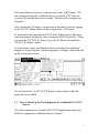
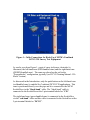
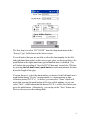
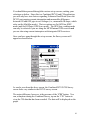
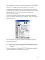
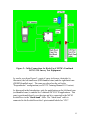
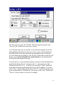
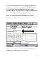
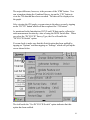
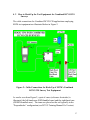
MAN250
DCVG/CIS Switch Box Controller
(Catalog # 12555)
Manual
Revised August 16, 2011
M. C. Miller Co., Inc.
11640 U.S. Highway 1, Sebastian, FL 32958
Telephone: 772 794 9448; Website: www.mcmiller.com
CONTENTS
Page
SECTION 1: INTRODUCTION ……………………………………..
3
SECTION 2: HOW TO USE THE SWITCH BOX WITH THE
DA METER
2. 1
2. 2
How to Set Up Combined Surveys …………………………….
How to Hook-Up the Test Equipment for Combined
DCVG/CIS Surveys ………………………………………...
4
6
SECTION 3: HOW TO USE THE SWITCH BOX WITH THE
G1 DATA-LOGGER
3. 1
3. 2
How to Set Up Combined Surveys ……………………………… 8
How to Hook-Up the Test Equipment for Combined
DCVG/CIS Surveys ………………………………………… 11
SECTION 4: HOW TO USE THE SWITCH BOX WITH THE
Gx DATA-LOGGER
4. 1
4. 2
How to Set Up Combined Surveys ……………………………… 13
How to Hook-Up the Test Equipment for Combined
DCVG/CIS Surveys ………………………………………… 17
2
SECTION 1
INTRODUCTION
The MCM Switch Box makes it possible to collect both DCVG survey data
and CIS data from a section of pipeline on a single pass in conjunction with
the DA Meter, the G1 Data-logger, or, the Gx data-logger.
In the combined survey mode, at each measurement location, the DCVG
data are first recorded and then the Switch Box performs a switching
operation that allows the CIS pipe-to-soil voltages to be recorded. When the
CIS data have been recorded, the data-logger “beeps”, which is the signal
that you can move the reference electrodes to the next measurement
location. The data recording process is initiated using the push-button
switch on the left-hand (red-handled) data-probe. Note: Several cycles
worth of data need to be processed by the data-logger software in order to
record DCVG data and CIS data at each measurement location: First, a
stable DCVG voltage needs to be established following data-probe planting
at a new location, which may require processing of several cycles of data
since the data-probes will both have been off the ground prior to re-planting
the probes. Second, representative On and Off potentials need to be
established following the triggering event which may require processing
several cycles of data since the CIS data will only be available to the
voltmeter following the triggering event (i.e. following the switch from a
cell-to-cell configuration to a pipe-to-cell configuration).
A major difference between Combined DCVG/CIS applications and
conventional DCVG and CIS applications is that, in the Combined
DCVG/CIS case, only the push-button trigger on the left-hand cane (redhandled cane) is enabled (the push-button on the right-hand cane (greenhandled cane) is disabled). Consequently, the left-hand (red-handled) cane’s
push-button switch is used to trigger the (DCVG and CIS) data recording
process. And, since only one data-probe switch is enabled, survey flags, if
used, will have to be designated by tapping on the “Flag” button on the
Survey screen.
3
Prior to performing Combined DCVG/CIS applications, it is highly
recommended that you first use the data-logger to perform individual DCVG
and CIS surveys, in order to become familiar with the test apparatus
(including the data-logger) and the measurement procedures for both survey
types. You are also referred to our DCVG and CIS Training Manuals, which
are companion manuals to your Data-logger User’s Manual, for specific
instructions on how to perform these survey types.
SECTION 2
HOW TO USE THE SWITCH BOX WITH THE
DA METER
2.1 How to Set Up Combined Surveys:
The set up procedures for Combined DCVG/CIS applications, as far as the
DA Meter is concerned, are very similar to those detailed in the DCVG
Training Manual – DA Meter Version.
The first step is to select “DCVG/CIS” from the drop down menu in the
“Survey Type” field shown on the above screen.
4
You will notice that you are not able to select the functionality for the leftand right-hand data-probes in this survey type, since, as discussed above, the
push-button on the right-hand cane (green-handled cane) is disabled. You
will initiate the recording of, first, the DCVG data and, second, the CIS data,
by pressing the left-hand cane’s push-button at each measurement location
down the length of the pipe.
You can, however, select the functionality you desire for the left-hand cane’s
push-button during “Device” measurements, i.e. measurements at datacollection points (D.C.P.’s). As before, you can select “None” which will
mean that pressing the push-button at Devices will do nothing, you can
select “Accept”, which means that the data at D.C.P.’s will be accepted
when you press the push-button and you would then tap on the “save” button
on the “Device” screen to save the data, or you can select “Save”, which
means that the data at D.C.P.’s will be saved when you press the pushbutton. Alternatively, you can tap on the “Save” button on a Device screen
to save the readings data.
You should then proceed through the various set up screens, making your
selections as before. Once you have gone through the set up screens, the
Survey screen will appear as shown below.
As can be seen from the above screen, the Combined DCVG/CIS Survey
screen looks very similar to the DCVG survey screen.
5
The major difference, however, is the presence of the “CIS” button. You
can, at anytime during the Combined Survey, tap on the “CIS” button to
view the CIS data that have been recorded. The data will be displayed on
the graph.
After viewing the CIS graph, you can return to the above screen by tapping
on the “DCVG” button which will have replaced the “CIS button”.
As mentioned in the Introduction, DCVG and CIS data can be collected at
each measurement location by virtue of using the MCM Switch Box. When
you select the “DCVG/CIS” Survey Type, the DA Meter will enable the
“DCVG/CIS Switch” option.
You can check to make sure that this Switch option has been enabled by
tapping on “Survey Options” and then tapping on “Settings” which will pull
up the screen shown below.
The tick beside the “Use DCVG/CIS Switch” option indicates that this
option has been enabled.
2. 2 How to Hook-Up the Test Equipment for Combined DCVG/CIS
Surveys
The cable connections for Combined DCVG/CIS applications employing
MCM test equipment are illustrated below in Figure 1.
6
Figure 1: Cable Connections for Hook-Up of MCM’s Combined
DCVG/CIS Survey Test Equipment
As can be seen from Figure 1, a pair of canes (reference electrodes) is
illustrated, the left-hand cane (RED-handled cane) and the right-hand cane
(GREEN-handled cane). The canes are placed on the soil in the
“Perpendicular” configuration, typically (see DCVG Training Manual - DA
Meter Version).
As discussed in the Introduction, only the push-button on the left-hand cane
(red-handled cane) is enabled for Combined DCVG/CIS applications. This
cane is positioned directly over the pipe and it is connected to the MCM
Switch Box via the “black-band” cable. The “black-band” cable is
connected to the Switch Box at the 5-pin terminal labeled as “CIS”.
The right-hand cane (green-handled cane) is connected to the Switch Box
via the “red-band” cable and this cable is connected to the Switch box at the
5-pin terminal labeled as “DCVG”.
7
The cable connecting the DA Meter to the Switch Box is connected to the 5pin terminal labeled, “Meter”, on the Switch Box. Finally, the banana plug
cable connecting the Hip-Pack (Trail Wire) to the Switch Box is connected
to the banana plug terminal labeled, “Structure” on the Switch Box.
GPS receiver units, if employed, would be connected to the data-logger via
the 9-pin serial data connection terminal on the top-side of the DA Meter
(COM 1 Port). With a GPS unit, the location of items such as flags, devices,
geo-features and anomalies can be recorded during the performance of
combined surveys, either manually by tapping on the “Log GPS” button on
the survey screen at each critical location or automatically by preprogramming the data-logger as described in the data-logger User’s Manual.
SECTION 3
HOW TO USE THE SWITCH BOX WITH THE
G1 DATA-LOGGER
3.1
How to Set Up Combined Surveys
The set up procedures for Combined DCVG/CIS applications are very
similar to those detailed for DCVG surveys in the DCVG Training Manual –
G1 Version.
8
The first step is to select “DCVG/CIS” from the drop down menu in the
“Survey Type” field shown on the above screen.
You will notice that you are not able to select the functionality for the leftand right-hand data-probes in this survey type, since, as discussed above, the
push-button on the right-hand cane (green-handled cane) is disabled. You
will initiate the recording of, first, the DCVG data and, second, the CIS data,
by pressing the left-hand cane’s push-button at each measurement location
down the length of the pipe.
You can, however, select the functionality you desire for the left-hand cane’s
push-button during “Device” measurements, i.e. measurements at datacollection points (D.C.P.’s). As before, you can select “None” which will
mean that pressing the push-button at Devices will do nothing, or you can
select “Save”, which means that the data at D.C.P.’s will be saved when you
press the push-button. Alternatively, you can tap on the “Save” button on a
Device screen to save the readings data.
9
You should then proceed through the various set up screens, making your
selections as before. Since this is a Combined DCVG and CIS application,
you will only have two choices regarding Voltmeter Read Mode (since the
DCVG part requires current-interruption and measurable differences
between ON and OFF pipe-to-soil voltages (i.e., measurable IR drops, which
rules out the Min/Max mode). The two options are On/Off Pairs (DSP
mode) and On/Off Pairs (GPS Sync. mode). The GPS Sync. reading mode
can only be selected if you are using the MCM Internal GPS receiver and
you are also using current-interrupters with integrated GPS receivers.
Once you have gone through the set up screens, the Survey screen will
appear as shown below.
As can be seen from the above screen, the Combined DCVG/CIS Survey
screen looks very similar to the DCVG survey screen.
The major difference, however, is the presence of the “CIS” button. You
can, at anytime during the Combined Survey, tap on the “CIS” button to
view the CIS data that has been recorded. The data will be displayed on the
graph.
10
After viewing the CIS graph, you can return to the above screen by tapping
on the “DCVG” button which will have replaced the “CIS button”.
As mentioned in the Introduction, DCVG and CIS data can be collected at
each measurement location by virtue of using the MCM Switch Box. When
you select the “DCVG/CIS” Survey Type, the G1 will enable the
“DCVG/CIS Switch” option.
You can check to make sure that this Switch option has been enabled by
tapping on “Options” and then tapping on “Settings” which will pull up the
screen shown below.
The tick beside the “Use DCVG/CIS Switch” option indicates that this
option has been enabled.
3. 2 How to Hook-Up the Test Equipment for Combined DCVG/CIS
Surveys
The cable connections for Combined DCVG/CIS applications employing
MCM test equipment are illustrated below in Figure 2.
11
Figure 2: Cable Connections for Hook-Up of MCM’s Combined
DCVG/CIS Survey Test Equipment
As can be seen from Figure 2, a pair of canes (reference electrodes) is
illustrated, the left-hand cane (RED-handled cane) and the right-hand cane
(GREEN-handled cane). The canes are placed on the soil in the
“Perpendicular” configuration (see DCVG Training Manual-G1 Version).
As discussed in the Introduction, only the push-button on the left-hand cane
(red-handled cane) is enabled for Combined DCVG/CIS applications. This
cane is positioned directly over the pipe and it is connected to the MCM
Switch Box via the “black-band” cable. The “black-band” cable is
connected to the Switch Box at the 5-pin terminal labeled as “CIS”.
12
The right-hand cane (green-handled cane) is connected to the Switch Box
via the “red-band” cable and this cable is connected to the Switch box at the
5-pin terminal labeled as “DCVG”.
The cable connecting the G1 data-logger to the Switch Box is connected to
the 5-pin terminal labeled, “Meter”, on the Switch Box. Finally, the banana
plug cable connecting the Hip-Pack (Trail Wire) to the Switch Box is
connected to the banana plug terminal labeled, “Structure” on the Switch
Box.
The GPS Antenna illustrated on the top side of the G1 in Figure 2 represents
the antenna employed by the data-logger’s internal GPS receiver. External
GPS receiver units, if employed, would be connected to the data-logger via
one of the two COM Port terminals located on the bottom side of the G1.
(The right-hand-side COM Port (COM 4) is recommended). With either the
internal unit or an external GPS unit, the location of items such as flags,
devices, geo-features and anomalies can be recorded during the performance
of combined surveys, either manually by tapping on the “Log GPS” button
on the survey screen at each critical location or automatically by preprogramming the data-logger (as described in the data-logger User’s
Manual).
SECTION 4
HOW TO USE THE SWITCH BOX WITH THE
Gx DATA-LOGGER
4.1 How to Set Up Combined Surveys
The set up procedures for Combined DCVG/CIS applications are very
similar to those detailed for DCVG surveys in the DCVG Training Manual –
Gx Data-logger Version.
13
The first step is to select “DCVG/CIS” from the drop down menu in the
“Survey Type” field shown on the above screen.
You will notice that you are not able to select the functionality for the leftand right-hand data-probes for this survey type, since, as discussed above,
the push-button on the right-hand cane (green-handled cane) is disabled.
You will initiate the recording of, first, the DCVG data and, second, the CIS
data, by pressing the left-hand cane’s push-button at each measurement
location down the length of the pipe.
You can, however, select the functionality you desire for the left-hand cane’s
push-button during “Device” measurements, i.e. measurements at datacollection points (D.C.P.’s). As before, you can select “None” which will
mean that pressing the push-button at Devices will do nothing, or you can
select “Save”, which means that the data at D.C.P.’s will be saved when you
press the push-button. Alternatively, you can tap on the “Save” button on a
“Device” screen in order to save device readings.
14
You should then proceed through the various set up screens, making your
selections as before. Since this is a Combined DCVG and CIS application,
you will only have two choices regarding Voltmeter Read Mode (since the
DCVG part requires current-interruption and measurable differences
between ON and OFF pipe-to-soil voltages (i.e., measurable IR drops, which
rules out the Min/Max mode). The two options are On/Off Pairs (DSP
mode) and On/Off Pairs (GPS Sync. mode). The GPS Sync. reading mode
can only be selected if you are using the MCM Internal GPS receiver and
you are also using current-interrupters with integrated GPS receivers.
Once you have gone through the set up screens, the Survey screen will
appear as shown below.
As can be seen from the above screen, the Combined DCVG/CIS Survey
screen looks very similar to the DCVG survey screen.
15
The major difference, however, is the presence of the “CIS” button. You
can, at anytime during the Combined Survey, tap on the “CIS” button to
view the CIS data that have been recorded. The data will be displayed on
the graph.
After viewing the CIS graph, you can return to the above screen by tapping
on the “DCVG” button which will have replaced the “CIS button”.
As mentioned in the Introduction, DCVG and CIS data can be collected at
each measurement location by virtue of using the MCM Switch Box. When
you select the “DCVG/CIS” Survey Type, the Gx will enable the
“DCVG/CIS Switch” option.
You can check to make sure that this Switch option has been enabled by
tapping on “Options” and then tapping on “Settings” which will pull up the
screen shown below.
The tick beside the “Use DCVG/CIS Switch” option indicates that this
option has been enabled.
16
4. 2 How to Hook-Up the Test Equipment for Combined DCVG/CIS
Surveys
The cable connections for Combined DCVG/CIS applications employing
MCM test equipment are illustrated below in Figure 2.
Figure 2: Cable Connections for Hook-Up of MCM’s Combined
DCVG/CIS Survey Test Equipment
As can be seen from Figure 2, a pair of canes (reference electrodes) is
illustrated, the left-hand cane (RED-handled cane) and the right-hand cane
(GREEN-handled cane). The canes are placed on the soil typically in the
“Perpendicular” configuration (see DCVG Training Manual-Gx Version).
17
As discussed in the Introduction, only the push-button on the left-hand cane
(red-handled cane) is enabled for Combined DCVG/CIS applications. This
cane is positioned directly over the pipe and it is connected to the MCM
Switch Box via the “black-band” cable. The “black-band” cable is
connected to the Switch Box at the 5-pin terminal labeled as “CIS”.
The right-hand cane (green-handled cane) is connected to the Switch Box
via the “red-band” cable and this cable is connected to the Switch box at the
5-pin terminal labeled as “DCVG”.
The cable connecting the Gx data-logger to the Switch Box is connected to
the 5-pin terminal labeled, “Meter”, on the Switch Box. Finally, the banana
plug cable connecting the Hip-Pack (Trail Wire) to the Switch Box is
connected to the banana plug terminal labeled, “Structure” on the Switch
Box.
The GPS Antenna illustrated on the top side of the Gx in Figure 2 represents
the antenna employed by the data-logger’s internal GPS receiver. External
GPS receiver units, if employed, would be connected to the data-logger via
the serial port located on the bottom side of the Gx. With either the internal
unit or an external GPS unit, the location of items such as flags, devices,
geo-features and anomalies can be recorded during the performance of
combined surveys, either manually by tapping on the “Log GPS” button on
the survey screen at each critical location or automatically by preprogramming the data-logger (as described in the data-logger User’s
Manual).
Revised August 16, 2011
18