1
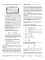
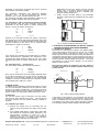
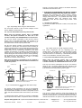
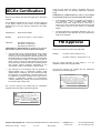
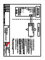
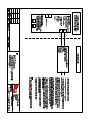
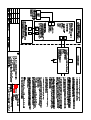
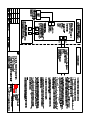
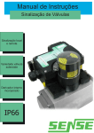
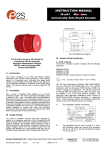
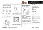
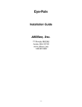
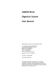
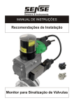
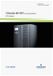
INSTRUCTION MANUAL IS-L101L Intrinsically Safe LED Beacon When used alone, i.e. without a sounder connected, two flash frequencies may be selected. With the Ac.Sw terminals disconnected the beacon will produce two flashes in quick succession once per second. The flash frequency can be doubled by permanently connecting the Ac.Sw terminals together. When used with a sounder, the beacon produces two flashes in quick succession once per second. When the sounder is silenced the flash frequency is automatically doubled. The IS-L101 beacon is CE marked for compliance with the European Explosive Atmospheres Directive 94/9/EC and the European EMC Directive 89/336/EEC 1. INTRODUCTION The IS-L101L is an ATEX and IECEx certified intrinsically safe beacon which will produce a visual warning in a hazardous area. Red, Amber, Green and Blue output models are available. The beacon has been designed and certified to work alone or in conjunction with a European Safety Systems IS-A105N intrinsically safe sounder. The beacon may be powered from the same intrinsically safe circuit as the IS-A105N intrinsically safe sounder, allowing a combined audible and visual alarm to be constructed. The IS-L101L beacon also contains an alarm accept facility which allows an operator to silence the sounder for a predetermined time while leaving the beacon flashing or the sounder can be silenced after a predetermined time period has elapsed. When using the IS-L101L beacon with an IS-A105N sounder, the Special Conditions for Safe Use in the sounder certificate, Sira 04ATEX2301X must also be met. 2. DESCRIPTION Fig 1 shows a simplified block diagram of a IS-L101L beacon. The device will start to flash when power is applied to terminals + and -. Terminals S+ and S- are for the connection of an optional IS-A105N sounder which will operate immediately power is applied to the beacon. The sounder may be silenced for a predetermined time by momentarily connecting the Ac.Sw terminals together. The silence time is set by DIP switches 1 to 4 for time periods between 5 seconds and 2 hours. By setting DIP switch 5 to ON the sounder will silence after a preset time, but sound will not be restored until the power to the beacon has been removed and restored. Setting DIP switch 6 to ON will provide a 1 second reminder beep tone sound while the sounder is silenced. The interval between the 1 second reminder beep is dependent on the timing setting for the silence period, (switches 1 to 4) see page 5. When the beacon is operated alone, without a sounder connected, all of the DIP switches should be set to the OFF position. 3. SUPPLY VOLTAGE The IS-L101L beacon has been designed to operate in a hazardous area via 28V 660mA 1.2W ATEX and IECEx certified Zener Barriers or Galvanic Isolators. The beacon may be tested or used in safe areas without a Zener Barrier or Galvanic Isolator, but at supply voltages above 16V the internal current limit will function and the brightness may be reduced. The beacon should not be continuously operated without a barrier or isolator with a supply voltage greater than 16V. + Current Limit LED's Power Supply 16V S+ Sounder Silence and Timing Circuits S- Connection to Optional IS-A105N Sounder - Accept Switch Fig 1 Simplified block diagram 4. INTRINSIC SAFETY CERTIFICATION 4.1 ATEX certificate The IS-L101L beacon complies with the following standards:EN60079-0:2006 EN60079-11:2007 EN60079-26:2007 IEC60079-0:2007 (used for guidance in respect of marking) II 1G Ex ia IIC T4 Ga (-40ºC <= Ta <= +60ºC) The EC-Type Examination Certificate SIRA 04ATEX2302X has been issued by the Notified Body Sira. This confirms compliance with the European ATEX Directive 94/9/EC for Group II, Category 1G equipment. The beacon carries the Community Mark and subject to local codes of practice, may be installed in any of the EEA member countries. This instruction sheet describes installations which conform to EN60079:Part14:2008 Electrical Installation in Hazardous _______________________________________________________________________________________________________________________________ European Safety Systems Ltd. Impress House, Mansell Road, Acton, London W3 7QH [email protected] Tel: +44 (0)20 8743 8880 www.e2s.com Fax: +44 (0)20 8740 4200 Document No. IS 4601 Issue E 27-11-09 Sheet 1 of 6 Areas. When designing systems for installation outside the UK, the local Code of Practice should be consulted. 1) The certification marking is as follows: IS-L101L Beacon II 1G Ex ia IIC T4 Ga (-40ºC <=Ta<= +60°C) SIRA 04ATEX2302X Ui = 28V Ii = 660mA Pi = 1.2W IECEx SIR 04.0039X Ci = 0 Li = 0 0518 Year / Serial No. 09 / 1R000001 WARNING: TO AVOID A POSSIBLE ELECTROSTATIC CHARGE ONLY CLEAN WITH A DAMP CLOTH e 2S european safety systems ltd. 2) 3) 4) 5) 6) 7) 8) London W3 7QH UK www.e2s.com The equipment may be used in zones 0, 1 and 2 with flammable gases and vapours with apparatus groups IIA, IIB & IIC and with temperature classes T1, T2, T3 and T4. The equipment is only certified for use in ambient o o temperatures in the range -40 C to +60 C and should not be used outside this range. The certificate number has an ‘X’ suffix, which indicates that the certificate contains one of more special conditions for safe use. Those installing or inspecting the equipment should refer to this section of the certificate. The equipment has not been assessed as a safetyrelated device (as referred to by Directive 94/9/EC Annex II, clause 1.5). Installation of this equipment shall be carried out by suitably-trained personnel in accordance with the applicable code of practice. Repair of this equipment shall only be carried out by the manufacturer or in accordance with the applicable code of practice. The certification of this equipment relies on the following materials used in its construction: Enclosure: Lens: ABS Plastic Polycarbonate If the equipment is likely to come into contact with aggressive substances, then it is the responsibility of the user to take suitable precautions that prevent it from being adversely affected, thus ensuring that the type of protection is not compromised. “Aggressive substances” - e.g. acidic liquids or gases that may attack metals, or solvents that may affect polymeric materials. “Suitable precautions” - e.g. regular checks as part of routine inspections or establishing from the material’s data sheet that it is resistant to specific chemicals. SPECIAL CONDITIONS FOR SAFE USE (as stated on the IS-L101L EC Type Examination Certificate SIRA 04ATEX2302X) The enclosure is non-conducting and may generate an ignition-capable level of electrosatic charges under certain extreme conditions. The user should ensure that the equipment is not installed in a location where it may be subjected to external conditions that might cause a buildup of electrostatic charges on non-conducting surfaces, additionally, cleaning of the equipment should be done only with a damp cloth. The equipment has an ingress protection rating of IP 66. However, if it has been supplied without cable entry devices, then the user shall ensure that the devices that are fitted will provide an ingress protection that is appropriate to the environment in which it is installed i.e. IP20 or better. If only one of the two cable entries are used, then the unused entry shall be fitted with a blanking device that ensures ingress protection appropriate to the environment in which it is installed i.e. IP20 or better. SPECIAL CONDITIONS FOR SAFE USE (as stated on the IS-A105N sounder EC Type Examination Certificate SIRA 04ATEX2301X) The equipment shall only be supplied via Terminals + w.r.t. Terminals - from a barrier having a maximum open circuit voltage Uo that is < 28 V and a maximum short circuit current Io that is < 93 mA, where Io is resistively limited. The barrier shall be ATEX certified by a notified body. The total capacitance connected to terminals + wrt – (i.e. the capacitance of the cable plus any other capacitance) shall not exceed 83nF. 4.2 Zones, Gas Groups and T Rating The IS-L101L beacon has been certified Ex ia IIC T4 Ga. When connected to an approved system it may be installed in: Zone 0 explosive gas air mixture continuously present. Zone 1 explosive gas air mixture likely to occur in normal operation. Zone 2 explosive gas air mixture not likely to occur, and if it does, it will only exist for a short time. Be used with gases in groups: Group Group Group A B C propane ethylene hydrogen Having a temperature classification of: T1 T2 T3 T4 450ºC 300ºC 200ºC 135ºC 4.3 Terminals + and - power supply Power is supplied to the beacon via terminals + and - which have maximum input safety parameters of: Ui Ii Pi Ci = 0 = = = 28V 660mA 1.2W Li = 0 IS-L101L beacons may be powered from ATEX certified Zener barriers or galvanic isolators certified by an EC Approved Body with output parameter equal to or less than 28V and 1.2W. Up to three IS-L101L-IS beacons can be connected in parallel and be powered from a common barrier or isolator. Parallel connection of beacons will significantly reduce the _______________________________________________________________________________________________________________________________ European Safety Systems Ltd. Impress House, Mansell Road, Acton, London W3 7QH [email protected] Tel: +44 (0)20 8743 8880 www.e2s.com Fax: +44 (0)20 8740 4200 Document No. IS 4601 Issue E 27-11-09 Sheet 2 of 6 Alternatively, the IS-L101L beacon may be mounted directly onto a IS-A105N sounder enclosure and secured using a joining kit which is available from European Safety Systems Ltd. brightness of each device. Sounders must not be powered from beacons connected in parallel. c. Finally connect the field wiring to the removable terminals, replace the lens and tighten the two captive screws. Ci = 0 28V 660mA 1.2W Li = 0 Ac.Sw However if an IS-A105N sounder was used in conjunction with the beacon a barrier with output parameters 28V 93mA and 660mW where Io is resistively limited must be used (see sounder certificate) so then the S+ and S- terminal safety parameters are equal to or less than: Uo Io Po = = = Ci = 0 28V 93mA 660mW Li = 0 If the beacon and sounder are mounted apart, for intrinsic safety assessment the capacitance and inductance of the interconnecting cable should be added to that of the cable connecting the barrier or isolator to the beacon. See section 4.3. 4.5 Terminals Ac.Sw - accept switch The output safety parameters of these terminals are: Uo Io Po = = = 16.8V 3.61mA 15.2mW They may be connected to any mechanically operated switch in the same hazardous area as the beacon providing the switch has an IP protection suitable for the environmental conditions to which it is subjected and can withstand a 500V rms insulation test to earth for 1 minute. ON = = = PS TS T4 T3 T2 T1 Uo Io Po + - S+ S- 4.4 Terminals S+ and S- connection for optional sounder These terminals have the same maximum output safety parameters as the Zener barrier or isolator powering the beacon, i.e. they are equal to or less than: 1 2 3 4 5 6 The equivalent capacitance and inductance between terminals + and - of the IS-L101Lbeacon and between terminals + and - of the IS-A105N sounder are zero. The maximum permitted cable parameters defined by the barrier or isolator certificate must not be exceeded. Fig 2 Location of field terminals and controls. 6. ELECTRICAL SYSTEM DESIGN FOR INSTALLATION IN HAZARDOUS AREAS USING ZENER BARRIERS 6.1 Stand alone operation If the beacon is controlled by a switch in the positive supply, or the power supply is being turned on and off, only a single channel Zener barrier is required as shown in Fig 3. This circuit may also be used if the beacon is being controlled by a mechanically activated switch on the hazardous area side of the barrier. The power supply voltage should be between 20V and the maximum working voltage of the barrier. The circuit will continue to work at lower voltages, but the beacon brilliance will be reduced. Note when the beacon is operated on its own, without a sounder connected, all of the DIP switches should be set to OFF position. Hazardous Area Safe Area IS-L101L Beacon Ac.Sw 28V 1.2W Positive + - + Barrier On/Off 5. INSTALLATION In addition to the certification requirements shown in section 4.2 the environmental conditions must be within the limits shown on the product specification. The beacon enclosure provides IP66 protection and is suitable for installation in an exterior location if an appropriate sealed cable entry is used. 5.1 Mounting The IS-L101L beacon may be secured to any flat surface using the two 6mm diameter fixing holes. The lens should be aimed towards the area where maximum visibility is required. 5.2 Installation procedure Power Supply 0V Fig 3 Using a single channel barrier. If the beacon control switch is in the negative wire and the power supply 0V is earthed, the circuit shown in Fig 4 may be used. For simplicity the two barriers may be combined into one package. The power supply voltage should be between 21V and the maximum working voltage of the 28V barrier. a. Remove the beacon lens by unscrewing the two captive screws and pull the lens away from the back box. b. Fit a suitable cable gland or conduit entry device that will maintain the enclosure ingress protection in the environmental conditions to which the unit is subjected, into one of the holes in the enclosure. Secure the back box to a vertical surface using the 6mm diameter holes in the two fixing lugs. _______________________________________________________________________________________________________________________________ European Safety Systems Ltd. Impress House, Mansell Road, Acton, London W3 7QH [email protected] Tel: +44 (0)20 8743 8880 www.e2s.com Fax: +44 (0)20 8740 4200 Document No. IS 4601 Issue E 27-11-09 Sheet 3 of 6 Hazardous Area sounder, the power supply voltage to the barrier should be maintained at a minimum of 18V. Safe Area IS-L101L Beacon 28V 1.2W Positive + Ac.Sw + Barrier - Power Supply Diode Return Barrier On/Off 0V Fig 4 Single stage alarm using two channel barrier. 7. ELECTRICAL SYSTEM DESIGN FOR INSTALLATION IN HAZARDOUS AREAS USING GALVANIC ISOLATORS. Although more expensive than Zener barriers, galvanic isolators are easier to install as they do not require a high integrity earth connection. Any certified device with output safety parameters below the maximum input safety parameters of the IS-L101L beacon may be used – See section 4.3. 7.1 Stand alone operation Fig 6 shows the basic circuit that is used for all stand alone applications. The circuit will continue to work at lower voltages, but the beacon brilliance will be reduced. Hazardous Area IS-L101L Beacon 6.2 Use with a IS-A105N intrinsically safe sounder When using the IS-L101L beacon with an IS-A105N sounder, the Special Conditions for Safe Use in the sounder certificate, Sira 04ATEX2301X must also be met. Safe Area Galvanic 28V 1.2W Isolator + Ac.Sw + - + On / Off Power Supply - 0V The very low current consumption of the IS-L101L beacon allows it and a IS-A105N intrinsically safe sounder to be powered from a common Zener barrier as shown in Fig 5. This reduces the sounder output by about 2dB. The IS-L101L beacon contains a circuit that will silence the sounder for a pre-set time, but leave the beacon flashing at twice its normal frequency. The sounder silence time is set by internal DIP switches. An operator may therefore silence the audible alarm but be continuously reminded of the alarm condition by the beacon. If the alarm is not cleared within the silence time, the sounder will be reactivated. If the alarm is cleared during the silence time the beacon will stop flashing, but the beacon and the sounder will both be re-activated if the alarm reoccurs. See table 1 on page 5 of these instructions for full DIP switch settings. Note when the beacon is operated on its own, without a sounder connected, all of the DIP switches should be set to OFF the position. Hazardous Area Safe Area IS-L101L Beacon 28V 93mA (see sounder certificate) Positive Accept Switch + S+ IS-A105N Sounder S- Fig 6 Basic circuit for use with a galvanic isolator. The control arrangement will vary depending upon the isolator chosen. The galvanic isolator must be able to supply an output of 30mA at about 16V. This circuit may also be used if the beacon is controlled by a mechanically activated switch on the hazardous area side of the isolator. 7.2 Use with a IS-A105N intrinsically safe sounder When using the IS-L101L beacon with a IS-A105N sounder, the Special Conditions for Safe Use in the sounder certificate, Sira 04ATEX2301X must also be met. The very low current consumption of the IS-L101L beacon allows it and a IS-A105N intrinsically safe sounder to be powered from a common galvanic isolator as shown in Fig 7. This reduces the sounder output by about 2dBA. + Barrier Hazardous Area Safe Area On/Off Power Supply IS-L101L Beacon Galvanic 28V 93mA (see sounder certificate) Isolator 0V Accept Switch + + S+ NOTE: If sounder silence is not required, cut the link across the Ac.Sw connector. Fig 5 Combined beacon and sounder with alarm accept switch The silence accept push-button may be any mechanically operated switch, providing it has an IP protection suitable for the environmental conditions to which it is subjected, located within the same hazardous area as the beacon, see section 4.5. In order that the beacon continues to produce a reasonable light output level when used in conjunction with an IS-A105N S- - On / Off + Power Supply 0V IS-A105N Sounder NOTE If sounder silence is not required, cut the link across the Ac.Sw connector. Fig 7 Combined beacon and sounder with alarm accept switch The IS-L101L beacon contains a circuit that will silence the sounder for a pre-set time, but leave the beacon flashing at twice its normal frequency. The sounder silence time is set by internal DIP switches. An operator may therefore silence the _______________________________________________________________________________________________________________________________ European Safety Systems Ltd. Impress House, Mansell Road, Acton, London W3 7QH [email protected] Tel: +44 (0)20 8743 8880 www.e2s.com Fax: +44 (0)20 8740 4200 Document No. IS 4601 Issue E 27-11-09 Sheet 4 of 6 audible alarm but be continuously reminded of the alarm condition by the beacon. If the alarm is not cleared within the silence time, the sounder will be reactivated. If the alarm is cleared during the silence time the beacon will stop flashing, but the beacon and the sounder will both be reactivated if the alarm reoccurs. See table 1 on page 5 of these instructions for full DIP switch settings. The silence accept push-button may be any mechanically operated switch, providing it has an IP protection suitable for the environmental conditions to which it is subjected, within the hazardous area, see section 4.5. 9. ACCESSORIES 9.1 Beacon to sounder joining kit Comprises an M20 plastic conduit coupler and gasket enabling the beacon to be mounted onto a IS-A105N sounder. This kit is supplied free of charge when a beacon and sounder are purchased at the same time. 10. MAINTENANCE The beacon should be regularly inspected to ensure that it has not been damaged. Frequency of inspection depends upon environmental conditions, but initially we recommend that this should be done annually. No attempt should be made to repair a faulty IS-L101L beacon. Suspect beacons must be returned to European Safety Systems Ltd. or to your local agent for repair. 11. GUARANTEE Beacons which fail within the guarantee period should be returned to European Safety Systems Ltd. or our local agent. It is helpful if a brief description of the fault symptoms is provided. 12. CUSTOMER COMMENTS European Safety Systems Ltd. are always pleased to receive comments from customers about our products and services. All communications are acknowledged and whenever possible, suggestions are implemented. Switch settings for operation with IS-A105N Sounder Note when the beacon is operated on its own, without a sounder connected, all of the DIP switches should be set to OFF position. SW6 PS OFF ON SW5 OS SW4 T4 OFF SW3 T3 OFF SW2 T2 OFF SW1 T1 OFF Timer Periodic sound interval when silenced, when SW6 is ON for (1 second every) forever 10 secs OFF OFF OFF ON 5 secs 5 secs OFF OFF ON OFF 10 secs 5 secs OFF OFF ON ON 20 secs 5 secs OFF ON OFF OFF 30 secs 5 secs OFF ON OFF ON 45 secs 10 secs OFF ON ON OFF 1 min 10 secs OFF ON ON ON 2 mins 10 secs ON OFF OFF OFF 3 mins 30 secs ON OFF OFF ON 5 mins 30 secs ON OFF ON OFF 10 mins 1 min ON OFF ON ON 20 mins 1 min ON ON OFF OFF 30 mins 1 min ON ON OFF ON 45 mins 5 mins ON ON ON OFF 1 hour 5 mins ON ON ON ON 2 hours 5 mins OFF Hold off mode – Accept Switch silences sounder for selected time. ON One-shot mode — Sounder silences after either selected time, or Accept Switch is pressed, whichever occurs first. The sounder is then only restored after the input power supply is removed and restored. No periodic sound while silenced Sound periodically while silenced _______________________________________________________________________________________________________________________________ European Safety Systems Ltd. Impress House, Mansell Road, Acton, London W3 7QH [email protected] Tel: +44 (0)20 8743 8880 www.e2s.com Fax: +44 (0)20 8740 4200 Document No. IS 4601 Issue E 27-11-09 Sheet 5 of 6 IECEx Certification The IS-L101L Beacon has also been approved to the IECEx scheme. If the IS-L101L beacon is used in conjunction with an ISA105N sounder then the following certification conditions apply:CONDITIONS OF CERTIFICATION (as stated on the IS-A105N Sounder IECEx Certificate of Conformity IECEx SIR 04.0038X) The equipment shall only be supplied via Terminals + w.r.t. Terminals - from a certified barrier having a maximum open circuit voltage Uo that is less than or equal to 28 V and a maximum short circuit current Io that is less than or equal to 93 mA, where Io is resistively limited. The total capacitance connected to terminals + wrt – (i.e. the capacitance of the cable plus any other capacitance) shall not exceed 83nF. The installation requirements for IS-L101L beacons approved to the IECEx scheme are the same as the installation requirements for IS-L101L beacons approved to the ATEX directive. Certificate No. IECEx SIR 04.0039X Marking: Ex ia IIC T4 Ga (Ta = -40ºC to +60ºC) Standards: IEC 60079-0:2004 Edition 4 IEC 60079-11:2006 Edition 5 IEC 60079-26:2006 Edition 2 CONDITIONS OF CERTIFICATION (as stated on the IS-L101L Beacon IECEx Certificate of Conformity IECEx SIR 04.0039X) The equipment has an ingress protection rating of IP66; however, if it has been supplied without a cable entry device, then the user shall ensure that the device that is fitted will provide an ingress protection that is appropriate to the environment in which it is installed i.e. IP20 or better. If only one of the two cable entries are used, then the unused entry shall be fitted with a blanking device that ensures ingress protection appropriate to the environment in which it is installed i.e. IP20 or better. The enclosure is non-conducting and may generate an ignition-capable level of electrosatic charges under certain extreme conditions. The user should ensure that the equipment is not installed in a location where it may be subjected to external conditions that might cause a build-up of electrostatic charges on non-conducting surfaces, additionally, cleaning of the equipment should be done only with a damp cloth. FM Approval The IS-L101L Beacon has also been FM Listed. Marking: IS Class I, Zone 0, AEx ia IIC T4 IS Class I, Division 1, Groups A, B, C, D See the Control Drawings D 4627 Sheets 1 to 4 for installation details and entity parameters. The IS-L101L beacons are marked with the certification requirements for the FM approval. IS-L101L Beacon FM APPROVED IS Class l, Division 1, Groups A, B, C, D IS Class I, Zone 0, AEx ia IIC T4 (-40ºC <=Ta<= +60°C) Control Drawing D 4627 Year / Serial No. 09 / 1R000001 WARNINGS: Substitution of components may impair safety To prevent ignition of flammable or combustible atmospheres, disconnect power before servicing TO AVOID A POSSIBLE ELECTROSTATIC CHARGE ONLY CLEAN WITH A DAMP CLOTH The IS-L101L beacons are marked with the certification requirements for the ATEX and IECEx approvals. e 2S european safety systems ltd. London W3 7QH UK www.e2s.com IS-L101L Beacon II 1G Ex ia IIC T4 Ga (-40ºC <=Ta<= +60°C) SIRA 04ATEX2302X Ui = 28V Ii = 660mA Pi = 1.2W IECEx SIR 04.0039X Ci = 0 Li = 0 0518 Year / Serial No. 09 / 1R000001 WARNING: TO AVOID A POSSIBLE ELECTROSTATIC CHARGE ONLY CLEAN WITH A DAMP CLOTH e 2S european safety systems ltd. London W3 7QH UK www.e2s.com _______________________________________________________________________________________________________________________________ European Safety Systems Ltd. Impress House, Mansell Road, Acton, London W3 7QH [email protected] Tel: +44 (0)20 8743 8880 www.e2s.com Fax: +44 (0)20 8740 4200 Document No. IS 4601 Issue E 27-11-09 Sheet 6 of 6 EC DECLARATION OF CONFORMITY Manufacturer: European Safety Systems Ltd. Impress House, Mansell Road, Acton London, W3 7QH, UK Equipment Type: IS-L101L Directive 94/9/EC: Electrical and Mechanical equipment for use in explosive atmospheres (ATEX) Notified Body for EC type Examination: Sira Certification Service Notified Body No.: 0518 Rake Lane, Eccleston, Chester CH4 9JN, UK EC-type Examination Certificate: SIRA 04ATEX2302X Notified Body for Quality Assurance Notification: Sira Certification Service Notified Body No.: 0518 Rake Lane, Eccleston, Chester CH4 9JN, UK Quality Assurance Notification: SIRA 05 ATEX M342 Provisions fulfilled by the equipment: II 1G Ex ia IIC T4 Ga (-40 °C ≤ Ta ≤ +60 °C) Standards applied: EN 60079-0:2006 IEC 60079-0:2007 EN 60079-11 :2007 EN 60079-26:2007 Directive 2004/108/EC: Electromagnetic Compatibility Directive (EMC) Standards applied: EN 61000-6-1:2007 EN 61000-6-2:2005 EN 61000-6-3:2007 EN 61000-6-4:2007 The standards EN 60079-0: 2006 and EN 60079-11:2007 are no longer harmonized. The requirements of these standards have been checked against the harmonized standards EN 60079-0:2009 and EN 60079-11:2012 and there were no major technical changes affecting the latest technical knowledge for the products listed above. On behalf of European Safety Systems Ltd., I declare that, on the date the equipment accompanied by this declaration is placed on the market, the equipment conforms with all technical and regulatory requirements of the above listed directives. Martin Streetz Quality Assurance Manager Telephone: +44 (0)20 8743 8880 Facsimile: +44 (0)20 8740 4200 E-mail: [email protected] www.e2s.com Date and Place of Issue: London, 04/07/2012 Document No: DC-010-Issue_C European Safety Systems Ltd Company Registration No. 2763350 Registered Office: Impress House Mansell Road, London, UK, W3 7QH, UK