1
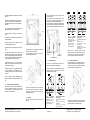
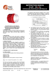
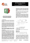
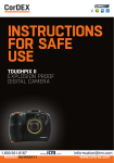
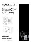
INSTRUCTION MANUAL
BExCP3A-BG Break glass Manual Call Point
For use in Flammable Gas and Dust Atmospheres
The call point switch will now change over it’s
contacts to operate the alarm.
Once testing is complete the unit needs to be
reset, the test key is rotated back anticlockwise by
an angle of 60º back to its original position. The
glass element should now raise up so it is level
again in the viewable window.
BExCP3A-BG
Zone 1
Manual Call Point - Breakglass
For use in Flammable Gas and Zone 2
Combustible Dust Atmospheres.
2)
Marking
All units have a rating label, which carries the
following important information:-
Explosive gas air mixture likely to occur in
normal operation.
Unit Type No.:
BExCP3A-BG
Manual Call
Point
Explosive
gas air mixture
not
likely to occur,
and if it does,
it
will
only
exist
for
a short time.
Input Voltage:
AC voltage 250V Max Current 5.0A Max
DC voltage 50V Max Current 1.0A Max
Code:
Ex e d IIC T6 Gb
Ex t IIIC T60 ºC Db
IP66
–40ºC <= Ta <= +55ºC
1.
Insert test
Key rotate
clockwise
60º
2.
Hold in
position
during
test
3.
Rotate back
anticlockwise
to reset
9)
Replacement of glass element
If the break glass unit has been operated the
broken glass element can be quickly replaced.
Certificate No.:
SIRA 09ATEX3286X
IECEx SIR 09.0121X
To fit the new glass element rotate the top cam
clockwise by an angle of 50º (use a 6mm Allen
key) this will than allow the glass to fit back into the
pocket it sits in, resting on the pivot point and test
cam, release the top cam to rest on the top of the
glass element.
The break glass cover plate is removed by
unscrewing the 4 off M4 cap head screws attaching
it.
Epsilon x:
II 2GD
CE Marking
Notified body No.
0518
Year/Serial No. i.e. 09/1CP3ABG000001
1)
Introduction
The BExCP3A-BG is a break glass manual call
point which is certified to the European and
International Gas and Dust standards. The unit
meets the requirements of the ATEX directive
94/9/EC and IECEx scheme.
The call point can be used in hazardous areas
where potentially flammable gas and dust
atmospheres may be present.
Pivot point
Test Cam
Top Cam (rotate)
Replace the cover plate and tighten the 4 off M4
cap head screws.
Ensure the glass element is free to move under the
cover plate. This can be done by running through
the units test operation. See section 8 of this
instruction manual.
Once cover is removed the broken glass will be
free to be removed, clean out any other fragments
of glass carefully
European Safety Systems Ltd. Impress House, Mansell Road, Acton, London W3 7QH
Document D150-00-001-IS Issue 1 06-06-12
The BExCP3A-BG has no monitoring resistors.
The units are Group II, EPL (equipment protection
level) Gb. The equipment is certified ‘Ex e d IIC T6
Gb’ and as such may be used in Zones 1 and 2
with flammable gases and vapours with gas groups
IIA, IIB & IIC and temperature classes T1, T2, T3,
T4, T5 and T6.
These units are also Group III, EPL Db. The
equipment is certified ‘Ex t IIIC T60ºC Db’ and as
such may be used in Zones 21 and 22 for
combustible dusts groups IIIA, IIIB & IIIC.
Sheet 1 of 2
WARNING - DO NOT OPEN WHEN AN
EXPLOSIVE ATMOSPHERE MAY BE PRESENT
3)
Type Approval Standards
The beacon has an EC Type examination
certificate issued by SIRA and have been approved
to the following standards:IEC 60079-0:2007
EN 60079-1:2004 / IEC 60079-1:2003
EN 60079-7:2007 / IEC 60079-7:2006
IEC 60079-18:2009
EN 61241-1:2004 / IEC 61241-1:2004
The equipment is certified for use in ambient
temperatures in the range -40oC to +55oC and shall
not be used outside this range.
4)
Installation Requirements
Installation of this equipment shall only be carried
out by suitably trained personnel in accordance
with the applicable code of practice e.g.
[email protected] Tel: +44 (0)208 743 8880
www.e2s.com Fax +44 (0)208 740 4200
IEC 60079-14/EN 60079-14 and IEC 61241-14/EN
61241-14.
It is recommended that a cable crimp lug is used
on the earth wires.
The internal earth wire is placed under a earth
clamp which will stop the cable twisting. This is
secured by an M4 screw and spring washer.
The external earth lug should be located between
the two M5 washers provided and securely locked
down with the M5 spring washer and two locknuts.
9) Repair of this equipment shall only be carried
out by the manufacturer or in accordance with the
applicable code of practice e.g. IEC 60079-19/EN
60079-19.
10) The certification of this equipment relies on the
following materials used in its construction:
Enclosure: Aluminium Pressure Die Cast Body
LM6
Unit
in
‘Standby
condition’ unoperated
Terminal +(1) & (3)
Terminal +(4) & (6) switch
contacts closed
Terminals+ (1) &- (2)
Terminals +(4) & -(5)
switch contacts open
Through enclosure mechanism: Plastic Nylon Zytel
Injection Moulded
Sealing of enclosure and mechanism: O-ring
Acrylonitrile-Butadiene Rubber
Potting Compound of resistors where used: Epoxy
Resin
If the equipment is likely to come into contact with
aggressive substances, then it is the responsibility
of the user to take suitable precautions that prevent
it from being adversely affected, thus ensuring that
the type of protection is not compromised.
View of base unit showing fixing centres.
To gain access to the mounting holes in the base
the front cover must be removed.
This is achieved by removing the 4 off M4 cap
head bolts holding on the cover.
Internal Earth
terminal
External
Earth Stud
Unit in ‘Operated condition’
(broken glass)
microswitch contacts changed
over
Terminal +(1) & (3)
Terminal +(4) & (6) switch
contacts open
Terminals +(1) & -(2)
Terminals +(4) & -(5) switch
contacts closed
When wiring to Increased Safety terminal
enclosures, you are only permitted to connect one
wire into each way on the terminal block, unless a
pair of wires are crimped into a suitable ferrule.
Ex e terminal block
7)
“Aggressive substances” - e.g. acidic liquids or
gases that may attack metals, or solvents that may
affect polymeric materials.
Cable connections
There are 3 off cable entries for M20x1.5 Ex e
approved cable glands or stopping plugs
“Suitable precautions” - e.g. regular checks as part
of routine inspections or establishing from the
material’s data sheet that it is resistant to specific
chemicals.
8)
Testing unit operation
The break glass unit can be tested without the
need to break/replace the frangible glass element.
A test key (7mm Allen key) is used to mechanically
drop the glass down activating the switch.
The unit can be wired in a number of different ways
depending whether normally open or normally
closed contacts are required.
Refer to certificates SIRA 09ATEX3286X and
IECEx SIR 09.0121X for special conditions of safe
use.
5)
Call Point Location and Mounting
The location of the call point should enable ease of
access for operation and testing. The unit should
be mounted using the 4 off fixing holes which will
accept up to M4 sized fixings.
Once the screws are removed the cover will hang
down out of the way to gain access to the Ex e
terminal block, the internal earth terminal and
mounting hole recesses.
6)
Earthing
The unit has both internal and external earth
terminals.
European Safety Systems Ltd. Impress House, Mansell Road, Acton, London W3 7QH
Document D150-00-001-IS Issue 1 06-06-12
Unit
in
‘Standby
condition’ unoperated
Terminal +(2,3) & (6)
switch contacts closed
Terminals +(2,3) & -(4,5)
switch contacts open
Sheet 2 of 2
Unit in ‘Operated condition’
(broken glass)
microswitch contacts changed
over
Terminal +(2,3) & (6) switch
contacts open
Terminals +(2,3) & -(4,5)
switch contacts closed
The test key is inserted in the test cam and rotated
clockwise by an angle of 60º the glass element will
visibly drop down in the viewable window.
[email protected] Tel: +44 (0)208 743 8880
www.e2s.com Fax +44 (0)208 740 4200
EC DECLARATION OF CONFORMITY
Manufacturer:
European Safety Systems Ltd.
Impress House, Mansell Road, Acton
London, W3 7QH, UK
Equipment Type:
BExCP3A-BG, BExCP3A-PB, BExCP3A-PT
BExCP3B-BG, BExCP3B-PB, BExCP3B-PT
Directive 94/9/EC: Electrical and Mechanical equipment for use in explosive atmospheres (ATEX)
Notified Body for EC type Examination:
Sira Certification Service
Notified Body No.: 0518
Rake Lane, Eccleston, Chester CH4 9JN, UK
EC-type Examination Certificate:
SIRA 09ATEX3286X
Notified Body for Quality Assurance Notification:
Sira Certification Service
Notified Body No.: 0518
Rake Lane, Eccleston, Chester CH4 9JN, UK
Quality Assurance Notification:
SIRA 05 ATEX M342
Provisions fulfilled by the equipment:
II 2 GD
Ex e d IIC T6 Gb
Ex t IIIC T60 °C Db
(-40 °C ≤ Ta ≤ +55 °C) or
II 2 GD
Ex e d mb IIC T4 Gb
Ex t IIIC T70 °C Db
(-40 °C ≤ Ta ≤ +50 °C)
Standards applied:
IEC 60079-0:2007
EN 60079-1:2004
EN 60079-7:2007
IEC 60079-18:2009
EN 61241-1:2004
Directive 2004/108/EC: Electromagnetic Compatibility Directive (EMC)
Standards applied:
EN 61000-6-1:2007
EN 61000-6-2:2005
EN 61000-6-3:2007
EN 61000-6-4:2007
The standards EN 60079-1:2004, EN 61241-0:2006 and EN 61241-1:2004 are no longer harmonized. The requirements
of these standards have been checked against the harmonized standards EN 60079-1:2007, EN 60079-0:2009 and EN
60079-31:2009 and there were no major technical changes affecting the latest technical knowledge for the products
listed above. Content of IEC 60079-0:2007 is identical to harmonized standard EN 60079-0:2009, content of IEC 6007918:2009 is identical to harmonized standard EN60079-18:2009.
On behalf of European Safety Systems Ltd., I declare that, on the date the equipment accompanied by this declaration is
placed on the market, the equipment conforms with all technical and regulatory requirements of the above listed
directives.
Martin Streetz
Quality Assurance Manager
Telephone: +44 (0)20 8743 8880
Facsimile: +44 (0)20 8740 4200
E-mail: [email protected]
www.e2s.com
Date and Place of Issue: London, 04/07/2012
Document No:
DC-007-Issue_D
European Safety Systems Ltd
Company Registration No. 2763350
Registered Office: Impress House
Mansell Road, London, UK, W3 7QH, UK