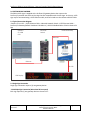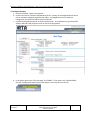
1
Profinet to EDV111 Series LED Signs – Siemens Function Block Software Manual
Electronic Displays, Inc.
EDV111 Series LED Signs
Siemens TIA Portal 11, Step 7 Pro
Function Block Software Manual
Version Control
Version Date
1.0
11/21/2014
Author
d.fox
Change Description
Initial release
EDV111 Series - LED Signs
Firmware Protocol 3.1
Effective 9/21/2014
Version 0.1
Electronic Displays, Inc. EDV111 Series LED Signs
Siemens Step7 Function Block
Software Manual
Page 1 of 27
Profinet to EDV111 Series LED Signs – Siemens Function Block Software Manual
TABLE OF CONTENTS
1.0 INTRODUCTION
1.1 Supported PLC Controllers
1.2 Function Block
1.3 Supported LED Signs
2.0 SYSTEM BLOCK DIAGRAM
2.1 Typical Connection Diagram
2.2 Single Sign Connection
2.3 Multiple Sign Connection
3.0 CONFIGURE RTA 460PSA GATEWAY
3.1 Configure PC Communications
3.2 Configure Gateway
3.3 Configure Siemens PLC
3.4 Import EDI Function Block, Database and PLC Tags
4.0 Use the EDI Function Block
4.1 EDI_Message Function Block Description
4.2 Simple use of the EDI_Message Function Block
4.3 Advanced use of the function block
4.4 Example uses of the function block
4.4.1 Clear display
4.4.2 Colors
4.4.2.1 Red
4.4.2.2 Green
4.4.2.3 Yellow
4.4.3 Flashing
4.4.4 Slide Left
4.4.5 Right Justify
Effective 9/21/2014
Version 0.1
Electronic Displays, Inc. EDV111 Series LED Signs
Siemens Step7 Function Block
Software Manual
Page No.
3
4
5
6
11
16
17
19
20
22
23
24
25
26
27
Page 2 of 27
Profinet to EDV111 Series LED Signs – Siemens Function Block Software Manual
1.0 INTRODUCTION
This manual is provided as a guide for using EVD111 series LED Signs with TIA Portal 11 (Step 7 Pro
v11) software by Siemens. This manual provides instructions for configuring Profinet I/O and
importing function blocks to Step 7 Pro v11 software projects.
1.1 Supported PLC Controllers
Siemens controllers that support Profinet I/O in Step 7 software are supported, such as S7-300, S7400, S7-1200. A sample project is available through the Electronic Displays, Inc. website
www.electronicdisplays.com.
Other Siemens PLC’s are not covered in this document. Typically, these devices may be connected
to a display using a serial port. Please refer to the ASCII protocol manual for examples.
1.2 Function Block
Use the function block described in this manual to easily control an LED sign.
The function block (FB) and data block (DB) may be imported into Step 7 software for use in your
program.
1.3 Supported LED Signs
• EDV111-3280-IND, EDV111-16160-IND, EDV111-16128-IND
• EDV111-1680-IND, EDV11132340-IND, EDV111-16240-IND
• EDV111-24160-IND
Effective 9/21/2014
Version 0.1
Electronic Displays, Inc. EDV111 Series LED Signs
Siemens Step7 Function Block
Software Manual
Page 3 of 27
Profinet to EDV111 Series LED Signs – Siemens Function Block Software Manual
2.0 SYSTEM BLOCK DIAGRAM
The EDV111 LED signs is supplied with a Profinet I/O gateway device that converts the
Profinet I/O protocol into ASCII serial strings that are compatible with the LED signs. In this way, a LED
sign may be connected using a CAT5 Ethernet cable, and not limited to a short distance RS-232 cable.
2.1 Typical Connection Diagram
Siemens S7-nnn PLC > CAT5 Ethernet Cable > Industrial Network Switch > CAT5 Ethernet Cable >
Profinet I/O Gateway (Default IP address 192.168.1.11) > RS-232 Shielded Cable > EDV111 Series LED
Sign
Siemens
S7-1200
CPU
Ethernet
Switch
Profinet Gateway
Ethernet
Ethernet
RS-232
LED Display
2.2 Single Sign Connection
Single sign connection requires (1) one gateway device.
2.3 Multiple Sign Connection (More than 50 Feet apart)
Each sign requires (1) one gateway device as shown in 2.1
Effective 9/21/2014
Version 0.1
Electronic Displays, Inc. EDV111 Series LED Signs
Siemens Step7 Function Block
Software Manual
Page 4 of 27
Profinet to EDV111 Series LED Signs – Siemens Function Block Software Manual
3.0 CONFIGURE RTA 460PSA Profinet Gateway
3.1 Configure PC Communications
On a PC, use the Microsoft Windows “Network and Sharing Center” to configure the “Local Area
Connection” to static IP address 192.168.0.1:
a. In Windows 7, click the START button > Control Panel > Network and Internet > Network and
Sharing Center.
b. Click on the “Local Area Connection” that represents the Ethernet connector that you are
connecting to the gateway.
c. On the “Local Area connection Status” dialog box, click the Properties button.
d. On the “Local Area Connection Properties” dialog box, select “Internet Protocol Version 4
(TCP/IPv4), then click “Properties”.
e. Select the radio box “Use the following IP address:”.
f. In “IP address:”, enter 192.168.0.1
g. In “Subnet mask:”, enter 255.255.255.0
h. Verify DNS servers are empty and click OK.
Effective 9/21/2014
Version 0.1
Electronic Displays, Inc. EDV111 Series LED Signs
Siemens Step7 Function Block
Software Manual
Page 5 of 27
Profinet to EDV111 Series LED Signs – Siemens Function Block Software Manual
3.2 Configure Gateway
a. Connect the power supply to the gateway.
b. Connect an Ethernet crossover cable between the PC. Instead, an unmanaged Ethernet switch
can be used with straight-through Ethernet cables. A managed switch can be used, but
configuration is outside the scope of these instructions.
c. Use Microsoft Windows Explorer or another web browser. In the address bar, type the default
address (192.168.0.100) and press Enter to connect to the gateway.
d. In the upper-right corner of the web page, find “MODE”. If the mode is not “CONFIGURING”,
click the “Configuration Mode” button that appears on the top left, then OK, OK.
Effective 9/21/2014
Version 0.1
Electronic Displays, Inc. EDV111 Series LED Signs
Siemens Step7 Function Block
Software Manual
Page 6 of 27
Profinet to EDV111 Series LED Signs – Siemens Function Block Software Manual
e. On the “Main Page”, review the network settings. To change values, click the “Device
Configuration” “Edit” button.
1. Change “Device Description” to a name that represents how the gateway is being used,
for example, “EDI Display”.
2. Change “IP Address”, “Subnet”, “Default Gateway”, “DNS Gateway” and “Ethernet Link”
to values that are compatible with the associated control system. (Usually, subnet =
255.255.255.0, default and DNS gateway = 0.0.0.0, Ethernet link = Auto-negotiate)
3. Click the “Save Parameters” button to make the change. These settings take effect
when the gateway power is removed and restored.
f.
Click the “Port Configuration” button.
1. Check “Enable Port 0” or “Enable Port 1” but not both.
2. Required settings are
• Mode: RS232
• Stop Bits: 1
• Serial Baud: 9600
• Flow Control: None
• Parity: None
• RTS: High
• Data Bits: 8
• DTR: High
3. Click the “Save Parameters” button to make the change. These settings take effect
when the “Restart Now” button is pressed or the gateway power is removed and
restored.
Effective 9/21/2014
Version 0.1
Electronic Displays, Inc. EDV111 Series LED Signs
Siemens Step7 Function Block
Software Manual
Page 7 of 27
Profinet to EDV111 Series LED Signs – Siemens Function Block Software Manual
g. Click the “PROFINET IO Server” button.
1. Change “Device Label” to “ps01”, without the quotation marks. This name is also used
in the Siemens Step 7 software, and they must match exactly.
2. If the data values are greyed-out, click the “Edit Data Groups” button, OK, OK, OK to
change the following values:
• “Data Size” for all slots except “Slot” 11 should be disabled.
• “Data Format” for all slots except “Slot” 11 should be 16 Bit Int.
• “Slot” 11 “Data Size bytes” is 128, “Data Format” is “Short String”.
3. Click the “Save Parameters” button to make the change. These settings take effect
when the “Restart Now” button is pressed or the gateway power is removed and
restored.
Effective 9/21/2014
Version 0.1
Electronic Displays, Inc. EDV111 Series LED Signs
Siemens Step7 Function Block
Software Manual
Page 8 of 27
Profinet to EDV111 Series LED Signs – Siemens Function Block Software Manual
h. Click the “ASCII” button.
1. Use the “Add ASCII Device” button and the “Delete ASCII Device” buttons so that only
one ASCII device exists named “ASCII Device 1”. Use the << and >> buttons to navigate
through existing ASCII devices.
2. Check the “Enable” checkbox.
3. Change “Port” to “Port 0 (T-strip)” or “Port 1 (DB9)” to match the selected port in “Port
Configuration”
4. Under “Receive Data (ASCII to 460PSA)”, uncheck “Enable”.
5. Under “Transmit Data (460PSA to ASCII)”,
• Check “Enable”
• “Max Message Length” = 128
• “Transmit Timeout” = 0
• Under “Add Delimiters”
⋅ Start = 0, [NUL] 0, [NUL] 0
⋅ End = 0, [NUL] 0, [NUL] 0
6. Click the “Save Parameters” button to make the change. These settings take effect
when the “Restart Now” button is pressed or the gateway power is removed and
restored.
Effective 9/21/2014
Version 0.1
Electronic Displays, Inc. EDV111 Series LED Signs
Siemens Step7 Function Block
Software Manual
Page 9 of 27
Profinet to EDV111 Series LED Signs – Siemens Function Block Software Manual
i.
Remove, then restore power to the gateway. If the IP address was changed, change the IP
address of the PC to a compatible address using the instructions listed earlier in this manual
named “Configure PC Communications”.
j. After the gateway reboots, around ten seconds, enter the IP address of the gateway in the web
browser address bar and press Enter.
k. In the upper-right corner of the web page, find “MODE: RUNNING”. If the mode is not
“RUNNING”, review and verify the PROFINET IO Server settings.
Effective 9/21/2014
Version 0.1
Electronic Displays, Inc. EDV111 Series LED Signs
Siemens Step7 Function Block
Software Manual
Page 10 of 27
Profinet to EDV111 Series LED Signs – Siemens Function Block Software Manual
3.3 Configure Siemens PLC
Note: These instructions are written for Siemens TIA Portal v11, and an S7-1200 CPU.
3.3.1 On the “Start” tab of TIA Portal, open an existing project “in the project view”, or create a new
project with a compatible CPU, then open “in the project view”.
3.3.2 If an RTA Profinet Gateway device has not been configured before,
a. Click the menu item: Options > Install general station description file (GSD).
b. Use the ellipsis (…) and browse to the folder where the GSD files are located.
c. Check the item found and click “Install”.
Effective 9/21/2014
Version 0.1
Electronic Displays, Inc. EDV111 Series LED Signs
Siemens Step7 Function Block
Software Manual
Page 11 of 27
Profinet to EDV111 Series LED Signs – Siemens Function Block Software Manual
3.3.3
Add an RTA Profinet Gateway to the project
a.
b.
c.
d.
e.
f.
In the “Project Tree”, expand the [Project name] > [PLC name] and double-click on
“Device configuration”.
On the [Project name] > “Devices & networks” window, click on the “Network view”
tab.
In the “Hardware catalog” flyout, browse to “Other field devices” > “I/O” > “RTA Inc.” >
“460PSxx” > “port IO Device Conformance Test 1” > “Standard”
Drag “Standard” to an empty space in the “Network view”.
Notice the name “ps01” is assigned, the same as configured on the gateway.
Drag a line from the green square of [PLC name] to the green square of “ps01”.
Effective 9/21/2014
Version 0.1
Electronic Displays, Inc. EDV111 Series LED Signs
Siemens Step7 Function Block
Software Manual
Page 12 of 27
Profinet to EDV111 Series LED Signs – Siemens Function Block Software Manual
3.3.4
Set the IP address of the CPU
a. In the [PLC Name] graphic, right-click on the green square and select “Properties”.
b. On the left side of the “Properties” view, click on “Ethernet addresses”.
c. On the right side of the “Properties” view, enter values that are compatible with the
associated control system. Normal values are
“Interface networked with Subnet” = “PN/IE_1”
Note: This is created by making the connection from the gateway to the CPU.
“IP protocol” = “Set IP address in the project”
“IP address” as needed, for example 192.168.0.10
“Subnet mask” as needed, for example 255.255.255.0
“Use IP router” = not checked
“PROFINET”, “Set PROFINET device name…” = not checked
Effective 9/21/2014
Version 0.1
Electronic Displays, Inc. EDV111 Series LED Signs
Siemens Step7 Function Block
Software Manual
Page 13 of 27
Profinet to EDV111 Series LED Signs – Siemens Function Block Software Manual
3.3.5
Configure the RTA Profinet Gateway device
a. In the “ps01” graphic, right-click on the green square and select “Properties”.
b. On the left side of the “Properties” view, click on “Ethernet addresses”.
c. On the right side of the “Properties” view, enter values that are compatible with the
associated control system. Normal values are
“Interface networked with Subnet” = “PN/IE_1”
Note: This is created by making the connection from the gateway to the CPU.
“IP protocol” = “Use IP protocol”
Other values are default or are not important.
Effective 9/21/2014
Version 0.1
Electronic Displays, Inc. EDV111 Series LED Signs
Siemens Step7 Function Block
Software Manual
Page 14 of 27
Profinet to EDV111 Series LED Signs – Siemens Function Block Software Manual
3.3.6
Choose memory locations for the RTA Profinet Gateway device
a. On the [Project name] > “Devices & networks” window, click on the “Device view” tab.
b. At the top-left of the view, select “ps01” from the “Device Selection” drop-down list.
c. Below the view, expand the “Device Overview” and expand “ps01” > Interface > Rack 0
Slot 11.
d. On the right, expand to find “Hardware Catalog” > “128 bytes O”
e. Drag “128 bytes O” onto “Rack 0 Slot 11”
f. In the “Q address” column, enter a start and end address that does not conflict with
addresses already assigned in the system (Default addresses are 200…327). End address
= start address + 127.
Effective 9/21/2014
Version 0.1
Electronic Displays, Inc. EDV111 Series LED Signs
Siemens Step7 Function Block
Software Manual
Page 15 of 27
Profinet to EDV111 Series LED Signs – Siemens Function Block Software Manual
3.4 Import EDI Function Block, Database and PLC Tags
a.
b.
c.
d.
e.
f.
g.
h.
Start a second instance of TIA Portal software.
On the “Start” tab of TIA Portal, open the reference project named “EDI_S7_1200”.
Click on the “>Project view” to see the project tree.
In the reference project , expand the Project tree to EDI_S7_1200 > PLC_1 > Program blocks.
Right-click on “EDI_Message[FC200]” and click “Copy”.
In your target project, expand the Project tree [Project Name] > PLC_1 > Program Blocks.
Right-click on “Program blocks” and click “Paste”.
Repeat steps e. through g. to copy “EDI_MessageB[DB200]” from the reference project to your
project.
i. In the reference project, expand the project tree to EDI_S7_1200 > PLC_1 > PLC tags.
j. Right-click on “EDI_Display [222]” and click “Copy”.
k. In your target project, expand the Project tree to [Project Name] > PLC_1 > PLC tags.
l. Right-click on “PLC tags” and click “Paste”.
Effective 9/21/2014
Version 0.1
Electronic Displays, Inc. EDV111 Series LED Signs
Siemens Step7 Function Block
Software Manual
Page 16 of 27
Profinet to EDV111 Series LED Signs – Siemens Function Block Software Manual
4.0 Use the EDI Function Block
The EDI function block lets the user send messages to an LED display using the MCS protocol v3.1. The
complete specification for the MCS Protocol is available at www.electronicdisplays.com. Common use
of the protocol is shown in the examples in this section.
4.1 EDI_Message Function Block Description
Effective 9/21/2014
Version 0.1
Electronic Displays, Inc. EDV111 Series LED Signs
Siemens Step7 Function Block
Software Manual
Page 17 of 27
Profinet to EDV111 Series LED Signs – Siemens Function Block Software Manual
“EDI_Message” function block interface
Interface Name
Data Type Description
EN
Bool
Enable EN to transfer the input strings to the LED display.
DB_Number
Int
Set DB_Number to the data block that contains a string used as the
PLC message buffer. This is used by this function block to assemble a
message for the LED display.
Default: The default datablock number is 200 (for DB200). This may be
changed if data block DB200 is needed for something else. The first
member of the datablock must be as follows:
Name: Message
Type: String[128]
Offset: 0
QB
Int
Set QB to the associated I/O output start address that is configured in
the project tree:
Default: The default output address is 200 for (%QB200). This may be
changed if output %QB200 is needed for a different purpose.
Address configuration: YourProjectName > YourPLCName >
Distributed I/O > Profinet IO-System > ps01 >
128 bytes O_1, Q address 200..327
PLC_tag configuration: YourProjectName > YourPLCName >
PLC_tags > EDI_Display[222] > EDI_Display type Char,
Address %QB200
Clear
Bool
Use Clear to manage the PLC message buffer.
Set to TRUE or FALSE to clear or retain the PLC message buffer.
This allows more text to be added with another call to this function.
String1
Use String1 through String4 to add text to the PLC message buffer.
If Clear is True, the buffer is cleared
String2
String1 is added to the buffer
String
String2 is added to the buffer
String3
String3 is added to the buffer
String4
String4 is added to the buffer
Complete
Bool
MessageBuffer
String
ER
ErrorCode
Bool
Bool
Effective 9/21/2014
Version 0.1
Use Complete to send the PLC message buffer to the display
Set to TRUE to send the PLC message buffer
1) The message buffer is copied to the specified %QB output.
2) The Profinet gateway receives the string
3) If the Profinet gateway recognizes a change in the string
(different than previous message), the string is transmitted by RS232
to the display.
Set to FALSE to prevent the message from being sent to the buffer.
For example, if three EDI_Message blocks are used to build a message,
only the last has the Complete bit TRUE.
Set MessageBuffer to the PLC message buffer string
The default string is DB200.Message which is named in the
reference project, "EDI_MessageB".Message
True when the function encounters an error during processing.
0 = No error; 1 = Overflow (Max Length = 128 characters)
Electronic Displays, Inc. EDV111 Series LED Signs
Siemens Step7 Function Block
Software Manual
Page 18 of 27
Profinet to EDV111 Series LED Signs – Siemens Function Block Software Manual
4.2 Simple use of the EDI_Message Function Block
On a new network, add a positive signal edge contact -|P|-. Then drag the EDI_Message [FC200]
block onto the rung. Populate the inputs and outputs like this example:
a.
b.
c.
d.
DBNumber: Datablock DB200
QB: Output byte %QB200
Clear: TRUE to clear the function block buffer and start a new message
String1: ^^^B00^AAA includes the MCS protocol items needed to begin a message.
^^^
Header required for gateway memory alignment
^B
Start of transmission (STX)
00
Address 00
^A
Start command
A
Command: Write to text file
A
Text filename A
e. String1, String2: This the text for display on the LED display.
f. String4: End of transmission (ETX)
g. MessageBuffer: “EDI_MessageB”.Message is the first element of DB200.
h. ER: FALSE if the message size is not ok.
i. ErrorCode: 0 = No error; 1 = Overflow (Max Length = 128 characters)
Note: The message can organized as desired, with unused inputs empty (‘’). For example, this
message could be ‘^^^B00^AAA01234567890120123456789012^C” placed into String1, with the
same results as the example shown above.
Effective 9/21/2014
Version 0.1
Electronic Displays, Inc. EDV111 Series LED Signs
Siemens Step7 Function Block
Software Manual
Page 19 of 27
Profinet to EDV111 Series LED Signs – Siemens Function Block Software Manual
4.3 Advanced use of the function block
The MCS protocol includes many codes used to change colors and display styles. The codes may be
manually entered similar to the ones in example 4.2. Because this might become complicated, the
reference project also comes with a tag table that contains constants for the MCS protocol. These
constants are located in the project tree > [YourProjectName] > [YourPLCName] > PLC Tags >
EDI_Display[222], on the tab named “User constants”. The list is also located in the files EDI_PLC
tags.pdf and EDI_PLC tags.xls, where they are grouped for easier view.
An simple way to use the constants is to copy the name from the .pdf or .xls and paste into the
function block String1-String4 inputs.
Notes: The following example sends this command to the LED display:
^^^B00^AAA^ES^H1^O0RedMessage^O1GreenMessage^C
While this command could be directly entered into a single function block, it might be easier
to use when broken into pieces, with separate function blocks. The contants are not
necessary, but can be used to allow the user to recognize what the program is doing.
Notice the first function block uses the Clear input to start, and the last function block uses
the Complete input to finish. All others have inputs Clear and Complete as FALSE.
How to Choose between using the contants or manual entry of MCS protocol string:
If your project requires a large amount of interaction with the digital display, it might be better to type
the command string. This way, the program size is reduced
If your project only displays simple messages, like fault messages for a machine, it might be better to use
the constants. This way the program is easier to understand and troubleshoot.
Effective 9/21/2014
Version 0.1
Electronic Displays, Inc. EDV111 Series LED Signs
Siemens Step7 Function Block
Software Manual
Page 20 of 27
Profinet to EDV111 Series LED Signs – Siemens Function Block Software Manual
Effective 9/21/2014
Version 0.1
Electronic Displays, Inc. EDV111 Series LED Signs
Siemens Step7 Function Block
Software Manual
Page 21 of 27
Profinet to EDV111 Series LED Signs – Siemens Function Block Software Manual
4.4 Example uses of the function block
4.4.1 Clear display (^^^B00^AAA^C)
Header
Empty
End of Transmission
Effective 9/21/2014
Version 0.1
Electronic Displays, Inc. EDV111 Series LED Signs
Siemens Step7 Function Block
Software Manual
Page 22 of 27
Profinet to EDV111 Series LED Signs – Siemens Function Block Software Manual
4.4.2 Colors
4.4.2.1 Red (^^^B00^AAA^O0Red Text^C)
Header
Color
Red
Text and End of
Transmission
Effective 9/21/2014
Version 0.1
Electronic Displays, Inc. EDV111 Series LED Signs
Siemens Step7 Function Block
Software Manual
Page 23 of 27
Profinet to EDV111 Series LED Signs – Siemens Function Block Software Manual
4.4.2.2 Green(^^^B00^AAA^O1Green Text^C)
Header
Color Green
Text
End of Transmission
4.4.2.2 Yellow(^^^B00^AAA ^O2Yellow Text^C)
Header, Color Yellow,
Text, End of Transmission
Effective 9/21/2014
Version 0.1
Electronic Displays, Inc. EDV111 Series LED Signs
Siemens Step7 Function Block
Software Manual
Page 24 of 27
Profinet to EDV111 Series LED Signs – Siemens Function Block Software Manual
4.4.3 Flashing (^^^B00^AAA ^H1^O0Flashing Red^C)
Header
Character
Attribute
Flashing
Color
Red
Text
End of Transmission
Effective 9/21/2014
Version 0.1
Electronic Displays, Inc. EDV111 Series LED Signs
Siemens Step7 Function Block
Software Manual
Page 25 of 27
Profinet to EDV111 Series LED Signs – Siemens Function Block Software Manual
4.4.4 Slide Left (^^^B00^AAA ^EC^O1SlideLeft^C)
Header
Effect
Color
Green
Slide Left
Text
End of Transmission
Effective 9/21/2014
Version 0.1
Electronic Displays, Inc. EDV111 Series LED Signs
Siemens Step7 Function Block
Software Manual
Page 26 of 27
Profinet to EDV111 Series LED Signs – Siemens Function Block Software Manual
4.4.5 Right Justify (^^^B00^AAA ^PRRight Justify^C)
Header
Position
Right
Text, End of Transmission
Effective 9/21/2014
Version 0.1
Electronic Displays, Inc. EDV111 Series LED Signs
Siemens Step7 Function Block
Software Manual
Page 27 of 27