1
M3T-MR32R V.3.50
Real-time OS for M32R Family
User’s Manual
Rev. 1.00
June 1, 2003
REJ10J0084-0100Z
• Microsoft, MS-DOS, Windows, and Windows NT are registered trademarks of Microsoft Corporation in the U.S. and other
countries.
• IBM and AT are registered trademarks of International Business Machines Corporation.
• Intel and Pentium are registered trademarks of Intel Corporation.
• Adobe, Acrobat, and Acrobat Reader are trademarks of Adobe Systems Incorporated.
• All other brand and product names are trademarks, registered trademarks or service marks of their respective holders.
Keep safety first in your circuit designs!
Renesas Technology Corporation and Renesas Solutions Corporation put the maximum effort into making semiconductor
products better and more reliable, but there is always the possibility that trouble may occur with them. Trouble with semiconductors may lead to personal injury, fire or property damage. Remember to give due consideration to safety when making
your circuit designs, with appropriate measures such as (i) placement of substitutive, auxiliary circuits, (ii) use of nonflammable material or (iii) prevention against any malfunction or mishap.
Notes regarding these materials
These materials are intended as a reference to assist our customers in the selection of the Renesas Technology product best
suited to the customer's application; they do not convey any license under any intellectual property rights, or any other rights,
belonging to Renesas Technology Corporation, Renesas Solutions Corporation or a third party.
Renesas Technology Corporation and Renesas Solutions Corporation assume no responsibility for any damage, or infringement of any third-party's rights, originating in the use of any product data, diagrams, charts, programs, algorithms, or circuit
application examples contained in these materials.
All information contained in these materials, including product data, diagrams, charts, programs and algorithms represents
information on products at the time of publication of these materials, and are subject to change by Renesas Technology Corporation and Renesas Solutions Corporation without notice due to product improvements or other reasons. It is therefore
recommended that customers contact Renesas Technology Corporation, Renesas Solutions Corporation or an authorized
Renesas Technology product distributor for the latest product information before purchasing a product listed herein. The information described here may contain technical inaccuracies or typographical errors. Renesas Technology Corporation and
Renesas Solutions Corporation assume no responsibility for any damage, liability, or other loss rising from these inaccuracies
or errors. Please also pay attention to information published by Renesas Technology Corporation and Renesas Solutions
Corporation by various means, including the Renesas home page (http://www.renesas.com).
When using any or all of the information contained in these materials, including product data, diagrams, charts, programs, and
algorithms, please be sure to evaluate all information as a total system before making a final decision on the applicability of
the information and products. Renesas Technology Corporation and Renesas Solutions Corporation assume no responsibility
for any damage, liability or other loss resulting from the information contained herein.
Renesas Technology semiconductors are not designed or manufactured for use in a device or system that is used under
circumstances in which human life is potentially at stake. Please contact Renesas Technology Corporation, Renesas Solutions Corporation or an authorized Renesas Technology product distributor when considering the use of a product contained
herein for any specific purposes, such as apparatus or systems for transportation, vehicular, medical, aerospace, nuclear, or
undersea repeater use.
The prior written approval of Renesas Technology Corporation and Renesas Solutions Corporation is necessary to reprint or
reproduce in whole or in part these materials.
If these products or technologies are subject to the Japanese export control restrictions, they must be exported under a license from the Japanese government and cannot be imported into a country other than the approved destination. Any diversion or reexport contrary to the export control laws and regulations of Japan and/or the country of destination is prohibited.
Please contact Renesas Technology Corporation or Renesas Solutions Corporation for further details on these materials or
the products contained therein.
For inquiries about the contents of this document or product, fill in the text file the installer generates in the following directory
and email to your local distributor.
¥SUPPORT¥Product-name¥SUPPORT.TXT
Renesas Tools Homepage
http://www.renesas.com/en/tools
Preface
The M3T-MR32R(abbreviated as MR32R ) is a real-time operating system1 1for the M32R microcomputers. The MR32R conforms to the µITRON Specification.2
This manual describes the procedures and precautions to observe when you use the MR32R for programming purposes. For the detailed information on individual system call procedures, refer to the
MR32R Reference Manual.
Requirements for MR32R Use
When creating programs based on the MR32R, it is necessary to purchase the following product of
Mitsubishi Electric or third party products.
•
M32R Family Compiler DCC/M32R(Windriver systems, Inc)
•
M32R Family Cross tool M3T-CC32R(abbreviated as CC32R )
•
M32R Family GNU Cross tool M3T-TW32R(abbreviated as TW32R )
When these related products are used, increased program development efficiency is obtained.
Document List
The following sets of documents are supplied with the MR32R.
•
Release Note
Presents a software overview and describes the corrections to the Users Manual and Reference Manual.
•
Users Manual (PDF file)
Describes the procedures and precautions to observe when using the MR32R for programming purposes.
•
Reference Manual (PDF file)
Describes the MR32R system call procedures and typical usage examples. Before reading
the Users Manual, be sure to read the Release Note.
Please read the release note before reading this manual.
Right of Software Use
The right of software use conforms to the software license agreement. You can use the MR32R for
your product development purposes only, and are not allowed to use it for the other purposes. You
should also note that this manual does not guarantee or permit the exercise of the right of software
use.
1
Hereinafter abbreviated "real-time OS"
The µITRON Specification is originated by Dr.Ken Sakamura and his laboratory members at the Faculty Science of University
of Tokyo. Therefore,Dr.Ken Sakamura holds the copyright on the µITRON Specification. By his consent,the MR32R is produced
in compilance with the µITRON Specification.
2
Contents
i
Contents
Chapter 1
User’s Manual Organization ......................................................................................... 1
Chapter 2
General Information ...................................................................................................... 3
2.1
2.2
2.3
Objective of MR32R Development.......................................................................................... 4
Relationship between TRON Specification and MR32R....................................................... 6
MR32R Features...................................................................................................................... 8
Chapter 3
Introduction to MR32R .................................................................................................. 9
3.1
Concept of Real-time OS ....................................................................................................... 10
3.2
System Call ............................................................................................................................ 17
3.3
Task ........................................................................................................................................ 20
3.4
Handler .................................................................................................................................. 28
3.5
MR32R Kernel Structure ...................................................................................................... 31
3.1.1
3.1.2
Why Real-time OS is Necessary .................................................................................... 10
Operating Principles of Real-time OS........................................................................... 13
3.2.1
3.2.2
System Call Processing.................................................................................................. 18
Task Designation in System Call .................................................................................. 19
3.3.1
3.3.2
3.3.3
Task Status ..................................................................................................................... 20
Task Priority and Ready Queue .................................................................................... 25
Task Control Block(TCB) ............................................................................................... 26
3.4.1
System Calls Exclusive for Handlers............................................................................ 30
3.5.1
3.5.2
3.5.3
3.5.4
3.5.5
3.5.6
3.5.7
3.5.8
3.5.9
3.5.10
3.5.11
Module Structure ........................................................................................................... 31
Module Overview............................................................................................................ 32
Task Management Function .......................................................................................... 34
Synchronization functions attached to task ................................................................. 37
Eventflag......................................................................................................................... 40
Semaphore ...................................................................................................................... 42
Mailbox............................................................................................................................ 44
Messagebuffer................................................................................................................. 46
Rendezvous ..................................................................................................................... 51
Interrupt Management Function .................................................................................. 55
Memorypool Management Function ............................................................................. 57
3.5.12
3.5.13
3.5.14
3.5.15
3.5.16
Time Management Function ......................................................................................... 63
System Management Function...................................................................................... 66
Implementation-Dependent........................................................................................... 67
Implementation-Dependent (Mailbox with Priority) ................................................... 68
System Calls That Can Be Issued from Task and Handler......................................... 69
Chapter 4
Applications Development Procedure Overview......................................................... 73
Fixed-size Memorypool Management Function...................................................................................... 57
Variable-size Memorypool Management Function ................................................................................. 59
4.1
4.2
General Description............................................................................................................... 74
Development Procedure Example ........................................................................................ 76
4.2.1
4.2.2
4.2.3
4.2.4
4.2.5
Chapter 5
Applications Program Coding........................................................................................ 76
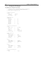
Configuration File Preparation ..................................................................................... 78
Configurator Execution.................................................................................................. 80
System generation.......................................................................................................... 80
Writing ROM .................................................................................................................. 80
Detailed Applications................................................................................................... 81
Contents
ii
5.1
Program Coding Procedure in C Language ......................................................................... 82
5.2
Program Coding Procedure in Assembly Language ............................................................ 88
5.1.1
5.1.2
5.1.3
5.1.4
Task Description Procedure........................................................................................... 82
Writing Interrupt Handler............................................................................................. 85
Writing Cyclic Handler/Alarm Handler........................................................................ 86
Writing Exception (forced exception) handler. ............................................................. 87
5.2.1
5.2.2
5.2.3
5.2.4
Writing Task ................................................................................................................... 88
Writing Interrupt Handler............................................................................................. 90
Writing Cyclic Handler/Alarm Handler........................................................................ 91
Writing Exception (forced exception) handler. ............................................................. 92
Chapter 6
Notes of developing user program............................................................................... 93
6.1
6.2
6.3
6.4
MR32R has four system calls related to delay dispatching................................................ 94
Regarding Initially Activated Task ...................................................................................... 95
A note on using alarm handler ............................................................................................. 95
About dynamic generation and deletion of the objects ....................................................... 96
6.5
6.6
The Use of TRAP Instruction................................................................................................ 97
Regarding Interrupts ............................................................................................................ 98
6.7
The procedure of using OS debug functions ...................................................................... 101
6.8
System Clock Settings......................................................................................................... 103
6.4.1
6.4.2
Structure of Memory in Dynamic Allocation Generation / Deletion ........................... 96
A note on using dynamic generation / deletion............................................................. 97
6.6.1
6.6.2
6.6.3
6.6.4
Controlling Interrupts.................................................................................................... 98
The procedure for running the interrupt handler........................................................ 99
Acception of Interruption at Time of Handler Execution .......................................... 100
Enabling Multiple Interrupts ...................................................................................... 100
6.7.1
6.7.2
The procedure of using OS debug functions ............................................................... 101
Precautions in using OS debug functions ................................................................... 101
6.8.1
Register system clock handler..................................................................................... 103
6.8.2
Automatic system clock settings ................................................................................. 103
Precautions about system clock handler............................................................................................... 103
The structure of system clock settings .................................................................................................. 103
Precautions about automatic timer settings......................................................................................... 103
6.9
Precautions about depending on compiler ......................................................................... 104
6.10
Memory mapping................................................................................................................. 106
6.9.1
6.9.2
6.9.3
When CC32R is used.................................................................................................... 104
When TW32R is used ................................................................................................... 105
When D-CC/M32R is used ........................................................................................... 105
6.10.1
6.10.2
6.10.3
Memory Allocation when Using CC32R...................................................................... 106
Memory Allocation when Using TW32R/D-CC/M32R................................................ 108
Memory Model .............................................................................................................. 110
6.10.4
Chapter 7
7.1
Large model .....................................................................................................................................110
None large model.............................................................................................................................110
Arrangement to Space Exceeding 16MB of Kernel Area ............................................111
Using Configurator .....................................................................................................115
Configuration File Creation Procedure.............................................................................. 116
7.1.1
Configuration File Data Entry Format....................................................................... 116
7.1.2
7.1.3
Configuration File Definition Items............................................................................ 119
Configuration File Example ........................................................................................ 142
7.2.1
Configurator Overview................................................................................................. 145
Operator...................................................................................................................................................117
Direction of computation.........................................................................................................................117
7.2
Configurator Execution Procedures ................................................................................... 145
Contents
7.2.2
7.2.3
7.2.4
7.2.5
7.2.6
iii
Setting Configurator Environment ............................................................................. 147
Configurator Start Procedure...................................................................................... 148
makefile generate Function......................................................................................... 149
Precautions on Executing Configurator...................................................................... 150
Configurator Error Indications and Remedies ........................................................... 151
Error messages .............................................................................................................................. 151
Warning messages ....................................................................................................................... 153
Other messages ............................................................................................................................. 153
Chapter 8
How to Customize ...................................................................................................... 155
8.1
Interruption Control Program ............................................................................................ 156
8.2
How to Customize the MR32R Startup Program .............................................................. 167
8.3
Customizing the Section File .............................................................................................. 185
8.1.1
8.1.2
8.1.3
8.1.4
By the contents interruption processing..................................................................... 156
Interrupt Control Program(for CC32R) ...................................................................... 158
Interrupt Control Program(for TW32R) ..................................................................... 161
Interrupt Control Program(for DCC/M32R)............................................................... 164
8.2.1
8.2.2
8.2.3
8.2.4
8.2.5
Transferring the data to the built-in DRAM from an external ................................. 168
How to Stop Transmission to RAM from ROM .......................................................... 170
Startup Program for C Language(for CC32R)(crt0mr.ms) ........................................ 171
Startup Program for C Language(for TW32R)(crt0mr.s)........................................... 176
Startup Program for C Language(for DCC/M32R)(crt0mr.s) .................................... 181
8.3.1
8.3.2
Using CC32R ................................................................................................................ 185
Using TW32R................................................................................................................ 187
8.3.3
8.3.4
8.3.5
Sample Linker Script ................................................................................................... 188
Using DCC/M32R ......................................................................................................... 193
Sample Linker Script ................................................................................................... 194
8.4.1
8.4.2
Using CC32R ................................................................................................................ 197
Using D-CC/M32R........................................................................................................ 197
Symbols defined in the linker scripts.................................................................................................... 187
8.4
Editing makefile .................................................................................................................. 197
Chapter 9
Application Creation Guide ....................................................................................... 199
9.1
Processing Procedures for System Calls from Handlers................................................... 200
9.2
9.3
Calculating the Amount of RAM Used by the System ...................................................... 203
Stacks ................................................................................................................................... 205
9.1.1
System Calls from a Handler That Caused an Interrupt during Task Execution... 200
9.1.2
System Calls from a Handler That Caused an Interrupt during System Call
Processing.................................................................................................................................... 201
9.1.3
System Calls from a Handler That Caused an Interrupt during Handler Execution
202
9.3.1
Chapter 10
10.1
System Stack and User Stack ..................................................................................... 205
Apendex .................................................................................................................. 207
Sample Program .................................................................................................................. 208
10.1.1
10.1.2
10.1.3
Overview of Sample Program ...................................................................................... 208
Program Source Listing ............................................................................................... 209
Configuration File ........................................................................................................ 211
Index ................................................................................................................................................ 215
iv
Contents
List of Figures
v
List of FIgures
Figure 3.1
Figure 3.2
Figure 3.3
Figure 3.4
Figure 3.5
Figure 3.6
Figure 3.7
Figure 3.8
Figure 3.9
Figure 3.10
Figure 3.11
Figure 3.12
Figure 3.13
Figure 3.14
FIgure 3.15
Figure 3.16
Figure 3.17
Figure 3.18
Figure 3.19
Figure 3.20
Figure 3.21
Figure 3.22
Figure 3.23
Figure 3.24
Figure 3.25
Figure 3.26
Figure 3.27
Figure 3.28
Figure 3.29
Figure 3.30
Figure 3.31
Figure 3.32
Figure 3.33
Figure 3.34
Figure 3.35
Figure 3.36
Figure 3.37
Figure 3.38
Figure 3.39
Figure 3.40
Figure 3.41
Figure 3.42
Figure 3.43
Figure 3.44
Figure 3.45
Figure 3.46
Figure 3.47
Figure 3.48
Figure 4.1
Figure 4.2
Figure 4.3
Relationship between Program Size and Development Period ................................... 10
Microcomputer-based System Example(Audio Equipment)........................................ 11
Example System Configuration with Real-time OS(Audio Equipment) .................... 12
Time-division Task Operation ....................................................................................... 13
Task Execution Interruption and Resumption............................................................. 14
Task Switching ............................................................................................................... 14
Task Register Area ......................................................................................................... 15
Actual Register and Stack Area Management ............................................................. 16
System Call..................................................................................................................... 17
System Call Processing Flowchart ............................................................................ 18
Task Identification...................................................................................................... 19
Task Status ................................................................................................................. 20
MR32R Task Status Transition ................................................................................. 21
Ready Queue (Execution Queue) ............................................................................... 25
Task control block ....................................................................................................... 27
Cyclic Handler/Alarm Handler Activation................................................................ 29
MR32R Structure........................................................................................................ 31
Task Resetting ............................................................................................................ 35
Priority Change........................................................................................................... 35
Ready Queue Management by rot_rdq System Call ................................................ 36
Suspending and Resuming a Task............................................................................. 37
Wake-up Request Storage .......................................................................................... 38
Wake-up Request Cancellation .................................................................................. 39
Task Execution Control by the Eventflag ................................................................. 41
Exclusive Control by Semaphore............................................................................... 42
Semaphore Counter .................................................................................................... 42
Task Execution Control by Semaphore ..................................................................... 43
Mailbox ........................................................................................................................ 44
Meaning of Message ................................................................................................... 44
Message queue Size .................................................................................................... 45
Messagebuffer ............................................................................................................. 46
The example of send message .................................................................................... 47
Send Message.............................................................................................................. 48
Receive Message ......................................................................................................... 49
Rendezvous.................................................................................................................. 51
Multiple rendezvous sessions .................................................................................... 52
Rendezvous forwarding .............................................................................................. 53
Rendezvous reply ........................................................................................................ 54
Interrupt process flow ................................................................................................ 56
Fixed-size Memorypool Management........................................................................ 57
pget_blk processing..................................................................................................... 60
rel_blk processing ....................................................................................................... 61
Release Memory block ................................................................................................ 62
dly_tsk system call...................................................................................................... 63
Timeout Processing..................................................................................................... 64
Cyclic Handler ............................................................................................................ 65
Cyclic Handler; TCY_ON Selected as Activity Status.............................................. 65
Cyclic Handler; TCY_INI_ON Selected as Activity Status ...................................... 65
MR32R System Generation Detail Flowchart.............................................................. 75
Program Example........................................................................................................... 77
Configuration File Example .......................................................................................... 79
vi
List of Figures
Figure 4.4 Configurator Execution.................................................................................................. 80
Figure 4.5 System Generation......................................................................................................... 80
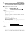
Figure 5.1 Example Infinite Loop Task Described in C Language ............................................... 82
Figure 5.2 Example Task Terminating with ext_tsk() Described in C Language ........................ 83
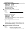
Figure 5.3 Example of Interrupt Handler....................................................................................... 85
Figure 5.4 Example Cyclic Handler Written in C Language......................................................... 86
Figure 5.5 Example Exception Handler Written in C Language .................................................. 87
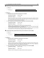
Figure 5.6 Example Infinite Loop Task Described in Assembly Language .................................. 88
Figure 5.7 Example Task Terminating with ext_tsk Described in Assembly Language ............. 88
Figure 5.8 Example of interrupt handler........................................................................................ 90
Figure 5.9 Example Cyclic Handler Written in Assembly Language ........................................... 91
Figure 5.10
Example exception handler Written in Assembly Language ................................... 92
Figure 6.1 Interrupt control in a System Call that can be Issued ................................................ 98
Figure 6.2 The procedure for running the interrupt handler........................................................ 99
Figure 6.3 Allocate OS kernel to the over 16MB area ..................................................................111
Figure 7.1 The operation of the Configurator............................................................................... 146
Figure 8.1 The stack status of interrupt control program ........................................................... 157
Figure 8.2 Startup Program for C Language(for CC32R)............................................................ 175
Figure 8.3 Startup Program for C Language(for TW32R) ........................................................... 180
Figure 8.4 Startup Program for C Language(for DCC/M32R) .................................................... 184
Figure 8.5 The memory image of a sample section file ................................................................ 186
Figure 8.6 The memory image of a sample linker script file ....................................................... 196
Figure 9.1 Processing Procedure for a System Call a Handler that caused an interrupt during
Task Execution............................................................................................................................ 200
Figure 9.2 Processing Procedure for a System Call from a Handler that caused an interrupt
during System Call Processing .................................................................................................. 201
Figure 9.3 Processing Procedure for a system call from a Multiplex interrupt Handler .......... 202
Figure 9.4 System Stack and User Stack ..................................................................................... 205
List of Tables
Table 2.1
MR32R Specifications Overview ..................................................................................... 7
Table 3.1
System Calls Issuable from only Handlers................................................................... 30
Table 3.2
List of the system call can be issued from the task and handler ................................ 69
Table 5.1
C Language Variable Treatment ................................................................................... 84
Table 6.1
Interrupt and Dispatch Status Transition by dis_dsp and loc_cpu ............................ 95
Table 6.2 Dynamic generation / deletion system call list .................................................................. 96
Table 6.3
Interrupt Number Assignment...................................................................................... 97
Table 7.1
Numerical Value Entry Examples............................................................................... 116
Table 7.2
Operators ...................................................................................................................... 116
Table 7.3
Correspondence between microcomputer and template file...................................... 128
Table 8.1
The functions needed in "ipl.ms"................................................................................. 156
Table 9.1
The Size of MR_RAM Section .................................................................................... 203
Table 9.2
The Size of MR_ROM Section.................................................................................... 204
Table 9.3
The Size of INTERRUPT_VECTOR Section .............................................................. 204
Table 10.1 Sample Program Function List ................................................................................... 208
Chapter 1 User’s Manual Organization
Chapter 1 User’s Manual Organization
2
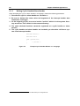
The MR32R User’s Manual consists of nine chapters and thee appendix.
•
Chapter 1 User’s Manual Organization
Outlines the contents of MR32R User’s Manual.
•
Chapter 2 General Information
Outlines the objective of MR32R development and the function and position of the MR32R.
•
Chapter 3 Introduction to MR32R
Explains about the ideas involved in MR32R operations and defines some relevant terms.
•
Chapter 4 Applications Development Procedure Overview
Outlines the applications program development procedure for the MR32R.
•
Chapter 5 Detailed Applications
Details the applications program development procedure for the MR32R.
•
Chapter 7 Using Configurator
Describes the method for writing a configuration file and the method for using the configurator in detail.
•
Chapter 8 How to Customize
This chapter explains how to customize the startup file, the interrupt control program section
file, and makefile so as to make them conform to a user's system.
•
Chapter 9 Application Creation Guide
Presents useful information and precautions concerning applications program development
with MR32R.
•
Chapter 10 Apendex
Describes the MR32R sample applications program which is included in the product in the
form of a source file.
Chapter 2 General Information
Chapter 2 General Information
4
2.1 Objective of MR32R Development
In line with recent rapid technological advances in microcomputers, the functions of microcomputer-based products have become complicated. In addition, the microcomputer program size has increased. Further, as product development competition has been intensified, manufacturers are compelled to develop their microcomputer-based products within a short period of time.
In other words, engineers engaged in microcomputer software development are now required to develop larger-size programs within a shorter period of time. To meet such stringent requirements, it is
necessary to take the following considerations into account.
1. To enhance software recyclability to decrease the volume of software to be developed.
One way to provide for software recyclability is to divide software into a number of functional
modules wherever possible. This may be accomplished by accumulating a number of general-purpose subroutines and other program segments and using them for program development. In this method, however, it is difficult to reuse programs that are dependent on time
or timing. In reality, the greater part of application programs are dependent on time or timing.
Therefore, the above recycling method is applicable to only a limited number of programs.
2. To promote team programming so that a number of engineers are engaged in the development of one software package
There are various problems with team programming. One major problem is that debugging
can be initiated only when all the software program segments created individually by team
members are ready for debugging. It is essential that communication be properly maintained
among the team members.
3. To enhance software production efficiency so as to increase the volume of possible
software development per engineer.
One way to achieve this target would be to educate engineers to raise their level of skill. Another way would be to make use of a structured descriptive assembler, C-compiler, or the
like with a view toward facilitating programming. It is also possible to enhance debugging efficiency by promoting modular software development.
However, the conventional methods are not adequate for the purpose of solving the problems. Under
these circumstances, it is necessary to introduce a new system named real-time OS
To answer the above-mentioned demand, Mitsubishi Electric has developed a real-time operating system, tradenamed MR32R, for use with the M32R 32-bit one-chip microcomputers.
When the MR32R is introduced, the following advantages are offered.
1. Software recycling is facilitated.
When the real-time OS is introduced, timing signals are furnished via the real-time OS so
that programs dependent on timing can be reused. Further, as programs are divided into
modules called tasks, structured programming will be spontaneously provided.
That is, recyclable programs are automatically prepared.
2. Ease of team programming is provided.
When the real-time OS is put to use, programs are divided into functional modules called
tasks. Therefore, engineers can be allocated to individual tasks so that all steps from development to debugging can be conducted independently for each task.
Further, the introduction of the real-time OS makes it easy to start debugging some already
finished tasks even if the entire program is not completed yet. Since engineers can be allocated to individual tasks, work assignment is easy.
3. Software independence is enhanced to provide ease of program debugging.
As the use of the real-time OS makes it possible to divide programs into small independent
modules called tasks, the greater part of program debugging can be initiated simply by
observing the small modules.
2.1 Objective of MR32R Development
5
4. Timer control is made easier.
To perform processing at 10 msec intervals, the microcomputer timer function was formerly
used to periodically initiate an interrupt. However, as the number of usable microcomputer
timers was limited, timer insufficiency was compensated for by, for instance, using one timer
for a number of different processing operations.
When the real-time OS is introduced, however, it is possible to create programs for performing processing at fixed time intervals making use of the real-time OS time management function without paying special attention to the microcomputer timer function. At the same time,
programming can also be done in such a manner as to let the programmer take that numerous timers are provided for the microcomputer.
5. Software maintainability is enhanced.
When the real-time OS is put to use, the developed software consists of small program
modules called tasks. Therefore, increased software maintainability is provided because developed software maintenance can be carried out simply by maintaining small tasks.
6. Increased software reliability is assured.
The introduction of the real-time OS makes it possible to carry out program evaluation and
testing in the unit of a small module called task. This feature facilitates evaluation and testing
and increases software reliability.
7. The microcomputer performance can be optimized to improve the performance of microcomputer-based products.
With the real-time OS, it is possible to decrease the number of unnecessary microcomputer
operations such as I/O waiting. It means that the optimum capabilities can be obtained from
microcomputers, and this will lead to microcomputer-based product performance improvement.
Chapter 2 General Information
6
2.2 Relationship between TRON Specification and MR32R
The TRON Specification is an abbreviation for The Real-time Operating system Nucleus specification.
It denotes the specifications for the nucleus of a real-time operating system. The TRON Project, which
is centered on TRON Specification design, is pushed forward under the leadership of Dr. Ken Sakamura at Faculty of Science, University of Tokyo.
As one item of this TRON Project, the ITRON Specification is promoted. The ITRON Specification is
an abbreviation for the Industrial TRON Specification. It denotes the real-time operating system that is
designed with a view toward establishing industrial real-time operating systems.
The ITRON Specification provides a number of functions to properly meet the application requirements.
In other words, ITRON systems require relatively large memory capacities and enhanced processing
capabilities. The µITRON Specification V.2.0 is the arranged version of the ITRON Specification for the
higher processing speed, and incorporated only a minimum of functions necessary. The µITRON
Specification V.2.0 can be said to be a subset of the ITRON Specification for the following reasons.
1. The system call time-out function is not incorporated.
2. Tasks, semaphores, and other objects can be generated only at the time of system
generation.3 They cannot be generated after system startup.4
3. Only memorypools of a fixed-size can be handled. Memorypools of a variable-size cannot be handled.
4. Neither the system call exception management function nor the CPU exception management function is provided.
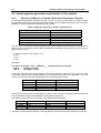
Currently stipulated are µITRON specifications V.3.0. The µITRON specifications V.3.0 provides enhanced connection functions by integrating µITRON specifications V.2.0 and ITRON specifications.
MR32R is a real-time operating system developed for the M32R of 32-bit microprocessors according
to the µITRON specification.45
The µITRON specifications V.3.0 has its system calls classified into level R, level S,level E, and level
C.
MR32R implements all of level R and level S system calls and part of level E system calls among
those stipulated under µITRON specifications V.3.0.
The MR2R specifications are outlined inTable 2.1.
3
4
5
Static object generation.
Dynamic object generation
MR32R V.3.40 conforms to µITRON Specifications V.3.0.
2.2 Relationship between TRON Specification and MR32R
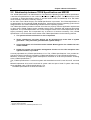
7
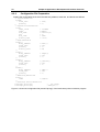
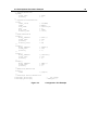
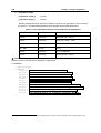
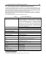
Table 2.1 MR32R Specifications Overview
Item
Target microprocessor
Maximum number of tasks
Task priorities
Maximum number of eventflags
Eventflag width
Maximum number of semaphores
Semaphore type
Maximum number of mailboxes
Message size
Buffer size of Mailbox
Maximum number of Messagebuffer
Maximum number of port for rendezvous
Maximum number of Fixed-size Memorypool
Maximum number of Variable-size Memorypool
Number of system calls
OS nucleus code size
OS nucleus data size
Specifications
M32R Family
32767
255
32766
32 bits
32766
Counter type
32766
32 bits
more tha 4bytes
32765
32765
32766
32766
115
Approx. 4 K to 50 K bytes
81 bytes min.,44 byte increment per task
OS nucleus language
C and Assembly language
* The sum of the number of eventflags, the highest priority, the number of semaphores, the number
of mailbox with priority, (the number of the maximum milbox with priority – the number of mailbox with
priority defined in the configuration file + the number of mailbox with priority defined in the configuration file and specified as TA_TPRI X the highest priority value of tasks ), and number of mailboxes is
not to exceed 32766.
Chapter 2 General Information
8
2.3 MR32R Features
The MR32R offers the following features.
5. Real-time operating system conforming to the µITORN Specification.
The MR32R is designed in compliance with the µITRON Specification which incorporates a
minimum of the ITRON Specification functions so that such functions can be incorporated
into a one-chip microcomputer. As the µ ITRON Specification is a subset of the ITRON
Specification, most of the knowledge obtained from published ITRON textbooks and ITRON
seminars can be used as is.
Further, the application programs developed using the real-time operating systems conforming to the ITRON Specification can be transferred to the MR32R with comparative ease.
6. High-speed processing is achieved.
MR32R enables high-speed processing by taking full advantage of the microcomputer
architecture.
7. Only necessary modules are automatically selected to constantly build up a system of
the minimum size.
The MR32R is supplied in the form of a M32R family microcomputer objective library.
Therefore, the Linkage Editor functions are activated so that only necessary modules are
automatically selected from numerous MR32R functional modules to generate a system.
Thanks to this feature, a system of the minimum size is automatically generated at all times.
8. With the C-compiler NC308, it is possible to develop application programs in C language.
When the C-compiler cc32R or TW32R is used, MR32R application programs can be developed in C language.Also note that an interface library is supplied on software disk to permit
calling up the MR32R functions in C language.
9. An upstream process tool named "Configurator" is provided to simplify development
procedures
A configurator is furnished so that various items including a ROM write form file can be
created by giving simple definitions.
Therefore, there is no particular need to care what libraries must be linked.
Chapter 3 Introduction to MR32R
Chapter 3 Introduction to MR32R
10
3.1 Concept of Real-time OS
This section explains the basic concept of real-time OS.
3.1.1
Why Real-time OS is Necessary
In line with the recent advances in semiconductor technologies, the single-chip microcomputer ROM
capacity has increased. ROM capacity of 32K bytes.
As such large ROM capacity microcomputers are introduced, their program development is not easily
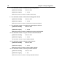
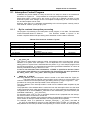
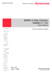
carried out by conventional methods. Figure 3.1 shows the relationship between the program size and
required development time (program development difficulty).
This figure is nothing more than a schematic diagram. However, it indicates that the development period increases exponentially with an increase in program size.
For example, the development of four 8K byte programs is easier than the development of one 32K
byte program.6
Development Period
4
8
16
32
Kbyte
Program Size
Figure 3.1
Relationship between Program Size and Development Period
Under these circumstances, it is necessary to adopt a method by which large-size programs can be
developed within a short period of time. One way to achieve this purpose is to use a large number of
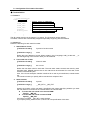
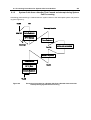
microcomputers having a small ROM capacity. Figure 3.2 presents an example in which a number of
microcomputers are used to build up an audio equipment system.
6
On condition that the ROM program burning step need not be performed.
3.1 Concept of Real-time OS
11
Key input
microcomputer
Remote control
microcomputer
LED illumination
microcomputer
Arbiter
microcomputer
Volume control
microcomputer
Figure 3.2
Monitor
microcomputer
Mechanical
control
microcomputer
Microcomputer-based System Example(Audio Equipment)
Using independent microcomputers for various functions as indicated in the above example offers the
following advantages.
1. Individual programs are small so that program development is easy.
2. It is very easy to use previously developed software.7
3. Completely independent programs are provided for various functions so that program
development can easily be conducted by a number of engineers.
On the other hand, there are the following disadvantages.
1. The number of parts used increases, thereby raising the product cost.
2. Hardware design is complicated.
3. Product physical size is enlarged.
Therefore, if you employ the real-time OS in which a number of programs to be operatedby a number
of microcomputers are placed under software control of one microcomputer, making it appear that the
programs run on separate microcomputers, you can obviate all the above disadvantages while retaining the above-mentioned advantages.
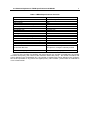
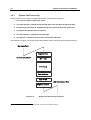
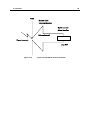
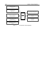
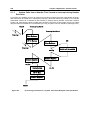
Figure 3.3 shows an example system that will be obtained if the real-time OS is incorporated in the
system indicated in Figure 3.2.
7
In the case presented in Figure 3.2 for instance, the remote control microcomputer can be used for other products without
being modified.
Chapter 3 Introduction to MR32R
12
Key input
Task
Remote control
Task
LED illumination
Task
real-time
OS
Volume control
Task
Figure 3.3
Monitor
Task
Mechanical
control
Task
Example System Configuration with Real-time OS(Audio Equipment)
In other words, the real-time OS is the software that makes a one-microcomputer system look like operating a number of microcomputers.
In the real-time OS, the individual programs, which correspond to a number of microcomputers used in
a conventional system, are called tasks.
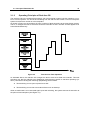
3.1 Concept of Real-time OS
3.1.2
13
Operating Principles of Real-time OS
The real-time OS is the software that makes a one-microcomputer system look like operating a number of microcomputers. You should be wondering how the real-time OS makes a one-microcomputer
system function like a number of microcomputers.
As shown in Figure 3.4 the real-time OS runs a number of tasks according to the time-division system.
That is, it changes the task to execute at fixed time intervals so that a number of tasks appear to be
executed simultaneously.
Key input
Task
Remote control
Task
LED
illumination
Task
Volume control
Task
Monitor
Task
Mechanical
control
Task
Time
Figure 3.4
Time-division Task Operation
As indicated above, the real-time OS changes the task to execute at fixed time intervals. This task
switching may also be referred to as dispatching (technical term specific to real-time operating systems). The factors causing task switching (dispatching) are as follows.
•
Task switching occurs upon request from a task.
•
Task switching occurs due to an external factor such as interrupt.
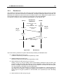
When a certain task is to be executed again upon task switching, the system resumes its execution at
the point of last interruption (See Figure 3.5).
Chapter 3 Introduction to MR32R
14
Program execution
interrupt
Key input
Task
Program execution
resumed
During this interval, it
appears that the key input
microcomputer is haled.
Remote control
Task
Figure 3.5
Task Execution Interruption and Resumption
In the state shown in Figure 3.5, it appears to the programmer that the key input task or its
microcomputer is halted while another task assumes execution control.
Task execution restarts at the point of last interruption as the register contents prevailing at the time of
the last interruption are recovered. In other words, task switching refers to the action performed to
save the currently executed task register contents into the associated task management memory area
and recover the register contents for the task to switch to.
To establish the real-time OS, therefore, it is only necessary to manage the register for each task
and change the register contents upon each task switching so that it looks as if a number of microcomputers exist (See Figure 3.6).
R0
R1
Actual
Register
PC
Real-time OS
Key input
Task
Remote control
Task
R0
R0
R1
R1
PC
PC
Register
Register
Figure 3.6
Task Switching
The example presented in Figure. 3.7 indicates how the individual task registers are managed. In real-
3.1 Concept of Real-time OS
15
ity, it is necessary to provide not only a register but also a stack area for each task.
Memory map
Register
R14
Remote control
Task
PC
SP
R14
Key input
Task
Stack
section
PC
SP
R14
LED illumination
Task
PC
SP
Real-time
OS
SP
Figure 3.7
EIT
Task Register Area
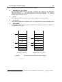
Figure 3.8 shows the register and stack area of one task in detail. In the MR32R, the register of each
task is stored in a stack area as shown in Figure 3.8. This figure shows the state prevailing after register storage.
Chapter 3 Introduction to MR32R
16
R14
SP
R13
Register not stored
R12
R11
R10
R9
R8
R7
R6
R5
R4
Key input task
stack
R3
R2
R1
R0
ACCH
ACCL
BPC
Key input
Task
PSW
SP
Register stored
EIT
Figure 3.8
Actual Register and Stack Area Management
3.2 System Call
17
3.2 System Call
How does the programmer use the real-time OS in a program?
First, it is necessary to call up a real-time OS function from the program in some way or other. Calling
a real-time OS function is referred to as a system call. Task activation and other processing operations
can be initiated by such a system call (See Figure 3.9).
Key input
Task
Remote control
task
Real-time OS
System call
Figure 3.9
Task switching
System Call
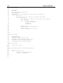
When application programs are to be written in C language, a system call is accomplished by making
a function call, as indicated below.
sta_tsk(ID_main,3);
If application programs are to be written in assembly language, a system call is accomplished by making an assembler macro call, as indicated below.
sta_tsk ID_main,3
Chapter 3 Introduction to MR32R
18
3.2.1
System Call Processing
When a system call is issued, processing takes place in the following sequence.8
1. The current register contents are saved.
2. The stack pointer is changed from the task type to the real-time OS (system) type.
3. Processing is performed in compliance with the request made by the system call.
4. The task to be executed next is selected.
5. The stack pointer is changed to the task type.
6. The register contents are recovered to resume task execution.
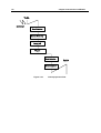
The flowchart in Figure 3.10 shows the process between system call generation and task switching.
Key input Task
Register Save
System call issuance
SP <= OS
Processing
Task Selection
Task => SP
LED illumination Task
Register Restore
Figure 3.10
8
System Call Processing Flowchart
A different sequence is followed if the issued system call does not evoke task switching.
3.2 System Call
3.2.2
19
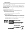
Task Designation in System Call
Within the MR32R real-time OS, each task is identified by ID number.
For example, the system says, "Start the task having the task ID number 1."
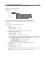
However, if a task number is directly written in a program, the resultant program would be very low in
readability. If, for instance, the following is entered in a program, the programmer is constantly required to know what the No. 2 task is.
sta_tsk(2,1);
Further, if this program is viewed by another person, he/she does not understand at a glance what the
No. 2 task is. To avoid such inconvenience, the MR32R provides means of specifying the task by
name (function or symbol name).
The program named "configurator cfg32r ,"which is supplied with the MR32R, then automatically
converts the task name to the task ID number. This task identification system is schematized in Figure
3.11.
sta_tsk(Task name)
Name
ID number
Starting the task
having the designated
ID number
Configurator
Program
Real-time OS
Figure 3.11
Task Identification
sta_tsk(ID_task,1);
In the above example, the system is instructed to start the task having the function name "task()" or
the symbol name "task:".
It should also be noted that task name-to-ID number conversion is effected at the time of program
generation. Therefore, the processing speed does not decrease due to this conversion feature.
Chapter 3 Introduction to MR32R
20
3.3 Task
This chapter explains how the real-time OS controls the tasks.
3.3.1
Task Status
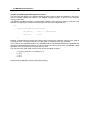
The real-time OS monitors the task status to determine whether or not to execute the tasks.
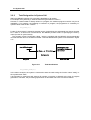
Figure 3.12 shows the relationship between key input task execution control and task status. When
there is a key input, the key input task must be executed. That is, the key input task is placed in the
execution (RUN) state. While the system waits for key input, task execution is not needed. In that
situation, the key input task in the WAIT state.
Key input
Task
Key input
processing
RUN state
Figure 3.12
Waiting for
key input
WAIT state
Key input
processing
RUN state
Task Status
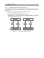
The MR32R controls the following six different states including the RUN and WAIT states.
1. RUN state
2. READY state
3. WAIT state
4. SUSPEND state
5. WAIT-SUSPEND state
6. DORMANT state
7. NON-EXISTENTstate
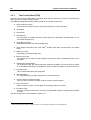
Every task is in one of the above seven different states.Figure 3.13 shows task status transition.
3.3 Task
21
MPU execlusive right acquisition
READY state
RUN state
MPU execlusive right relinquishment
Entering the
WAIT state
WAIT state clear
WAIT state
SUSPEND state clear
request from other task
SUSPEND request
from other task
WAIT-SUSPEND
state
SUSPEND request
from other task
SUSPEND state
clear request
Forced termination
request from other task
Forced
termination
request
from other
task
WAIT state clear
request
SUSPEND
state
DORMANT
state
Task activation
Delete Task
Create Task
NON-EXISTENT
state
Figure 3.13
Exit and Delete itself
MR32R Task Status Transition
1. RUN state
In this state, the task is being executed. Since only one microcomputer is used, it is natural
that only one task is being executed.
The currently executed task changes into a different state when any of the following conditions occurs.
♦ The task has normally terminated itself.9
♦ The task has placed itself in the WAIT state.10
♦ Due to interruption or other event occurrence, the interrupt handler has placed a different
task having a higher priority in the READY state.
♦ The priority assigned to the task has been changed so that the priority of another
READY task is rendered higher.11
♦ Due to interruption or other event occurrence, the priority of the task or a different
READY task has been changed so that the priority of the different task is rendered
9
Upon ext_tsk system call
Upon slp_tsk, tslp_tsk, dly_tsk, wai_flg, twai_flg, wai_sem, twai_sem, rcv_msg or trcv_msg system call.
11
Upon chg_pri system call.
10
Chapter 3 Introduction to MR32R
22
higher.12
When any of the above conditions occurs, rescheduling takes place so that the task having
the highest priority among those in the RUN or READY state is placed in the RUN state, and
the execution of that task starts.
2. READY state
The READY state refers to the situation in which the task that meets the task execution conditions is still waiting for execution because a different task having a higher priority is currently being executed.
When any of the following conditions occurs, the READY task that can be executed second
according to the ready queue13 is placed in the RUN state.
♦
♦
♦
♦
A currently executed task has normally terminated itself.
A currently executed task has placed itself in the WAIT state.
A currently executed task has changed its own priority so that the priority of a different
READY task is rendered higher.14
Due to interruption or other event occurrence, the priority of a currently executed task
has been changed so that the priority of a different READY task is rendered higher.15
3. WAIT state
It exits the RUN state and enters the WAIT state. The WAIT state is usually used as the condition in which the completion of I/O device I/O operation or the processing of some other
task is awaited.
The task goes into the WAIT state in one of the following ways.
♦
The task enters the WAIT state simply when the slp_tsk system call is issued.In this
case, the task does not go into the READY state until its WAIT state is cleared explicitly by some other task.
♦ The task enters and remains in the WAIT state for a specified time period when the
dly_tsk system call is issued. In this case, the task goes into the READY state when
the specified time has elapsed or its WAIT state is cleared explicitly by some other
task.
♦ When the wai_flg, wai_sem, rcv_msg, snd_mbf, rcv_mbf, cal_por, acp_por, get_blf,
get_blk, vrcv_mbx system call is issued, the task enters the WAIT state and waits to
be requested. In this case, the task moves into the READY state when the request
condition is met or its WAIT state is cleared explicitly by some other task.
♦ tslp_tsk, wai_flg, twai_sem, trcv_msg, tsnd_mbf, trcv_mbf, tcal_por, tacp_por, tget_blf,
tget_blk, vtrcv_mbx system call mean slp_tsk, wai_flg, wai_sem, rcv_msg, snd_mbf,
rcv_mbf, cal_por, acp_por, get_blf, get_blk, vrcv_mbx system call with time-out specification. The task is moved to WAIT state by these system calls issue.In this case,the
task is moved to READY state if their conditions are satisfied or the period specified by
tmout elapses without conditions.
When the task enters the WAIT state and waits to be requested upon the issuance of the
wai_flg,wai_sem,rcv_msg,snd_mbf,rcv_mbf,cal_por,acp_por,get_blf,get_blk system call.16
12
Upon ichg_pri system call.
For the information on the ready queue ,see the next chapter
Upon chg_pri system call.
15
Upon ichg_pri system call
16
Upon slp_tsk,dly_tsk,wai_flg,wai_sem ,or rcv_msg system call.
13
14
3.3 Task
23
•
Eventflag Queue
•
Semaphore Queue
•
Mailbox Queue
•
Send Messagebuffer Queue
•
Receive Message Buffer Queue
•
Call Wait Queu
•
Accept Rendezvous Queue
•
Fixed-size memory Allocation Queue
•
Variable-size memory Allocation Queue
•
Mailbox Queue with Priority
4. SUSPEND state
When the sus_tsk system call is issued from a task in the RUN state or the isus_tsk system
call is issued from a handler, the READY task designated by the system call or the currently
executed task enters the SUSPEND state. If a task in the WAIT state is placed in this situation, it goes into the WAIT-SUSPEND state.
The SUSPEND state is the condition in which a READY task or currently executed task is
excluded from scheduling to halt processing due to I/O or other error occurrence. That is,
when the SUSPEND request is made to a READY task, that task is excluded from the execution queue.
Note that no queue is formed for the SUSPEND request. Therefore, the SUSPEND request
can only be made to the tasks in the RUN, READY, or WAIT state. If the SUSPEND request
is made to a task in the SUSPEND state, an error code E_QOVR is returned.
5. WAIT-SUSPEND
When the SUSPEND request is made to a task in the WAIT state, that task goes into the
WAIT-SUSPEND state. When the SUSPEND request is made to a task that is waiting for a
request made by the wai_flg, wai_sem, or rcv_msg system call, that task remains in the request queue and simply goes into the WAIT-SUSPEND state.
When the wait condition for a task in the WAIT-SUSPEND state is cleared, that task goes
into the SUSPEND state.
It is conceivable that the wait condition may be cleared, when any of the following conditions
occurs.
♦
♦
The task wakes up upon wup_tsk,or iwup_tsk system call issuance.
The wait state task by dly_tsk, tslp_tsk system call issuance wakes up upon the period
specified by tmout elapsing.
♦ The request of the task placed in wait state by wai_flg, wai_sem, rcv_msg, snd_mbf,
rcv_mbf, cal_por, acp_por, get_blf, get_blk, vrcv_mbx system call is fullfilled.
♦ The WAIT state is forcibly cleared by the rel_wai or irel_wai system call
When the SUSPEND state clear request 17 is made to a task in the WAIT-SUSPEND
state, that task goes into the WAIT state. Since a task in the SUSPEND state cannot
request to be placed in the WAIT state, status change from SUSPEND to
WAIT-SUSPEND does not possibly occur.
17
rsm_tsk, irsm_tsk systemcall
Chapter 3 Introduction to MR32R
24
6. DORMANT
This state refers to the condition in which a task is registered in the MR32R system but not
activated. This task state prevails when either of the following two conditions occurs.
♦ The task is waiting to be activated.
♦ The task is normally terminated.18 or forcibly terminated.19
7. NON-EXISTENT
The NON-EXISTENT state is a state in which no task is registered in the MR32R system as
it is before a task is generated or as it is after a task has been deleted. A task, if generated,
20
is registered in the MR32R system and is put in the dormant state. This state is brought in
two instances given below.
♦ An instance in which a task in the dormant state is deleted by another task. 21
♦ An instance in which a task under execution terminates and deletes itself. 22
18
19
20
21
22
ext_tsk systemcall
ter_tsk systemcall
cre_tsk systemcall
del_tsk systemcall
exd_tsk systemcall
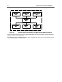
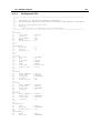
3.3 Task
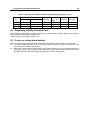
3.3.2
25
Task Priority and Ready Queue
In the real-time OS, several tasks may simultaneously request to be executed.
In such a case, it is necessary to determine which task the system should execute first. To properly
handle this kind of situation, the system organizes the tasks into proper execution priority and starts
execution with a task having the highest priority. To complete task execution quickly, tasks related to
processing operations that need to be performed immediately should be given higher
priorities.
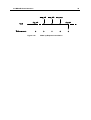
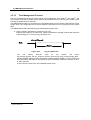
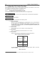
The MR32R permits giving the same priority to several tasks. To provide proper control over the
READY task execution order, the system generates a task execution queue call ed "ready queue."
The ready queue structure is shown in Figure 3.1423. The ready queue is provided and controlled for
each priority level. The first task in the ready queue having the highest priority is placed in the RUN
state. 24
Priority
1
TCB
2
3
TCB
TCB
n
TCB
TCB
Figure 3.14
23
24
TCB
Ready Queue (Execution Queue)
The TCB(task control block is described in the next chapter.)
The task in the RUN state remains in the ready queue.
Chapter 3 Introduction to MR32R
26
3.3.3
Task Control Block(TCB)
The task control block (TCB) refers to the data block that the real-time OS uses for individual task
status, priority, and other control purposes.
The MR32R manages the following task information as the task control block
•
Task connection pointer
Task connection pointer used for ready queue formation or other purposes.
•
Task status
•
Task priority
•
Task attribute
The information of whether the stack area of the task is allocated in internal RAM or in external RAM storage area.
•
Extended information
Extended information of the task storage area.
•
Task register information and other data25 storage stack area pointer(current SP register
value)
•
Wake-up counter
Task wake-up request storage area.
•
Memory block size
The request size of memory block storage area when the task is variable-size memory bloc
wait state.
•
Rendezvous wait bit pattern
For rendezvous calls, the calling-side select condition bit pattern is stored in this area. When
in an acceptance wait state, the acceptance select condition bit pattern is stored in this area.
•
Flag wait mode
This is a wait mode during event flag wait.
•
Wait flag pattern
If in a flag wait state, the flag's wait pattern is stored in this area.
•
Time-out queue connection pointer
Time-out queue connection pointer used for time-out queue formation.
•
Time--out counter
When a task is in a time--out wait state, the remaining wait time is stored.
•
Exception mask
Stores an exception mask value. This area is not allocated unless a forced exception handler
is used 26.
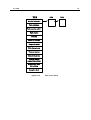
The task control block is schematized in FIgure 3.15.
25
26
Called the task context
Define whether forced exception handler is used or not in the system definition of the configuration file.
3.3 Task
27
TCB
TCB
Extended information
Task attribute
Task connection pointer
Task status
Priority
Wake-up counter
Flag wait mode
Wait flag pattern
Time-out counter
Memory block size
Tioe-out queue
connection pointer
Rendezvous wait
bit pattern
Exception Mask
FIgure 3.15
Task control block
TCB
Chapter 3 Introduction to MR32R
28
3.4 Handler
Difference between Tasks and Handlers
The tasks are program units that the MR32R executes and controls.Each task has its own independent context (program counter, stack pointer, status register, and other registers). Therefore, to transfer
execution from one task to another 27 , it is necessary to effect context switching.
This processing operation takes time.Interrupt processing, which requires high-speed response, can
be carried out by the MR32R without effecting context switching. That is, the interrupted task context
(registers) can be used as is to run a program. This type of program is called the handler. As the handler uses the interrupted task context (registers) as is, it is always necessary to save the interrupted
task context into memory at the beginning of the handler, and put the saved context back into the
original position when returning to the task.
1. Interrupt Handler
A program that starts upon hardware interruption is called the interrupt handler. MR32R activates interrupt handler after interrupt entry process. Interrupt entry process is done in the
MR32R kernel. So, you can only register interrupt handlers in the configuration file.
2. Cyclic Handler
This handler is a program that starts cyclically at preselected time intervals. The cyclic handler activity is to be changed28 determine whether or not to validate a preset cyclic handler.
3. Alarm Handler
This handler starts at preselected times.
The cyclic handler and alarm handler are called up by means of a subroutine call from the system
clock interrupt (timer interrupt) handler (See Figure 3.16). Therefore, the cyclic handler and alarm
handler function as part of the system clock interrupt handler. Note that the cyclic handler and alarm
handler are called up under the conditions whose state is the system clock interrupt priority level.
27
28
This transfer is called dispatching or switching
act_cyc system call
3.4 Handler
29
Task
System clock
interrupt handler
Cyclic handler
Alarm handler
Subroutine call
Timer interrupt
jmp R14
Figure 3.16
Cyclic Handler/Alarm Handler Activation
Chapter 3 Introduction to MR32R
30
3.4.1
System Calls Exclusive for Handlers
In the MR32R, the following system calls can be issued from the handlers only. Note, however, that
the ret_int system call is dedicated to the interrupt handler29 and therefore cannot be issued from the
cyclic handler or alarm handler.
Table 3.1 System Calls Issuable from only Handlers
ichg_pri
irot_rdq
irel_wai
isus_tsk
irsm_tsk
iwup_tsk
iset_flg
isig_sem
isnd_msg
ista_tsk
ret_int
visnd_mbx
29
System call name
Change Task Priority
Rotate Ready Queue
Release Task Wait
Suspend Task
Resume Task
Wakeup Task
Set EventFlag
Signal Semaphore
Send Message to Mailbox
Start Task
Return from Interrupt Handler
Send Message
Function
Changes the task priority.
Rotates the task ready queue.
Forcibly clears the task WAIT state.
Puts a task into the SUSPEND state.
Resumes the suspended task.
Wakes up the waiting task.
Sets an eventflag.
Signal operation for a semaphore.
Sends a message.
Starts the task.
Return from the interrupt handler.
Sends a message.
It isn't necessary to write this system call when specifying the interrupt handler as #pragma INTHANDLER in C language.
3.5 MR32R Kernel Structure
31
3.5 MR32R Kernel Structure
3.5.1
Module Structure
The MR32R kernel consists of the modules shown inFigure 3.17Each of these modules is composed
of functions that exercise individual module features.
The MR32R kernel is supplied in the form of a library, and only necessary features are linked at the
time of system generation. More specifically, only the functions used are chosen from those which
comprise these modules and linked by means of the Linkage Editor. However, the scheduler module,
part of the task management module, and part of the time management module are linked at all times
because they are essential feature functions.
The applications program is a program created by the user.It consists of tasks, interrupt handler, alarm
handler, and cyclic handler.30
User program
Application Program
Task
Management
Mail Box
Semaphore
Time
management
Task-dependent
Synchronization
Eventflag
Memorypool
management
Exception
Management
System
Management
Message
buffer
Rendezvous
Scheduler
mailbox with
priority
Interrupt
Management
M32R Family micro computer
Figure 3.17
30
For details, See 3.5.10
MR32R Structure
MR32R kernel
Hardware
Chapter 3 Introduction to MR32R
32
3.5.2
Module Overview
The MR32R kernel modules are outlined below.
•
•
•
•
•
•
•
•
31
32
Scheduler
Forms a task processing queue based on task priority and controls operation so that the
high-priority task at the beginning in that queue (task with small priority value) is executed.
Task Management Module
Exercises the management of various task states such as the RUN, READY, WAIT, and SUSPEND state
Task Synchronization Module
Accomplishes inter-task synchronization by changing the task status from a different task.
Interrupt Management Module
Makes a return from the interrupt handler
Time Management Module
Sets up the system timer used by the MR32R kernel and starts the user-created alarm handler31 and cyclic handler.32
System Management Module
Reports the MR32R kernel version number or other information.
Sync/Communication Module
This is the function for synchronization and communication among the tasks. The following
three functional modules are offered.
♦ Eventflag
Checks whether the flag controlled within the MR32R is set up and then determines
whether or not to initiate task execution. This results in accomplishing synchronization
between tasks.
♦ Semaphore
Reads the semaphore counter value controlled within the MR32R and then determines whether or not to initiate task execution. This also results in accomplishing
synchronization between tasks.
♦ Mailbox
Provides inter-task data communication by delivering the first data address.
Extended synchronization and communication
This function is provided to synchronize operation between tasks and perform intertask communication. Following two functional modules are available:
♦ Messagebuffer
Performs intertask synchronization and communication simultaneously. Unlike the
mailbox, this function allows variable-size messages to be copied before being transmitted or received.
♦ Rendezvous
Adjusts timing between tasks by keeping messages waiting as necessary.
This handler actuates once only at preselected times.
This handler periodically actuates.
3.5 MR32R Kernel Structure
•
Memorypool Management Function
Provides dynamic allocation or release of a memory area used by a task or a handler.
•
Inplementation Dependent Function
Provides forced exception function and resetting OS resources Function.
•
Inplementation Dependent Function(mailbox with priority)
Provides mailbox with priority Function.
33
Chapter 3 Introduction to MR32R
34
3.5.3
Task Management Function
The task management function is used to perform task operations such as task start/stop and task priority updating. The MR32R kernel offers the following task management function system calls.
•
Creates a task (cre_tsk)
Creates a task having an ID some other task appoints.
•
Delete aTask (del_tsk)
Deletes a task having an ID some other task appoints. The state of the task deleted is
switched from dormant to nonexistent, and releases the stack area.
•
Terminates and deletes a task itself (exd_tsk)
Puts a task itself to normal termination and deletes it. That is, puts a task itself in the nonexistent state, and releases the stack area.
•
Starting the Task (sta_tsk)
Starts the task, changing its status from DORMANT to either READY or RUN.
•
Starting the Task from the handler (ista_tsk)
By activating a task from the handler, the status of the task to be activated is changed from
the DORMANT state to either READY or RUN.
•
Ending Its Own Task (ext_tsk)
Ends its own task and places it in the DORMANT state, so that this task will not be executed
until activated again.
•
Forcibly Terminating Some Other Task (ter_tsk)
Forcibly terminates a different task placed in a state other than DORMANT and places it in
the DORMANT state.
When the forcibly terminated task is activated again, it acts as if it is reset (See Figure 3.18).
3.5 MR32R Kernel Structure
35
TaskA
TaskB
ter_tsk(B)
Terminated
sta_tsk(B)
Reseting TaskB
Figure 3.18
•
Task Resetting
Changing the Task Priority (chg_pri, ichg_pri)
Changes the task priority, and if the task is in the READY or RUN state, updates the ready
queue also (See Figure 3.19).
Priority
1
TCB
TCB
3
TCB
TCB
n
TCB
TCB
2
Figure 3.19
Priority Change
TCB
Chapter 3 Introduction to MR32R
36
•
Rotating the Ready Queue (rot_rdq, irot_rdq)
This system call establishes the TSS (time-sharing system). That is, if the ready queue is rotated at regular intervals, round robin scheduling required for the TSS is accomplished (See
Figure 3.20).
Priority
1
TCB
2
3
TCB
TCB
n
TCB
TCB
TCB
Move the end of the queue
Figure 3.20
Ready Queue Management by rot_rdq System Call
•
Forcibly Clearing the Task WAIT State (rel_wai, irel_wai)
Forcibly clears the task WAIT state. The WAIT state tasks to be cleared by this system call
are those which have entered the WAIT state under the following conditions.
♦ Time-out wait state
♦ Time-out wait state by slp_tsk
♦ Eventflag wait (+ time-out) state
♦ Semaphore wait (+time-out) state
♦ Message wait (+time-out) state
♦ Send message wait (+time-out) state (message buffer)
♦ Recieve message wait (+time-out) state (message buffer)
♦ Call wait (+time-out) state (rendezvous)
♦ Recieve wait (+time-out) state (rendezvous)
♦ Memory block allocation wait (+time-out) state (fixed-size or variable size)
♦ Message wait (+time-out) state(mailbox with priority function)
•
Acquiring Its Own ID (get_tid)
Acquires its own task ID number. When this system call is issued from a handler, 0(zero) is
obtained instead of the ID number.
•
Referencing a task's status (ref_tsk)
Referencing a task's status or priority etc.
3.5 MR32R Kernel Structure
3.5.4
37
Synchronization functions attached to task
The task-dependent synchronization functions attached to task is used to accomplish synchronization
between tasks by placing a task in the WAIT, SUSPEND, or WAIT-SUSPEND state or waking up a
WAIT state task.
The MR32R offers the following task incorporated synchronization system calls.
•
Placing a Task in the SUSPEND State (sus_tsk, isus_tsk)
•
Restarting a Task Placed in SUSPEND State (rsm_tsk, irsm_tsk)
Forcibly suspends or resumes task execution. If a READY task is forced to wait, it enters the
SUSPEND state. If a WAITING state task is forcibly suspended, it enters the
WAIT-SUSPEND state (See Figure 3.21).
READY state
WAIT state
sus_tsk
rsm_tsk
sus_tsk
rsm_tsk
isus_tsk
irsm_tsk
isus_tsk
irsm_tsk
SUSPEND state
Figure 3.21
WAIT-SUSPEND state
Suspending and Resuming a Task
Chapter 3 Introduction to MR32R
38
•
Placing a Task in the WAIT State (slp_tsk,tslp_tsk)
•
Waking up wait state task (wup_tsk, iwup_tsk)
Wakes up a task that has been placed in a WAIT state by the slp_tsk,tslp_tsk system call.
No task can be waked up unless they have been placed in a WAIT state by. 33
If tasks that have been placed in a WAIT state for other conditions than the slp_tsk or tslp_tsk
system call or tasks in other states except one that is in a DORMANT state are waked up by
the wup_tsk or iwup_tsk system call, it results in only wakeup requests being accumulated.
Therefore, if a wakeup request is issued for a task in executing state, for example, that wakeup request is stored in memory temporarily. Then when the task in that executing state is
placed in a wait state by the slp_tsk system call, the accumulated wakeup request becomes
valid, so the task is executed continuously without being placed in a wait state. (See Figure
3.22)
•
Canceling a Task Wake-up Request (can_wup)
Clears the stored wake-up reques.(See Figure 3.23).
wup_tsk
Task
Wake-up count
wup_tsk
slp_tsk
0
Figure 3.22
33
wup_tsk
slp_tsk
0
1
2
Wake-up Request Storage
If the task is WAIT state ,it is not waked-up in any condition as below.
♦
Eventflag waiting
♦
Semaphore Waiting
♦
Message waiting
♦
Timeout waiting
♦
Fixed-size memoryblock waiting
♦
Variable-size memorypool waiting
♦
Port accept waiting
♦
Port call waiting
♦
Rendesvouz waiting
♦
Message buffer receive waiting
♦
Message buffer send waiting
♦
Message waiting for mailbox with priority
1
3.5 MR32R Kernel Structure
39
wup_tsk
Task
Wake-up count
wup_tsk
can_wup
slp_tsk
0
Figure 3.23
slp_tsk
0
1
0
Wake-up Request Cancellation
0
Chapter 3 Introduction to MR32R
40
3.5.5
Eventflag
The eventflag is an internal facility of MR32R that is used to synchronize the execution of multiple
tasks. The eventflag uses a flag wait pattern and a 32-bit pattern to control task execution. A task is
kept waiting until the flag wait conditions set are met.
The MR32R kernel offers the following eventflag system calls.
•
Create eventflag (cre_flg)
Creates an eventflag with the ID specified by a task.
•
Delete eventflag (del_flg)
Deletes an eventflag with the ID specified by a task.
•
Setting the Eventflag (set_flg, iset_flg)
Sets the eventflag so that a task waiting the eventflag is released from the WAIT state.
•
Clearing the Eventflag (clr_flg)
Clearing the Eventflag.
•
Waiting for eventflag (wai_flg, twai_flg)
Waits until the eventflag is set to a certain pattern. There are three modes as listed below in
which the eventflag is waited for.
♦ AND wait
Waits until all specified bits are set.
♦ OR wait
Waits until any one of the specified bits is set.
♦ Clear specification
Clears the flag when the AND wait or OR wait condition is met.
•
Getting eventflag (pol_flg)
Examines whether the eventflag is in a certain pattern. In this system call, tasks are not
placed in a wait state.
• Obtaining the eventflag's status (ref_flg)
References the bit pattern of the relevant eventflag and checks whether a waiting task is present.
Figure 3.24 shows an example of task execution control by the eventflag using the wai_flg and set_flg
system calls.
The eventflag has a feature that it can wake up multiple tasks collectively at a time.
In Figure 3.24, there are six tasks linked one to another, task A to task F. When the flag pattern is set
to 0xF by the set_flg system call, the tasks that meet the wait conditions are removed sequentially
from the top of the queue. In this diagram, the tasks that meet the wait conditions are task A, task C,
task E, and task F. Out of these tasks, task A, task C, and task E are removed from the queue. However, since task E is waiting in clear specification, the flag is cleared when task E is remove from the
queue. Therefore, task F is not removed from the queue.
3.5 MR32R Kernel Structure
TaskA
Flag queue
41
TaskB
TaskC
TaskD
TaskE
TaskF
0xFF
AND
0x0F
AND
0xFF
AND+CLR
0xFF
OR+CLR
0x0F
OR
Flag pattern
0
Wait pattern
Wait mode
0x0F
OR
set_flg
TaskB
TaskD
TaskF
Flag pattern
0x0F
Flag pattern
0x0F
0
Figure 3.24
Task Execution Control by the Eventflag
Chapter 3 Introduction to MR32R
42
3.5.6
Semaphore
The semaphore is a function executed to coordinate the use of devices and other resources to be
shared by several tasks in cases where the tasks simultaneously require the use of them. When, for
instance, four tasks simultaneously try to acquire a total of only three communication lines as shown in
Figure 3.25 , communication line-to-task connections can be made without incurring contention.
Task
Communication
Line
Communication
Line
Task
Communication
Line
Task
Semaphore
Task
Figure 3.25
Exclusive Control by Semaphore
The semaphore has an internal semaphore counter. In accordance with this counter, the semaphore is
acquired or released to prevent competition for use of the same resource.(See Figure 3.26).
Acquired
Task
Returned after use
Figure 3.26
Semaphore Counter
The MR32R kernel offers the following semaphore synchronization system calls.
•
Creates a semaphore (cre_sem)
Creates a semaphore having an ID some other task appoints.
•
Deletes a semaphore (del_sem)
Deletes a semaphore having an ID some other task appoints.
•
Signaling the Semaphore (sig_sem, isig_sem)
Sends a signal to the semaphore. This system call wakes up a task that is waiting for the
semaphores service, or increments the semaphore counter by 1 if no task is waiting for the
3.5 MR32R Kernel Structure
43
semaphores service.
•
Acquiring the Semaphore (wai_sem, twai_sem)
Waits for the semaphores service. If the semaphore counter value is 0 (zero), the semaphore
cannot be acquired. Therefore, the WAIT state prevails.
•
Acquiring the Semaphore (preq_sem)
Acquires the semaphore. If there is no semaphore to acquire, an error code is returned and
the WAIT state does not prevail.
•
Referencing the semaphore's status (ref_sem)
Checks the status of the target semaphore. Checks the count value and existence of the wait
task for the target semaphore.
Figure 3.27 shows example task execution control provided by the wai_sem and sig_sem
systemcalls.
wai_sem
Task
sig_sem
wai_sem
Task
wai_sem
Task
wai_sem
Task
Semaphore
Counter
3
Figure 3.27
2
1
0
x
Task Execution Control by Semaphore
0
Chapter 3 Introduction to MR32R
44
3.5.7
Mailbox
The mailbox is a mechanism that provides data communication between tasks. A typical example is
presented in Figure 3.28. In this example, after task A sends a message in the mailbox, task B can
obtain the message from the mailbox.
Message
Message
TaskA
TaskB
Figure 3.28
Mailbox
The messages that can be placed into this mailbox are 32-bit data
Standard specifications are such that MR32R uses this data as the start address of a message
packet.34 However, this data can be used simply as ordinary data.35
Data
1
2
Message
Packet
Figure 3.29
Meaning of Message
The mailbox is capable of storing messages. Stored messages are retrieved on the FIFO basis.36However, the number of messages that can be stored in the mailbox is limited. The maximum
number of messages that can be stored in the mailbox is referred to as the Message queue size (See
Figure 3.30).
34
35
36
According to the standard stated in ITRON Specification,this data is to be used as the message packet first address.
In this case,Cast to the data of argument of the system call to convert into pointer types.
First in,first out.
3.5 MR32R Kernel Structure
45
Message queue
Message
Size
Message
Message
Message
Figure 3.30
Message queue Size
The MR32R kernel offers the following mailbox system calls.
•
Creates a mailbox (cre_mbx)
Creates a mailbox having an ID some other task appoints.
•
Deletes a mailbox (del_mbx)
Deletes a mailbox having an ID some other task appoints.
•
Transmitting a Message (snd_msg, isnd_msg)
Sends a message or puts a message into the mailbox.
•
Receiving a Message (rcv_msg, trcv_msg)
Receives a message or obtains a message from the mailbox. If the message is not in the
mailbox, the WAIT state prevails until the message is put in the mailbox.
•
Receiving a Message (prcv_msg)
Receives a message. This system call differs from the rcv_msg system call in that the former
returns an error code without incurring the WAIT state if the message is not found in the mailbox.
•
Referencing the mailbox's status (ref_mbx)
Checks whether tasks are present that are waiting for a message to be sent in the relevant
mailbox, and references the first message in the mailbox.
Chapter 3 Introduction to MR32R
46
3.5.8
Messagebuffer
The messagebuffer accomplishes synchronization and communication simultaneously by passing
messages as in the case of the mailbox function. The difference with the mailbox is that it is a copy of
the message content that is transmitted to the receiving task.
Message
Message
Copy
Copy
Messagebuffer
Message
Message
TaskA
TaskB
Figure 3.31
Messagebuffer
As shown in Figure 3.31, the messagebuffer has messages stored in it in the same way as with the
mailbox. The stored messages are retrieved sequentially in order of FIFO.
When sending a message using message buffer functions, M3T-MR32R writes 4-byte size information first and then the message body into the ring buffer. If the previously transmitted message did not
end at a 4-byte boundary, the size info of the message next to be sent is written from the next 4-byte
boundary.
So, a transmit message consumes alignment adjust + 4-byte size info + message body (in bytes) in
the buffer memory. Note that no receive messages contain size information.
3.5 MR32R Kernel Structure
47
[Example]
When message B of 12 bytes wide is sent after message A that was not completed at a 4-byte boundary, the size info of message B is first written from the next 4-byte boundary and then the body of
message B is written successively.
Alignment adjust plus 16 bytes
Message
A
Size
Info
(4bytes)
Message B
(12 bytes)
The beginning of
the buffer area
The end of
the buffer area
means alignment adjust area
Figure 3.32
The example of send message
Chapter 3 Introduction to MR32R
48
There are following messagebuffer system calls that are provided by the MR32R kernel:
•
Create messagebuffer (cre_mbf)
Creates a messagebuffer with the ID specified by a task.
•
Delete messagebuffer (del_mbf)
Deletes a messagebuffer with the ID specified by a task.
•
Send message (snd_mbf, tsnd_mbf)
Transmits a message to the messagebuffer. Namely, a message is copied to the messagebuffer. The messages transferred to the messagebuffer come in varying sizes. Depending on
the free space in the messagebuffer, messages may be or may not be transferred. If the free
space in the messagebuffer is insufficient, the message is kept waiting for transmission.
(See Figure 3.33).
Message
Task A
Message
Message
copy OK
free block
Task B
Message
copy NG
Message
buffer
Send message wait
Figure 3.33
•
37
Send Message
Send message (psnd_mbf)
Transmits a message to the messagebuffer. The difference with snd_mbf and tsnd_mbf is
that when the free space in the messagebuffer is insufficient, this system call returns error
code without keeping the message waiting for transmission37.
An error code E_TMOUT is returned.
3.5 MR32R Kernel Structure
•
49
Receive message (rcv_mbf, trcv_mbf)
Receives a message. A message is retrieved from the messagebuffer. If no message exists
in the messagebuffer, this system call goes to a receive wait state.
When a message is received from the messagebuffer, the free space in the messagebuffer
increases that much. If there is any task kept waiting for transmission and the size of the
message to be transmitted by that task is smaller than the free space in the messagebuffer,
the message is sent to the messagebuffer and the task goes to an execution (RUN) or executable (READY) state.
Task A
1
Message
Recieve
2
Task B
Message
Send
free block
Message
Send
message
wait
Message
Ready
state
Figure 3.34
Message
buffer
Receive Message
When task A is in the execution (RUN) state and task B is in wait state, as in Figure 3.34.
1. Task A receives a message from the messagebuffer.
As a message is received from the messagebuffer, the free space in the messagebuffer increases that much.
2. Task B transmits a message to the messagebuffer.
Task B which has been kept waiting for transmission because the free space in the messagebuffer was insufficient now transmits a message to the messagebuffer as task A has received a message. The status of task B changes from the transmit wait state to an executable
state.
38
•
Receive message (prcv_mbf)
Receives a message. The difference with rcv_mbf and trcv_mbf is that when no message
exists in the messagebuffer, this system call returns error code without going to a receive wait
state 38.
•
Reference messagebuffer status (ref_mbf)
An error code E_TMOUT is returned.
50
Chapter 3 Introduction to MR32R
Checks the target messagebuffer to see if there is any task kept waiting for transmission or
waiting for reception, as well as find the size of the next message to be received.
3.5 MR32R Kernel Structure
3.5.9
51
Rendezvous
The rendezvous function keeps a task (call) and a task (accept) waiting each other through a window
called the "port" and when rendezvous is established, exchanges messages between the tasks. Establishment of rendezvous means that when the AND'ed result of the calling-side bit pattern and receiving-side bit pattern is not 0, rendezvous is assumed to have been established.
This function is useful for server and client implementation on the real-time OS.
Rendezvous
established
Task A
call pattern(000....001)
AND
accept pattern(001...001)
cal_por
tcal_por
pcal_por
Task B
Rendezvous
acceptance
Message transfer
(request)
Rendezvous
call
acp_por
tacp_por
tacp_por
End of
rendezvous
wait
End of
rendezvous
Processing restarted
rpl_rdv
Message transfer (result)
(Reply message)
Port
Figure 3.35
Rendezvous
There are following rendezvous system calls that are provided by the MR32R kernel:
•
Create rendezvous port (cre_por)
Creates a rendezvous port with the ID specified by a task.
•
Delete rendezvous port (del_por)
Deletes a rendezvous port with the ID specified by a task.
•
Make rendezvous call to port (cal_por, tcal_por)
Issues a cal_por or tcal_por system call to check whether rendezvous with the task in the
acceptance wait state at the specified port will be established. When rendezvous is established, a message is transferred to the task in the acceptance wait state and the task goes
from the acceptance wait state to an executable state.
If no task exists that is kept waiting for acceptance at the specified port, or although there is a
task waiting for acceptance, rendezvous establishment condition is not met, the task that issued cal_por or tcal_por is placed in a call wait state, so it is queued up in the call waiting
queue.
•
Make rendezvous call to port (pcal_por)
Chapter 3 Introduction to MR32R
52
Performs the same processing as with the cal_por and tcal_por system calls, except that if no
task exists that is kept waiting for acceptance at the specified port, or although there is a task
waiting for acceptance, rendezvous establishment condition is not met, the issuing task only
returns error code without going to a call wait state.
•
Accept rendezvous call from port (acp_por, tacp_por)
Issues a acp_por or tacp_por system call to check whether rendezvous with the task in the
call wait state at the specified port will be established. When rendezvous is established, the
task kept in the call wait state is removed from the call wait queue and goes to an end of
rendezvous wait state. Note that the task on the rendezvous acceptance side (the task that
issued acp_por) can perform multiple rendezvous sessions simultaneously. Figure 3.35
shows multiple rendezvous sessions at different ports. It is also possible to perform multiple
rendezvous sessions at the same port.
If no task exists that is kept waiting for call at the specified port, or although there is a task
waiting for call, rendezvous establishment condition is not met, the task that issued acp_por
or tacp_por is placed in an acceptance wait state, so it is queued up in the acceptance wait
queue.
TaskA
TaskB
TaskC
Rendezvous
call wait
Rendezvous
call wait
Rendezvous
established
Message transfer
acp_por
End of
rendezvous
Rendezvous
established
Message transfer
acp_por
End of
rendezvous
wait
Port 1
Figure 3.36
Port 2
Multiple rendezvous sessions
•
Accept rendezvous call from port (pacp_por)
Performs the same processing as with the acp_por and tacp_por system calls, except that if
no task exists that is kept waiting for call at the specified port, or although there is a task waiting for call, rendezvous establishment condition is not met, the issuing task only returns error
code without going to an acceptance wait state.
•
Forward rendezvous to port (fwd_por)
When this system call (fwd_por) is issued, the task currently in rendezvous session with the
3.5 MR32R Kernel Structure
53
calling task is released from the rendezvous state and a rendezvous call is made to a specified another port. (This system call must always be issued after executing the acp_por,
tacp_port, or pacp_por system call.) After rendezvous forwarding, the same processing as
with the cal_por, tcal_por, or pcal_por system call is performed.
TaskA
TaskB
TaskC
acp_por
acp_por
Rendezvous
established
cal_por
Rendezvous
accept
Rendezvous
call
Rendezvous
accept
Message transfer
(request)
End of
rendezvous
wait
fwd_por
Message transfer
(request)
Rendezvous
established
Port 2
Figure 3.37
Released from
Rendezvous rendezvous Rendezvous
call
forwarding
End of
rendezvous
wait
Port 1
Rendezvous forwarding
Chapter 3 Introduction to MR32R
54
•
Rendezvous reply (rpl_rdv)
When this system call (rpl_rdv) is issued, a reply message is returned to the calling task before terminating rendezvous. This system call can only be executed after issuing the acp_por,
tacp_port, or pacp_por system call. Upon receiving the reply message, the calling task goes
from the rendezvous wait state to an executable state.
TaskA
TaskB
Rendezvous
established
call pattern(000....001)
AND
accept pattern(001...001)
cal_por
Rendezvous
call
Rendezvous acp_por
accept
Message transfer (request)
End of
rendezvous
rpl_rdv
it
Processing
restart
Rendezvous
reply
Reply message
Port
Figure 3.38
•
Rendezvous reply
Reference rendezvous port (ref_por)
Checks the rendezvous port of the specified ID to see if there is any task waiting for call or
waiting for acceptance.
3.5 MR32R Kernel Structure
3.5.10
55
Interrupt Management Function
The interrupt management function provides a function to process requested external interrupts in real
time.
The interrupt management system calls provided by the MR32R kernel include the following:
•
Define interrupt handler (def_int)
Defines an interrupt handler in the specified interrupt vector.
•
Return from interrupt handler (ret_int)
When returning from the interrupt handler, this ret_int system call starts the scheduler to
switch over the tasks as necessary.
The interrupt management function is automatically called at end of the handler function. In
this case, therefore, this system call does not need to be called.
•
Disabling interrupts and task dispatch (loc_cpu)
The loc_cpu system call disables interrupts and task dispatch.
•
Enabling interrupts and task dispatch (unl_cpu)
The (unl_cpu) system call enables external interrupts and task dispatch. Therefore, this system call re-enables the interrupts and task dispatch that have been disabled by the loc_cpu
system call.
Figure 3.39 shows an interrupt processing flow. Processing a series of operations from task selection
to register restoration is called a "scheduler."
Chapter 3 Introduction to MR32R
56
TaskA
Interrupt
Save Registers
Handler Processing
iwup_tsk
ret_int
Task Selection
TaskB
Restore Registers
Figure 3.39
Interrupt process flow
3.5 MR32R Kernel Structure
3.5.11
57
Memorypool Management Function
The memorypool management function provides system memory space (RAM space) dynamic control.
This function is used to manage a specific memory area (memorypool), dynamically obtain memory
blocks from the memorypool as needed for tasks or handlers, and release unnecessary memory
blocks to the memorypool.
The MR32R supports two types of memorypool management functions, one for fixed-size and the
other for variable-size.
Fixed-size Memorypool Management Function
You specify memory block size using configuration file.
The MR32R kernel offers the following Fixed-size memorypool management system calls.
•
Creates a fixed-size memorypool (cre_mpf)
Creates a fixed-size memorypool having an ID some other task appoints.
•
Deletes a fixed-size memorypool (del_mpf)
Deletes a fixed-size memorypool having an ID some other task appoints.
•
Get memory block (get_blf, tget_blf)
Acquires a memory block from the fixed-size memorypool of the specified ID. If no free
memory block exists in the specified fixed-size memorypool, the task that issued this system
call goes to a wait state, so it is queued up in the wait queue.
•
Get memory block (pget_blf)
Acquires a memory block from the fixed-size memorypool of the specified ID. The difference
with get_blf and tget_blf is that when no free memory block exists in the memorypool, the
issuing task only returns error code without going to a wait state.
Memory Block 1:
Used by TaskA
Memory Block 2:
Used by TaskB
Memory block acquisition
request
TaskC
Memory Block 3:
Memory block acquisition
Memory block acquisition
request
TaskD
Fixed –size Memorypool
No free block
WAIT state
Figure 3.40
Fixed-size Memorypool Management
Chapter 3 Introduction to MR32R
58
•
Releasing a Memory Block (rel_blf)
Releases the memory block obtainedby the task.If there is a task being memory block allocation wait state, rel_blf system call allocates memory block to the task which is top of the
queue.In this case, the task is moved to ready state.
Also, If there is no task being memory block allocation wait state, rel_blf system call release
memory block.
•
Referencing the memorypool's status (ref_mpf)
References the number of blank blocks of the relevant memorypool and their sizes.
3.5 MR32R Kernel Structure
59
Variable-size Memorypool Management Function
The technique that allows you to arbitrary define the size of memory block acquirable from the memorypool is termed Variable-size scheme. The MR32R manages memory in terms of four fixed-size
memory block sizes.
The MR32R calculates the size of individual blocks based on the maximum memory block size to be
acquired. You specify the maximum memory block size using the configuration file.
e.g.
variable_memorypool[]{03-5403-0899
max_memsize
= 400; <---- Maximum size
heap_size
= 5000;
};
Defining a variable-size memorypool as shown above causes four fixed-size memory block sizes to
become 60 bytes, 120 bytes, 240 bytes, and 480 bytes in compliance with max_memsize.
In the case of user-requested memory, the MR32R performs calculations based on the specified size
and selects and allocates the optimum one of four fixed-size memory block sizes. The MR32R cannot
allocate a memory block that is not one of the four sizes.
The size of the four fixed-sized memory block can be calculated as below.
a = (((max_memsize + (12-1))/96)+1)*12
b = a*2
c = a*4
d = a*8
System calls the MR32R provides include the following.
Chapter 3 Introduction to MR32R
60
•
Create variable-size memorypool (cre_mpl)
Creates a variable-size memorypool with the ID specified by a task.
•
Delete variable-size memorypool (del_mpl)
Deletes a variable-size memorypool with the ID specified by a task.
•
Get memory block (get_blk, tget_blk)
Acquires a memory block from a variable-size memorypool. The four types of block sizes
are rounded off to the nearest optimum block size and a block of the rounded size is acquired
from the memorypool. If no free memory block of the specified size exists in the memorypool,
the task that issued this system call goes to a wait state, so it is queued up in the wait queue.
200 bytes
TaskA
Rounding
Memorypool
pget_blk
200 bytes
224 bytes
Figure 3.41
pget_blk processing
Figure 3.41 shows an example where task A is requesting 200 bytes of memory block.
MR32R rounds off the 200-byte size to 224 bytes, separates a 224-byte memory block off
the memorypool, and allocates it to task A.
•
Get memory block (pget_blk)
Acquires a memory block from a variable-size memorypool. The difference with get_blk and
tget_blk is that when no memory block of the specified size exists in the memorypool, the issuing task only returns error code without going to a wait state.
3.5 MR32R Kernel Structure
•
61
Release memory block (rel_blk)
Releases the memory block that has been acquired by get_blk, tget_blk, or pget_blk. If there
is no task waiting for the memory block of the specified memorypool, the memory block is returned to the memorypool.
TaskA
Memorypool
Memorypool
rel_blk
top of
address
Free
Free
Figure 3.42
rel_blk processing
If when releasing a memory block there is any task waiting for the memory block of the target
memorypool, the required size is examined beginning with the first task in the wait queue
and when condition is met39, memory of the required size is separated off the memorypool
and allocated to the task, with the task status changed from the wait state to an executable
(READY) state. Then the required size of the next task in the queue is compared with the
remaining size of the released memory. If the condition is not met for any task in the queue,
memory block allocation is finished at that point in time.
39
It means that the condition is the case the required memory size is lesser than the freed memory size.
Chapter 3 Introduction to MR32R
62
Wait queue
get_blk
100
get_blk
200
get_blk
400
get_blk
200
Task A
Task B
Task C
Task D
Release 500 bytes memory block
Wait queue
get_blk
100
get_blk
200
get_blk
400
get_blk
200
Task A
Task B
Task C
Task D
moved to
READY
moved to
READY
Figure 3.43
•
The remained 200 bytes
memory block is released
Release Memory block
Referencing the memory pool size (ref_mpl)
References the aggregate size of blank areas in the memory pool and the maximal blank
area size immediately acquirable.
3.5 MR32R Kernel Structure
3.5.12
63
Time Management Function
The time management function provides system time management, time reading40, time setup41, and
the functions of the alarm handler, which actuates at preselected times, and the cyclic handler, which
actuates at preselected time intervals.
The MR32R kernel makes an exclusive use of one M32R Family microcomputer hardware timer as the
system timer. The configuration file is used to determine which timer is to be employed as the system
timer.
The MR32R kernel offers the following time management system calls.
•
Placing a task in wait state for certain time (dly_tsk)
Keeps a task waiting for a certain time. Figure 3.44shows an example in which task execution
is kept waiting for 10 ms by the dly_tsk system call.
dly_tsk(10msec)
Task
10msec
Figure 3.44
dly_tsk system call
You
can
specify
time-out
value
for
the
system
call
below:
tslp_tsk,twai_flg,twai_sem,trcv_msg,tsnd_mbf,trcv_mbf,tcal_por,tacp_por,tget_blf,tget_blk.If
the time elapses without the wait cancellation condition being satisfied, an error E_TMOUT is
returned and the wait state is canceled.If the wait cancellation condition is satisfie, an error
E_OK is returned.
A unit of time-out value is the tick of MR32R system clock.
40
41
get_tim system call
set_tim system call
Chapter 3 Introduction to MR32R
64
tslp_tsk(50)
E_TMOUT
READY state
WAIT state
50
Timeout value
tslp_tsk(50)
RUN state
E_OK
WAIT state
iwup_tsk
Figure 3.45
Timeout Processing
•
Setting the System Time (set_tim)
•
Setting the System TimeReading the System Time (get_tim)
The number of system clock interrupts generated after resetting is counted to indicate the
system time in 48-bit data.
•
Define a cyclic handler (def_cyc)
Define a cyclic handlerr.
•
Controlling the Cyclic Handler Activity (act_cyc)
The cyclic handler is a program running at fixed time intervals (See Figure 3.46). It cyclically
actuates according to the system clock interrupt count. For cyclic handler control purposes,
its activity status is specified by the system call. For example, TCY_ON may be selected to
change the activity status from OFF to ON (See Figure 3.47), or TCY_INI_ON may be selected to initialize the handler count (See Figure 3.48).
•
Referencing the cyclic handler's status (ref_cyc)
References the relevant cyclic handler's startup status, and checks the time remaining until
the next startup.
•
Referencing the alarm handler's status (ref_alm)
References the time remaining until the relevant alarm handler's startup.
Note that the system timer function is not indispensable.Therefore, if the following system calls and
the time management function are not to be used,there is no need to make an exclusive use of one
timer for the MR32R.
3.5 MR32R Kernel Structure
65
1. System clock setup/reading42
2. Cyclic handler
3. Alarm handler
4. dly_tsk system call
5. The system calls specified time-out value43
Figure 3.46
TCY_OFF
Figure 3.47
Cyclic Handler
act_cyc
TCY_ON
Cyclic Handler; TCY_ON Selected as Activity Status
TCY_OFF
act_cyc
TCY_ON
TCY_INI_ON
Figure 3.48
Cyclic Handler; TCY_INI_ON Selected as Activity Status
42
set_tim, get_tim systemcall
43
tslp_tsk, twai_flg, twai_flg, trcv_msg, tsnd_mbf, trcv_mbf, tcal_por, tacp_por, tget_blf, tget_blk etc.
Chapter 3 Introduction to MR32R
66
3.5.13
•
•
System Management Function
Gets information of the MR32R version (get_ver)
The information on the MR32R version can be obtained using the get_ver system call.
The version information is obtained in the format standardized in the TRON Specification. The
get_ver system call furnishes the following information.
♦
Manufacturer Name
Number indicating Mitsubishi Electric Corporation.
♦
Type Number
Product identification number.
♦
Specification Version
The number representing the µITRON Specification plus the version number of the
µITRON Specification document on which the product is based.
♦
Product Version
MR32R version number.
♦
Product Control Information
Product release number, release date, and other associated data.
♦
MPU Information
Number representing the M32R Family Microcomputer.
♦
Variation Descriptor
Number of the function set available for use with the MR32R.
Refers system status. (ref_sys)
Refers CPUand OS status as below.
♦ System status
It tells whether the task is running or the handler is running. And whether dispatching
is enable or not and whther interrupt is enable or not if the task is running.
♦
♦
♦
•
ID number of the RUN state task.
The priority of the RUN state task.
PSW value of the RUN state task or the handler
Defines forced exception handler. (def_exc)
Defines forced exception handler.The contents of forced exception handler are below.
♦ Forced exception attribute
Specify whether the internal RAM is used for stack or the external RAM is used for
stack.
♦ Forced exception handler start address
Specify start address of forced exception handler.
♦ The ID number of the task
Specify the ID number of the task for the forced exception .
♦ Stack size
Specify the stack size used by the forced exception handler.
3.5 MR32R Kernel Structure
3.5.14
67
Implementation-Dependent
Extended function is not specified in µITRON V.3.0 specification,but MR32R support it as its own function.
Exception Management function means that the forced exception handler44is defined and executed if
an exception45is occurred in task processing.
A forced exception handler is defined for each task.Also, all system calls can be issued from task can
be issued from forced exception handler.So, If it needs task dispatching, the forced exception handler
is dispatched to other task.
MR32R supports the system calls of exception management function as below.
44
45
•
Starts a forced exception (vras_fex)
Starts a forced exception handler for the specified ID number of the task.
•
Clears a forced exception mask(vclr_ems)
Clears a forced exception mask for the specified ID number of the task.
•
Sets a forced exception mask (vset_ems)
Sets a forced exception mask for the specified ID number of the task.
•
Returns from the forced exception handler to the task.(vret_exc)
Returns from the forced exception handler to the task.
•
Clears a mailbox(vrst_msg)
Clears a mailbox
•
Clears a message buffer(vrst_mbf)
Clears a message buffer. If there is the send wait state task, its wait state is canceled and an
error code EV_RST is returned.
•
Resets a fixed-size memory pool (vrst_blf)
Resets a fixed-size memory pool. If there is the wait state task, its wait state is canceled and
an error code EV_RST is returned.
•
Resets a variable-size memory pool (vrst_blk)
Resets a variable-size memory pool. If there is the wait state task, its wait state is canceled
and an error code EV_RST is returned.
Forced exception handler only can bedefined. The other exception handler cannot be defined.
When a extraordinary is detected in the whole system.
Chapter 3 Introduction to MR32R
68
3.5.15
Implementation-Dependent (Mailbox with Priority)
Mailbox with priority has a message queue for storing the messages which were sent and a message
wait queue to which the task waiting any message is connected.
[(Differences to the former bailbox)]
OS kernel manages message queue as link list. You must prepare a header area called as Message-header. This message header and the area used in the application program are called as Message-packet. OS kernel rewrite the message-header to manage mailbox function. You can’t modify it.
MR32R defined the message packet data types as below.
T_MSG;
message header of the mailbox
T_MSG_PRI; message header for message with priority of the mailbox
The number of the message which is able to be connected to the message queue is not limited because of the application program securing the header area. Also, the task does not become to send
wait state. The task can receive the higer priority message from the mailbox by spcifying its attibute as
TA_MPRI. The higher priority task can receive the message from the mailbox by spcifying its attibute
as TA_TPRI.
•
Creates a mailbox with priority.(vcre_mbx)
Creates a mailbox with priority for the specified ID number of the mailbox.
•
Deletes a mailbox with priority.(vdel_mbx)
Deletes a mailbox with priority for the specified ID number of the mailbox.
•
Sends a message(vsnd_mbx, visnd_mbx)
Sends a message. The task can receive the higer priority message from the mailbox by spcifying its attibute as TA_MPRI.
•
Receive a message(vrcv_mbx, vtrcv_mbx, vprcv_mbx)
Receive a message. The higher priority task can receive the message from the mailbox by
spcifying its attibute as TA_TPRI.
•
Clears a mailbox(vrst_mbx)
Clears a mailbox
•
Referencing the mailbox's status (vref_mbx)
Checks whether tasks are present that are waiting for a message to be sent in the relevant
mailbox, and references the first message in the mailbox.
3.5 MR32R Kernel Structure
3.5.16
69
System Calls That Can Be Issued from Task and Handler
There are system calls that can be issued from a task and those that can be issued from a handler
while there are other system calls that can be issued from both.
Table 3.2 lists those system calls.
Table 3.2 List of the system call can be issued from the task and handler
System Call
Task
Exception handler
cre_tsk
del_tsk
sta_tsk
ista_tsk
ext_tsk
exd_tsk
ter_tsk
dis_dsp
ena_dsp
chg_pri
ichg_pri
rot_rdq
irot_rdq
rel_wai
irel_wai
get_tid
ref_tsk
sus_tsk
isus_tsk
rsm_tsk
irsm_tsk
slp_tsk
tslp_tsk
wup_tsk
iwup_tsk
can_wup
cre_flg
del_flg
set_flg
iset_flg
clr_flg
wai_flg
twai_flg
pol_flg
ref_flg
Ο
Ο
Ο
×
Ο
Ο
Ο
Ο
Ο
Ο
×
Ο
×
Ο
×
Ο
Ο
Ο
×
Ο
×
Ο
Ο
Ο
×
Ο
Ο
Ο
Ο
×
Ο
Ο
Ο
Ο
Ο
Interrupt handler
Cyclic handler
Alarm handler
×
×
×
Ο
×
×
×
×
×
×
Ο
×
Ο
×
Ο
Ο
Ο
×
Ο
×
Ο
×
×
×
Ο
Ο
×
×
×
Ο
Ο
×
×
Ο
Ο
Chapter 3 Introduction to MR32R
70
System Call
Task
Exception handler
cre_sem
del_sem
sig_sem
isig_sem
wai_sem
twai_sem
preq_sem
ref_sem
cre_mbx
del_mbx
snd_msg
isnd_msg
rcv_msg
trcv_msg
prcv_msg
ref_mbx
cre_mbf
del_mbf
snd_mbf
tsnd_mbf
psnd_mbf
rcv_mbf
trcv_mbf
prcv_mbf
ref_mbf
cre_por
del_por
cal_por
tcal_por
pcal_por
acp_por
tacp_por
pacp_por
fwd_por
rpl_rdv
ref_por
Ο
Ο
Ο
×
Ο
Ο
Ο
Ο
Ο
Ο
Ο
×
Ο
Ο
Ο
Ο
Ο
Ο
Ο
Ο
Ο
Ο
Ο
Ο
Ο
Ο
Ο
Ο
Ο
Ο
Ο
Ο
Ο
Ο
Ο
Ο
Interrupt handler
Cyclic handler
Alarm handler
×
×
×
Ο
×
×
Ο
Ο
×
×
×
Ο
×
×
Ο
Ο
×
×
×
×
×
×
×
×
Ο
×
×
×
×
×
×
×
×
×
×
Ο
3.5 MR32R Kernel Structure
System Call
71
Task
Exception handler
def_int
Ο
ret_int
×
loc_cpu
Ο
unl_cpu
Ο
cre_mpf
Ο
del_mpf
Ο
get_blf
Ο
tget_blf
Ο
pget_blf
Ο
rel_blf
Ο
ref_mpf
Ο
cre_mpl
Ο
del_mpl
Ο
get_blk
Ο
tget_blk
Ο
pget_blk
Ο
rel_blk
Ο
ref_mpl
Ο
set_tim
Ο
get_tim
Ο
dly_tsk
Ο
act_cyc
Ο
ref_cyc
Ο
ref_alm
Ο
get_ver
Ο
ref_sys
Ο
def_exc
Ο
vclr_ems
Ο
vset_ems
Ο
vret_exc
Ο
vras_fex
Ο
def_cyc
Ο
*:vret_exc can’t be issued from a task.
46
The System Call can't be issued from the Interrupt Handler in C language.
Interrupt handler
Cyclic handler
Alarm handler
×
Ο46
×
×
×
×
×
×
Ο
×
Ο
×
×
×
×
×
×
Ο
Ο
Ο
×
Ο
Ο
Ο
Ο
Ο
×
×
×
×
×
×
Chapter 3 Introduction to MR32R
72
System Call
Task
Exception handler
vrst_msg
vrst_mbf
vrst_blf
vrst_blk
vcre_mbx
vdel_mbx
vsnd_mbx
visnd_mbx
vrcv_mbx
vtrcv_mbx
vprcv_mbx
vrst_mbx
vref_mbx
Ο
Ο
Ο
Ο
Ο
Ο
Ο
×
Ο
Ο
Ο
Ο
Ο
Interrupt handler
Cyclic handler
Alarm handler
×
×
×
×
×
×
×
Ο
×
×
Ο
×
Ο
Chapter 4 Applications Development
Procedure Overview
Chapter 4 Applications Development Procedure Overview
74
4.1 General Description
The MR32R application programs are generally developed using the following procedures.
1. Applications Program Coding
Code an applications program in C or assembly language.
2. Generating an interrupt control program
Generate an interrupt control program "ipl.ms"(for CC32R) and "ipl.s"(for TW32R,
DCC/M32R)involved in the board M3A-2131 for the evaluation of M32102, which is appended to the product.
3. Configuration File Preparation
Using the editor, prepare the configuration file in which the task entry address, stack size,
and the like are defined.
4. Configurator Execution
Using the configuration file, create the system data definition files (sys_rom.inc and
sys_ram.inc), include files (mr32r.inc and id.h), and system generation procedure description
file (makefile).
5. System Generation
Generate the system by executing the make47 command.
6. Writing into ROM
Using the prepared ROM write form file, write the program into ROM, or allow the debugger
to read the program to conduct debugging.
Figure 4.1 shows MR32R System Generation Detail Flowchart.
47
The make command comes the UNIX standard and UNIX compatible.
4.1 General Description
75
Application
C source
Configuration
file
Configurator
C compiler
Assembler
source
System data
definition file
System generation
procedure
Relocatable Assembler
Application
object
MR32R
Library
Linkage Editor
Absolute
module
Load module converter
ROM write format
Figure 4.1
MR32R System Generation Detail Flowchart
Chapter 4 Applications Development Procedure Overview
76
4.2 Development Procedure Example
This chapter outlines the development procedures on the basis of a typical MR32R application example.
4.2.1
Applications Program Coding
Figure 4.2 shows a program that simulates laser beam printer operations. Let us assume that the file
describing the laser beam printer simulation program is named lbp.c. This program consists of the
following three tasks and one interrupt handler.
•
Main Task
•
Image expansion task
•
Printer engine task
•
Centronics interface interrupt handler
This program uses the following MR32R library functions.
48
•
sta_tsk()
Starts a task. Give the appropriate ID number as the argument to select the task to be activated. When the id.h file, which is generated by the configurator, is included, it is possible to
specify the task by name (character string).48
•
wai_flg()
Waits until the eventflag is set up. In the example, this function is used to wait until one page
of data is entered into the buffer via the Centronics interface.
•
wup_tsk()
Wakes up a specified task from the WAIT state. This function is used to start the printer engine task.
•
slp_tsk()
Causes a task in the RUN state to enter the WAIT state. In the example, this function is used
to make the printer engine task wait for image expansion.
•
iset_flg()
Sets up the eventflag. In the example, this function is used to notify the image expansion
task of the completion of one-page data input.
The configurator converts the ID number to the associated name(character string) in accordance with the information entered
int the configuration file.
4.2 Development Procedure Example
77
#include <mr32r.h>
#include "id.h"
void main() /* main task */
{
printf("LBP start simulation ¥n");
sta_tsk(ID_idle,1);
/* activate idle task */
sta_tsk(ID_image,1);
/* activate image expansion task */
sta_tsk(ID_printer,1); /* activate printer engine task */
}
void image() /* activate image expansion task */
{
while(1){
wai_flg(&flgptn,ID_pagein,waiptn,TWF_ANDW+TWF_CLR);/* wait for 1page input */
printf(" bit map expansion processing ¥n");
wup_tsk(ID_printer);
/* wake up printer engine task */
}
}
void printer() /* printer engine task */
{
while(1){
slp_tsk();
printf(" printer engine operation ¥n");
}
}
void sent_in() /* Centronics interface handler */
{
/* Process input from Centronics interface */
if ( /* 1-page input completed */ )
iset_flg(ID_pagein,setptn);
}
Figure 4.2
Program Example
Chapter 4 Applications Development Procedure Overview
78
4.2.2
Configuration File Preparation
Prepare the configuration file in which the task entry address, stack size, and the like are defined.
// System Definition
system{
stack_size
= 1024;
priority
= 5;
};
//System Clock Definition
clock{
timer_clock
= 33.3MHz;
timer
= MFT00;
file_name
= m32102.tpl;
IPL
= 4;
unit_time
= 10ms;
initial_time
= 0:0:0;
};
//Task Definition
task[1]{
entry_address
= main();
stack_size
= 512;
priority
= 1;
initial_start
= ON;
};
task[2]{
entry_address
= image();
stack_size
= 512;
priority
= 2;
};
task[3]{
entry_address
= printer();
stack_size
= 512;
priority
= 4;
};
task[4]{
entry_address
= idle();
stack_size
= 256;
priority
= 5;
};
//Eventflag Definition
flag[1]{
name
= pagein;
};
//Interrupt Vector Definition
interrupt_vector[16]
= __sys_timer;
interrupt_vector[23]
= sent_in();
Figure 4.3 shows the configuration file (named "lbp.cfg") of the laser beam printer simulation program.
4.2 Development Procedure Example
79
// System Definition
system{
stack_size
= 1024;
priority
= 5;
};
//System Clock Definition
clock{
timer_clock
= 33.3MHz;
timer
= MFT00;
file_name
= m32102.tpl;
IPL
= 4;
unit_time
= 10ms;
initial_time
= 0:0:0;
};
//Task Definition
task[1]{
entry_address
= main();
stack_size
= 512;
priority
= 1;
initial_start
= ON;
};
task[2]{
entry_address
= image();
stack_size
= 512;
priority
= 2;
};
task[3]{
entry_address
= printer();
stack_size
= 512;
priority
= 4;
};
task[4]{
entry_address
= idle();
stack_size
= 256;
priority
= 5;
};
//Eventflag Definition
flag[1]{
name
= pagein;
};
//Interrupt Vector Definition
interrupt_vector[16]
= __sys_timer;
interrupt_vector[23]
= sent_in();
Figure 4.3
Configuration File Example
Chapter 4 Applications Development Procedure Overview
80
4.2.3
Configurator Execution
Execute the configurator cfg32r to generate the system data definition files (sys_rom.inc and
sys_ram.inc), include files (mr32r.inc and id.h), and system generation procedure description file
(makefile) from the configuration file.
A> cfg32r -mv lbp.cfg
MR32R system configurator V.3.40.00 (for CC32R)
Copyright 1998-2000 MITSUBISHI ELECTRIC CORPORATION,
and MITSUBISHI ELECTRIC SEMICONDUCTOR APPLICATION ENGINEERING CORPORATION
All Rights Reserved
MR32R version ==> V.3.40 Release 1
A>
Figure 4.4
4.2.4
Configurator Execution
System generation
Execute the make command 49 to generate the system.
C> make -f makefile
as32R -g crt0mr.ms
cc32R -c task.c
lnk32R lnk32R.sub
C>
Figure 4.5
4.2.5
System Generation
Writing ROM
Using the LMC32R (for CC32R) or m32r-elf-objcopy (for TW32R) load module converter, convert the
absolute module file into a ROM writable format and then write it into ROM. Or read the file into the
debugger and debug it.
49
It is possible for MR32R to use only "make" command compatible to UNIX standard. To use MS-DOS, use "make" command(for instance, "nmake" command attached to C-compiler make by Microsoft Corporation compatible to UNIX. For "make"
command interchangeable to UNIX, refer to the release note. This paragraph describes an example for case when "nmake"
command interchangeable to UNIX is executed.
Chapter 5 Detailed Applications
Chapter 5 Detailed Applications
82
5.1 Program Coding Procedure in C Language
This chapter details the applications program development procedures in C language.
5.1.1
Task Description Procedure
Note the items as below when a task written in C language.
1. Describe the task as a function.
To register the task for the MR32R, enter its function name in the configuration file. When, for
instance, the function name "task()" is to be registered as the task ID number 3, proceed as
follows.
task[3]{
entry_address
= task();
stack_size
= 100;
priority
= 3;
};
2. At the beginning of file, be sure to include "mr32r.h" which is in system directory
as well as "id.h" which is in the current directory. That is, be sure to enter the following two lines at the beginning of file.
#include <mr32r.h>
#include "id.h"
3. No return value is provided for the task start function. Therefore, declare the task
start function as a void function.
4. A function that is declared to be static cannot be registered as a task.
5. It is necessary to describe ext_tsk at the exit of task start function.
6. It is also possible to describe the task startup function, using the infinite loop.
#include <mr32r.h>
#include "id.h"
void task(void)
{
/* process */
}
Figure 5.1
Example Infinite Loop Task Described in C Language
5.1 Program Coding Procedure in C Language
83
#include <mr32r.h>
#include "id.h"
void task(void)
{
for(;;){
/* process */
}
}
Figure 5.2
Example Task Terminating with ext_tsk() Described in C Language
7. When designating a task, use a character string consisting of "ID_" and task function name.50
wup_tsk(ID_main);
8. When designating an eventflag, semaphore, mailbox, or memorypool, use a character string consisting of "ID_" and the name defined in the configuration file.
Suppose that the eventflag is defined as follows in the configuration file.
flag[1]{
name
};
= abc;
To designate this eventflag, proceed as follows.
set_flg(ID_abc,&setptn);
9. When designating the cyclic handler or alarm handler, use a character string consisting of "ID_" and handler start function name. To designate the cyclic handler
"cyc()," for instance, proceed as follows.
act_cyc(ID_cyc,TCY_ON);
10. When a task is reactivated by the sta_tsk() system call after it has been terminated
by the ter_tsk() system call, the task itself starts from its initial state.51 However,
the external variable and static variable are not automatically initialized when the
task is started. The external and static variables are initialized only by the startup
program, which actuates before MR32R startup.
11. The task executed when the MR32R system starts up is setup.
12. The variable storage classification is described below.
The MR32R treats the C language variables as indicated in Table 5.1.
50
The configurator generates the "id.h" file which converts the task ID number to the associated character string for task designation. That is, "id.h" is used to make the #define declaration for converting the character string consisting of "ID_" and task start
function name to the task ID number.
51
Started beginning with the task start function at the initial priority level and with the wake-up count cleared.
Chapter 5 Detailed Applications
84
Table 5.1 C Language Variable Treatment
Variable storage class
Global Variable
Non-function static variable
Auto Variable
Register Variable
Static variable in function
Treatment
Variable shared by all tasks
Variable shared by the tasks in the same file
Variable for specific task
5.1 Program Coding Procedure in C Language
5.1.2
85
Writing Interrupt Handler
When describing the interrupt handler in C language, observe the following precautions.
1. Describe the interrupt handler as a function
52
2. Be sure to use the void type to declare the interrupt handler start function return
value and argument.
3. At the beginning of file, be sure to include "mr32r.h" which is in the system directory as well as "id.h" which is in the current directory.
4. The static declared functions can not be registered as an interrupt handler.
#include <mr32r.h>
#include "id.h"
void int_handler(void)
{
/* process */
iwup_tsk(ID_main);
}
Figure 5.3
52
Example of Interrupt Handler
A configuration file is used to define the relationship between handlers and functions.
Chapter 5 Detailed Applications
86
5.1.3
Writing Cyclic Handler/Alarm Handler
When describing the cyclic or alarm handler in C language, observe the following precautions.
1. Describe the cyclic or alarm handler as a function.53
2. Be sure to declare the return value and argument of the interrupt handler start
function as a void type.
3. At the beginning of file, be sure to include "mr32r.h" which is in the system directory as well as "id.h" which is in the current directory.
4. The static declared functions cannot be registered as a cyclic handler or alarm
handler.
5. The cyclic handler and alarm handler are invoked by a subroutine call from a system clock interrupt handler.
#include <mr32r.h>
#include "id.h"
void cychand(void)
{
/* process */
}
Figure 5.4
53
Example Cyclic Handler Written in C Language
The handler-to-function name correlation is determined by the configuration file.
5.1 Program Coding Procedure in C Language
5.1.4
87
Writing Exception (forced exception) handler.
When writing exception handlers in C language, pay attention to the following:
1. Write the exception handler as a function.
2. Declare the return value of the function using the void type.
3. For the function argument, specify the pointer to the exception information packet (T_EXC
*pk_exc), the pointer to the register information packet to be referenced when an exception
occurs (T_REGS *pk_regs), or the pointer to the EIT information packet (T_EIT *pk_eit).
4. At the beginning of the file, always be sure to include "mr32r.h" that is stored in the system
directory and "id.h" that is stored in the current directory.
5. The functions that have been static declared cannot be registered as an exception handler.
6. Use the vret_exc system call to terminate the handler.54
When the vret_exc system call is issued, processing is transferred to the task for which the
exception handler was called.
#include <mr32r.h>
#include "id.h"
T_EXC exc;
T_REGS regs;
T_EIT eit;
/* Prototype declaration */
void exc_handler(T_EXC *, T_REGS *, T_EIT *);
void exc_handler(T_EXC &exc, T_REGS ®s, T_EIT &eit)
{
/* process */
vret_exc();
}
Figure 5.5
54
Example Exception Handler Written in C Language
ext_tsk system call can be issued when forced exception handler ends. In this case,the task corresponding to the forced
exception handler is moved to DORMANT state.
Chapter 5 Detailed Applications
88
5.2 Program Coding Procedure in Assembly Language
This section describes how to write an application using the assembly language.
5.2.1
Writing Task
This section describes how to write an application using the assembly language.
1. Be sure to include "mr32r.inc" at the beginning of file.
2. For the symbol indicating the task start address, make the external declaration.55
3. Be sure that an infinite loop is formed for the task or the task is terminated by the
ext_tsk system call.
.include “mr32r.inc”----- (1)
.global
task
----- (2)
task:
bra
Figure 5.6
; process
task
----- (3)
Example Infinite Loop Task Described in Assembly Language
.include “mr32r.inc”
.global task
task:
; process
ext_tsk
Figure 5.7
Example Task Terminating with ext_tsk Described in Assembly Language
4. The initial register values except PC, PSW and following registers are indeterminate.
♦
For M32R Family Cross Tool CC32R
A start code is stored R2 and R4 register.
♦
For M32R Family Cross Tool TW32R,D-CC/M32R
A start code is stored R0 and R2 register.
5. When designating a task, use a character string consisting of “ID_” and task function name.56
wup_tsk ID_task
6. When specifying an eventflag, semaphore, or mailbox, use a character string that
consists of the name defined in the configuration file plus "ID_" as you specify it.
For example, assume that the semaphore is defined in the configuration file as follows:
semaphore[1]{
name
};
= abc;
To specify this semaphore, write your specification as follows:
55
56
Use the .GLOBAL pseudo-directive
The configurator generates pseudo-directive. to convert from the strings to the ID No. of the task in “mr32r.inc” file.
5.2 Program Coding Procedure in Assembly Language
89
sig_sem ID_abc
7. When specifying a cyclic handler or alarm handler, use a character string that consists of the handler's start symbol name plus "ID_" as you specify it.
For example, if you want to specify a cyclic handler "cyc," write your specification as follows:
act_cyc ID_cyc,TCY_ON
8. Set a task that is activated at MR32R system startup in the configuration file
57
The relationship between task ID numbers and tasks(program) is defined in the configuration file.
57
Chapter 5 Detailed Applications
90
5.2.2
Writing Interrupt Handler
When describing the OS-dependent interrupt handler in assembly language, observe the following
precautions
1. At the beginning of file, be sure to include "mr32r.inc" which is in the system directory.
2. For the symbol indicating the interrupt handler start address, make the external
declaration(Global declaration).58
3. Make sure that the registers used in a handler are saved at the entry and are restored after use.
4. Return to the task by ret_int system call.
.include “mr32r.inc”
.global
inth
------(1)
------(2)
inth:
; Registers used are saved on a stack
iwup_tsk ID_task1
:
process
:
; Registers used are restored
------(3)
ret_int
------(4)
Figure 5.8
58
------(3)
Use the .GLOBAL pseudo-directive.
Example of interrupt handler
5.2 Program Coding Procedure in Assembly Language
5.2.3
91
Writing Cyclic Handler/Alarm Handler
When describing the cyclic or alarm handler in Assembly Language, observe the following precautions.
1. At the beginning of file, be sure to include "mr32r.inc" which is in the system directory.
2. For the symbol indicating the handler start address, make the external declaration.59
3. Always use the jmp instruction to return from cyclic handlers and alarm handlers.
For examples:
.include
.global
“mr32r.inc”
cychand
----- (1)
----- (2)
cychand:
st
R14,@-R15
:
; handler process
:
ld
R14,@R15+
jmp
Figure 5.9
59
Use the .GLOBAL pseudo-directive.
R14
----- (3)
Example Cyclic Handler Written in Assembly Language
Chapter 5 Detailed Applications
92
5.2.4
Writing Exception (forced exception) handler.
When writing exception handlers in the assembly language, pay attention to the following:
1. At the beginning of file, be sure to include "mr32r.inc" which is in the system directory.
2. For the symbol indicating the handler start address, make the external declaration.
3. Use the vret_exc system call to terminate the handler.60
When the vret_exc system call is issued, processing is transferred to the task for which the
exception handler was called.
The parameters passed to the exception handler at invocation have been set in the following
registers:
Register Name
.include
.global
Value
R0
T_EXC *pk_exc
R1
T_REGS *pk_regs
R2
T_EIT *pk_eit
mr32r.inc
exc_handler
----- (1)
----- (2)
exc_handler:
:
; handler process
:
vret_exc
Figure 5.10
60
----- (3)
Example exception handler Written in Assembly Language
ext_tsk system call can be issued when forced exception handler ends. In this case,the task corresponding to the forced
exception handler is moved to DORMANT state.
Chapter 6 Notes of developing user program
Chapter 6 Notes of developing user program
94
6.1 MR32R has four system calls related to delay dispatching.
•
dis_dsp
•
ena_dsp
•
loc_cpu
•
unl_cpu
The following describes task handling when dispatch is temporarily delayed by using these system
calls.
1. When the execution task in delayed dispatch is preempted
While dispatch is disabled, even under conditions where the task under execution should be
preempted, no time is dispatched to new tasks that are in an executable state. Dispatching to
the tasks to be executed is delayed until the dispatch disabled state is cleared. When dispatch is being delayed
•
Task under execution is in a RUN state and is linked to the ready queue
•
Task to be executed after the dispatch disabled state is cleared is in a READY state and is
linked to the highest priority ready queue (among the queued tasks).
2. isus_tsk, irsm_tsk during delayed dispatch
In cases when isus_tsk is issued from an interrupt handler that has been invoked in a dispatch disabled state to the task under execution (a task to which dis_dsp was issued) to
place it in a SUSPEND state. During delayed dispatch.
•
The task under execution is handled inside the OS as having had its delayed dispatch cleared.
For this reason, in isus_tsk that has been issued to the task under execution, the task is removed from the ready queue and placed in a SUSPEND state. Error code E_OK is returned.
Then, when irms_tsk is issued to the task under execution, the task is linked to the ready
queue and error code E_OK is returned. However, tasks are not switched over until delayed
dispatch is cleared.
•
The task to be executed after delayed disabled dispatch is re-enabled is linked to the ready
queue.
3. rot_rdq, irot_rdq during delayed dispatch
When rot_rdq (TPRI_RUN = 0) is issued during delayed dispatch, the ready queue of the
own task's priority is rotated. Also, when irot_rdq (TPRI_RUN = 0) is issued, the ready queue
of the executed task's priority is rotated. In this case, the task under execution may not always be linked to the ready queue. (Such as when isus_tsk is issued to the executed task
during delayed dispatch.)
4. Precautions
•
No system call (e.g., slp_tsk, wai_sem) can be issued that may place the own task in a wait
state while in a state where dispatch is disabled by dis_dsp or loc_cpu.
•
ena_dsp and dis_dsp cannot be issued while in a state where interrupts and dispatch are disabled by loc_cpu.
•
Disabled dispatch is re-enabled by issuing ena_dsp once after issuing dis_dsp several times.
The above status transition can be summarized in the table below.
6.2 Regarding Initially Activated Task
95
Table 6.1 Interrupt and Dispatch Status Transition by dis_dsp and loc_cpu
Status
No.
1
2
3
Contents of Statusdis
Interrupt
Dispatch
Enabled
Enabled
Disabled
Enabled
Disabled
Disabled
dis_dsp is ena_dsp
executed
is
executed
→2
→1
→2
→1
×
×
loc_cpu is unl_cpu is
executed
executed
→3
→3
→3
→1
→1
→1
6.2 Regarding Initially Activated Task
MR32R allows you to specify a task that starts from a READY state at system startup. This specification is made by setting the configuration file.
Refer to page 132 for details on how to set.
6.3 A note on using alarm handler
Keep in mind that they are the following specifications at the time of alarm handler use in MR32R.
The alarm handler started at once is not again started, though set up the system time by the
set_tim system call before starting time.
When time is set up after the starting time of the alarm handler which has not been started yet by
the set_tim system call, the alarm handler after setting time does not start. Please let start sequentially from the early alarm handler of starting time, and be sure to make.
Chapter 6 Notes of developing user program
96
6.4 About dynamic generation and deletion of the objects
6.4.1
Structure of Memory in Dynamic Allocation Generation / Deletion
In case dynamic generation functions (cre_tsk, cre_mpf, cre_mpl, etc.) are used, it is made to assign
the optimal size among the memory blocks of four sizes like the variable size memory pool function in
MR32R. the target system call is boiled and shown below.
Table 6.2 Dynamic generation / deletion system call list
System Call
cre_tsk,del_tsk,exd_tsk
def_exc
cre_mbx,del_mbx
cre_mbf,del_mbf
cre_mpf,del_mpf
cre_mpl,del_mpl
Function
for stack area
for stack area of the exception
for mailbox area
for messagebuffer are
for fixed-size memorypool are
for variable size memorypool area
The size (a, b, c, d) of four memory blocks as well as the variable size memory pool is calculable as
follows. Since the following sizes include management information, they become a value fewer 12
bytes than this in fact.
a =(((max_memsize +(12-1))/96)+1)*12
b =a*2
c =a*4
d =a*8
[Example]
The task is generated with "__MR_EXT__" attribute in the user program.
Task A : 256 bytes of stack
Task B : 1024 bytes of stack
In this case, since the stack size of Task B serves as the maximum, more than max_memsize = 1024
is specified. When the ext_memstk definition of a configuration file is set to max_memsize = 1024, the
size of four memory blocks is as follows from the above-mentioned formula.
kind of memory size
Size which can be real used
a
132
120
b
264
252
c
528
516
d
1056
1040
12 bytes of difference are used as a management information.
Since the stack size of Task A is 256 bytes, the block of size c (=528) is assigned. therefore the stack
size (1024 bytes) of Task B is allocated d (=1056) byte memory block.
The relation of demand size, real use size, and useless size is as follows.
TaskA
TaskB
Total
demand size
256
1024
1280
real use size
528
1056
1584
useless size
272
32
304
Therefore, if it describes as follows to a configuration file, it will not become the shortage of a memory.
6.5 The Use of TRAP Instruction
97
Description of a configuration file
ext_memstk{
max_memsize
all_memsize
};
= 1024;
= 1584;
However, if it describes in this way, 304 bytes of useless memory area will be made. In order to reduce
a useless memory area, it is necessary to adjust max_memsize.
For example, it is set to max_memsize=1048, then a=144 b=288 c=576 d=1152.
TaskA
TaskB
Total
demand size
256
1024
1280
real use size
288
1152
1440
useless size
32
128
160
If it does in this way, it is possible to reduce useless size.
6.4.2
A note on using dynamic generation / deletion
(1) By this system, fragmentation may be generated, although it has been hard coming to generate.
Therefore, keep in mind that a memory block may not be allocated although there is size of
enough of an empty memory area.
(2) A part for the memory size which specified the variable size memory pool generated by cre_mpl
system call at the time of generation is not necessarily used. A part for the size of the memory
block which OS allocated is used as a memory pool area. Therefore, when the value specified as
memory pool size by the configuration file is made into the argument of cre_mpl, the memory pool
size for which those who used cre_mpl are actually used may become large.
6.5 The Use of TRAP Instruction
MR32R has TRAP instruction interrupt numbers reserved for issuing system calls as listed in Table 6.3.
For this reason, when using software interrupts in a user application, do not use interrupt numbers 7
and 8, and be sure to use some other numbers.
Table 6.3 Interrupt Number Assignment
TRAP No.
7
8
9 ∼12
System calls Used
System calls that can be issued from only task
System calls that can ce issued from only handlers
System calls that can be issued from both tasks and handlers
Reserved for future extension
Chapter 6 Notes of developing user program
98
6.6 Regarding Interrupts
6.6.1
Controlling Interrupts
To enable or disable interrupts within a system call, you manipulate the PSW's IE bit.
The IE bit within a system call has been cleared to disable interrupts. Interrupts caused by the interrupt
hander have been disabled. In a situation in which every interrupt can be enabled, the IE bit is returned to the status as it was when a system call was issued.
Here follows the status of the interrupt enabling flag within a system call.
•
For system calls that can be issued from only task
When the IE flag before issuing a system call is 0
Task or
Handler
System call issue
IE bit
1
Task or
Handler
System call issue
0
1
0
1
When the IE flag before issuing a system call is 1
Task or
Handler
System call issue
IE bit
0
Figure 6.1
System call issue
System call
issue
0
0
Interrupt control in a System Call that can be Issued
As shown in Figure 6.1 , the interrupt enabling flag varies in value within a system call. Thus it is not
recommended to manipulate the interrupt disabling flag so as to disable interrupts within a user application. The following two methods for interrupt control are recommended:
1. Modify the interrupt control register for the interrupt you want to be disabled.
2. Use system calls loc_cpu and unl_cpu.
6.6 Regarding Interrupts
6.6.2
99
The procedure for running the interrupt handler
MR32R runs the interrupt handler in line with the procedure as shown in Figure 6.2.
Task processing
The part you describe
Entry and Exit processing
of MR32R
1.
Interrupt entry processing
2.
Interrupt processing
3.
4.
5.
Interrupt exit processing
6.
7.
Scheduler
Task processing
Figure 6.2
The procedure for running the interrupt handler
1. Stores the register, and calls the user's interrupt entry processing routine.
2. The user's interrupt entry processing routine
♦
♦
Reads the interrupt level, and saves it in the stack.
Reads the interrupt factor, and piles the jump address of the interrupt on the stack.
3. Calls the address of the interrupt handler piled on the stack.
4. The interrupt handling routine
5. Calls the user's interrupt exit routine.
6. The interrupt exit routine
♦
Restores the interrupt level to the former state.
7. Restores the interrupt level to the former state.
Steps 2 and 6 need to be written within the interrupt control program (ipl.ms) by the user (for details,
see Section 8.1); others are processed by the OS.
Chapter 6 Notes of developing user program
100
6.6.3
Acception of Interruption at Time of Handler Execution
•
Alarm Handler and Cyclic Handler
The cyclic handler and alarm handler are started in the state of interruption permission.
•
Interrupt Handler
By the default, an interrupt handler is started in the state of interruption prohibition.
6.6.4
Enabling Multiple Interrupts
To enable multiple interrupts, follow the steps given below.
•
To enable multiple interrupts for any interrupts
1. Set the interrupt enabling bit within the interrupt entry processing routine Step 2
above.
2. Clear the interrupt enabling bit within the interrupt exit processing routing Step 1
above.
•
To enable multiple interrupts for specific interrupts
1. Set the interrupt enabling bit at the beginning of the interrupt handler that enables
multiple interrupts.
2. Clear the interrupt enabling bit at the tail of the interrupt handler that enables multiple interrupts.
6.7 The procedure of using OS debug functions
101
6.7 The procedure of using OS debug functions
The following things are the procedure of using OS debug functions (e.q. task trace function,system call trace function and issuing system call function.) and the precautions about it.
6.7.1
The procedure of using OS debug functions
1. Modify the item of system definition in configuration file.
Details are discribed in 6.1 Configuration File Creation Procedure.
2. Link your program with the library of the hook routine “mrdbg.lib”(for CC32R) or
“libmrdbg.a”(for TW32R ,D-CC/M32R)
3. Map the hook routine section(OS_DEBUG) and the buffer area for OS debugging section(MR_dbg_RAM) to any address.
4. Specify “YES” keyword in the system call definition item of the configuration file when
using issuing system call function.
5. Modify from “__sys_timer” to “Dbg_sys_timer” in the interrupt handler definitionof the
configuration file.
(__Dbg_sys_timer is the hook routine for issuing system call function.)
6.7.2
Precautions in using OS debug functions
Please set the system clock interval in 10ms.Because the debugger cannot display the
time line of MR trace window correctly when the system clock interval is over 10 ms.
(but it display the factor and order of task switching correctly.)
You cannot use task trace function,system call trace function and issuing system call
function when the debugger does not support these function.
The system calls issued from interrupt handler can use in issuing system call function
except “get_tid” system call. The system calls issued from task cannot be used.
The processing time and interrupt disable time are longer when using OS debug functions.
To control the task trace function and system call trace function, MR32R communicate
the debugger via a byte of data “__Dbg_mode”. The default start-up routine disables
task trace function and system call trace function. So, if the program is downloaded into
target board and open MR trace window, the debugger does not display the trace result.
Please open MR trace window after start-up routine executed.
The following is the procedure of enabling task trace function and system call trace
function in start-up routine for CC32R.
Chapter 6 Notes of developing user program
102
[Modified]
;
;
;
;
;
;
seth
or3
seth
or3
seth
or3
R11,#high(__REL_BASE11)
R11,R11,#low(__REL_BASE11)
R12,#high(__REL_BASE12)
R12,R12,#low(__REL_BASE12)
R13,#high(__REL_BASE13)
R13,R13,#low(__REL_BASE13)
.AIF
ld24
ldi
stb
.AENDI
¥&__Dbg_flg gt 0
r1,#__Dbg_mode
r2,#0
r2,@r1
;
;
;
;
;
;
seth
or3
seth
or3
seth
or3
R11,#high(__REL_BASE11)
R11,R11,#low(__REL_BASE11)
R12,#high(__REL_BASE12)
R12,R12,#low(__REL_BASE12)
R13,#high(__REL_BASE13)
R13,R13,#low(__REL_BASE13)
.AIF
ld24
ldi
ldi
stb
.AENDI
¥&__Dbg_flg gt 0
r1,#__Dbg_mode
r2,#0
r2,#4
r2,@r1
<-Set the value to R2 register
This example sets “AFTER” mode
[Original]
;
The value to set to R2 register is ‘0’ (AFTER mode) or ‘2’ (BREAK mode).
6.8 System Clock Settings
103
6.8 System Clock Settings
6.8.1
Register system clock handler
The system clock handler(__sys_timer assembly language routine) must be registered to
MR32R as an interrupt handler in configuration file when the system clock is used.
For example,if there are 64 factor of interrupts from factor number 0 to 63 and factor number
16 is a system clock, you must describe as below.
interrupt_vector[16]
=
__sys_timer;
Precautions about system clock handler
When timer-initializing template file "m32160.tpl" for the M32160 group MCUs is used
When timer-initializing template file "m32160.tpl" for the M32160 group MCUs is used, timer
interrupt share the same interrupt entry. So, the judgement program which timer interrupt
occured is needed. It is the interrupt handler defined in the item of the interrupt handler in
configurationfile.
The system clock interrupt handler must be called from the judgement program when a system clock interrupt occurred.
(“bl” instruction must be used. “bra” instruction must not be used when __sys_timer
is called.)
The external interrupt must be disabled( clear IE bit of PSW register) when the system clock
interrupt handler is called.
6.8.2
Automatic system clock settings
The structure of system clock settings
MR32R supports automatic system clock settings(e.q. timer initialize,ICU settings) for several
kind of M32R microcomputers.
The following is the structure of system clock settings. At first, the template file name, the
timer name, interval of timer interrupt and the timer operating clock frequency are describe in
the configuration file. Then the configurator copies template file from the directory specified
“LIB32R” environment variable to the current directory as “timer.inc” and outputs the timer
name , the interval of timer interrupt and the timer operating clock frequency defined as
symbols in “mr32r.inc”. “timer.inc” file is included by”ipl.ms” file and the system timer is initialized by using the symbol definitions in ”mr32r.inc”.
(You can re-use “ipl.ms” file used as before. The template file name and the kind of
supported micro computers are shown in the Fig.6-3 .If your micro computer is not
supported, please make this file as “ipl.ms”)
Precautions about automatic timer settings
When automatic timer settings function is used
Execute configurator with “-I” option sommand.
The configurator does not copy “timer.inc” when “timer.inc” file already exists in current directory.
The configurator does not check the overflow of the timer count value.
When automatic timer settings function is not used
Make an interrupt control program “ipl.ms” when TM is not used and the configurator is executed with “-m” command option. If you don’t make it, compile error may occure after makefile
generated.
(See sample “ipl.ms” in the sample program directory.)
Chapter 6 Notes of developing user program
104
6.9 Precautions about depending on compiler
6.9.1
When CC32R is used
The procedure of using CC32R base register function on MR32R
The following is the procedure of using CC32R base register function on MR32R
1. Define base address.
2. Generate access control file.
3. Define base symbols.
The base symbols are defined in start-up routine.
<e.q> R11=0x00FC8000,R12=0x00F88000,R13=unused
Modify start-up routine as below.(line 48 to line 66)
.global
.global
.global
__REL_BASE11:
__REL_BASE12:
__REL_BASE13:
__REL_BASE11
__REL_BASE12
__REL_BASE13
.equ
0x00FC8000
.equ
0x00F88000
.equ
0
<- 1. define base sumbols
__START:
;
;
;
;
;
;
seth
or3
addi
mvtc
mvtc
ldi
st
ldi
mvtc
r1,#high(__Sys_Sp)
r1,r1,#low(__Sys_Sp)
r1,#-4
r1,SPI
;SPI initialize
r1,SPU
r0,#-1
r0,@r1
r0,#NULL
r0,PSW
;PSW initialize
seth
or3
seth
or3
seth
or3
R11,#high(__REL_BASE11)
<- 2.Set the value to base registers
when C function is called from
R11,R11,#low(__REL_BASE11)
start-up routine.
R12,#high(__REL_BASE12)
R12,R12,#low(__REL_BASE12)
R13,#high(__REL_BASE13)
R13,R13,#low(__REL_BASE13)
(Caution)
You need not to base register settings at the start of the tasksthe interrupt handlers
and the cyclic handlers.
You must define the base symbols when base register function is not used. In
this case, base register value is your discretion.
4. Comple and link your program
6.9 Precautions about depending on compiler
6.9.2
105
When TW32R is used
Precaution about using with TM
The default library search path for MR32R kernel library is not registered. It must be register to TM clearly.
1. Select “Project Settings” from ”Environment” of TM menu.
2. Select “LIBRARY” tab of the ”Project Settings”.
3. Select ”Path” button and specify the MR32R kernel library path.
The MR32R library is installed “lib32rg” directory under the directory specified in installing.
(When MR32R is installed to “c:¥mtool”, “c:¥mtool¥lib32rg” corresponding to the directory.)
6.9.3
When D-CC/M32R is used
Precaution about the output of the dependence
The configurator outputs warnings because it can’t output dependence of system include files
when it is executed with “-m” command option.
[Workaround]
1. Copy the MR32R kernel include file “mr32r.h” to the system include directory of
D-CC/M32R.
[e.q.]
copy %INC32RG%¥mr32r.h %DIABLIB%¥include
2. Change the environment variable “INC32RG” to the system include directory of
D-CC/M32R.
[e.q.]
set INC32RG=%DIABLIB%¥include
Chapter 6 Notes of developing user program
106
6.10 Memory mapping
6.10.1
Memory Allocation when Using CC32R
Here follows explanation as to the sections the OS uses when using CC32R.
Sections used when C is in use
•
•
•
P Section
This section is allocated for user application programs.
B Section
This section is allocated for non-initial-valued data.
This section must be allocated to RAM area.
C Section
This section is allocated for constant data.
•
D Section
This section is allocated for initial-valued data.
This section must be transferred from ROM area to RAM area.
Sections for use with MR32R
•
•
•
•
•
•
•
•
•
•
SYS_STACK Section
This section is allocated for the system stack area. Some inner members of the kernel, the
interrupt handlers, and the like use this section.
This section must be allocated to RAM area.
INT_USR_STACK Section
This is user stack area in the internal RAM.
EXT_USR_STACK Section
This is user stack area in the external RAM.
MR_KERNEL,MR_KERNEL2 Section
The OS's kernel uses this section.
MR_RAM Section
This is the internal RAM data area used by MR32R.
EXT_MR_RAM Section
This is the external RAM data area used by MR32R.
MR_ROM Section
This section is allocated for fixed data the OS uses.
This section must be transfer ROM area to RAM area when dynamic creation function is
used.
MR_HEAP Section
This is the internal RAM heap area used by MR32R.This section used when using valiable-size memorypool function.
EXT_MR_HEAP Section
This is the external RAM heap area used by MR32R.This section used when using valiable-size memorypool function.
MR_Dbg_RAM
This is the RAM area used by MR32R when OS debug function is used.
6.10 Memory mapping
Sections related to interrupt vectors
•
•
•
•
Int_Vector Section
EIT_Vector Section
This section is used for storing the EIT vector area.
RESET_VECT Section
This section is used for the reset vector area.
INTERRUPT_VECT Section
This section is used for interrupt vector table.
This section must be transfer ROM area to RAM area when def_int system call is used.
107
Chapter 6 Notes of developing user program
108
6.10.2
Memory Allocation when Using TW32R/D-CC/M32R
Here follows explanation as to the sections the OS uses when using TW32R or D-CC/M32R.
Sections used when C is in use
•
•
•
•
.text Section
This section is allocated for user application programs.
.bss, .sbss Section
This section is allocated for non-initial-valued data.
This section must be allocated to RAM area.
.rodata Section
This section is allocated for constant data.
.sdata, .data Section
This section is allocated for initial-valued data.
This section must be transferred from ROM area to RAM area.
Sections for use with MR32R
•
•
•
•
•
•
•
•
•
•
.SYS_STACK Section
This section is allocated for the system stack area. Some inner members of the kernel, the
interrupt handlers, and the like use this section.
This section must be allocated to RAM area.
.INT_USR_STACK Section
This is user stack area in the internal RAM.
.EXT_USR_STACK Section
This is user stack area in the external RAM.
.MR_KERNEL,MR_KERNEL2 Section
The OS's kernel uses this section.
.MR_RAM Section
This is the internal RAM data area used by MR32R.
.EXT_MR_RAM Section
This is the external RAM data area used by MR32R.
.MR_ROM Section
This section is allocated for fixed data the OS uses.
This section must be transfer ROM area to RAM area when dynamic creation function is
used.
.MR_HEAP Section
This is the internal RAM heap area used by MR32R.This section used when using valiable-size memorypool function.
.EXT_MR_HEAP Section
This is the external RAM heap area used by MR32R.This section used when using valiable-size memorypool function.
.EXT_MR_HEAP Section
This is the external RAM heap area used by MR32R.This section used when using valiable-size memorypool function.
6.10 Memory mapping
Sections related to interrupt vectors
•
•
•
•
.Int_Vector Section
.EIT_Vector Section
This section is used for storing the EIT vector area.
.RESET_VECT Section
This section is used for the reset vector area.
.INTERRUPT_VECT Section
This section is used for interrupt vector table.
This section must be transfer ROM area to RAM area when def_int system call is used.
109
Chapter 6 Notes of developing user program
110
6.10.3
Memory Model
In MR32R, there are two kinds of following memory models.
Large model
It is the model which can arrange the kernel area and data area of MR32R to the space exceeding 16MB. Only the M3 T-CC32R correspondence kernel is preparing the large model.
There is the following restriction about the section arrangement at the time of large model
correspondence.
* Or it is not supporting EVB (EIT vector base register), the processing shown below is
required of the microcomputer which cannot set EVB as the domain exceeding 16MB.
None large model
(a) The following sections can be mapped into areas beyond address 1000000H:
INT_USR_STACK, EXT_USR_STACK, SYS_STACK Section
EXT_MR_RAM, MR_HEAP, EXT_MR_HEAP Section
(b) The following sections cannot be mapped into areas beyond address 1000000H:
MR_RAM, MR_ROM, INTERRUPT_VECTOR, MR_Dbg_RAM Section
MR_KERNEL,MR_KERNEL2 Section
* Or it is not supporting EVB (EIT vector base register), the processing shown below is
required of the microcomputer which cannot set EVB as the domain exceeding 16MB.
* You have to arrange MR_KERNEL and MR_KERNEL2 in relative 16MB space.
Whether the code sections (such as P and .text) and data sections (such as B, D, and C, or
bss, .data, and .rodata) that applications use are mapped or not is compiler-dependent. Furthermore, it might be necessary for the mapping to change compiler options and linking standard libraries as well as reconfigure standard libraries. For details, refer to your compiler's
manual.
6.10 Memory mapping
6.10.4
111
Arrangement to Space Exceeding 16MB of Kernel Area
In MR32R, the TRAP command is used for the call of a system call. However, since there is only 4
bytes of entry, TRAP cannot be jumped to the space which exceeds 16MB directly.
therefore, on using the microcomputer which cannot set EVB (EIT vector base register) as the area
exceeding 16MB or it is not supporting EVB, it is necessary to once jump in 16MB space and to jump
by jmp and jl command to the space which exceeds 16MB from there.
The example of the TRAP7 used in system call processing in the case of having arranged the MR32R
kernel area H'2000000 henceforth is shown in the following figure.
H’00000000
H’0000005C
bra __sram_eit_trap7_tbl
H’00F00000
It jumps in
16MB space.
jmp r0(=__jmp_trap7)
H’01000000
It jumps in over
16MB space.
H’02000000
bra __SYSCALL0
It jumps in OS
kernel.
OS Kernel
H’03000000
Figure 6.3
Allocate OS kernel to the over 16MB area
Chapter 6 Notes of developing user program
112
(1) A start-up routine is changed and the jump place of TRAP and EI vector is changed.
.global _sram_eit_trap7_tbl,_sram_eit_trap8_tbl
:
bra
_sram_eit_trap7_tbl
; TRAP7
bra
_sram_eit_trap8_tbl
; TRAP8
:
.section
Int_Vector,code,align=4
st
r0,@-r15
seth
r0,#high(_jmp_ei)
or3
r0,r0,#low(_jmp_ei)
jmp
r0
(2) The code for the 2nd step jump is added to a start-up routine. This section is arranged in 16MB
space.
.section
ROM_MR_EIT,code,align=4
.section
MR_EIT,code,align=4
.export _sram_eit_trap7_tbl
_sram_eit_trap7_tbl:
st
r0,@-r15
seth
r0,#high(_jmp_trap7)
or3
r0,r0,#low(_jmp_trap7)
jmp
r0
.export _sram_eit_trap8_tbl
_sram_eit_trap8_tbl:
st
r0,@-r15
seth
r0,#high(_jmp_trap8)
or3
r0,r0,#low(_jmp_trap8)
jmp
r0
6.10 Memory mapping
113
(3) The code for the 3rd step jump is added to a start-up routine. This section is taken as the same
section (MR_KERNEL) as OS kernel area.
.section
MR_KERNEL
_jmp_trap7:
.AIF
¥&__Dbg_flg eq 0
.global __SYSCALL0
ld
r0,@r15+
bra
__SYSCALL0
.AELSE
.global __Dbg_entry0
ld
r0,@r15+
bra __Dbg_entry0
.AENDI
_jmp_trap8:
.AIF
¥&__Dbg_flg eq 0
.global __SYSCALL1
ld
r0,@r15+
bra __SYSCALL1
.AELSE
.global __Dbg_entry1
ld
r0,@r15+
bra __Dbg_entry1
.AENDI
_jmp_ei:
.global __int_entry
ld
r0,@r15+
bra __int_entry
Chapter 7 Using Configurator
Chapter 7 Using Configurator
116
7.1 Configuration File Creation Procedure
When applications program coding and startup program modification are completed, it is then necessary to register the applications program in the MR32R system.
This registration is accomplished by the configuration file.
7.1.1
Configuration File Data Entry Format
This chapter describes how the definition data are entered in the configuration file.
Comment Statement
A statement from '//' to the end of a line is assumed to be a comment and not operated on.
End of statement
Statements are terminated by ';'.
Numerical Value
Numerical values can be entered in the following format.
1. Hexadecimal Number
Add "0x" or "0X" to the beginning of a numerical value, or "h" or "H" to the end. If
the value begins with an alphabetical letter between A and F with "h" or "H" attached to the end, be sure to add "0" to the beginning. Note that the system does
not distinguish between the upper- and lower-case alphabetical characters (A-F)
used as numerical values.61
2. Decimal Number
Use an integer only as in '23'. However, it must not begin with '0'.
3. Octal Numbers
Add '0' to the beginning of a numerical value of 'O' or 'o' to end.
4. Binary Numbers
Add 'B' or 'b' to the end of a numerical value. It must not begin with '0'.
Table 7.1 Numerical Value Entry Examples
Hexadecimal
Decimal
Octal
Binary
0xf12
0Xf12
0a12h
0a12H
12h
12H
32
017
17o
17O
101110b
101010B
It is also possible to enter operators in numerical values. Table 7.2 lists the
operators available.
Table 7.2 Operators
61
The system distinguishes between the upper- and lower-case letters except for the numbers A-F and a-f.
7.1 Configuration File Creation Procedure
Operator
()
- (Unary_minus)
∗/%
+ - (Binary_minus)
Priority
High
Low
117
Direction of computation
From left to right
From right to left
From left to right
From loft to right
Numerical value examples are presented below.
•
123
•
123 + 0x23
•
•
(23=4 + 3) ∗ 2
100B + 0aH
Symbol
The symbols are indicated by a character string that consists of numerals, upper- and
lower-case alphabetical letters, _(underscore), and ?, and begins with a non-numeric character.
Example symbols are presented below.
•
_TASK1
•
IDLE3
Function Name
The function names are indicated by a character string that consists of numerals, upper and
lower-case alphabetical letters,'$'(dollar) and '_'(underscore), begins with a non-numeric
character, and ends with '()'.
The following shows an example of a function name written in the C language.
•
main()
• func()
When written in the assembly language, the start label of a module is assumed to be a function name.
Frequency
The frequency is indicated by a character string that consist of numerals and . (period), and
ends with MHz. The numerical values are significant up to six decimal places. Also note that
the frequency can be entered using decimal numbers only.
Frequency entry examples are presented below.
•
16MHz
• 8.1234MHz
It is also well to remember that the frequency must not begin with . (period).
Time
The time is indicated by a character string that consists of numerals and . (period), and ends
with ms or s. The time values are effective up to three decimal places when the character
string is terminated with ms or up to six decimal places when the character string is terminated with s. Also note that the time can be entered using decimal numbers only.
Chapter 7 Using Configurator
118
•
0.23s
•
10ms
• 10.5ms
It is also well to remember that the time must not begin with . (period).
The time of day
The time of day is expressed using 3-word (48-bit) data which consists of 1-word (16-bit)
numbers joined with : (colon), as shown in the example below.
• 23 : 0x02 : 100B
If one or two high-order numbers of a total of three numbers are omitted, the omitted
numbers are regarded as 0. For instance, 12 is equivalent to 0:0:12.
7.1 Configuration File Creation Procedure
7.1.2
Configuration File Definition Items
The following definitions 62 are to be formulated in the configuration file
62
•
System definition
•
System clock definition
•
Respective maximum number of items
•
Dynamically creating user stack area definition
•
Dynamically creating mailbox area definition
•
Dynamically creating message buffer area definition
•
Dynamically creating fixed-size memory pool area definition
•
Dynamically creating variable-size memory pool area definition
•
Task definition
•
Eventflag definition
•
Semaphore definition
•
Mailbox definition
•
Messagebuffer definition
•
Rendezvous definition
•
Fixed-size Memorypool definition
•
Variable-size Memorypool definition
•
Cyclic handler definition
•
Alaram handler definition
•
Interrupt vector definition
•
Mailbox with priority definition
All items except task definition can omitted. If omitted, definitions in the default configuration file are referenced.
119
Chapter 7 Using Configurator
120
System Definition Procedure
<< Format >>
// System Definition
system{
stack_size
=
priority
=
exc_handler
=
debug
=
debug_buffer
=
};
System stack size ;
Maximum value of priority ;
Interrupt handler ;
Debug function ;
Buffer size for debug function ;
<< Content >>
1. System stack size
[( Definition format )]
Numeric value
[( Definition range )]
1 or more
Define the total stack size used in system call and interrupt processing.
2. Maximum value of priority (value of lowest priority)
[( Definition format )]
Numeric value
[( Definition range )]
1 ~ 255
Define the maximum value of priority used in MR32R's application programs. This must be
the value of the highest priority used.
3. Exception handler
[( Definition format )]
Symbol
[( Definition range )]
YES or NO
If a forced exception handler is defined in application program, set YES in this section.If not
defined, set NO in this section.
4. Debug function
[( Definition format )]
Symbol
[( Definition range )]
YES or NO
If you use MR trace function or system call issuance function in a debugger which supports
OS debug function (ex. PD32R), set YES in this section.If not use, set NO in this section.
By setting YES, MR32R calls the hook routines to support OS debug function.
5. Buffer size for OS debug function
[( Definition format )]
Numeric value
[( Definition range )]
0 or more(multiple of four)
Specify the buffer size for OS debug functio.If you secure 4096 bytes,about 60 times dispatching or more can be traced.
7.1 Configuration File Creation Procedure
121
Dynamically creating user stack area definition (internal RAM)
<< Format >>
int_memstk{
max_memsize
all_memsize
};
=
=
Maximum size of task stack to be created ;
Size of the task creating user stack area (internal RAM) ;
<< Content >>
1. Maximum size of task stack to be created
[( Definition format )]
Numeric value
[( Definition range )]
1 or more
Specify the maximum value of stack size among tasks created by issuing the cre_tsk system
call or the exception handlers defined by def_exc. For this value, specify the largest stack
size among tasks for which the internal RAM has been specified for use as the stack.
2. Size of the task creating user stack area (internal RAM)
[( Definition format )]
Numeric value
[( Definition range )]
192 or more
Specify the size of the user stack area that is used to create tasks.
The area of the specified size here is necessary to allocate the stack area (internal RAM) for
tasks that are required when creating the task.
A size of memory required for the stack specified by the cre_tsk system call is allocated from
this user stack area.
Dynamically creating user stack area definition (external RAM)
<< Format >>
ext_memstk{
max_memsize
all_memsize
};
=
=
Maximum size of task stack to be created ;
Size of the task creating user stack area (external RAM) ;
<< Content >>
1. Maximum size of task stack to be created
[( Definition format )]
Numeric value
[( Definition range )]
1 or more
Specify the maximum value of stack size among tasks created by issuing the cre_tsk system
call or the exception handlers defined by def_exc. For this value, specify the largest stack
size among tasks for which external RAM has been specified for use as the stack.
2. Size of the task creating user stack area (external RAM)
[( Definition format )]
Numeric value
[( Definition range )]
192 or more
Specify the size of the user stack area that is used to create tasks.
Chapter 7 Using Configurator
122
The area of the specified size here is necessary to allocate the stack area (external RAM) for
tasks that are required when creating the task.
A size of memory required for the stack specified by the cre_tsk system call is allocated from
this user stack area.
Dynamically creating mailbox area definition (internal RAM)
<< Format >>
int_memmbx{
max_memsize
all_memsize
};
= Maximum size of mailbox to be created ;
= Size of the dynamically creating mailbox area (internal RAM) ;
<< Content >>
1. Maximum size of mailbox to be created
[( Definition format )]
Numeric value
[( Definition range )]
1 or more
Specify the maximum value of mailbox size among those created by issuing the cre_mbx
system call. For this value, specify the largest size among mailboxes for which the internal
RAM has been specified.
2. Size of the dynamically creating mailbox area (internal RAM)
[( Definition format )]
Numeric value
[( Definition range )]
192 or more
Specify the size of a dynamically creating mailbox area.
The area of the specified size here is necessary to allocate a mailbox area (internal RAM)
when issuing the cre_mbx system call.
A size of memory required for the mailbox specified by the cre_mbx system call is allocated
from this dynamically creating mailbox area.
Dynamically creating mailbox area definition (external RAM)
<< Format >>
ext_memmbx{
max_memsize
all_memsize
};
= Maximum size of mailbox to be created ;
= Size of the dynamically creating mailbox area (external RAM) ;
<< Content >>
1. Maximum size of mailbox to be created
[( Definition format )]
Numeric value
[( Definition range )]
1 or more
Specify the maximum value of mailbox size among those created by issuing the cre_mbx
system call. For this value, specify the largest size among mailboxes for which external RAM
has been specified.
7.1 Configuration File Creation Procedure
123
2. Size of the dynamically creating mailbox area (external RAM)
[( Definition format )]
Numeric value
[( Definition range )]
192 or more
Specify the size of a dynamically creating mailbox area.
The area of the specified size here is necessary to allocate a mailbox area (external RAM)
when issuing the cre_mbx system call.
A size of memory required for the mailbox specified by the cre_mbx system call is allocated
from this dynamically creating mailbox area.
Dynamically creating message buffer area definition (internal RAM)
<< Format >>
int_memmbf{
max_memsize
all_memsize
};
= Maximum size of messagebuffer to be created ;
= Size of dynamically creating messagebuffer area (internal RAM) ;
<< Content >>
1. Maximum size of messagebuffer to be created
[( Definition format )]
Numeric value
[( Definition range )]
1 or more
Specify the maximum value of messagebuffer size among those created by issuing the
cre_mbf system call. For this value, specify the largest size among messagebuffers for which
the internal RAM has been specified.
2. Size of dynamically creating messagebuffer area (internal RAM)
[( Definition format )]
Numeric value
[( Definition range )]
192 or more
Specify the size of a dynamically creating messagebuffer area.
The area of the specified size here is necessary to allocate a messagebuffer area (internal
RAM) when issuing the cre_mbf system call.
A size of memory required for the messagebuffer specified by the cre_mbf system call is allocated from this dynamically creating messagebuffer area.
Dynamically creating message buffer area definition (external RAM)
<< Format >>
ext_memmbf{
max_memsize
all_memsize
};
= Maximum size of messagebuffer to be created ;
= Size of dynamically creating messagebuffer area (external RAM) ;
Chapter 7 Using Configurator
124
<< Content >>
1. Maximum size of messagebuffer to be created
[( Definition format )]
Numeric value
[( Definition range )]
1 or more
Specify the maximum value of messagebuffer size among those created by issuing the
cre_mbf system call. For this value, specify the largest size among messagebuffers for which
external RAM has been specified.
2. Size of dynamically creating messagebuffer area (external RAM)
[( Definition format )]
Numeric value
[( Definition range )]
192 or more
Specify the size of a dynamically creating messagebuffer area.
The area of the specified size here is necessary to allocate a messagebuffer area (external
RAM) when issuing the cre_mbf system call.
A size of memory required for the messagebuffer specified by the cre_mbf system call is allocated from this dynamically creating messagebuffer area.
Dynamically creating fixed-size memory pool area definition (internal RAM)
<< Format >>
int_memmpf{
max_memsize
all_memsize
};
= Maximum size of fixed-size memorypool to be created ;
= Size of dynamically creating fixed-size memorypool area (internal RAM) ;
<< Content >>
1. Maximum size of fixed-size memorypool to be created
[( Definition format )]
Numeric value
[( Definition range )]
1 or more
Specify the maximum value of fixed-size memorypool size among those created by issuing
the cre_mpf system call. For this value, specify the largest size among fixed-size memorypools for which the internal RAM has been specified.
2. Size of dynamically creating fixed-size memorypool area (internal RAM)
[( Definition format )]
Numeric value
[( Definition range )]
192 or more
Specify the size of a dynamically creating fixed-size memorypool area.
The area of the specified size here is necessary to allocate a fixed-size memorypool area
(internal RAM) when issuing the cre_mpf system call.
A size of memory required for the fixed-size memorypool specified by the cre_mpf system
call is allocated from this dynamically creating fixed-size memorypool area.
7.1 Configuration File Creation Procedure
125
Dynamically creating fixed-size memory pool area definition (external RAM)
<< Format >>
ext_memmpf{
max_memsize
all_memsize
};
= Maximum size of fixed-size memorypool to be created ;
= Size of dynamically creating fixed-size memorypool area (external RAM) ;
<< Content >>
1. Maximum size of fixed-size memorypool to be created
[( Definition format )]
Numeric value
[( Definition range )]
1 or more
Specify the maximum value of fixed-size memorypool size among those created by issuing
the cre_mpf system call. For this value, specify the largest size among fixed-size memorypools for which external RAM has been specified.
2. Size of dynamically creating fixed-size memorypool area (external RAM)
[( Definition format )]
Numeric value
[( Definition range )]
192 or more
Specify the size of a dynamically creating fixed-size memorypool area.
The area of the specified size here is necessary to allocate a fixed-size memorypool area
(external RAM) when issuing the cre_mpf system call.
A size of memory required for the fixed-size memorypool specified by the cre_mpf system
call is allocated from this dynamically creating fixed-size memorypool area.
Dynamically creating variable-size memory pool area definition (internal RAM)
<< Format >>
int_memmpl{
max_memsize
all_memsize
};
= Maximum size of variable-size memorypool to be created ;
= Size of dynamically creating variable-size memorypool area (internal RAM) ;
<< Content >>
1. Maximum size of variable-size memorypool to be created
[( Definition format )]
Numeric value
[( Definition range )]
1 or more
Specify the maximum value of variable-size memorypool size among those created by issuing the cre_mpl system call. For this value, specify the largest size among variable-size
memorypools for which the internal RAM has been specified.
2. Size of dynamically creating variable-size memorypool area (internal RAM)
[( Definition format )]
Numeric value
[( Definition range )]
192 or more
Specify the size of a dynamically creating variable-size memorypool area.
Chapter 7 Using Configurator
126
The area of the specified size here is necessary to allocate a variable-size memorypool area
(internal RAM) when issuing the cre_mpl system call.
A size of memory required for the variable-size memorypool specified by the cre_mpl system
call is allocated from this dynamically creating variable-size memorypool area.
Dynamically creating variable-size memory pool area definition (external RAM)
<< Format >>
ext_memmpl{
max_memsize
all_memsize
};
= Maximum size of variable-size memorypool to be created;
= Size of dynamically creating variable-size memorypool area (external RAM) ;
<< Content >>
1. Maximum size of variable-size memorypool to be created
[( Definition format )]
Numeric value
[( Definition range )]
1 or more
Specify the maximum value of variable-size memorypool size among those created by issuing the cre_mpl system call. For this value, specify the largest size among variable-size
memorypools for which external RAM has been specified.
2. Size of dynamically creating variable-size memorypool area (external RAM)
[( Definition format )]
Numeric value
[( Definition range )]
192 or more
Specify the size of a dynamically creating variable-size memorypool area.
The area of the specified size here is necessary to allocate a variable-size memorypool area
(external RAM) when issuing the cre_mpl system call.
A size of memory required for the variable-size memorypool specified by the cre_mpl system
call is allocated from this dynamically creating variable-size memorypool area.
System Clock Definition Procedure
<< Format >>
// System Clock Definition
clock{
timer_clock
= Timer clock ;
timer
= Timers mode ;
IPL
= System clock interrupt priority level ;
unit_time
= Unit time of system clock ;
initial_time
= Initial value of system time ;
file_name
= Template file name of timer setting ;
};
7.1 Configuration File Creation Procedure
127
<< Content >>
1. Timer clock
[( Definition format)]
Frequency(in MHz)
[( Definition range )]
None
Define the timer operating clock frequency.You can also use ”mpu_clock” for compatibility.
2. Timer
[( Definition format )]
Symbol
[( Definition range )]
OTHER, NOTIMER, or other symbol
Define timer mode by use of OTHER, NOTIMER,or other symbol. Use NOTIMER in using no
timer.The symbol defined here is output in “mr32r.inc” as a symbol definition and is used for
Macro expansion in the initial definition of “timer.inc”.
3. System clock interrupt priority level
[( Definition format )]
Numeric value
[( Definition range )]
1~6
Define the priority level of the system clock timer interrupt.
Interrupts whose priority levels are below the interrupt level defined here are not accepted
during system clock interrupt handler processing.
4. Unit time of system clock
[( Definition format )]
Time(in ms)
[( Definition range )]
0.1ms or more
Define the unit time of the system clock (system clock interrupt generation intervals) in ms.
5. Initial value of system time
[( Definition format )]
Time of day
[( Definition range )]
0 : 0 : 0 ~ 0x7FFF : 0xFFFF : 0xFFFF
Define the initial value of the system time. If you do not use the functions based on system
time (e.g., set_tim, get_tim, alarm handler), there is no need to set this item. If this item is not
defined, system clock interrupt handler processing is optimized automatically. Note, however,
that if a default value is defined in the default configuration file, said processing is not optimized.
Chapter 7 Using Configurator
128
6.
Template file name
[( Definition format )]
Symbol
[( Definition range )]
nothing
Specify template file name used.The configrator copies the file specified to current directory
as “timer.inc”. Correspondence between microcomputer and template fileis below.
Table 7.3 Correspondence between microcomputer and template file
Microcomputer
Template file
Symbol
M32120
m32120.tpl
MFT00,MFT001…MFT13
M32160
m32160.tpl
TOP0,TOP1,TOP2….TOP5
M32180
m32180.tpl
TOP0,TOP1....TOP10
Hint HM1
hint1.tpl
T0,T1
M65439
m65439.tpl
T0,T1,T2,MSA2000
M32102
m32102.tpl
MFT00,MFT001…MFT13
Definition respective maximum numbers of items
Defines maximum number of each definition in applications63
<< Format >>
// Max Definition
maxdefine{
max_task = the
max_flag = the
max_mbx = the
max_sem = the
max_mbf = the
max_por = the
max_vmbx = the
max_mpf = the
max_mpl = the
max_cyh = the
max_alh = the
max_int = the
};
63
maximum
maximum
maximum
maximum
maximum
maximum
maximum
maximum
maximum
maximum
maximum
maximum
number
number
number
number
number
number
number
number
number
number
number
number
of
of
of
of
of
of
of
of
of
of
of
of
tasks defined ;
eventflags defined ;
mailboxes defined ;
semaphores defined ;
messagebuffer defined ;
rendezvous defined ;
mailbox with priority ;
fixed-size memorypools defined;
variable-size memorypools defined;
cyclic handlers defined ;
alarm handlers defined ;
interrupt handlers defined ;
The maximum number of OS objects must be defined when the system call which generate a task or OS objects(cre_xxx).
7.1 Configuration File Creation Procedure
<< Contents >>
1. The maximum number of tasks defined
[( Definition format )]
Numeric value
[( Definition range )]
1 ~ 32767
Define the maximum number of tasks defined.
2. The maximum number of eventflags defined
[( Definition format )]
Numeric value
[( Definition range )]
1 ~ 32766
Define the maximum number of eventflags defined.
3. The maximum number of mailboxes defined
[( Definition format )]
Numeric value
[( Definition range )]
1 ~ 32766
Define the maximum number of mailboxes defined.
4. The maximum number of semaphores defined
[( Definition format )]
Numeric value
[( Definition range )]
1 ~ 32766
Define the maximum number of semaphores defined.
5. The maximum number of messagebuffer defined
[( Definition format )]
Numeric value
[( Definition range )]
1 ~ 32765
Define the maximum number of messagebuffer defined.
6. The maximum number of rendezvous defined
[( Definition format )]
Numeric value
[( Definition range )]
1 ~ 32765
Define the maximum number of rendezvous defined.
129
Chapter 7 Using Configurator
130
7. The maximum number of mailbox with priority defined
[( Definition format )]
Numeric value
[( Definition range )]
1 ~ 32765
Define the maximum number of mailbox with priority.
8. The maximum number of fixed-size memorypools defined
[( Definition format )]
Numeric value
[( Definition range )]
1 ~ 32766
Define the maximum number of fixed-size memorypools defined.
9. The maximum number of variable-size memorypools defined
[( Definition format )]
Numeric value
[( Definition range )]
1 ~ 32766
Define the maximum number of variable-size memorypools defined.
10. The maximum number of cyclic activation handlers defined
[( Definition format )]
Numeric value
[( Definition range )]
1 ~ 32767
The maximum number of cyclic handler defined
11. The maximum number of alarm handler defined
[( Definition format )]
Numeric value
[( Definition range )]
1 ~ 32767
Define the maximum number of alarm handlers defined.
12. The maximum number of interrupt handler defined
[( Definition format )]
Numeric value
[( Definition range )]
1 ~ 255
Define the maximum number of interrupt handlers defined.
7.1 Configuration File Creation Procedure
131
Task definition
<< Format >>
// Tasks Definition
task[ ID No. ]{
entry_address
=
stack_size
=
stack_area
=
stack_area
=
priority
=
initial_start
=
};
:
:
Start task of address ;
User stack size of task ;
User stack area of task ;
User stack section name of task ;
Initial priority of task ;
Initial startup status ;
The ID number must be in the range of 1 to 32767. The ID number can be omitted.
If omitted, numbers are automatically assigned sequentially beginning with the smallest.
<< Content >>
Define the following for each task ID number.
1. Start address of task
[( Definition format )]
Symbol or function name
[( Definition range )]
None
Define the entry address of a task. When written in the C language, add () at the end , _ or
$ at the beginning of the function name you have defined.
2. User stack size of task
[( Definition format )]
Numeric value
[( Definition range )]
80 or more
Define the user stack size for each task. The user stack means a stack area used by each
individual task. MR32R requires that a user stack area be allocated for each task, which
amount to at least 80 bytes.
Also, If the forced exception handler is defined for a task by this definition,it needs further
96 .
The numerical value you specify will be rounded to a multiple of four.
3. Stack location
[( Definition format )]
Symbol
[( Definition range )]
__MR_INT or __MR_EXT
Specify the location of the user stack. Specifically this means specifying whether you want
the user stack to be located in the internal RAM or in external RAM.
To locate the user stack in the internal RAM
Specify __MR_INT.
To locate the user stack in external RAM
Specify __MR_EXT.
If this item is omitted, __MR_INT is set by default.
If you specify stack_section in item 4, be sure to omit specification of this item.
Chapter 7 Using Configurator
132
4. Stack section name
[( Definition format )]
Symbol
[( Definition range )]
None
Specify the section name in which you want to locate the task stack. The sections defined
here must always be located using the section file.
If you specify stack_area in item 3, be sure to omit specification of this item.
5. Initial priority of task
[( Definition format )]
Numeric value
[( Definition range )]
1 to (maximum value of priority in system definition)
Define the priority of a task at startup time.
As for MR32R's priority, the lower the value, the higher the priority.
6. Initial startup status
[( Definition format )]
Symbol
[( Definition range )]
ON or OFF
If you specify ON, the task is placed in a READY state when the system initially starts up.
Eventflag definition
<< Format >>
// Event Flag Definition
flag[ ID No. ]{
name
= Name ;
};
:
:
The ID number must be in the range of 1 to 32766. The ID number can be omitted.
If omitted, numbers are automatically assigned sequentially beginning with the smallest.
<< Content >>
Define the following for each eventflag ID number.
1. Name
[( Definition format )]
Symbol
[( Definition range )]
None
Define the name with which an eventflag is specified in a program.
7.1 Configuration File Creation Procedure
Semaphore definition
<< Format >>
// Semaphore Definition
semaphore[ ID No. ]{
name
= Name ;
max_count
= Maximum value of semaphore counter ;
initial_count
= Initial value of semaphore counter ;
};
:
:
The ID number must be in the range of 1 to 32766. The ID number can be omitted.
If omitted, numbers are automatically assigned sequentially beginning with the smallest.
<< Content >>
Define the following for each semaphore ID number.
1. Name
[( Definition format )]
Symbol
[( Definition range )]
None
Define the name with which a semaphore is specified in a program.
2. Maximum value of semaphore counter
[( Definition format )]
Numeric value
[( Definition range )]
0 ~ 0x7FFFFFFF
Define the maximum value of the semaphore counter.
3. Initial value of semaphore counter
[( Definition format )]
Numeric value
[( Definition range )]
0 ~ Maximum value of semaphore counter
Define the initial value of the semaphore counter.
Mailbox definition
<< Format >>
// Mailbox Definition
mailbox[ ID No. ]{
name
= Name ;
mbx_area
= Mailbox location ;
buffer_size
= Maximum number of mailbox messages ;
};
:
:
The ID number must be in the range of 1 to 32766. The ID number can be omitted.
If omitted, numbers are automatically assigned sequentially beginning with the smallest.
133
Chapter 7 Using Configurator
134
<< Content >>
Define the name with which a mailbox is specified in a program.
1. Name
[( Definition format )]
Symbol
[( Definition range )]
None
Define the name with which a mailbox is specified in a program.
2. Mailbox location
[( Definition format )]
Symbol
[( Definition range )]
__MR_INT or __MR_EXT
Specify the location of the mailbox. Specifically this means specifying whether you want the
mailbox to be located in the internal RAM or in external RAM.
To locate the mailbox in the internal RAM
Specify __MR_INT.
To locate the mailbox in external RAM
Specify __MR_EXT.
If this item is omitted, __MR_INT is set by default.
3. The maximum number of messages
[( Definition format )]
Numeric Value
[( Definition range )]
1 or more
Define the maximum number of messages that can be stored in a mailbox. An error is returned if an attempt is made to store messages exceeding this limit.
Messagebuffer definition
<< Format >>
// MessageBuffer Definition
message_buffer[ ID No. ]{
name
= Name ;
mbf_area
= Messagebuffer location ;
buffer_size
= Maximum number of messagebuffer ;
};
:
:
The ID number must be in the range of 1 to 32765. The ID number can be omitted.
If omitted, numbers are automatically assigned sequentially beginning with the smallest.
<< Content >>
Define the name with which a messagebuffer is specified in a program.
1. Name
[( Definition format )]
Symbol
[( Definition range )]
None
Define the name with which a messagebuffer is specified in a program.
7.1 Configuration File Creation Procedure
135
2. Messagebuffer location
[( Definition format )]
Symbol
[( Definition range )]
__MR_INT or __MR_EXT
Specify the location of the messagebuffer. Specifically this means specifying whether you
want the messagebuffer to be located in the internal RAM or in external RAM.
To locate the messagebuffer in the internal RAM
Specify __MR_INT.
To locate the messagebuffer in external RAM
Specify __MR_EXT.
If this item is omitted, __MR_INT is set by default.
3. Maximum number of messagebuffer
[( Definition format )]
Numeric Value
[( Definition range )]
0 or more
Specify a messagebuffer size. The numerical value you specify will be rounded to a multiple
of four.
Rendezvous definition
<< Format >>
// Rendezvous Definition
rendezvous [ ID No. ]{
name
= Name ;
};
:
:
The ID number must be in the range of 1 to 32765. The ID number can be omitted.
If omitted, numbers are automatically assigned sequentially beginning with the smallest.
<< Content >>
Define the name with which a port for rendezvous is specified in a program.
1. Name
[( Definition format )]
Symbol
[( Definition range )]
None
Define the name with which a port for rendezvous is specified in a program.
Chapter 7 Using Configurator
136
Mailbox definition with priority
<< Format >>
// Mailbox Definition
vmailbox[ ID No. ]{
name
=
wait_queue
=
message_queue
=
maxpri
=
};
:
:
Name ;
The order of receiving message ;
The order of sending message ;
Maximum priority of mailbox messages ;
The ID number must be in the range of 1 to 32765. The ID number can be omitted.
If omitted, numbers are automatically assigned sequentially beginning with the smallest.
<< Content >>
Define the name with which a mailbox is specified in a program.
2. Name
[( Definition format )]
Symbol
[( Definition range )]
None
Define the name with which a mailbox is specified in a program.
3. The order of receiving message
[( Definition format )]
Symbol
[( Definition range )]
FIFO or PRI
Specify the order of receiving message.
FIFO
Connects the task in FIFO order.
PRI
Connects the task in priority order.
If this item is omitted, FIFO is set by default.
4. The order of sending message
[( Definition format )]
Symbol
[( Definition range )]
FIFO or PRI
Specify the order of sending message.
FIFO
Connects the message in FIFO order.
PRI
Connects the message in priority order.
If this item is omitted, FIFO is set by default.
5. The maximum priority of messages
[( Definition format )]
Numeric Value
[( Definition range )]
1 - 255
Define the maximum priority of messages. No error is returned if an attempt is made to spec-
7.1 Configuration File Creation Procedure
137
ify priority value exceeding the maximum priority of messages.
Fixed-size memorypool definition
<< Format >>
// Fixed Memory Pool Definition
memorypool[ ID No. ]{
name
= Name ;
mpf_area
= Fixed-size Memorypool location ;
section
= Section Name ;
num_block
= Number of blocks for Memorypool ;
siz_block
= Block size of Memorypool ;
};
:
:
The ID number must be in the range of 1 to 32766. The ID number can be omitted.
If omitted, numbers are automatically assigned sequentially beginning with the smallest.
<< Content >>
Define the following for each memorypool ID number.
1. Name
[( Definition format )]
Symbol
[( Definition range )]
None
Define the name with which a memorypool is specified in a program.
2. Fixed-size Memorypool location
[( Definition format )]
Symbol
[( Definition range )]
__MR_INT or __MR_EXT
Specify the location of the fixed-size memorypool. Specifically this means specifying whether
you want the fixed-size memorypool to be located in the internal RAM or in external RAM.
To locate the fixed-size memorypool in the internal RAM
Specify __MR_INT.
To locate the fixed-size memorypool in external RAM
Specify __MR_EXT.
If this item is omitted, __MR_INT is set by default.
If you specify section in item 3, be sure to omit specification of this item.
3. Section name
[( Definition format )]
Symbol
[( Definition range )]
None
Define the section name allocated memorypool. Be sure to allocate this section in your section file.
If you specify mpf_area in item 2, be sure to omit specification of this item.
Chapter 7 Using Configurator
138
4. Number of block
[( Definition format )]
Numeric value
[( Definition range )]
1~32
Define all Number of block for memorypool.
5. Size
[( Definition format )]
Numeric value
[( Definition range )]
1 or more
Define the size of one memorypool block. When this definition is formulated, the RAM capacity of the memorypool is set to (number of blocks) x (size).
Variabel-size memorypool definition
<< Format >>
// Variable-Size Memory Pool Definition
variable_memorypool[ ID No. ]{
name
= Name ;
mpl_area
= Variable-size Memorypool location ;
max_memsize
= The maximum memory block size to be allocated ;
heap_size
= Memorypool size ;
};
:
:
The ID number must be in the range of 1 to 32766. The ID number can be omitted.
If omitted, numbers are automatically assigned sequentially beginning with the smallest.
<< Content >>
1. Name
[( Definition format )]
Symbol
[( Definition range )]
None
Define the name with which a memorypool is specified in a program.
2. The maximum memory block size to be allocated
[( Definition format )]
Numeric value
[( Definition range )]
0 or more
Specify, within an application program, the maximum memory block size to be allocated.
3. Variable-size Memorypool location
[( Definition format )]
Symbol
[( Definition range )]
__MR_INT or __MR_EXT
Specify the location of the variable-size memorypool. Specifically this means specifying
whether you want the variable-size memorypool to be located in the internal RAM or in external RAM.
To locate the variable-size memorypool in the internal RAM
7.1 Configuration File Creation Procedure
139
Specify __MR_INT.
To locate the variable-size memorypool in external RAM
Specify __MR_EXT.
If this item is omitted, __MR_INT is set by default.
4. Memorypool size
[( Definition format )]
Numeric value
[( Definition range )]
192 or more
Specify a memorypool size. The numerical value you specify will be rounded to a multiple of
four.
Cyclic handler definition
<< Format >>
// Cyclic Handlar Definition
cyclic_hand[ ID No. ]{
interval_counter
=
mode
=
entry_address
=
};
:
:
Intervals ;
Mode ;
Start address ;
The ID number must be in the range of 1 to 32767. The ID number can be omitted.
If omitted, numbers are automatically assigned sequentially beginning with the smallest.
<< Content >>
Define the following for each cyclic handler ID number.
1. Intervals
[( Definition format )]
Numeric value
[( Definition range )]
1 to 65535
Define the intervals at which time the cyclic handler is activated periodically. The intervals
here must be defined in the same unit of time as the system clock's unit time that is defined
in system clock definition item. If the system clock's unit time is 10 ms and you want the cyclic handler to be activated at 10-second intervals, for example, the intervals here must be
set to 1000.
2. Mode
[( Definition format )]
Symbol
[( Definition range )]
TCY_ON or TCY_OFF
Define the initial mode of the cyclic handler. One of the following two modes can be defined
here:
♦ TCY_OFF
In this mode, the cyclic handler is activated by a act_cyc system call.
♦ TCY_ON
In this mode, the cyclic handler is activated simultaneously when the system starts up.
Chapter 7 Using Configurator
140
3. Start Address
[( Definition format )]
Symbol or Function Name
[( Definition range )]
None
Define the start address of the cyclic handler.
Alarm handler definition
<< Format >>
// Alarm Handlar Definition
alarm_hand[ ID No. ]{
time
= Startup time ;
entry_address
= Start address ;
};
:
:
The ID number must be in the range of 1 to 32767. The ID number can be omitted.
If omitted, numbers are automatically assigned sequentially beginning with the smallest.
<< Content >>
Define the following for each alarm handler ID number.
1. Startup time
[( Definition format )]
Time of day
[( Definition range )]
0 : 0 ∼ 0x7FFF : 0xFFFFFFFF
Define the startup time of the alarm handler.
2. Start address
[( Definition format )]
Symbol or Function Name
[( Definition range )]
None
Define the start address of the alarm handler.
Systemcall definition
<< Format >>
// Systemcall Definition
systemcall{
Systemcall Name = YES or NO;
};
:
:
Define a system call to be used in an application program as given below.
7.1 Configuration File Creation Procedure
141
<< Content >>
1. Used system call
[( Definition format )]
Symbol
[( Definition range )]
YES or NO
Define a system call to be used in an application program as given below.
cre_tsk,del_tsk,sta_tsk,ista_tsk,ext_tsk,exd_tsk,ter_tsk,dis_dsp,ena_dsp,chg_pri,ichg_pri,rot
_rdq,irot_rdq,rel_wai,irel_wai,get_tid,ref_tsk,sus_tsk,isus_tsk,rsm_tsk,irsm_tsk,slp_tsk,wup_t
sk,iwup_tsk,can_wup,cre_flg,del_flg,set_flg,iset_flg,clr_flg,wai_flg,twai_flg,pol_flg,ref_flg,cre
_sem,del_sem,sig_sem,isig_sem,wai_sem,twai_sem,preq_sem,ref_sem,cre_mbx,del_mbx,s
nd_msg,isnd_msg,rcv_msg,trcv_msg,prcv_msg,ref_mbx,cre_mbf,del_mbf,snd_mbf,tsnd_mb
f,psnd_mbf,rcv_mbf,trcv_mbf,prcv_mbf,ref_mbf,cre_por,del_por,cal_por,tcal_por,pcal_por,ac
p_por,tacp_por,pacp_por,fwd_por,rpl_rdv,ref_por,def_int,ret_int,loc_cpu,unl_cpu,cre_mpf,del
_mpf,get_blf,tget_blf,pget_blf,rel_blf,ref_mpf,cre_mpl,del_mpl,get_blk,tget_blk,pget_blk,rel_b
lk,ref_mpl,set_tim,get_tim,dly_tsk,act_cyc,ref_cyc,ref_alm,get_ver,ref_sys,def_exc,vclr_ems,
vset_ems,vras_fex,vcre_mbx,vdel_mbx,vsnd_mbx,visnd_mbx,vrcv_mbx,vtrcv_mbx,vprcv_m
bx,vrst_mbx,vref_mbx
Interrupt vector definition
<< Format >>
// Interrupt Vector Definition
interrupt_vector[ Vector No.
:
:
] = Start address ;
<< Content >>
1. Start address
[( Definition format )]
Symbol or function name
[( Definition range )]
None
Specify the interrupt handler's start address. Put an interrupt factor number in square brackets [ ].
If you use system clock for MR32R,you must define the system clock interrupt handler in .cfg
file as __sys_timer.
[Ex] interrupt _vector[20] = __sys_timer;
Chapter 7 Using Configurator
142
7.1.3
Configuration File Example
The following is the configuration file example.
//
// Copyright(c)1998, 1999 MITSUBISHI ELECTRIC CORPORATION,
// And MITSUBISHI SEMICONDUCTOR SYSTEMS CORPORATION.
// MR32R Sample Configurator File.
//
// System Definition
system{
stack_size
= 0x5000;
priority
= 10;
exc_handler
= NO;
};
//Max Definition
maxdefine{
max_task
max_flag
max_mbx
max_sem
max_mem
max_cyh
max_alh
max_int
};
=
=
=
=
=
=
=
=
//System Clock Definition
clock{
timer_clock
=
IPL
=
unit_time
=
timer
=
file_name
=
initial_time
=
};
//Task Definition
task[1]{
initial_start
entry_address
stack_size
stack_area
priority
};
5;
1;
1;
1;
1;
2;
1;
16;
33.3MHz;
4;
1ms;
MFT00;
m32102.tpl;
1:0x10ffff;
=
=
=
=
=
ON;
task1();
0x1000;
__MR_INT;
2;
task[2]{
entry_address
stack_size
stack_section
priority
};
=
=
=
=
task2();
0x1000;
TASK2_STK;
3;
task[3]{
entry_address
stack_size
stack_area
priority
};
=
=
=
=
task3();
0x1000;
__MR_EXT;
4;
// Event Flag Definition
flag[1]{
name
=
flg1;
7.1 Configuration File Creation Procedure
};
// Semaphore Definiton
semaphore[1]{
name
=
sem1;
max_count
=
0x7ff;
initial_count
=
0x0;
};
// MailBox Definition
mailbox[1]{
name
=
mbx1;
mbx_area
=
__MR_EXT;
buffer_size
=
0x10;
};
// MessageBuffer Definition
message_buffer[1]{
name
=
mbf;
mbf_area
=
__MR_INT;
buffer_size
=
0x10;
};
// Rendezvous Definition
rendezvous[1]{
name
=
por1;
};
// Fixed-Memory pool Definition
memorypool[1]{
name
=
mpf1;
mpf_area
=
__MR_EXT;
num_block
=
4;
siz_block
=
0x100;
};
memorypool[2]{
name
=
mpf2;
section
=
MPF2_POOL;
num_block
=
4;
siz_block
=
0x100;
};
//Variable Memory pool
Definition
variable_memorypool[]{
name
=
mpl1;
mpl_area
=
__MR_INT;
max_memsize
=
0x500;
heap_size
=
0x6000;
};
systemcall{
cre_tsk
del_tsk
sta_tsk
ter_tsk
chg_pri
rot_rdq
rel_wai
ena_dsp
sus_tsk
rsm_tsk
slp_tsk
wup_tsk
set_flg
wai_flg
sig_sem
wai_sem
snd_msg
rcv_msg
snd_mbf
=
=
=
=
=
=
=
=
=
=
=
=
=
=
=
=
=
=
=
NO;
NO;
YES;
YES;
YES;
YES;
YES;
YES;
YES;
YES;
YES;
YES;
YES;
YES;
YES;
YES;
YES;
YES;
YES;
143
Chapter 7 Using Configurator
144
rcv_mbf
acp_por
cal_por
rpl_rdv
get_blf
rel_blf
get_blk
rel_blk
unl_cpu
dly_tsk
ista_tsk
ichg_pri
irot_rdq
irel_wai
get_tid
isus_tsk
irsm_tsk
iwup_tsk
can_wup
iset_flg
clr_flg
pol_flg
isig_sem
preq_sem
isnd_msg
prcv_msg
set_tim
get_tim
act_cyc
get_ver
ret_int
dis_dsp
loc_cpu
ext_tsk
exd_tsk
=
=
=
=
=
=
=
=
=
=
=
=
=
=
=
=
=
=
=
=
=
=
=
=
=
=
=
=
=
=
=
=
=
=
=
YES;
YES;
YES;
YES;
YES;
YES;
YES;
YES;
YES;
YES;
YES;
YES;
YES;
YES;
YES;
YES;
YES;
YES;
YES;
YES;
YES;
YES;
YES;
YES;
YES;
YES;
YES;
YES;
YES;
YES;
NO;
YES;
YES;
YES;
NO;
};
//Interrupt Vector Definition
interrupt_vector[16]
=
//
// End of Configuration
//
__sys_timer;
7.2 Configurator Execution Procedures
145
7.2 Configurator Execution Procedures
7.2.1
Configurator Overview
The configurator is a tool that converts the contents defined in the configuration file into the assembly
language include file, etc.Figure 7.1 outlines the operation of the configurator.
1. Executing the configurator requires the following input files:
•
Configuration file (XXXX.cfg)
This file contains description of the system's initial setup items. It is created in the current
directory.
•
Default configuration file (default.cfg)
This file contains default values that are referenced when settings in the configuration file are
omitted. This file is placed in the directory indicated by environment variable "LIB32R" or the
current directory. If this file exists in both directories, the file in the current directory is prioritized over the other.
•
makefile template files 64 (makefile.ews, makefile.dos, makefile, Makefile)
This file is used as a template file when generating makefile.65 (Refer to section 0).
•
mr32r.inc template file(mr32r.inc)
This file contains description of MR32R's version. It resides in the directory indicated by environment variable "LIB32R." The configurator reads in this file and outputs MR32R's version
information to the startup message.
•
The template files for initializing timer(XXX.tpl)
A template file for initializing timer specified in configuration file is copied from “LIB32R” directory specified by environment variable to current directory as “timer.inc”.This file is included in ipl.ms(ipl.s).
•
MR32R version file (version)
This file contains description of MR32R's version. It resides in the directory indicated by environment variable "LIB32R." The configurator reads in this file and outputs MR32R's version
information to the startup message.
2. When the configurator is executed, the files listed below are output.
Do not define user data in the files output by the configurator. Starting up the configurator after entering data definitions may result in the user defined data being lost.
64
•
System data definition file (sys_rom.inc , sys_ram.inc)
This file contains definition of system settings.
•
Include file (mr32r.inc)
This is an include file for the assembly language.
•
System generation procedure description file(makefile)
This file is used to generate the system automatically.
The template file used for the EWS version is makefile.ews, and that for the DOS version is makefile.dos.
This makefile is a system generation procedure description file that can be processed by UNIX standard make commands or
those conforming to UNIX standards.
65
Chapter 7 Using Configurator
146
Configuration File
xxx.cfg
Default
Configuration File
default.cfg
System Data Difinition File
sys_rom.inc, sys_ram.inc
makefile Template File
makefile.ews,makefile.dos
cfg32r
System generation File
makefile,Makefile
makefile
mr32r.inc and sys_ram.inc
Template File
mr32r.inc, sys_ram.inc
Include File
mr32r.inc
MR32R Version File
version
Figure 7.1
The operation of the Configurator
7.2 Configurator Execution Procedures
7.2.2
147
Setting Configurator Environment
Before executing the configurator, check to see if the environment variable "LIB32R" is set correctly.
The configurator cannot be executed normally unless the following files are present in the directory
indicated by the environment variable "LIB32R":
•
Default configuration file (default.cfg)
This file can be copied to the current directory for use. In this case, the file in the current directory is given priority.
•
System RAM area definition database file (sys_ram.inc)
•
mr32r.inc template file (mr32r.inc)
•
Section definition file (section or m32r.cmd)
•
makefile template file(makefile.ews or makefile.dos)
•
MR32R version file (version)
•
Startup file (crt0mr.ms,starut.ms or crt0mr.s)
•
Interrupt control program (ipl.msor ipl.s)
•
The template files for initializing timer(XXX.tpl)
Chapter 7 Using Configurator
148
7.2.3
Configurator Start Procedure
Start the configurator as indicated below.
A> cfg32r [-vmiVR] Configuration file name
Normally, use the extension .cfg for the configuration file name.
Command Options
-v Option
Displays the command option descriptions and detailed information on the version.
-V Option
Displays the information on the files generated by the command.
-R Option
Select this option to put a C-written function to the pass-by-register manner. With the TW32R
or DCC/M32R used, this option is not available.
-i Option
A timer initialization file(“timer.inc”) is generated automatically.This file is not generated if it
already exists.
-m Option
Creates the UNIX standard or UNIX-compatible system generation procedure description file
(makefile). If this option is not selected, makefile creation does not occur.66
If the startup file and the section definition file are not in the current directory, the configurator copys them to the current directory form the directory indicated by the environment
variable “LIB32R”.
66
UNIX standard "makefile" and one conforming to UNIX standards have a function to delete the work file by a "clean" target.
Namely,if you want to delete the object file generated by the make command,for example,enter the following:
> make clean
7.2 Configurator Execution Procedures
7.2.4
149
makefile generate Function
The configurator follows the procedure below to generate makefile.
1. Examine the source file's dependency relationship.
Assuming that the files bearing extensions .c and .ms or .s in the current directory respectively to be the C language and the assembly language files, the configurator examines the
dependency relationship of the files to be included by those.
Consequently, observe the following precautions when creating a source file:
♦ The source file must be placed in the current directory.
♦ Use the extension '.c' for the C language source file and '.ms' or ‘.s’ for the assembly
language source file.
2. Write the file dependency relationship to makefile
Using "makefile" or "Makefile" in the current directory or "makefile.ews" or "makefile.dos" in
the directory indicated by the environment variable "LIB32R" as a template file, the configurator creates "makefile" in the current directory.
Chapter 7 Using Configurator
150
7.2.5
Precautions on Executing Configurator
The following lists the precautions to be observed when executing the configurator
•
If you have re-run the configurator, always be sure to execute make clean or delete all object
files (extension .o or .mo) and execute the make command. In this case, an error may occur
during linking.
•
Do not modify the strartup program name and the section definition file name. Otherwise, an
error may be encountered when executing the configurator.
•
The configurator cfg32r can only generate UNIX standard makefile or one conforming to
UNIX standards. Namely, it does not generate MS-DOS standard makefile.
7.2 Configurator Execution Procedures
7.2.6
151
Configurator Error Indications and Remedies
If any of the following messages is displayed, the configurator is not normally functioning. Therefore,
correct the configuration file as appropriate and the execute the configurator again.
Error messages
cfg32r Error : syntax error near line 16 (test.cfg)
There is an syntax error in the configuration file.
cfg32r Error : not enough memory
Memory is insufficient.
cfg32r Error : illegal option --> <x>
The configurator's command option is erroneous.
cfg32r Error : illegal argument --> <xx>
The configurator's startup format is erroneous.
cfg32r Error : can't write open <XXXX>
The XXXX file cannot be created. Check the directory attribute and the remaining disk capacity available.
cfg32r Error : can't open <XXXX>
The XXXX file cannot be accessed. Check the attributes of the XXXX file and whether it actually exists.
cfg32r Error : can't open version file
The MR32R version file "version" cannnot be found in the directory indicated by the environment variable "LIB32R".
cfg32r Error : can't open default configuration file
The default configuration file cannnot be accessed. "default.cfg" is needed in the current
directory or directory "LIB32R" specifying.
cfg32r Error : can't open configuration file <test.cfg>
The configuration file cannot be accessed. Check that the file name has been properly designated.
cfg32r Error : illegal XXXX --> <xx> near line 212 (test.cfg)
The value or ID number in definition item XXXX is incorrect. Check the valid range of definition.
cfg32r Error : Unknown XXXX --> <xx> near line 23 (test.cfg)
The symbol definition in definition item XXXX is incorrect. Check the valid range of definition.
cfg32r Error : too big XXXX's ID number --> <6> (test.cfg)
A value is set to the ID number in XXXX definition that exceeds the total number of objects
defined.The ID number must be smaller than the total number of objects.
cfg32r Error : too big task[x]'s priority --> <16> (test.cfg)
The initial priority in task definition of ID number x exceeds the priority in system definition.
cfg32r Error : system timer's vector <x>conflict
A different vector is defined for the system clock timer interrupt vector. Confirm the vector
Chapter 7 Using Configurator
152
No.x for interrupt vector definition.
cfg32r Error : XXXX is not defined (test.cfg)
"XXXX" item must be set in your configuration file.
cfg32r Error : system's default is not defined
These items must be set int the default configuration file.
cfg32r Error : double definition <XXXX> near line 17 (test.cfg)
XXXX is already defined. Check and delete the extra definition.
cfg32r Error : double definition XXXX[x] near line 77 (default.cfg)
cfg32r Error : double definition XXXX[x] (test.cfg)
The ID number in item XXXX is already registered. Modify the ID number or delete the extra
definition.
cfg32r Error : you must define XXXX near line 107 (test.cfg)
XXXX cannot be ommited.
cfg32r Error : you must define SYMBOL near line 30 (test.cfg)
This symbol cannnot be omitted.
cfg32r Error : start-up-file (XXXX) not found
The start-up-file XXXX cannot be found in the current directory. The startup file is required in
the current directory.
cfg32r Error : bad start-up-file(XXXX)
There is unnecessary start-up-file in the current directory.
cfg32r Error : no source file
No source file is found in the current directory.
cfg32r Error : zero divide error near line 28 (test.cfg)
A zero divide operation occured in some arithmetic expression.
7.2 Configurator Execution Procedures
153
Warning messages
The following message are a warning. A warning can be ignored providing that its content is understood.
cfg32r Warning : system is not defined (test.cfg)
cfg32r Warning : system.XXXX is not defined (test.cfg)
System definition or system definition item XXXX is omitted in the configuration file.
cfg32r Warning : task[x].XXXX is not defined near line 32 (test.cfg)
The task definition item XXXX in ID number is omitted.
cfg32r Warning : Already definition XXXX near line 20 (test.cfg)
XXXX has already been defined.The defined content is ignored, check to delete the extra
definition.
cfg32r Warning : specified variable memorypool.max`memsize 120 (test.cfg)
cfg32r specified max_memsize of the variable-size memorypool as 120, because you specified less than 120.
cfg32r Warning : interrupt`vector[x]'s default is not defined (default.cfg)
The interrupt vector definition of vector number x in the default configuration file is missing.
cfg32r Warning : interrupt`vector[x]'s default is not defined near line 213 (test.
cfg)
The interrupt vector of vector number x in the configuration file is not defined in the default
configuration file.
cfg32r Warning : Initial Start Task not defined
The task of task ID number 1 was defined as the initial startup task because no initial startup
task is defined in the configuration file.
Other messages
The following message are a warning message that is output only when generating makefile.The
configurator skips the sections that have caused such a warning as it generates makefile.
test.c(line 11): include format error.
The file read format is incorrect. Rewrite it to the correct format.
cfg32r Warning : test.c(line 12): can't find <XXXX>
cfg32r Warning : test.c(line 13): can't find "XXXX"
The include file XXXX cannot be found. Check the file name and whether the file actually
exists.
Chapter 8 How to Customize
Chapter 8 How to Customize
156
8.1 Interruption Control Program
In MR32R, the portion related to a setup of the ICU or a setup of a timer is not contained in
OS kernel, as “Figure 6.2
The procedure for running the interrupt handler“ shows.
About these setup, it carries out by the "ipl.ms (or ipl.s)" file. In MR32R, as there is "6.8.2
Automatic system clock settings", there is a template corresponding to some microcomputers, and the template can be used.
However, when there is no template corresponding to the microcomputer currently used, a
user needs to create a "ipl.ms (or ipl.s)" file.
8.1.1
By the contents interruption processing
The program of processing of an interruption control program, it is a table. The assembler
routine of the label shown in “Table 8.1
The functions needed in "ipl.ms"” is described. It explains below what processing each assembler routine needs to describe.
Table 8.1 The functions needed in "ipl.ms"
Label
__sys_timer_init
__SAVE_IPL_to_STACK
__RESTORE_IPL_from_STACK
__set_ipl
__Int_Dummy
__SYS_DUMMY
Outline
|nitializes the timer.
Saves an interrupt level int stack.
Restores an interrupt level from the stack.
Sets an interrupt priority level at the time
of startup.
A dummy interrupt routine.
A dummy system call routine
Register assurance
Unnecessary
Necessary
Necessary
Unnecessary
Necessary
Unnecessary
__sys_timer_init
This routine is called within a start-up routine, and performs setup of system time, and initialization of a system clock interruption. It is not dependent on a microcomputer, and the
setting portion of system time is described like the portion of (1) in the sample program from
the following paragraph. It is described that interruption generates initialization of a timer at
arbitrary intervals according to the timer to use.
In case a user describes timer initialization, “OTHER” is specified to be item "timer"
of a system clock definition of a configuration file. At that time, the value specified to
be "timer_clock", "IPL", "file_name", and "unit_time" is disregarded.
__SAVE_IPL_to_STACK
The entry address and the interruption status is saved on the stack area like “Figure 8.1
The stack status of interrupt control program” and it returns to OS processing. This
routine is called from OS interruption entry processing shown by a figure “Figure 6.2 The
procedure for running the interrupt handler” when interruption occurs.
The entry address of an interrupt handler is read from the address table outputted by the
configurator.
The preparation of the address table is carried out from the interruption factor 0 to the value
of the interruption factor which was specified by max_int of the maximum item definition of a
configuration file in the INTERRUPT_VECTOR or the .INTERRUPT_VECTOR section (the
head label is defined by __INT_VECTOR.).
For example, when "max_int = 63;" is specified, the area of 64 is prepared from the interruption factor number 0 to the factor number 63.
Moreover, the entry address of the interrupt handler corresponding to the item of an interrupt
factor number in interrupt handler definition of a configuration file is outputted.
For example, when it is specified as "interrupt_vector[16] =__sys_timer;", the label of
__sys_timer is embedded for the entry of the interruption factor number 16. Therefore, the
entry address of the interrupt handler corresponding to a factor number can be acquired by
8.1 Interruption Control Program
157
reading __INT_VECTOR [an interruption factor number].
__RESTORE_IPL_from_STACK
The interruption status saved on the stack is restored, and it returns to OS processing
shown as “Figure 8.1
The stack status of interrupt control program”. This routine is
called from OS interruption entry processing shown by “Figure 5.8 Example of interrupt
handler” when interruption occurs.
__set_ipl
An interruption mask level is set up. This routine is called from a start-up routine.
__Int_Dummy67
This routine is called when interruption which is not registered as an interrupt handler occurs.
__SYS_DUMMY
This routine is called when the system call defined as not using it by system call definition of
a configuration file is used.
(3)
R6
R5
(6)
R4
R14
(2)
R5
R4
Handler address
IMASK
(5)
(4)
R14
IMASK
(1)
__SAVE_IPL_to_STACK
Figure 8.1
67
__RESTORE_IPL_from_STACK
The stack status of interrupt control program
As for interruption of the interruption factor number which is not registered as an interrupt handler, __Int_Dummy is embedded on an interrupt handler address table.
Chapter 8 How to Customize
158
8.1.2
1
2
3
4
5
6
7
8
9
10
11
12
13
14
15
16
17
18
19
20
21
22
23
24
25
26
27
28
29
30
31
32
33
34
35
36
37
38
39
40
41
42
43
44
45
46
47
48
49
50
51
52
53
54
55
56
57
58
59
60
61
62
Interrupt Control Program(for CC32R)
;***************************************************************************
;
; Copyright 2001 MITSUBISHI ELECTRIC CORPORATION
; and MITSUBISHI ELECTRIC SEMICONDUCTOR APPLICATION ENGINEERING CORPORATION
; All Rights Reserved.
;
; $Id: ipl.ms,v 1.2 2001/04/18 06:24:29 inui Exp $
;
;***************************************************************************
.include
.section
ICUISTS:
.equ
ICUIMASK:
.equ
MFTCR:
MFTMOD:
MFTRLD:
ICUCR:
__write_bit: .equ
__ena_bit: .equ
__timer_div: .equ
__timer_count:
"mr32r.inc"
MR_KERNEL,code
0x00EFF004
0x00EFF01C
.equ
0x00EFC000
.equ
0x00EFC100
.equ
0x00EFC10C
.equ
0x00EFF23C
0x8000
0x0080
0x3
.equ
0x6596
.global __sys_timer_init,__stmr_ipl,__stmr_src,__stmr_cnt
.global __D_Sys_TIME_H,__Sys_time,__stmr_ctr
.global __D_Sys_TIME_L
;Use the label __sys_timer_init.
;__sys_timer_init to initialize the timer is called from the startup routine
;at the time when the timer is used.
.AIF
&¥USE_TIMER
__sys_timer_init:
;Initialize
st
ld24
lduh
ld24
sth
ld24
ld
st
the system time. Please do not change this portion.
r14,@-r15
r4,#__D_Sys_TIME_H
r5,@r4
r6,#__Sys_time
r5,@r6
r4,#__D_Sys_TIME_L
(1)
r5,@r4
r5,@(2,r6)
;The initial cofiguration of the timer used for the system clock of OS is
;performed.
;MFT
control register setting
seth
r1,#shigh(MFTCR)
ld
r0,@(low(MFTCR),r1)
ld24
r2,#__write_bit
or
r0,r2
st
r0,@(low(MFTCR),r1)
;MFT mode register setting
seth
r1,#shigh(MFTMOD)
ld24
r0,#0x8000
or3
r0,r0,#__timer_div
st
r0,@(low(MFTMOD),r1)
;MFT reload register setting
seth
r1,#shigh(MFTRLD)
8.1 Interruption Control Program
63
64
65
66
67
68
69
70
71
72
73
74
75
76
77
78
79
80
81
82
83
84
85
86
87
88
89
90
91
92
93
94
95
96
97
98
99
100
101
102
103
104
105
106
107
108
109
110
111
112
113
114
115
116
117
118
119
120
121
122
123
124
125
126
ld24
st
159
r0,#__timer_count
r0,@(low(MFTRLD),r1)
;MFT interrupt control register setting(IEN=1, ILEVEL=3)
seth
r1,#shigh(ICUCR)
ldi
r0,#0x1100
or3
r0,r0,#3
st
r0,@(low(ICUCR),r1)
;MFT control
seth
ld
ld24
or
st
ld
jmp
.aendi
register setting
r1,#shigh(MFTCR)
r0,@(low(MFTCR),r1)
r2,#(__write_bit | __ena_bit)
r0,r2
r0,@(low(MFTCR),r1)
r14,@r15+
r14
; An interruption control register is saved, the jump place address of
;interruption is saved on a stack, and it returns to OS kernel.
; Since it is called from OS kernel by interruption entry processing,
; please do not change this label name.
;
.global __SAVE_IPL_to_STACK,__INT_VECTOR
__SAVE_IPL_to_STACK:
; An interruption control register is saved on a stack and an interruption
;factor number is read.
addi
r15,#-8
------------(1)
st
r14,@-r15
------------(2)
st
r4,@-r15
st
r5,@-r15
st
r6,@-r15
seth
r4,#shigh(ICUISTS) )
------------(3)
ld
r5,@(low(ICUISTS),r4)
st
r5,@(D'20,r15)
srli
r5,#20
;Table reference is carried out from __INT_VECTOR and interruption jump place
; address is saved on a stack. This table is outputted to a sys_rom.inc file
;by configurator as an INTERRUPT_VECTOR section, and can be arranged to
;arbitrary addresses by it.
ld24
add
ld
st
ld
ld
ld
ld
jmp
r6,#__INT_VECTOR
r6,r5
r6,@r6
r6,@(16,r15)
r6,@r15+
r5,@r15+
r4,@r15+
r14,@r15+
r14
------------(3)
------------(2)
;An interruption control register is returned and it returns to OS kernel.
;Since it is called from OS kernel by interruption exit processing,
;please do not change this label name.
.global __RESTORE_IPL_from_STACK
__RESTORE_IPL_from_STACK:
------------(5)
st
r14,@-r15
st
r4,@-r15
st
r5,@-r15
ld
r5,@(12,r15)
------------(6)
Chapter 8 How to Customize
160
127
128
129
130
131
132
133
134
135
136
137
138
139
140
141
142
143
144
145
146
147
148
149
150
151
152
153
154
155
156
157
158
159
seth
st
ld
ld
ld
addi
jmp
r4,#shigh(ICUIMASK)
r5,@(low(ICUIMASK),r4)
r5,@r15+
r4,@r15+
r14,@r15+
r15,#4
r14
------------(5)
------------(4)
;The initial cofiguration of an interruption priority level is performed.
;It is called from a start-up file.
.global __set_ipl
__set_ipl:
ldi
r5,#0x07
seth
r4,#shigh(ICUIMASK)
sth
r5,@(low(ICUIMASK),r4)
jmp
r14
;It is the interruption routine of a dummy.
;This routine is called when interruption which is not defined as an
;interrupt handler in a configuration file occures.
.global __Int_Dummy
__Int_Dummy:
jmp
r14
; This routine is called, when the system call is used in a user program,
;in spite of having specified "NO" by the system call definition of a
;configuration file.
.global __SYS_DUMMY
__SYS_DUMMY
jmp
r14
8.1 Interruption Control Program
8.1.3
1
2
3
4
5
6
7
8
9
10
11
12
13
14
15
16
17
18
19
20
21
22
23
24
25
26
27
28
29
30
31
32
33
34
35
36
37
38
39
40
41
42
43
44
45
46
47
48
49
50
51
52
53
54
55
56
57
58
59
60
61
62
Interrupt Control Program(for TW32R)
;***************************************************************************
;
; Copyright 2001 MITSUBISHI ELECTRIC CORPORATION
; and MITSUBISHI ELECTRIC SEMICONDUCTOR APPLICATION ENGINEERING CORPORATION
; All Rights Reserved.
;
; $Id: ipl.s,v 1.3 2001/04/18 06:24:32 inui Exp $
;
;***************************************************************************
.include
.section
"mr32r.inc"
.MR_KERNEL,"ax"
.equ
.equ
.equ
.equ
.equ
.equ
.equ
.equ
.equ
ICUISTS,
ICUIMASK,
MFTCR,
MFTMOD,
MFTOS,
MFTRLD,
ICUCR,
__write_bit,
__ena_bit,
0x00F7F004
0x00F7F01C
0x00F7C000
0x00F7C080
0x00F7C088
0x00F7C08C
0x00F7F23C
0x8000
0x0080
.equ
.equ
__timer_count,
__timer_div,
0x6596
0x3
;Use the label __sys_timer_init.
;__sys_timer_init to initialize the timer is called from the startup routine
;at the time when the timer is used.
.ifdef
USE_TIMER
.global __sys_timer_init,__stmr_ipl,__stmr_src,__stmr_cnt
.global __D_Sys_TIME_H,__Sys_time,__stmr_ctr
__sys_timer_init:
;Initialize
st
ld24
ldh
ld24
sth
ld24
ld
st
the system time. Please do not change this portion.
R14,@-R15
R4,#__D_Sys_TIME_H
R5,@R4
R6,#__Sys_time
R5,@R6
R4,#__D_Sys_TIME_L
(1)
R5,@R4
R5,@(2,R6)
;The initial cofiguration of the timer used for the system clock of OS is
;performed.
ld24
ldi
;MFT
ld24
ld
ld24
or
st
;MFT mode
ld24
ld24
or
st
R10,#__timer_count
R12,#__timer_div
control register setting
r1,#MFTCR
r0,@r1
r2,#__write_bit
r0,r2
r0,@r1
register setting
r1,#MFTMOD
r0,#0x8000
r0,r12
r0,@r1
161
Chapter 8 How to Customize
162
63
64
65
66
67
68
69
70
71
72
73
74
75
76
77
78
79
80
81
82
83
84
85
86
87
88
89
90
91
92
93
94
95
96
97
98
99
100
101
102
103
104
105
106
107
108
109
110
111
112
113
114
115
116
117
118
119
120
121
122
123
124
125
126
127
;MFT port output status register setting
ld24
r1,MFTOS
ldi
r0,#0
st
r0,@r1
;MFT reload register setting
ld24
r1,#MFTRLD
addi
r10,#-1
st
r10,@r1
;MFT interrupt control register setting(IEN=1, ILEVEL=3)
ld24
r1,#ICUCR
ldi
r0,#0x1100
or3
r0,r0,#__stmr_ipl
st
r0,@r1
;MFT control
ld24
ld24
or
st
ld
jmp
.endif
register setting
r1,#MFTCR
r2,#(__write_bit | __ena_bit)
r0,r2
r0,@r1
r14,@r15+
r14
; An interruption control register is saved, the jump place address of
;interruption is saved on a stack, and it returns to OS kernel.
; Since it is called from OS kernel by interruption entry processing,
; please do not change this label name.
;
.global __SAVE_IPL_to_STACK,__INT_VECTOR
__SAVE_IPL_to_STACK:
addi
R15,#-8
st
R14,@-R15
st
R4,@-R15
st
R5,@-R15
st
R6,@-R15
------------(1)
------------(2)
; An interruption control register is saved on a stack and an interruption
;factor number is read.
ld24
ld
st
srli
r4,#ICUISTS
r5,@r4
r5,@(20,r15)
r5,#20
------------(3)
;Table reference is carried out from __INT_VECTOR and interruption jump place
; address is saved on a stack. This table is outputted to a sys_rom.inc file
;by configurator as an INTERRUPT_VECTOR section, and can be arranged to
;arbitrary addresses by it.
ld24
add
ld
st
ld
ld
ld
ld
jmp
r6,#__INT_VECTOR
r6,r5
r6,@r6
r6,@(16,r15)
r6,@r15+
r5,@r15+
r4,@r15+
r14,@r15+
r14
------------(3)
------------(2)
;An interruption control register is returned and it returns to OS kernel.
;Since it is called from OS kernel by interruption exit processing,
;please do not change this label name.
8.1 Interruption Control Program
128
129
130
131
132
133
134
135
136
137
138
139
140
141
142
143
144
145
146
147
148
149
150
151
152
153
154
155
156
157
158
159
160
161
162
163
164
165
166
167
.global __RESTORE_IPL_from_STACK
__RESTORE_IPL_from_STACK:
st
r14,@-r15
st
r4,@-r15
st
r5,@-r15
ld
r5,@(12,r15)
ld24
r4,#ICUIMASK
st
r5,@r4
ld
r5,@r15+
ld
r4,@r15+
ld
r14,@r15+
addi
r15,#4
jmp
r14
163
------------(5)
------------(6)
------------(5)
------------(4)
;The initial cofiguration of an interruption priority level is performed.
;It is called from a start-up file.
.global __set_ipl
__set_ipl:
ldi
r5,#0x07
ld24
r4,#ICUIMASK
sth
r5,@r4
jmp
r14
;It is the interruption routine of a dummy.
;This routine is called when interruption which is not defined as an
;interrupt handler in a configuration file occures.
.global __Int_Dummy
__Int_Dummy:
jmp
R14
; This routine is called, when the system call is used in a user program,
;in spite of having specified "NO" by the system call definition of a
;configuration file.
.global __SYS_DUMMY
__SYS_DUMMY
jmp
r14
Chapter 8 How to Customize
164
8.1.4
1
2
3
4
5
6
7
8
9
10
11
12
13
14
15
16
17
18
19
20
21
22
23
24
25
26
27
28
29
30
31
32
33
34
35
36
37
38
39
40
41
42
43
44
45
46
47
48
49
50
51
52
53
54
55
56
57
58
59
60
61
62
Interrupt Control Program(for DCC/M32R)
;***************************************************************************
;
; Copyright 2001 MITSUBISHI ELECTRIC CORPORATION
; and MITSUBISHI ELECTRIC SEMICONDUCTOR APPLICATION ENGINEERING CORPORATION
; All Rights Reserved.
;
; $Id: ipl.s,v 1.3 2001/04/18 06:24:30 inui Exp $
;
;***************************************************************************
.include
.section
"mr32r.inc"
.MR_KERNEL,"ax"
.equ
.equ
.equ
.equ
.equ
.equ
.equ
.equ
.equ
ICUISTS,
ICUIMASK,
MFTCR,
MFTMOD,
MFTOS,
MFTRLD,
ICUCR,
__write_bit,
__ena_bit,
0x00F7F004
0x00F7F01C
0x00F7C000
0x00F7C080
0x00F7C088
0x00F7C08C
0x00F7F23C
0x8000
0x0080
.equ
.equ
__timer_count,
__timer_div,
0x6596
0x3
;Use the label __sys_timer_init.
;__sys_timer_init to initialize the timer is called from the startup routine
;at the time when the timer is used.
.ifdef
USE_TIMER
.global __sys_timer_init,__stmr_ipl,__stmr_src,__stmr_cnt
.global __D_Sys_TIME_H,__Sys_time,__stmr_ctr
__sys_timer_init:
;Initialize the system time. Please do not change this portion.
st
ld24
ldh
ld24
sth
ld24
ld
st
R14,@-R15
R4,#__D_Sys_TIME_H
R5,@R4
R6,#__Sys_time
R5,@R6
R4,#__D_Sys_TIME_L
R5,@R4
R5,@(2,R6)
(1)
;The initial cofiguration of the timer used for the system clock of OS is
;performed.
ld24
ldi
;MFT
ld24
ld
ld24
or
st
;MFT mode
ld24
ld24
or
st
R10,#__timer_count
R12,#__timer_div
control register setting
r1,#MFTCR
r0,@r1
r2,#__write_bit
r0,r2
r0,@r1
register setting
r1,#MFTMOD
r0,#0x8000
r0,r12
r0,@r1
8.1 Interruption Control Program
63
64
65
66
67
68
69
70
71
72
73
74
75
76
77
78
79
80
81
82
83
84
85
86
87
88
89
90
91
92
93
94
95
96
97
98
99
100
101
102
103
104
105
106
107
108
109
110
111
112
113
114
115
116
117
118
119
120
121
122
123
124
125
126
165
;MFT port output status register setting
ld24
r1,MFTOS
ldi
r0,#0
st
r0,@r1
;MFT reload register setting
ld24
r1,#MFTRLD
addi
r10,#-1
st
r10,@r1
;MFT interrupt control register setting(IEN=1, ILEVEL=3)
ld24
r1,#ICUCR
ldi
r0,#0x1100
or3
r0,r0,#__stmr_ipl
st
r0,@r1
;MFT control
ld24
ld24
or
st
ld
jmp
.endif
register setting
r1,#MFTCR
r2,#(__write_bit | __ena_bit)
r0,r2
r0,@r1
r14,@r15+
r14
; An interruption control register is saved, the jump place address of
;interruption is saved on a stack, and it returns to OS kernel.
; Since it is called from OS kernel by interruption entry processing,
; please do not change this label name.
;
.global __SAVE_IPL_to_STACK,__INT_VECTOR
__SAVE_IPL_to_STACK:
addi
R15,#-8
st
R14,@-R15
st
R4,@-R15
st
R5,@-R15
st
R6,@-R15
------------(1)
------------(2)
; An interruption control register is saved on a stack and an interruption
;factor number is read.
ld24
ld
st
srli
r4,#ICUISTS
r5,@r4
r5,@(20,r15)
r5,#20
------------(3)
;Table reference is carried out from __INT_VECTOR and interruption jump place
; address is saved on a stack. This table is outputted to a sys_rom.inc file
;by configurator as an INTERRUPT_VECTOR section, and can be arranged to
;arbitrary addresses by it.
ld24
add
ld
st
ld
ld
ld
ld
jmp
r6,#__INT_VECTOR
r6,r5
r6,@r6
r6,@(16,r15)
R6,@R15+
R5,@R15+
R4,@R15+
R14,@R15+
R14
------------(3)
------------(2)
;An interruption control register is returned and it returns to OS kernel.
;Since it is called from OS kernel by interruption exit processing,
Chapter 8 How to Customize
166
127
128
129
130
131
132
133
134
135
136
137
138
139
140
141
142
143
144
145
146
147
148
149
150
151
152
153
154
155
156
157
158
159
160
161
162
163
164
165
166
167
168
;please do not change this label name.
.global __RESTORE_IPL_from_STACK
__RESTORE_IPL_from_STACK:
st
R14,@-R15
st
R4,@-R15
st
R5,@-R15
ld
R5,@(12,R15)
ld24
r4,#ICUIMASK
st
r5,@r4
ld
R5,@R15+
ld
R4,@R15+
ld
R14,@R15+
addi
R15,#4
jmp
R14
------------(5)
------------(6)
------------(5)
------------(4)
;The initial cofiguration of an interruption priority level is performed.
;It is called from a start-up file.
.global
__set_ipl:
ldi
ld24
sth
jmp
__set_ipl
r5,#0x07
r4,#ICUIMASK
r5,@r4
r14
;It is the interruption routine of a dummy.
;This routine is called when interruption which is not defined as an
;interrupt handler in a configuration file occures.
.global __Int_Dummy
__Int_Dummy:
jmp
R14
; This routine is called, when the system call is used in a user program,
;in spite of having specified "NO" by the system call definition of a
;configuration file.
.global __SYS_DUMMY
__SYS_DUMMY
jmp
r14
8.2 How to Customize the MR32R Startup Program
167
8.2 How to Customize the MR32R Startup Program
The MR32R is provided with two startup programs as given below.
•
start.ms (start.s for TW32R or D-CC/M32R)
This is a startup program to use if you write a program in assembly language.
•
crt0mr.ms (crt0mr.s for TW32R or D-CC/M32R)
This is a startup program to use if you write a program in C A program resulting from adding
a C-written initialization routine to start.ms.
The startup program process such as below.
•
Setting a stack pointer
•
Initializing the processor after resetting
•
Transferring the data to the built-in DRAM from an external ROM such as an EIT vector entry,
a program area, or the like.
•
Initializing variables in C-written programs (crt0mr.ms,crt0mr.s only)
•
Setting the system timer
•
Initializing the MR32R's data areas.
Copy these start up programs to the current directory from the directory that the environment variable "LIB32R" points at. If necessary, modify or add the startup file.68
68
With the startup program absent from the current directory, executing the configurator taking in the optionm copies the
startup program to the current directory from the directory that the environment variable LIB32R points at.
Chapter 8 How to Customize
168
8.2.1
Transferring the data to the built-in DRAM from an external
In MR32R, a "DOWNLOAD" macro which is defined by the file “mr32r.inc” can be used, and transmission processing to RAM from ROM can be performed. By the start-up routine of product appending,
transmission processing of the data area with initilal value and the MR_ROM (or .MR_ROM) section is
performed. The following paragraph explains the change method and the description method of the
section file (section, m32r.cmd) at the time of using the macro for download.
With CC32R in use
DOWNLOAD reg1,reg2,reg3,section,ROM_section
Specify registers to be used in the macro for reg1,reg2,reg3. Specify for section a section name to be
downloaded, and specify for ROM_section a name that precedes with ROM_ the section name specified for the aforesaid section.
A macro description to transfer the PROGRAM section using registers R0,R1,R2,R3 is given here.69
DOWNLOAD R0,R1,R2,R3,DATA,ROM_DATA
With TW32R in use
DOWNLOAD
reg1,reg2,reg3,reg4,start_section,end_section,rom_section
Specify registers to be used in the macro for reg1,reg2,reg3,reg4.
Specify for start_section the first address of the downloading target, specify for end_section the tail
address of the downloading target, and specify for rom_section the first address of the downloading
source.
Usually, symbols set in the linker script file m32r.cmd are used for these addresses.
Here is a macro to transfer the .text area described as shown below in `m32r.cmd' by use of registers
R0,R1,R2,R3.
.data (ADDR(.MR_RAM)+SIZEOF(.MR_RAM)) : AT( LOADADDR(.rodata) + SIZEOF(.rodata) )
{
__data_start = .;
*(.data)
*(.gnu.linkonce.d*)
CONSTRUCTORS
__data_end = .;
}
__rom_data = LOADADDR(.data);
DOWNLOAD
69
R0,R1,R2,R3,__data_start,__data_end,__rom_data
In this instance, the ROM_PROGRAM section is automatically generated By the linker, and the section needs to be defined in
the startup file.
8.2 How to Customize the MR32R Startup Program
169
With D-CC/M32R in use
DOWNLOAD
reg1,reg2,reg3,reg4,start_section,end_section,rom_section
Specify registers to be used in the macro for reg1,reg2,reg3,reg4.
Specify for start_section the first address of the downloading target, specify for end_section the tail
address of the downloading target, and specify for rom_section the first address of the downloading
source.
Usually, symbols set in the linker script file m32r.cmd are used for these addresses.
Here is a macro to transfer the .text area described as shown below in `m32r.cmd' by use of registers
R0,R1,R2,R3.
__START_data = .;
.data LOAD(__ROM_data): {
*(.data)
}
__END_data = .;
DOWNLOAD R0,R1,R2,R3,__START_data,__END_data,__ROM_data
Chapter 8 How to Customize
170
8.2.2
How to Stop Transmission to RAM from ROM
The section without the necessity of transmitting to RAM from ROM cancels transmission processing. The section with the necessity of transmitting, and the section without the necessity of transmitting are as follows.
Section which is needed to be transferred ROM area to RAM area
D(.sdata,.data)
Data section with initial value
Section which is not needed to be transferred ROM area to RAM area
P(.text)
C(.rodata)
MR_KERNEL(.MR_KERNEL)
User program section
Constant data section
OS kernel section
Transferring depends on the condition
MR_ROM(.MR_ROM)
OS data section
If you use dynamic task creation or OS object creation function,it need to transfer ROM area to
RAM area.
INTERRUPT_VECTOR(.INTERRUPT_VECTOR)
Interrupt vector table section
You must delete transferring process description in start-up program if you must allocate this
section on ROM(Flash ROM) area.
EIT_Vector(.EIT_Vector)
EIT vector section
You must delete transferring process description in start-up program if you must allocate this
section on ROM(Flash ROM) area.
Int_Vector(.Int_Vector)
Interrupt vector section
You must delete transferring process description in start-up program if you must allocate this
section on ROM(Flash ROM) area.
Below is the procedure of cancel of transferring process.
1.
2.
3.
Delete needless section in start-up program if using CC32R.
(The sectios to be deleted are the sections added “ROM_” letters to these section name;ROM_P,
ROM_C, etc.)
Delete “DOWNLOAD” MACROS of the section which is not transferred in start-up program.
Modify section file(section) or linker script(m32r.cmd).
(See the cross tool manual how to modify section file or linker script.)
8.2 How to Customize the MR32R Startup Program
8.2.3
1
2
3
4
5
6
7
8
9
10
11
12
13
14
15
16
17
18
19
20
21
22
23
24
25
26
27
28
29
30
31
32
33
34
35
36
37
38
39
40
41
42
43
44
45
46
47
48
49
50
51
52
53
54
55
56
57
58
59
60
61
62
Startup Program for C Language(for CC32R)(crt0mr.ms)
;***************************************************************************
;
; MR32R start up program for C language (for CC32R)
; Copyright 2001 MITSUBISHI ELECTRIC CORPORATION
; and MITSUBISHI ELECTRIC SEMICONDUCTOR APPLICATION ENGINEERING CORPORATION
; All Rights Reserved.
;
; $Id: crt0mr.ms,v 1.5 2001/04/23 07:05:17 inui Exp $
;
;***************************************************************************
; A file required to incorporate OS is included.
; Please do not change this portion.
.include
.include
.include
.include
"mr32r.inc"
"sys_rom.inc"
"sys_ram.inc"
"mrtable.inc"
.global
.global
.global
.global
.global
.section
.section
.section
.section
.section
.section
.section
.section
.section
.section
.section
.section
.section
.section
.section
.section
.section
__Sys_Sp,__sys_timer,__int_entry,__START
__D_INIT_START,__sys_timer_init,__start_up_exit
__TOP_USER_STACK,$_init_usr_memblk,$usr_getmem
__SYSCALL0,__SYSCALL1,__TOP_HEAP,$_init_memblk
__set_ipl
B,data
D,data
P,code
C,data
ROM_D,data
ROM_INTERRUPT_VECTOR,data
INTERRUPT_VECTOR,data
MR_HEAP,data,align=4
EXT_MR_HEAP,data,align=4
INT_USR_STACK,data,align=4
EXT_USR_STACK,data,align=4
EXT_MR_RAM,data,align=4
MR_KERNEL2,code,align=4
MR_KERNEL,code,align=4
ROM_MR_ROM,data,align=4
MR_ROM,data,align=4
OS_DEBUG,code,align=4
; a section definition of a start-up file
.section
NULL:
.EQU
START_UP,code,align=4
0
; When you use the base register function, please set value as each symbol.
; When not using a base register function, it is necessary to set up value
; with a dummy also about the register not to use.
.global __REL_BASE11
.global __REL_BASE12
.global __REL_BASE13
.global __REL_BASE
__REL_BASE11:
.equ
__REL_BASE12:
.equ
__REL_BASE: .equ
0
__REL_BASE13:
.equ
0
0
__REL_BASE
; A start-up program is started from here.
171
Chapter 8 How to Customize
172
63
64
65
66
67
68
69
70
71
72
73
74
75
76
77
78
79
80
81
82
83
84
85
86
87
88
89
90
91
92
93
94
95
96
97
98
99
100
101
102
103
104
105
106
107
108
109
110
111
112
113
114
115
116
117
118
119
120
121
122
123
124
125
126
127
__START:
; A system stack pointer is set up.
seth
or3
addi
mvtc
mvtc
ldi
st
ldi
mvtc
r1,#high(__Sys_Sp)
r1,r1,#low(__Sys_Sp)
r1,#-4
r1,SPI
;SPI initialize
r1,SPU
r0,#-1
r0,@r1
r0,#NULL
r0,PSW
;PSW initialize
; When a base register function is used and when calling the function
; written in C language from the start-up routine, R11-R13 registers must be
; set up.
;
;
;
;
;
;
;
seth
or3
seth
or3
seth
or3
R11,#high(__REL_BASE11)
R11,R11,#low(__REL_BASE11)
R12,#high(__REL_BASE12)
R12,R12,#low(__REL_BASE12)
R13,#high(__REL_BASE13)
R13,R13,#low(__REL_BASE13)
.AIF
ld24
ldi
ldi
stb
.AENDI
¥&__Dbg_flg gt 0
r1,#__Dbg_mode
r2,#0
r2,#4
r2,@r1
; Perform a setup in the mode of a microcomputer of operation etc.
;
;
Description below,if you need
;
(ex. Master/Slavemode initialize,Power management initialize)
;
; The zero clearance of the data without initial value is carried out.
; This macro is defined by "mr32r.inc" and a user can also use it freely.
RAM_CLEAR r0,r1,r2,B
; It transmits to a built-in RAM area from an external ROM area.
; A user can also use this broad view freely.
DOWNLOAD r0,r1,r2,r3,D,ROM_D
; The standard library of the C language is initialized.
;
;Initialize standard library
;
;
;
;
.global __init_mem,__init_stdio
bl
__init_mem
bl
__init_stdio
.global __OS_INIT
; OS is initialized.
__OS_INIT:
DOWNLOAD r0,r1,r2,r3,MR_ROM,ROM_MR_ROM
DOWNLOAD r0,r1,r2,r3,INTERRUPT_VECTOR,ROM_INTERRUPT_VECTOR
8.2 How to Customize the MR32R Startup Program
128
129
130
131
132
133
134
135
136
137
138
139
140
141
142
143
144
145
146
147
148
149
150
151
152
153
154
155
156
157
158
159
160
161
162
163
164
165
166
167
168
169
170
171
172
173
174
175
176
177
178
179
180
181
182
183
184
185
186
187
188
189
190
191
;
;Initialize OS system area
;
INITIALIZE
; The initialization fot the OS debugging function is performed.
.AIF
ld24
ld24
st
ld24
ldi
st
ld24
ldb
ldi
or
stb
.aendi
¥&__Dbg_flg gt 0
r1,#__Dbg_buffer_start
r0,#__Dbg_addr
r1,@r0
r1,#__Dbg_cnt
r0,#0
r0,@r1
r1,#__Dbg_mode
r0,@r1
r2,#1
r0,r2
r0,@r1
; __set_ipl in 'ipl.ms' is called and the initial cofiguration of an
; interrupt priority level is performed.
bl
__set_ipl
; When using a timer, __sys_timer_init in 'ipl.ms' is called and the
; initialization for the timer is performed.
.AIF
bl
.AENDI
;
;
¥&USE_TIMER gt 0
__sys_timer_init
.global __init_abort
bl
__init_abort
ldi
r4,#2
;
;Start task
;
; An initial starting task is started.
; Please do not change this portion.
start_task:
ld24
add
lduh
beqz
ldi
ldi
TRAP
addi
bra
r5,#__D_INIT_START-2
r5,r4
r1,@r5
r1,start_task_end
r2,#NULL
r0,#ISTA_TSK
#8
r4,#2
start_task
start_task_end:
ldi
r5,#NULL
ld24
r4,#__enq_dsp
stb
r5,@r4
bra
__start_up_exit
; Please do not change this portion.
173
Chapter 8 How to Customize
174
192
193
194
195
196
197
198
199
200
201
202
203
204
205
206
207
208
209
210
211
212
213
214
215
216
217
218
219
220
221
222
223
224
225
226
227
228
229
230
231
232
233
234
235
236
237
238
239
240
241
242
243
244
245
246
247
248
249
250
251
252
253
254
255
256
.AIF
¥&__Dbg_flg eq 0
.section
MR_KERNEL,code,align=4
.align 4
.global __Dbg_idle
.global __Dbg_RUNtsk,__Dbg_int_entry,__Dbg_int_exit
.global __Dbg_ent_handler,__Dbg_ext_handler,__Dbg_int_exit2
.global __Dbg_sys_exit,__Dbg_sys_exit2,__Dbg_sys_timer
__Dbg_idle:
__Dbg_RUNtsk:
__Dbg_int_entry:
__Dbg_int_exit:
__Dbg_int_exit2:
__Dbg_ent_handler:
__Dbg_ext_handler:
__Dbg_sys_exit:
__Dbg_sys_exit2:
__Dbg_sys_timer:
.AENDI
.aif ¥&__MR_EXC_HANDLER
.global __DEF_EXC_HDR
__DEF_EXC_HDR:
vret_exc
.aendi
.AIF
¥&__Dbg_flg gt 0
.section
MR_Dbg_RAM,data
.align 4
.global __Dbg_mode
.global __Dbg_buffer_start
.global __Dbg_buffer_end
.global __Dbg_cnt
.global __Dbg_addr
.global __Dbg_sys_iss
__Dbg_buffer_start:
.res.b __Dbg_buffer_size
__Dbg_buffer_end:
__Dbg_addr: .res.w 1
__Dbg_cnt: .res.w 1
__Dbg_sys_iss:
.res.w 7
__Dbg_mode: .res.b 1
.aelse
.section
MR_Dbg_RAM,data
.align 4
.global __Dbg_mode
.global __Dbg_buffer_start
.global __Dbg_buffer_end
.global __Dbg_cnt
.global __Dbg_addr
.global __Dbg_sys_iss
__Dbg_buffer_start:
__Dbg_buffer_end:
__Dbg_addr:
__Dbg_cnt:
__Dbg_mode:
__Dbg_sys_iss:
.aendi
;*************** EIT Vector AREA ********************
; EIT vector area is set up.
.section
rte
nop
EIT_Vector,CODE,ALIGN=4
;TRAP0
8.2 How to Customize the MR32R Startup Program
257
258
259
260
261
262
263
264
265
266
267
268
269
270
271
272
273
274
275
276
277
278
279
280
281
282
283
284
285
286
287
288
289
290
291
292
293
294
295
296
297
;
;
;
;
;
rte
;TRAP1
nop
rte
;TRAP2
nop
rte
;TRAP3
nop
rte
;TRAP4
nop
rte
;TRAP5
nop
rte
;TRAP6
nop
.AIF
¥&__Dbg_flg eq 0
bra
__SYSCALL0
;TRAP7
bra
__SYSCALL1
;TRAP8
.AELSE
.global __Dbg_entry0,__Dbg_entry1
bra
__Dbg_entry0
;TRAP7
bra
__Dbg_entry1
;TRAP8
.AENDI
rte
;TRAP9
nop
rte
;TRAP10
nop
rte
;TRAP11
nop
rte
;TRAP12
nop
rte
;TRAP13
nop
rte
;TRAP14
nop
rte
;TRAP15
nop
.section
Int_Vector,code,align=4
bra
__int_entry
.SECTION
RESET_VECT,code,align=4
bra
__START
.end
Figure 8.2
Startup Program for C Language(for CC32R)
175
Chapter 8 How to Customize
176
8.2.4
Startup Program for C Language(for TW32R)(crt0mr.s)
Figure 8.3 shows details about the startup program for C language(for TW32R).
1
2
3
4
5
6
7
8
9
10
11
12
13
14
15
16
17
18
19
20
21
22
23
24
25
26
27
28
29
30
31
32
33
34
35
36
37
38
39
40
41
42
43
44
45
46
47
48
49
50
51
52
53
54
55
56
57
58
59
60
;***************************************************************************
;
; MR32R start up program for C language (for TW32R)
; Copyright 2001 MITSUBISHI ELECTRIC CORPORATION
; and MITSUBISHI ELECTRIC SEMICONDUCTOR APPLICATION ENGINEERING CORPORATION
; All Rights Reserved.
;
; $Id: crt0mr.s,v 1.4 2001/04/23 07:05:18 inui Exp $
;
;***************************************************************************
; A file required to incorporate OS is included.
; Please do not change this portion.
.include
.include
.include
.include
"mr32r.inc"
"sys_rom.inc"
"sys_ram.inc"
"mrtable.inc"
.global
.global
.global
.global
__Sys_Sp,__sys_timer,__START
__D_INIT_START,__sys_timer_init,__start_up_exit
__TOP_USER_STACK,_init_usr_memblk,usr_getmem
__SYSCALL0,__SYSCALL1,__TOP_HEAP,_init_memblk
; a section definition of a start-up file
.section
.balign
.equ
.STARTUP,"awx"
4
NULL,0
; A start-up program is started from here.
__START:
; A system stack pointer is set up.
;
seth
or3
addi
mvtc
mvtc
ldi
st
ldi
mvtc
r1,#high(__Sys_Sp)
r1,r1,#low(__Sys_Sp)
r1,#-4
r1,CR2
;SPI initialize
r1,CR3
r0,#-1
r0,@r1
r0,#NULL
r0,CR0
;PSW initialize
.if
ld24
ldi
ldi
stb
.endif
__Dbg_flg
r1,#__Dbg_mode
r2,#0
r2,#4
r2,@r1
; Perform a setup in the mode of a microcomputer of operation etc.
;
;
;
;
;
Description below,if you need
(ex. Master/Slavemode initialize,Power management initialize)
8.2 How to Customize the MR32R Startup Program
61
62
63
64
65
66
67
68
69
70
71
72
73
74
75
76
77
78
79
80
81
82
83
84
85
86
87
88
89
90
91
92
93
94
95
96
97
98
99
100
101
102
103
104
105
106
107
108
109
110
111
112
113
114
115
116
117
118
119
120
121
122
123
124
;
;
Initialize section
; The zero clearance of the data without initial value is carried out.
; This macro is defined by "mr32r.inc" and a user can also use it freely.
RAM_CLEAR R0,R1,R2,__sbss_start,__sbss_end
RAM_CLEAR R0,R1,R2,__bss_start,__bss_end
; It transmits to a built-in RAM area from an external ROM area.
; A user can also use this broad view freely.
DOWNLOAD R0,R1,R2,R3,__mr_rom_start,__mr_rom_end,__rom_mr_rom
DOWNLOAD R0,R1,R2,R3,__data_start,__data_end,__rom_data
DOWNLOAD R0,R1,R2,R3,__sdata_start,__sdata_end,__rom_sdata
; The standard library of the C language is initialized.
;
;
;
;
;
;
initialize C language library
.global _init_mem,_init_stdio,__OS_INIT
bl
_init_mem
bl
_init_stdio
; OS is initialized.
__OS_INIT:
;
;Initialize OS system area
;
INITIALIZE
; The initialization fot the OS debugging function is performed.
.if
ld24
ld24
st
ld24
ldi
st
ld24
ldb
ldi
or
stb
.endif
__Dbg_flg
r1,#__Dbg_buffer_start
r0,#__Dbg_addr
r1,@r0
r1,#__Dbg_cnt
r0,#0
r0,@r1
r1,#__Dbg_mode
r0,@r1
r2,#1
r0,r2
r0,@r1
; __set_ipl in 'ipl.ms' is called and the initial cofiguration of an
; interrupt priority level is performed.
bl
__set_ipl
; When using a timer, __sys_timer_init in 'ipl.ms' is called and the
; initialization for the timer is performed.
;
.ifdef
bl
.endif
USE_TIMER
__sys_timer_init
bl
__init_abort
177
Chapter 8 How to Customize
178
125
126
127
128
129
130
131
132
133
134
135
136
137
138
139
140
141
142
143
144
145
146
147
148
149
150
151
152
153
154
155
156
157
158
159
160
161
162
163
164
165
166
167
168
169
170
171
172
173
174
175
176
177
178
179
180
181
182
183
184
185
186
187
188
189
;
;Start task
;
; An initial starting task is started.
; Please do not change this portion.
ldi
R4,#2
start_task:
ld24
R5,#__D_INIT_START
add
R5,R4
lduh
R1,@(-2,R5)
beqz
R1,start_task_end
ldi
R2,#NULL
ldi
R0,#ISTA_TSK
TRAP
#8
addi
R4,#2
bra
start_task
start_task_end:
ldi
R5,#NULL
ld24
R4,#__enq_dsp
stb
R5,@R4
bra
__start_up_exit
; Please do not change this portion.
.if !(__Dbg_flg )
.section
.MR_KERNEL,"ax"
.align 4
.global __Dbg_idle
.global __Dbg_RUNtsk,__Dbg_int_entry,__Dbg_int_exit
.global __Dbg_ent_handler,__Dbg_ext_handler,__Dbg_int_exit2
.global __Dbg_sys_exit,__Dbg_sys_exit2,__Dbg_sys_timer
__Dbg_idle:
__Dbg_RUNtsk:
__Dbg_int_entry:
__Dbg_int_exit:
__Dbg_int_exit2:
__Dbg_ent_handler:
__Dbg_ext_handler:
__Dbg_sys_exit:
__Dbg_sys_exit2:
__Dbg_sys_timer:
.endif
.if
__Dbg_flg
.section
MR_Dbg_RAM,"aw"
.align 4
.global __Dbg_mode
.global __Dbg_buffer_start
.global __Dbg_buffer_end
.global __Dbg_cnt
.global __Dbg_addr
__Dbg_buffer_start:
.space __Dbg_buffer_size
__Dbg_buffer_end:
__Dbg_addr: .space 1*4
__Dbg_cnt: .space 1*4
__Dbg_sys_iss:
.space 7*4
__Dbg_mode: .space 1
.else
.section
.MR_Dbg_RAM,"aw"
.align 4
.global __Dbg_mode
.global __Dbg_buffer_start
8.2 How to Customize the MR32R Startup Program
190
191
192
193
194
195
196
197
198
199
200
201
202
203
204
205
206
207
208
209
210
211
212
213
214
215
216
217
218
219
220
221
222
223
224
225
226
227
228
229
230
231
232
233
234
235
236
237
238
239
240
241
242
243
244
245
246
247
248
249
250
251
252
253
.global __Dbg_buffer_end
.global __Dbg_cnt
.global __Dbg_addr
.global __Dbg_sys_iss
__Dbg_buffer_start:
__Dbg_buffer_end:
__Dbg_addr:
__Dbg_cnt:
__Dbg_mode:
__Dbg_sys_iss:
.endif
;*************** EIT Vector AREA ***********************
; EIT vector area is set up.
;
;
;
;
.section
.EIT_Vector,"awx"
.balign
4
rte
;TRAP0
nop
rte
;TRAP1
nop
rte
;TRAP2
nop
rte
;TRAP3
nop
rte
;TRAP4
nop
rte
;TRAP5
nop
rte
;TRAP6
nop
.if !(__Dbg_flg )
bra
__SYSCALL0
;TRAP7
bra
__SYSCALL1
;TRAP8
.else
.global __Dbg_entry0,__Dbg_entry1
bra
__Dbg_entry0
bra
__Dbg_entry1
.endif
rte
;TRAP9
nop
rte
;TRAP10
nop
rte
;TRAP11
nop
rte
;TRAP12
nop
rte
;TRAP13
nop
rte
;TRAP14
nop
rte
;TRAP15
nop
.section
.Int_Vector,"awx"
.balign
4
.global __int_entry
bra
__int_entry
.if __MR_EXC_HANDLER
.global __DEF_EXC_HDR
__DEF_EXC_HDR:
vret_exc
.endif
;
.section
.RESET_VECT,"ax"
179
Chapter 8 How to Customize
180
254 ;
.align
255 ;reset:
256 ;
bra
257
4
__START
Figure 8.3
Startup Program for C Language(for TW32R)
8.2 How to Customize the MR32R Startup Program
8.2.5
1
2
3
4
5
6
7
8
9
10
11
12
13
14
15
16
17
18
19
20
21
22
23
24
25
26
27
28
29
30
31
32
33
34
35
36
37
38
39
40
41
42
43
44
45
46
47
48
49
50
51
52
53
54
55
56
57
58
59
60
61
62
Startup Program for C Language(for DCC/M32R)(crt0mr.s)
;***************************************************************************
;
; MR32R start up program for C language (for DCC/M32R)
; Copyright 2001 MITSUBISHI ELECTRIC CORPORATION
; and MITSUBISHI ELECTRIC SEMICONDUCTOR APPLICATION ENGINEERING CORPORATION
; All Rights Reserved.
;
; $Id: crt0mr.s,v 1.3 2001/04/23 07:05:17 inui Exp $
;
;***************************************************************************
; A file required to incorporate OS is included.
; Please do not change this portion.
.include
.include
.include
.include
"mr32r.inc"
"sys_rom.inc"
"sys_ram.inc"
"mrtable.inc"
.global
.global
.global
.global
__Sys_Sp,__sys_timer,__START
__D_INIT_START,__sys_timer_init,__start_up_exit
__TOP_USER_STACK,_init_usr_memblk,usr_getmem
__SYSCALL0,__SYSCALL1,__TOP_HEAP,_init_memblk
; a section definition of a start-up file
.section
.balign
.equ
.STARTUP,"awx"
4
NULL,0
; A start-up program is started from here.
__START:
; A system stack pointer is set up.
;
seth
or3
addi
mvtc
mvtc
ldi
st
ldi
mvtc
r1,#__Sys_Sp@h
r1,r1,#__Sys_Sp@l
r1,#-4
r1,CR2
r1,CR3
r0,#-1
r0,@r1
r0,#NULL
r0,CR0
.if
ld24
ldi
ldi
stb
.endif
__Dbg_flg
r1,#__Dbg_mode
r2,#0
r2,#4
r2,@r1
;SPI initialize
;PSW initialize
; Perform a setup in the mode of a microcomputer of operation etc.
;
;
;
;
;
Description below,if you need
(ex. Master/Slavemode initialize,Power management initialize)
Initialize section
; The zero clearance of the data without initial value is carried out.
181
Chapter 8 How to Customize
182
63
64
65
66
67
68
69
70
71
72
73
74
75
76
77
78
79
80
81
82
83
84
85
86
87
88
89
90
91
92
93
94
95
96
97
98
99
100
101
102
103
104
105
106
107
108
109
110
111
112
113
114
115
116
117
118
119
120
121
122
123
124
125
126
127
; This macro is defined by "mr32r.inc" and a user can also use it freely.
RAM_CLEAR R0,R1,R2,__START_bss,__END_bss
; It transmits to a built-in RAM area from an external ROM area.
; A user can also use this broad view freely.
RAM_CLEAR R0,R1,R2,__START_bss,__END_bss
DOWNLOAD R0,R1,R2,R3,__START_MR_ROM,__END_MR_ROM,__ROM_MR_ROM
DOWNLOAD R0,R1,R2,R3,__START_data,__END_data,__ROM_data
; The standard library of the C language is initialized.
;
;
;
initialize C language library
; OS is initialized.
__OS_INIT:
;
;Initialize OS system area
;
INITIALIZE
; The initialization fot the OS debugging function is performed.
.if
ld24
ld24
st
ld24
ldi
st
ld24
ldb
ldi
or
stb
.endif
__Dbg_flg
r1,#__Dbg_buffer_start
r0,#__Dbg_addr
r1,@r0
r1,#__Dbg_cnt
r0,#0
r0,@r1
r1,#__Dbg_mode
r0,@r1
r2,#1
r0,r2
r0,@r1
; __set_ipl in 'ipl.ms' is called and the initial cofiguration of an
; interrupt priority level is performed.
bl
__set_ipl
; When using a timer, __sys_timer_init in 'ipl.ms' is called and the
; initialization for the timer is performed.
;
.ifdef
bl
.endif
USE_TIMER
__sys_timer_init
bl
__init_abort
;Start task
; An initial starting task is started.
; Please do not change this portion.
ldi
start_task:
ld24
add
lduh
R4,#2
R5,#__D_INIT_START
R5,R4
R1,@(-2,R5)
8.2 How to Customize the MR32R Startup Program
128
129
130
131
132
133
134
135
136
137
138
139
140
141
142
143
144
145
146
147
148
149
150
151
152
153
154
155
156
157
158
159
160
161
162
163
164
165
166
167
168
169
170
171
172
173
174
175
176
177
178
179
180
181
182
183
184
185
186
187
188
189
190
191
beqz
R1,start_task_end
ldi
R2,#NULL
ldi
R0,#ISTA_TSK
TRAP
#8
addi
R4,#2
bra
start_task
start_task_end:
ldi
R5,#NULL
ld24
R4,#__enq_dsp
stb
R5,@R4
bra
__start_up_exit
.global __init
__init:
jmp
r14
; Please do not change this portion.
.if !(__Dbg_flg )
.section
.MR_KERNEL,"ax"
.align 4
.global __Dbg_idle
.global __Dbg_RUNtsk,__Dbg_int_entry,__Dbg_int_exit
.global __Dbg_ent_handler,__Dbg_ext_handler,__Dbg_int_exit2
.global __Dbg_sys_exit,__Dbg_sys_exit2,__Dbg_sys_timer
__Dbg_idle:
__Dbg_RUNtsk:
__Dbg_int_entry:
__Dbg_int_exit:
__Dbg_int_exit2:
__Dbg_ent_handler:
__Dbg_ext_handler:
__Dbg_sys_exit:
__Dbg_sys_exit2:
__Dbg_sys_timer:
.endif
.if
__Dbg_flg
.section
MR_Dbg_RAM,"aw"
.align 4
.global __Dbg_mode
.global __Dbg_buffer_start
.global __Dbg_buffer_end
.global __Dbg_cnt
.global __Dbg_addr
__Dbg_buffer_start:
.space __Dbg_buffer_size
__Dbg_buffer_end:
__Dbg_addr: .space 1*4
__Dbg_cnt: .space 1*4
__Dbg_sys_iss:
.space 7*4
__Dbg_mode: .space 1
.else
.section
.MR_Dbg_RAM,"aw"
.align 4
.global __Dbg_mode
.global __Dbg_buffer_start
.global __Dbg_buffer_end
.global __Dbg_cnt
.global __Dbg_addr
.global __Dbg_sys_iss
__Dbg_buffer_start:
__Dbg_buffer_end:
__Dbg_addr:
183
Chapter 8 How to Customize
184
192
193
194
195
196
197
198
199
200
201
202
203
204
205
206
207
208
209
210
211
212
213
214
215
216
217
218
219
220
221
222
223
224
225
226
227
228
229
230
231
232
233
234
235
236
237
238
239
240
241
242
243
244
245
246
247
248
249
250
251
252
__Dbg_cnt:
__Dbg_mode:
__Dbg_sys_iss:
.endif
;*************** EIT Vector AREA ***********************
; EIT vector area is set up.
;
;
;
;
.section
.EIT_Vector,"awx"
.align
4
rte
;TRAP0
nop
rte
;TRAP1
nop
rte
;TRAP2
nop
rte
;TRAP3
nop
rte
;TRAP4
nop
rte
;TRAP5
nop
rte
;TRAP6
nop
.if !(__Dbg_flg )
bra
__SYSCALL0
;TRAP7
bra
__SYSCALL1
;TRAP8
.else
.global __Dbg_entry0,__Dbg_entry1
bra
__Dbg_entry0
bra
__Dbg_entry1
.endif
rte
;TRAP9
nop
rte
;TRAP10
nop
rte
;TRAP11
nop
rte
;TRAP12
nop
rte
;TRAP13
nop
rte
;TRAP14
nop
rte
;TRAP15
nop
.section
.Int_Vector,"awx"
.balign
4
.global __int_entry
bra
__int_entry
.if __MR_EXC_HANDLER
.global __DEF_EXC_HDR
__DEF_EXC_HDR:
vret_exc
.endif
;
.section
.RESET_VECT,"ax"
;
.align
4
;reset:
;
bra
__START
Figure 8.4
Startup Program for C Language(for DCC/M32R)
8.3 Customizing the Section File
185
8.3 Customizing the Section File
8.3.1
Using CC32R
This subsection describes the way of laying out memory for application program data. To lay out memory, you use the section file (section) that comes with the MR32R.
This file is delivered to the linker as the linker's section-allocating option. Allocate sections and set
the start addresses in conformity with your system.70
Usually, write section namessubsequent to -SEC. To transfer the data to the built-in DRAM from an
external ROM, precede the target section names with an @. An example is given below. Arrow in the
figure stand for transfer in the arrow direction (from ROM to RAM).
-SEC
RESET_VECTOR,EIT_Vector=40,Int_Vector=80,MR_KERNEL=100,MR_KERNEL2,START_UP,OS
_DEBUG,P,D,C,MR_ROM,INTERRUPT_VECTOR,MR_RAM=0F00000,@MR_ROM,@INTERRUPT_
VECTOR,MR_Dbg_RAM,SYS_STACK,INT_USR_STACK,MR_HEAP,B,D,EXT_MR_RAM=1000000,
EXT_USR_STACK,EXT_MR_HEAP
70
CC32R User's Manual discribes details.
Chapter 8 How to Customize
186
RESET_VECT
EIT_Vector
IInt_Vector
MR_KERNEL
H’00000000
H’00000040
H’00000080
H’00000100
MR_KERNEL2
START_UP
OS_DEBUG
P
ROM_D
C
ROM_MR_ROM
ROM_INTERRUPT_VECTOR
MR_RAM
H’00F00000
MR_ROM
INTERRUPT_VECTOR
MR_Dbg_RAM
SYS_STACK
IINT_USER_STACK
MR_HEAP
B
D
EXT_MR_RAM
H’01000000
EXT_USR_STACK
EXT_MR_HEAP
Figure 8.5
The memory image of a sample section file
8.3 Customizing the Section File
8.3.2
187
Using TW32R
To lay out memory, you use the linker script (m32r.cmd) that comes with the MR32R. This file is used
when executing the linker (m32r-elf-ld). Symbols defined in the MR32R and the contents of the sample
files attached to the product are explained here. As for the details of how to describe linker scripts, see
"User's Guide" attached to the TW32R or the on-line documents as to the linker (m32r-elf-ld).
Symbols defined in the linker scripts
•
EIT_OF_RAM
Stands for the start address of the area to be used by TRAP. Subject to invariance.
•
Int_OF_RAM
Stands for the start address of the interrupt vector area.
•
START_OF_RAM
Stands for the start address of the RAM area assigned no initial values.
•
START_OF_MR_RAM
Stand for the start address of the built-in RAM data area of MR32R.
•
START_OF_EXT_OF_RAM
Stands for the start address of the external RAM data domain of MR32R.
•
RESET
Stands for the start address of the reset vector.
Chapter 8 How to Customize
188
8.3.3
1
2
3
4
5
6
7
8
9
10
11
12
13
14
15
16
17
18
19
20
21
22
23
24
25
26
27
28
29
30
31
32
33
34
35
36
37
38
39
40
41
42
43
44
45
46
47
48
49
50
51
52
53
54
55
56
57
58
59
60
61
62
Sample Linker Script
/*
* m32r.cmd -- Linker script for M32R & MTM
* This script is based on `m32r-elf/lib/ldscripts/m32relf.x'.
* @(#) m32r.cmd 1.2@(#) 99/03/16
* $Id: m32r.cmd,v 1.2 2001/04/18 06:24:31 inui Exp $
*/
/*[System Calls(You selected)]*/
/*
* Users are not allowed to remove and modify the below
* blocks because MTM should handle these blocks:
* - MTM_INPUT
* - MTM_SEARCH_DIR
* - MTM_GROUP
*/
/* Since TM uses this portion, please do not correct.*/
/*[MTM_INPUT_TOP]*/
/*[MTM_INPUT_END]*/
/*[MTM_SEARCH_DIR_TOP]*/
/*[MTM_SEARCH_DIR_END]*/
/*[MTM_GROUP_TOP]*/
/*[MTM_GROUP_END]*/
OUTPUT_FORMAT("elf32-m32r", "elf32-m32r", "elf32-m32r")
OUTPUT_ARCH(m32r)
ENTRY(__START)
/* Do we need any of these for elf?
__DYNAMIC = 0;
*/
/* Memory Layout
* This layout is just example. Applying this example, it
* is able to check a linking process exactly.
*
*/
MEMORY
{
in_rom : org = 0, len = 4M
in_ram1 : org = 0xf00000, len = 64K
out_ram1 : org = 0x1000000, len = 4M
}
/* Section Layout
*
* <section name>
* .reset
* .EIT_Vector
* .Int_Vector
* .text
* .rodata
* .data
* .sdata
* .sbss
* .bss
* .heap
* .spu_stack
* .spi_stack
*/
SECTIONS
<placed in>
ROM
ROM
ROM
ROM
ROM
ROM
ROM
RAM
RAM
RAM
RAM
RAM
<placed in while executing>
ROM
ROM
ROM
ROM
ROM
RAM
RAM
RAM
RAM
RAM
RAM
RAM
8.3 Customizing the Section File
63
64
65
66
67
68
69
70
71
72
73
74
75
76
77
78
79
80
81
82
83
84
85
86
87
88
89
90
91
92
93
94
95
96
97
98
99
100
101
102
103
104
105
106
107
108
109
110
111
112
113
114
115
116
117
118
119
120
121
122
123
124
125
126
{
/* The symbol which determines memory allocation is defined. */
RESET = 0;
EIT_OF_ROM = 0x40;
INT_OF_ROM = 0x80;
START_OF_ROM = 0x100;
START_OF_RAM = 0xf00000;
START_OF_EXT_RAM = 0x1000000;
/* Location counter is set to RESET.*/
. = RESET;
/* reset vector sections */
.reset (RESET) :
}
*(.RESET_VECT)
}
/* The start address of .EIT_Vector is defined as EIT_OF_ROM */
.EIT_Vector (EIT_OF_ROM) :
{
__eit_start = .;
*(.EIT_Vector)
__eit_end = .;
} = 0
PROVIDE (EIT_Vector = .);
/* The start address of .Int_Vector is defined as INT_OF_ROM */
.Int_Vector (INT_OF_ROM) :
{
__Int_start = .;
*(.Int_Vector)
__Int_end = .;
} = 0
/* The start address of .MR_KERNEL is defined as START_OF_ROM */
.MR_KERNEL (START_OF_ROM) :
{
__mr_kernel_start = .;
*(.MR_KERNEL)
*(.MR_KERNEL2)
*(.OS_DEBUG)
__mr_kernel_end = .;
} =0
/* The start address of .STARTUP is defined */
.STARTUP (.) :
{
*(.STARTUP)
}
/* The start address of .text is defined */
.text (.) :
{
__text_start = .;
*(.text)
/* .gnu.warning sections are handled specially by elf32.em. */
189
Chapter 8 How to Customize
190
127
128
129
130
131
132
133
134
135
136
137
138
139
140
141
142
143
144
145
146
147
148
149
150
151
152
153
154
155
156
157
*(.gnu.warning)
*(.gnu.linkonce.t*)
__text_end = .;
} =0
_etext = .;
PROVIDE (etext = .);
/* The start address of .rodata is defined */
.rodata (.) :
{
__rodata_start = .;
*(.rodata)
*(.gnu.linkonce.r*)
__rodata_end = .;
} =0
/* The start address of .MR_RAM is defined as START_OF_MR_RAM */
.MR_RAM (START_OF_MR_RAM) :
{
*(.MR_RAM)
*(.MR_Dbg_RAM)
}
/* Adjust the address for the data segment. We want to adjust up to
the same address within the page on the next page up. */
/* The start address of .data is defined */
.data (ADDR(.MR_RAM)+SIZEOF(.MR_RAM)) : AT( LOADADDR(.rodata) + SIZEOF(.roda
ta) )
{
__data_start = .;
*(.data)
*(.gnu.linkonce.d*)
CONSTRUCTORS
__data_end = .;
}
__rom_data = LOADADDR(.data);
158
159
160
161
162
163
164
165
166
167 /* We want the small data sections together, so single-instruction offsets
168
can access them all, and initialized data all before uninitialized, so
169
we can shorten the on-disk segment size. */
170
171 /* The start address of .sdata is defined */
172
173 .sdata (ADDR(.data)+SIZEOF(.data)) : AT( LOADADDR(.data) + SIZEOF(.data) )
174 {
175
__sdata_start = .;
176
*(.sdata)
177
__sdata_end = .;
178 }
179 __rom_sdata = LOADADDR(.sdata);
180
181 /* The start address of .MR_ROM is defined */
182
183 .MR_ROM (ADDR(.sdata)+SIZEOF(.sdata)) : AT( LOADADDR(.sdata) + SIZEOF(.sdata
) )
184 {
185
__mr_rom_start = .;
186
*(.MR_ROM)
187
*(.INTERRUPT_VECTOR)
188
__mr_rom_end = .;
189 }
8.3 Customizing the Section File
190
191
192
193
194
195
196
197
198
199
200
201
202
203
204
205
206
207
208
209
210
211
212
213
214
215
216
217
218
219
220
221
222
223
224
225
226
227
228
229
230
231
232
233
234
235
236
237
238
239
240
241
242
243
244
245
246
247
248
249
250
251
252
253
__rom_mr_rom = LOADADDR(.MR_ROM);
_edata = .;
PROVIDE (edata = .);
/* The start address of .SYS_STACK is defined */
.SYS_STACK (.) :
{
/* Interrupt stack sections */
__spi_start = .;
*(.SYS_STACK)
__spi_end = .;
}
/* The start address of .INT_USR_STACK is defined */
.INT_USR_STACK (.) :
{
/* User stack sections */
__int_spu_start = .;
*(.INT_USR_STACK)
__int_spu_end = .;
}
/* The start address of .MR_HEAP is defined */
.MR_HEAP (.) :
{
/* Heap space sections */
__int_mpl_start = .;
*(.MR_HEAP)
__int_mpl_end = .;
}
.sbss (.) :
{
__sbss_start = .;
*(.sbss)
*(.scommon)
__sbss_end = .;
}
.bss (.) :
{
__bss_start = .;
*(.dynbss)
*(.bss)
*(COMMON)
__bss_end = .;
}
_end = . ;
PROVIDE (end = .);
/* The start address of .EXT_MR_RAM is defined */
.EXT_MR_RAM (START_OF_EXT_RAM) :
{
*(.EXT_MR_RAM)
}
/* The start address of EXT_USR_STACK is defined */
.EXT_USR_STACK (.) :
{
/* User stack sections */
__ext_spu_start = .;
*(.EXT_USR_STACK)
__ext_spu_end = .;
191
192
Chapter 8 How to Customize
254 }
255
256 /* The start address of .EXT_MR_HEAP is defined */
257
258 .EXT_MR_HEAP (.) :
259 {
/* Heap space sections */
260
__ext_mpl_start = .;
261
*(.EXT_MR_HEAP)
262
__ext_mpl_end = .;
263 }
264
265 /* Debugging information is arranged. This portion is not deleted. */
266
267 /* Stabs debugging sections. */
268 .stab 0 : { *(.stab) }
269 .stabstr 0 : { *(.stabstr) }
270 .stab.excl 0 : { *(.stab.excl) }
271 .stab.exclstr 0 : { *(.stab.exclstr) }
272 .stab.index 0 : { *(.stab.index) }
273 .stab.indexstr 0 : { *(.stab.indexstr) }
274 .comment 0 : { *(.comment) }
275 /* DWARF debug sections.
276
Symbols in the DWARF debugging sections are relative to the beginning
277
of the section so we begin them at 0. */
278 /* DWARF 1 */
279 .debug
0 : { *(.debug) }
280 .line
0 : { *(.line) }
281 /* GNU DWARF 1 extensions */
282 .debug_srcinfo 0 : { *(.debug_srcinfo) }
283 .debug_sfnames 0 : { *(.debug_sfnames) }
284 /* DWARF 1.1 and DWARF 2 */
285 .debug_aranges 0 : { *(.debug_aranges) }
286 .debug_pubnames 0 : { *(.debug_pubnames) }
287 /* DWARF 2 */
288 .debug_info
0 : { *(.debug_info) }
289 .debug_abbrev 0 : { *(.debug_abbrev) }
290 .debug_line
0 : { *(.debug_line) }
291 .debug_frame
0 : { *(.debug_frame) }
292 .debug_str
0 : { *(.debug_str) }
293 .debug_loc
0 : { *(.debug_loc) }
294 .debug_macinfo 0 : { *(.debug_macinfo) }
295 /* SGI/MIPS DWARF 2 extensions */
296 .debug_weaknames 0 : { *(.debug_weaknames) }
297 .debug_funcnames 0 : { *(.debug_funcnames) }
298 .debug_typenames 0 : { *(.debug_typenames) }
299 .debug_varnames 0 : { *(.debug_varnames) }
300 }
8.3 Customizing the Section File
8.3.4
193
Using DCC/M32R
To lay out memory, you use the linker script (m32r.cmd) that comes with the MR32R. This file is used
when executing the linker (dld). Symbols defined in the MR32R and the contents of the sample files
attached to the product are explained here. As for the details of how to describe linker scripts, see the
documents attached to the DCC/M32R.
Chapter 8 How to Customize
194
8.3.5
1
2
3
4
5
6
7
8
9
10
11
12
13
14
15
16
17
18
19
20
21
22
23
24
25
26
27
28
29
30
31
32
33
34
35
36
37
38
39
40
41
42
43
44
45
46
47
48
49
50
51
52
53
54
55
56
57
58
59
60
61
62
63
Sample Linker Script
/*
* m32r.cmd -- Linker script for M32R
* @(#) m32r.cmd 1.0@(#) 2000/05/18
* $Id: m32r.cmd,v 1.2 2001/04/18 06:24:30 inui Exp $
*/
/* Memory Layout
* This layout is just example. Applying this example, it
* is able to check a linking process exactly.
*
*/
/*
Define the size and start address of each area, such as in_rom1 and in_rom2.
*/
MEMORY
{
in_rom1
in_rom2
in_rom3
in_rom4
in_ram1
out_ram1
}
:
:
:
:
:
:
org
org
org
org
org
org
=
=
=
=
=
=
/* Section Layout
*
* <section name>
* .reset
* .EIT_Vector
* .Int_Vector
* .text
* .data
* .bss
* .heap
* .spu_stack
* .spi_stack
*/
0x0,
0x40,
0x80,
0x100,
0xf00000
0x1000000,
len
len
len
len
len
len
<placed in>
ROM
ROM
ROM
ROM
ROM
RAM
RAM
RAM
RAM
<placed in while executing>
ROM
ROM
ROM
ROM
RAM
RAM
RAM
RAM
RAM
/* Section arrangement is performed.*/
SECTIONS
{
GROUP : {
.RESET_VECT : { *(.EIT_Vector) }
} > in_rom1
GROUP : {
.EIT_Vector : { *(.EIT_Vector) }
} > in_rom2
GROUP : {
.Int_Vector : { *(.Int_Vector) }
} > in_rom3
GROUP : {
.MR_KERNEL : {
*(.MR_KERNEL)
*(.MR_KERNEL2)
*(.OS_DEBUG)
}
.text : {
*(.text)
=
=
=
=
=
=
0x10
0x40
0x10
0x3fff00
0x10000
0x400000
8.3 Customizing the Section File
64
65
66
67
68
69
70
71
72
73
74
75
76
77
78
79
80
81
82
83
84
85
86
87
88
89
90
91
92
93
94
95
96
97
98
99
100
101
102
103
104
105
106
107
108
109
110
111
112
113
114
115
116
117
118
119
120
121
122
123
124
125
126
127
*(.text2)
*(.init)
*(.fini)
*(.rodata)
}
.STARTUP : {*(.STARTUP)}
} > in_rom4
GROUP :{
.MR_RAM : {*(.MR_RAM) *(.MR_Dbg_RAM)}
/* Arrange .data section. The start address of the section is defined as
__START_data and the end address of the section is defined as __END_data.
The transmitting agency address is taken as __ROM_data. The last of a file
defines transmitting agency address__ROM_data. */
__START_data = .;
.data LOAD(__ROM_data): {
*(.data)
}
__END_data = .;
/* Arrange .MR_ROM section. The start address of the section is defined as
__START_MR_ROM and the end address of the section is defined as __END_MR_ROM.
The transmitting agency address is taken as __ROM_MR_ROM. The last of a file
defines transmitting agency address__ROM_data. */
__START_MR_ROM = .;
.MR_ROM LOAD(__ROM_MR_ROM): {
*(.MR_ROM)
*(.INTERRUPT_VECTOR)
}
__END_MR_ROM = .;
.bss : {
__START_bss = .;
*(.sbss)
*(.bss)
*[COMMON]
__END_bss = .;
}
__SP_INIT = .;
.SYS_STACK : {*(.SYS_STACK)}
__SP_END = .;
.INT_USR_STACK : {*(.INT_USR_STACK)}
.MR_HEAP : {*(.MR_HEAP)}
__HEAP_START=.;
} > in_ram1
GROUP :{
.EXT_MR_RAM :{*(.EXT_MR_RAM)}
.EXT_USR_STACK :{*(.EXT_USR_STACK)}
.EXT_MR_HEAP :{*(.EXT_MR_HEAP)}
} > in_ram2
}
/* Some required symbols are defined. */
__ROM_data = addr(.START_UP) + sizeof(.START_UP);
__ROM_MR_ROM = __ROM_data + sizeof(.data);
__BSS_START = __START_bss;
__BSS_END = __END_bss;
195
Chapter 8 How to Customize
196
128
129
130
131
132
133
__DATA_ROM = __ROM_data;
__DATA_RAM = __START_data;
__DATA_END = __END_data;
__HEAP_END = addr(in_ram2) + sizeof(in_ram2);
Figure 8.6
The memory image of a sample linker script file
8.4 Editing makefile
197
8.4 Editing makefile
8.4.1
Using CC32R
Here you edit makefile the configurator generated, and set compilation options, libraries, and so on.
The procedure for setting them is given below.
1. cc32R command options
You define command options of the C compiler in "CFLAGS". Be sure to define the "-c" option.
2. as32R command options
You define command options of the assembler in "ASFLAGS".
3. lnk32R command options
You define command options of the linker in "LDFLAGS". There are no particular options you
need to specify.
4. Specifying libraries
To appoint a library, first, put 'echo"-L library path">>lnk32R.sub' in the library path line.
Next, put 'echo"-l library name" >> lnk32R.sub' in the library appointing line
An example is given below that appoints smp.lib held in the director smp32r
lnk32r.sub:makefile
echo –o $(PROGRAM) > lnk32R.sub
echo –L $(LIB32R) >> lnk32R.sub
echo –l c32Rmr.lib >> lnk32R.sub
echo –l mr32R.lib >> lnk32R.sub
# Here follow steps to appoint a library.
# Appoint a library path.
echo –L c:¥mtool¥mr32r¥smp32r >> lnk32R.sub
echo –l smp.lib >> lnk32R.sub
8.4.2
Using D-CC/M32R
Here you edit makefile the configurator generated, and set compilation options, libraries, and so on.
The procedure for setting them is given below.
1. DCC command options
You define command options of the C compiler in "CFLAGS". Be sure to define the "-c" option.
2. DAS command options
You define command options of the assembler in "ASFLAGS".
3. DLD command options
You define command options of the linker in "LDFLAGS".
4. Specifying libraries
To appoint a library, first, put 'echo"-L library path">>tmp.cmd' in the library path line.
Next, put 'echo"-l library name" >> tmp.cmd' in the library appointing line
An example is given below that appoints smp.lib held in the director smp32r
Chapter 8 How to Customize
198
$(PROGRAM).x: $(ALLOBJS) makefile m32r.cmd
@echo¥$(LDFLAGS) > tmp.cmd
# Specify library
# Specify library path.
@echo –L c:¥mtool¥mr32r¥smp32r >> tmp.cmd
@echo –l smp.lib >> tmp.cmd
@echo¥$(LDFLAGS) > tmp.cmd
@echo¥$(OBJS1) >> tmp.cmd
@echo¥$(OBJS2) >> tmp.cmd
Chapter 9 Application Creation Guide
Chapter 9 Application Creation Guide
200
9.1 Processing Procedures for System Calls from Handlers
When a system call is issued from a handler, task switching does not occur unlike in the case of a
system call from a task. However, task switching occurs when a return from a handler is made.
The processing procedures for system calls from handlers are roughly classified into the following
three types.
1. A system call from a handler that caused an interrupt during task execution
2. A system call from a handler that caused an interrupt during system call processing
3. A system call from a handler that caused an interrupt (multiplex interrupt) during handler execution
9.1.1
System Calls from a Handler That Caused an Interrupt during Task
Execution
Scheduling (task switching) is initiated by the ret_int system call (See Figure 9.1)
TaskA
Interrupt handler
OS
Interrupt
Save Registers
iset_flg
system call processing
Restore Registers
ret_int
Task selection
SP <= User
TaskB
Figure 9.1
Scheduler
Restore Registers
Processing Procedure for a System Call a Handler that caused an interrupt
during Task Execution
9.1 Processing Procedures for System Calls from Handlers
9.1.2
201
System Calls from a Handler That Caused an Interrupt during System
Call Processing
Scheduling (task switching) is initiated after the system returns to the interrupted system call processing (See Figure 9.2).
TaskA
OS
Interrupt handler
wup_tsk
Save Registers
SP <= System
Save Registers
Interrupt
iset_flg
system call processing
Restore Registers
Task selection
SP <= User
ret_int
Restore Registers
TaskB
Figure 9.2
Processing Procedure for a System Call from a Handler that caused an
interrupt during System Call Processing
Chapter 9 Application Creation Guide
202
9.1.3
System Calls from a Handler That Caused an Interrupt during Handler
Execution
Let us think of a situation in which an interrupt occurs during handler execution (this handler is hereinafter referred to as handler A for explanation purposes). When task switching is called for as a handler
(hereinafter referred to as handler B) that caused an interrupt during handler A execution issued a
system call, task switching does not take place during the execution of the system call (ret_int system
call) returned from handler B, but is effected by the ret_int system call from handler A (See Figure 9.3).
TaskA
Interrupt handler A
Interrupt handler A
Interrupt
Save Registers
OS
SP <= System
Save Registers
Interrupt
iset_flg
Restore Register
System call processing
Restore Register
ret_int
Task selection
ret_int
SP <= User
Restore Registers
TaskB
Figure 9.3
Processing Procedure for a system call from a Multiplex interrupt Handler
9.2 Calculating the Amount of RAM Used by the System
203
9.2 Calculating the Amount of RAM Used by the System
The RAM used by the MR32R kernel to manage tasks, etc. is placed in the MR_RAM section. If the
dynamic OS object creation function is used, the sum of the MR_ROM section size and the MR_RAM
section size. Because MR_ROM section must be transferred to RAM in uing the dynamic OS object
creation functio. Table 9.1, Table 9.2 and Table 9.3 show the amount of RAM used by the system.
(Note: The stack size used by the system and the task are not included.)
Note: The interrupt vector tables were allocated in MR_ROM as before, but it is allocated in
INTERRUPT_VECTOR section now. This section must be transferred from ROM are to RAM area if
def_int system call is used.
See the Refference Manual for the stack size calculation method.
Table 9.1
Area Name
System Management Area
Task Management Area
Eventflag Management Area
Semaphore Management Area
Mailbox Management Area
Mailbox Area
Message buffer Management Area
Message buffer Area
Rendezvous port Management Area
Mailbox with priority Management
Area
Fixed-size Memorypool Management
Area
Variable-size Memorypool Management Area
Cyclic handler Management Area
Alarm handler Management Area
Task Management Area (dynamic
creation)72
Mailbox Management Area (dynamic
creation)72
Message buffer Management Area
(dynamic creation)72
Fixed-size memorypool Management
71
The Size of MR_RAM Section
Bytes(4 bytes alignment regulation is needed for each section)
24 + 4 × ( priority + maximum task71 × 2 + maximum flag71 +
maximum semaphore71 + maximum mailbox71 + maximum
variable-size memorypool71 + maximum fixed-size memorypool71 + maximum messagebuffer71 × 2 + maximum rendezvous port71 × 2 + 2 + maximum priority × the number of mailbox
specified as TA_TPRI + priority × the number of mailbox specified as TA_TFIFO + maximum priority × (the number of maximum mailbox with priority – the number of mailbox with priority
defined in the configuration file)
37 × maximum task71(Forced exception function is unused))
43 × maximum task 71(Forced exception function is used)
11 × maximum eventflag71 + ( maximum eventflag – 1 ) / 8 + 4
8 × maximum semaphore71 + ( maximum semaphore71 – 1 ) / 8
+4
17 × maximum mailbox71 + ( maximum mailox71 – 1 ) / 8 + 4
total mailbox buffer size
21 × maximum message buffer71 + ( maximum message
buffer71 – 1 ) / 8 + 4
total message buffer size
6 × maximum rendezvous port71 + ( maximum rendezvous
port71 – 1 ) / 8 + 4
8 × the number of maximum mailbox with priority71 + (the number of maximum mailbox with priority71 –1)/8+4
9 × maximum fixed-size memorypoo71 + ( maximum fixed-size
memorypool71 – 1 ) / 8 + 4
81 × maximum variable-size memorypool71 + ( maximum variable-size memorypool71 – 1 ) / 8 + 4
5 × maximum cyclic handler
1
68(Internal RAM)
68(External RAM)
72(Internal RAM))
72(External RAM)
72(Internal RAM)
72(External RAM)
72(Internal RAM)
This is the value defined in the maximum item definition of the configuration file. If this item is not defined, it means the value
staticaly defined in the configuration file.
72
It is secured when dynamic generation of OS objects(cre_tsk,del_tsk,cre_mbx) is used.
Chapter 9 Application Creation Guide
204
Area (dynamic creation)72
72(External RAM)
Variable-size memorypool Manage- 72(Internal RAM)
ment Area (dynamic creation)72
72(External RAM)
(Note) System management area is always secured.If you specify the maximum number definition
for other items as 0 or you omit the maximum number definition, the area of corresponding items is not
secured.
For example, If you specify “max_sem = 0;” and does not define semaphore, the Semaphore
management area does not use any memory.
Table 9.2
The Size of MR_ROM Section
Area Name
System time Management Area
System Management Area
Task Management Area
Eventflag Management Area
Semaphore Mamagement Area
Bytes(4 bytes alignment regulation is needed for each section)
6
( Initial start task + 1 ) × 2
16 × maximum task71
(maximum eventflas71 – 1 ) / 8 + 4
8 × maximum semaphore71 + ( maximum semaphore71 – 1 ) / 8 +
4
Mailbox Management Area
8 × maximum mailbox71 + ( maximum mailbox71 – 1 ) / 8 + 4
Message buffer Management 8 × maximum message buffer71 + ( maximum message buffer71 –
Area
1)/8+4
Rendezvous port Management ( maximum rendezvous port71 – 1 ) / 8 + 4
Area
Mailbox with priority Manage- 6 × the number of maximum mailbox with priority71 + (the number
ment Area
of maximum mailbox with priority71 –1)/8+4
Fixed-size Memorypool Man- 12 × maximum fixed-size memorypool71 + ( maximum fixed-size
agement Area
memorypool71 – 1 ) / 8 + 4
Variable-size
Memorypool 17 × maximum variable-size memorypool71 + ( maximum variManagement Area
able-size memorypool71 – 1 ) / 8 + 4
Cyclic handler Management 9 × cyclic handler
Area
Alarm handler Management 12 × alarm handler
Area
Version Management Area
20(in using get_ver system call)
System call Table
384
(Note) System management area and system time management area are always secured.If you
specify the maximum number definition for other items as 0 or you omit the maximum number definition, the area of corresponding items is not secured.
For example, If you specify “max_sem = 0;” and does not define semaphore, the Semaphore management area does not use any memory.
Table 9.3
The Size of INTERRUPT_VECTOR Section
Area Name
Interrupt Handler Entry Address Table
73
Bytes
( maximum interrupt handler73 + 1 ) × 4
This is the maximum interrupt factor value defined in the maximum item definition of the configuration file.
9.3 Stacks
205
9.3 Stacks
9.3.1
System Stack and User Stack
The MR32R provides two types of stacks: system stack and user stack.
•
User Stack
One user stack is provided for each task. Therefore, when writing applications with the
MR32R, it is necessary to furnish the stack area for each task.
•
System Stack
This stack is used within the MR32R (during system call processing). When a system call is
issued from a task, the MR32R switches the stack from the user stack to the system stack
(SeeFigure 9.4).
The system stack use the interrupt stack(SPI).
Task
MR32R system call processing
User Stack
(SPU)
XXX_XXX( )
Save Registers
Stack switching
System call
processing
System Stack
(SPI)
Task selection
Stack switching
Restore Registers
User Stack
(SPU)
Figure 9.4
System Stack and User Stack
Chapter 10 Apendex
Chapter 10 Apendex
208
10.1 Sample Program
10.1.1
Overview of Sample Program
Here is a program, as an example of MR32R application, that causes the some messages to perform
serial output from the M32102 evaluation board.
Table 10.1
Sample Program Function List
Function Name
Type
ID No.
Priority Function
main()
Task
1
1
Wakes up task1 and task2
task2()
Task
2
2
Outputs message1.
task3()
Task
3
3
Outputs message2.
alh1()
Handler
Sends message 1 to the mailbox.
chy1()
Handler
Wakes up task2().
Message1: “Hello World!!”
Message2: “MR32R is a Real Time OS for M32R”
Here follows explanation as to how the process works.
•
The task main initializes the serial port, starts up task1 and task2, and terminates itself.
•
Task1 works in the following sequence.
1. Receives message1 from the mailbox mbx1, and receives the size of message1 from the
mailbox mbx2.
2. Outputs received messages to serial port.
3. Gets into the wait state to wait for the system clock to count 100, returns to the execution
state to terminate the periodical startup handler, then gets into the wait state to wait for the
system clock to count 100 a second time.
4. Returns to the execution state, outputs message1; then resumes the periodical startup handler and clears the period counter simultaneously.
5. Repeats steps 3 and 4.
•
Task2 works in the following sequence.
1. Gets into the wait state, and waits until the periodical startup handler wakes it up.
2. When woken up, attempts to secure as much memory as the size of message2.If successful,
copies message2 to the area secured.
3. Outputs message2 copied.
4. Releases the area that held message2 in step with the output of message2.
5. Repeats steps 1 though 4.
•
alh1 sends message1 to mbx1, and its size to mbx2.
•
cyh1 starts up every time the system clock counts 100 to wake task2 up.
10.1 Sample Program
10.1.2
1
2
3
4
5
6
7
8
9
10
11
12
13
14
15
16
17
18
19
20
21
22
23
24
25
26
27
28
29
30
31
32
33
34
35
36
37
38
39
40
41
42
43
44
45
46
47
48
49
50
51
52
53
54
55
56
57
58
59
60
61
62
209
Program Source Listing
/***************************************************************************
*
MR32R smaple program
*
* Copyright 2001 MITSUBISHI ELECTRIC CORPORATION
* AND MITSUBISHI ELECTRIC SEMICONDUCTOR APPLICATION ENGINEERING CORPORATION
* All Rights Reserved.
*
*
$Id: smp.c,v 1.2 2001/04/18 06:24:29 inui Exp $
***************************************************************************/
#include <mr32r.h>
#include "id.h"
void OutputMessage( char *,INT);
#define
#define
#define
#define
#define
#define
#define
#define
#define
P5MOD
SIO0CR
SIO0MOD0
SIO0MOD1
SIO0STS
SIO0TRCR
SIO0BAUR
SIO0RBAUR
SIO0TXB
(volatile
(volatile
(volatile
(volatile
(volatile
(volatile
(volatile
(volatile
(volatile
UH
UH
UH
UH
UH
UH
UH
UH
UB
*)(0x00EF106A)
*)(0x00EFD002)
*)(0x00EFD006)
*)(0x00EFD00A)
*)(0x00EFD00E)
*)(0x00EFD012)
*)(0x00EFD016)
*)(0x00EFD01A)
*)(0x00EFD01F)
void main(void)
{
*P5MOD = ((0x00ff & 0) | 0x5500);
*SIO0CR = 0x0300;
*SIO0MOD0 = 0x0100;
*SIO0MOD1 = 0x0800;
*SIO0BAUR = 34;
*SIO0RBAUR = 12;
*SIO0TRCR = 0x0000;
*SIO0CR = 0x0303;
sta_tsk(ID_task1,0);
sta_tsk(ID_task2,0);
ext_tsk();
}
void task1(void)
{
INT length;
char *message1;
INT message2;
rcv_msg((PT_MSG *)&message1,ID_mbx1);
rcv_msg((PT_MSG *)&message2,ID_mbx2);
OutputMessage(message1,message2);
while(1){
dly_tsk(100);
act_cyc(ID_cyh1,TCY_OFF);
dly_tsk(100);
OutputMessage(message1,message2);
act_cyc(ID_cyh1,TCY_INI_ON);
}
}
Chapter 10 Apendex
210
63
64
65
66
67
68
69
70
71
72
73
74
75
76
77
78
79
80
81
82
83
84
85
86
87
88
89
90
91
92
93
94
95
96
97
98
99
100
101
102
103
104
105
106
107
108
109
110
111
void task2(void)
{
INT length;
ER ercd;
char *message1,*string,*tmp;
INT message2,i;
INT message4 = sizeof("MR32R is a Real Time OS for M32R¥n");
while(1){
slp_tsk();
ercd = pget_blk( (VP *)&string, ID_memblk1,message4);
if( ercd == E_OK ){
char *message3 = "MR32R is a Real Time OS for M32R¥n";
tmp = string;
for( i=0;i<message4;i++){
*string = *message3;
*string++;
*message3++;
}
string = tmp;
OutputMessage(string,message4);
string = tmp;
rel_blk( ID_memblk1, string);
}
}
}
void alh1(void)
{
INT message2;
char *message1;
message1 = "Hellow world !!¥n";
message2 = sizeof("Hellow world !!¥n");
isnd_msg(ID_mbx1,(PT_MSG)message1);
isnd_msg(ID_mbx2,(PT_MSG)message2);
}
void cyh1(void)
{
iwup_tsk(ID_task2);
}
void OutputMessage(char *message,INT length)
{
INT i;
for(i=0;i<length;i++){
while( !((*SIO0STS)&0x0001));
*SIO0TXB = *message++;
}
}
10.1 Sample Program
10.1.3
1
2
3
4
5
6
7
8
9
10
11
12
13
14
15
16
17
18
19
20
21
22
23
24
25
26
27
28
29
30
31
32
33
34
35
36
37
38
39
40
41
42
43
44
45
46
47
48
49
50
51
52
53
54
55
56
57
58
59
60
61
62
211
Configuration File
//**************************************************************************
//
// Copyright 2001 MITSUBISHI ELECTRIC CORPORATION
// AND MITSUBISHI ELECTRIC SEMICONDUCTOR APPLICATION ENGINEERING CORPORATION
//
// MR32R System Configuration File.
// smp.cfg
//
$Id: smp.cfg,v 1.2 2001/04/18 06:24:29 inui Exp $
//**************************************************************************
system{
stack_size
priority
exc_handler
debug
debug_buffer
};
//
maxdefine{
max_task
max_int
max_alh =1;
};
//
clock{
//
mpu_clock
//
IPL
//
unit_time
mode
//
mode
//
file_name
initial_time
};
//
task[]{
entry_address
stack_size
stack_area
priority
initial_start
};
task[]{
entry_address
stack_size
stack_area
priority
};
task[]{
entry_address
stack_area
stack_size
priority
};
//
mailbox[]{
name
mbx_area
buffer_size
};
mailbox[]{
name
mbx_area
=
=
=
=
=
0x1000;
4;
NO;
NO;
0;
= 3;
= 32;
=
=
=
=
=
=
=
33.3MHz;
3;
100ms;
OTHER;
MFT00;
m32102.tpl;
0:0:0;
=
=
=
=
=
main();
0x1000;
INTERNAL;
1;
ON;
=
=
=
=
task1();
0x1000;
INTERNAL;
2;
=
=
=
=
task2();
INTERNAL;
0x1000;
3;
= mbx1;
= INTERNAL;
= 10;
= mbx2;
= INTERNAL;
Chapter 10 Apendex
212
63
64
65
66
67
68
69
70
71
72
73
74
75
76
77
78
79
80
81
82
83
84
85
86
87
88
89
90
91
92
93
94
95
96
97
98
99
100
101
102
103
104
105
106
107
108
109
110
111
112
113
114
115
116
117
118
119
120
121
122
123
124
125
126
127
buffer_size
= 10;
};
//
variable_memorypool[]{
name
= memblk1;
max_memsize
= 0x100;
heap_size
= 0x300;
};
cyclic_hand[]{
interval_counter = 10;
mode
= TCY_ON;
entry_address
= cyh1();
};
//
alarm_hand[]{
time
= 0:00:5;
entry_address
= alh1();
};
systemcall{
cre_tsk
del_tsk
sta_tsk
ter_tsk
chg_pri
rot_rdq
rel_wai
ena_dsp
sus_tsk
rsm_tsk
slp_tsk
wup_tsk
set_flg
wai_flg
sig_sem
wai_sem
snd_msg
rcv_msg
pget_blf
rel_blf
pget_blk
rel_blk
unl_cpu
dly_tsk
ista_tsk
ichg_pri
irot_rdq
irel_wai
get_tid
isus_tsk
irsm_tsk
iwup_tsk
can_wup
iset_flg
clr_flg
pol_flg
isig_sem
preq_sem
isnd_msg
prcv_msg
set_tim
get_tim
act_cyc
get_ver
ret_int
=
=
=
=
=
=
=
=
=
=
=
=
=
=
=
=
=
=
=
=
=
=
=
=
=
=
=
=
=
=
=
=
=
=
=
=
=
=
=
=
=
=
=
=
=
NO;
NO;
YES;
NO;
NO;
NO;
NO;
NO;
NO;
NO;
YES;
NO;
NO;
NO;
NO;
NO;
NO;
YES;
NO;
NO;
YES;
YES;
NO;
YES;
YES;
NO;
NO;
NO;
NO;
NO;
NO;
YES;
NO;
NO;
NO;
NO;
NO;
NO;
YES;
YES;
NO;
NO;
YES;
NO;
YES;
10.1 Sample Program
128
129
130
131
132
133
134
135
136
137
dis_dsp
loc_cpu
ext_tsk
exd_tsk
213
=
=
=
=
NO;
NO;
YES;
NO;
};
interrupt_vector[16] = __sys_timer;
//
// End of Configuraton
//
214
Chapter 10 Apendex
Index
A
D
Accept Rendezvous Queue .................................. 23
acp_por................................................................. 52
act_cyc.................................................................. 64
alarm handler...................................................... 86
Alarm Handler .................................................... 28
Alarm handler definition .................................. 140
alarm handlers .................................................... 91
AND wait............................................................. 40
as32R ................................................................. 197
Debug function .................................................. 120
def_exc ................................................................. 66
def_int.................................................................. 55
default.cfg.......................................................... 145
del_flg .................................................................. 40
del_mbf ................................................................ 48
del_mbx ............................................................... 45
del_mpf ................................................................ 57
del_mpl ................................................................ 60
del_por ................................................................. 51
del_sem ................................................................ 42
del_tsk ................................................................. 34
delay dispatching ................................................ 94
dis_dsp ................................................................. 94
dispatching .......................................................... 13
dly_tsk ................................................................. 63
DORMANT.......................................................... 24
C
cal_por ................................................................. 51
Call Wait Queue .................................................. 23
can_wup............................................................... 38
cc32R.............................................................. 8, 197
cfg32r ................................................................... 19
chg_pri ................................................................. 34
Clear specification............................................... 40
clr_flg ................................................................... 40
configuration file ............................................... 142
configurator ............................19, 80, 147, 148, 150
cre_flg .................................................................. 40
cre_mbf ................................................................ 48
cre_mbx................................................................ 45
cre_mpf ................................................................ 57
cre_mpl ................................................................ 60
cre_por ................................................................. 51
cre_sem ................................................................ 42
cre_tsk ................................................................. 34
cyclic handler....................................................... 86
Cyclic Handler..................................................... 28
Cyclic handler definition................................... 139
cyclic handlers ..................................................... 91
E
ena_dsp................................................................ 94
enable or disable interrupts ............................... 98
eventflag .............................................................. 40
Eventflag definition .......................................... 132
Eventflag Queue ................................................. 23
exception.............................................................. 67
exd_tsk................................................................. 34
ext_tsk ................................................................. 34
F
Fixed-size memorypool definition .................... 137
Fixed-size Memorypool Management ................ 57
forced exception................................................. 120
forced exception..............................................87, 92
Forced exception attribute.................................. 66
forced exception handler ..................................... 67
Forced exception handler.................................... 66
Forced exception handler start address ............. 66
frequency ............................................................117
function name.....................................................117
fwd_por ................................................................ 52
G
get_blf .................................................................. 57
get_blk ................................................................. 60
get_tid .................................................................. 36
get_tim................................................................. 64
get_ver ................................................................. 66
I
ichg_pri .......................................................... 30, 34
id.h ....................................................................... 82
Initial priority of task ....................................... 132
Initial startup status......................................... 132
Initial value of semaphore counter................... 133
Initial value of system time .............................. 127
interrupt control register.................................... 98
interrupt handler ................................................ 85
Interrupt Handler ............................................... 28
Interrupt vector definition................................ 141
Intervals ............................................................ 139
irel_wai .......................................................... 30, 35
irot_rdq .......................................................... 30, 35
irsm_tsk ......................................................... 30, 37
iset_flg ........................................................... 30, 40
isig_sem ......................................................... 30, 42
isnd_msg........................................................ 30, 45
ista_tsk .......................................................... 30, 34
isus_tsk.......................................................... 30, 37
ITRON Specification ............................................. 6
iwup_tsk ........................................................ 30, 38
Makefile............................................................. 145
makefile.dos ...................................................... 145
makefile.ews...................................................... 145
Manufacturer Name ........................................... 66
Maxmum value of semaphore counter ............. 133
Messagebuffer ..................................................... 32
Messagebuffer definition .................................. 134
MPU Information................................................ 66
MR_RAM ........................................................... 203
MR32R................................................................... 8
MR32R Specifications Overview .......................... 7
mr32r.h ................................................................ 82
mr32r.inc ....................................88, 90, 91, 92, 145
N
None Large Model..............................................110
NON-EXISTENT ................................................ 24
O
Operating Principles of Real-time OS................ 13
OR wait................................................................ 40
OS-dependent interrupt handler........................ 90
P
pacp_por .............................................................. 52
pcal_por ............................................................... 51
pget_blf ................................................................ 57
pget_blk ............................................................... 60
pol_flg .................................................................. 40
prcv_mbf .............................................................. 49
prcv_msg.............................................................. 45
preq_sem ............................................................. 43
priority............................................................... 120
Product Control Information .............................. 66
Product Version ................................................... 66
psnd_mbf ............................................................. 48
PSW ..................................................................... 98
J
jmp ....................................................................... 91
L
Large Model........................................................110
LIB32R .............................................................. 147
LMC32R .............................................................. 80
lnk32R ............................................................... 197
loc_cp ................................................................... 94
loc_cpu ........................................................... 55, 98
M
m32r-elf-objcopy .................................................. 80
Mailbox definition ............................................. 133
Mailbox Queue .................................................... 23
Mailbox with priority definition ....................... 136
makefile ..................................................... 149, 197
R
rcv_mbf ................................................................ 49
rcv_msg................................................................ 45
READY state ....................................................... 22
real-time OS .......................................................... 4
real-time OS ........................................................ 10
Receive Message Buffer Queue .......................... 23
ref_alm................................................................. 64
ref_cyc.................................................................. 64
ref_flg................................................................... 40
ref_mbf................................................................. 49
ref_mbx................................................................ 45
ref_mpf ................................................................ 58
ref_mpl................................................................. 62
ref_por ................................................................. 54
ref_sem ................................................................ 43
ref_sys.................................................................. 66
ref_tsk.................................................................. 36
rel_blf................................................................... 58
rel_blk.................................................................. 61
rel_wai ................................................................. 35
Rendezvous.......................................................... 32
Rendezvous definition....................................... 135
ret_int ............................................................ 30, 55
ROM write form file .............................................. 8
rot_rdq ................................................................. 35
rpl_rdv ................................................................. 54
rsm_tsk ................................................................ 37
RUN state............................................................ 21
S
Section ............................................................... 106
Semaphore definition ........................................ 133
Semaphore Queue ............................................... 23
Send Messagebuffer Queue ................................ 23
set_flg................................................................... 40
set_tim ................................................................. 64
sig_sem ................................................................ 42
slp_tsk.................................................................. 38
snd_mbf ............................................................... 48
snd_msg ............................................................... 45
Specification Version........................................... 66
sta_tsk ................................................................. 34
stack size ........................................................... 203
Start address of task ......................................... 131
Startup time ...................................................... 140
sus_tsk ................................................................. 37
SUSPEND state .................................................. 23
symbol.................................................................117
synchronization functions attached to task ....... 37
sys_ram.inc........................................................ 145
sys_rom.inc ........................................................ 145
system call ........................................................... 17
System Call Processing....................................... 18
System Calls Exclusive for Handlers ................. 30
system clock......................................................... 63
System clock interrupt priority level ............... 127
System Definition Procedure............................ 120
System Management .......................................... 66
System Stack ..................................................... 205
tget_blk...........................................................60, 63
The maximum number of alarm handler defined
....................................................................... 130
The maximum number of cyclic activation
handlers defined............................................ 130
The maximum number of eventflags defined .. 129
The maximum number of fixed-size memorypools
defined ........................................................... 130
The maximum number of interrupt handler
defined ........................................................... 130
The maximum number of mailbox with priority
defined ........................................................... 130
The maximum number of mailboxes defined... 129
The maximum number of messagebuffer defined
....................................................................... 129
The maximum number of messages................. 134
The maximum number of rendezvous defined. 129
The maximum number of semaphores defined 129
The maximum number of tasks defined .......... 129
The maximum number of variable-size
memorypools defined .................................... 130
The maximum priority of messages ................. 136
The time of day...................................................118
time.....................................................................117
Time-out .............................................................. 36
Timer ................................................................. 127
Timer clock ........................................................ 127
trcv_mbf..........................................................49, 63
trcv_msg .........................................................45, 63
TRON Specification .............................................. 6
tslp_tsk ...........................................................38, 63
tsnd_mbf.........................................................48, 63
TW32R................................................................... 8
twai_flg ...........................................................40, 63
twai_sem.........................................................43, 63
Type Number....................................................... 66
U
Unit time of system clock ................................. 127
unl_cpu .....................................................55, 94, 98
User Stack ......................................................... 205
User stack size of task ...................................... 131
T
V
tacp_por ......................................................... 52, 63
Task ..................................................................... 20
Task definition................................................... 131
task ID number ................................................... 19
task management................................................ 34
Task Status.......................................................... 20
task switching ..................................................... 13
tcal_por .......................................................... 51, 63
TCB...................................................................... 26
TCY_OFF........................................................... 139
TCY_ON ............................................................ 139
template file ...................................................... 145
ter_tsk.................................................................. 34
tget_blf........................................................... 57, 63
Variabel-size memorypool definition ................ 138
Variable-size Memorypool Management............ 59
Variation Descriptor ........................................... 66
vclr_ems............................................................... 67
vcre_mbx.............................................................. 68
vdel_mbx.............................................................. 68
version ............................................................... 145
Version ................................................................. 66
visnd_mbx ......................................................30, 68
vprcv_mbx ........................................................... 68
vras_fex ............................................................... 67
vrcv_mbx ............................................................. 68
vref_mbx .............................................................. 68
vret_exc ............................................................... 67
vrst_blf................................................................. 67
vrst_blk................................................................ 67
vrst_mbf............................................................... 67
vrst_mbx .............................................................. 68
vrst_msg .............................................................. 67
vset_ems .............................................................. 67
vsnd_mbx............................................................. 68
vtrcv_mbx ............................................................ 68
W
wai_flg ................................................................. 40
wai_sem ............................................................... 43
WAIT state........................................................... 22
WAIT-SUSPEND................................................. 23
wup_tsk ............................................................... 38
M3T-MR32R V.3.50 User’s Manual
Rev. 1.00
June 1, 2003
REJ10J0084-0100Z
COPYRIGHT ©2003 RENESAS TECHNOLOGY CORPORATION
AND RENESAS SOLUTIONS CORPORATION ALL RIGHTS RESERVED