1
MANUAL- SAM12
SMALL ARTICLES MONITOR
Thermo Fisher Scientific
SAM12
21st September 2007
© Thermo
Fisher Scientific 2007
ALL RIGHTS RESERVED.
REPRODUCTION IN WHOLE OR IN PART OF ALL
MATERIAL
IN
THIS
PUBLICATION,
INCLUDING
DRAWINGS AND DIAGRAMS, IS FORBIDDEN.
THIS INSTRUCTION MANUAL IS CONFIDENTIAL TO
THERMO FISHER SCIENTIFIC AND IS SUPPLIED FOR
USE ONLY IN CONNECTION WITH THE OPERATION
AND/OR MAINTENANCE OF THE EQUIPMENT TO WHICH
IT RELATES, AS SUPPLIED BY THERMO FISHER
SCIENTIFIC. THE CONTENTS MUST NOT BE USED FOR
OTHER PURPOSES, NOR DISCLOSED TO ANY THIRD
PARTY, WITHOUT THE PRIOR WRITTEN CONSENT OF
THERMO FISHER SCIENTIFIC.
Thermo Fisher Scientific
Bath Road, Beenham, Reading, Berkshire. RG7 5PR. England.
Tel: 0118 971 2121
Fax: 0118 971 2835
This manual was produced using ComponentOne Doc-To-Help™.
NOTICE
SAM12
NUISANCE ALARMS WHEN MONITORING EQUIPMENT
It may be found that alarms occur when monitoring equipment containing batteries.
This is due to the presence of naturally occurring radioactive materials in some
batteries; probably Thorium.
To avoid operational difficulties it is therefore recommended that batteries be
removed prior to monitoring.
This is not a problem with all batteries, but at this stage it is not possible to identify
those which will never exhibit this problem.
Thermo Fisher Scientific
SAM12 User Manual
iii
WARRANTY AND LIABILITY
THERMO FISHER SCIENTIFIC reserves the right to make changes to this manual
and to the equipment described herein without notice. Considerable effort has
been made to insure that this manual is free of inaccuracies and omissions.
However, THERMO FISHER SCIENTIFIC, makes no warranty of any kind
including, but not limited to, any implied warranties of merchantability and fitness for
a particular purpose with regard to this manual. THERMO FISHER SCIENTIFIC,
assumes no responsibility for, or liability for, errors contained in this manual or for
incidental, special, or consequential damages arising out of the furnishing of this
manual, or the use of this manual in operating the equipment, or in connection with
the performance of the equipment when so operated.
This SAM12 manual is a user guide and must be read in conjunction with the
SAM12 Instruction Manual.
IMPORTANT NOTICE
All units produced after the lst January 1996 must by law conform to the rules and
regulations governing Electro-magnetic compatibility (EMC). In order to meet the
requirements and CE mark the units described in this manual, any maintenance
carried out must ensure the correct re-assembly of all parts, especially the earth
straps. Furthermore, particular attention should be made to the correct mounting of
the mains filter.
iv
SAM12 User Manual
Thermo Fisher Scientific
WARNING
When monitoring articles, operational procedures should contain warnings
regarding inappropriate articles.
These items may include:
x
Articles containing liquids
x
Articles with significant shielding
x
Articles containing large magnets
x
Articles with known radioactive content
Articles containing liquids may have different release criteria. Articles of large
weight or significant shielding may require different procedures requiring Health
Physics intervention. Articles with a magnetic pull of more than four pounds may
influence the accuracy of the monitor.
In standard mode, the monitor is unable to differentiate between pre-existing
activity and surface contamination of an article. The NBR feature, if used, will
partially mitigate for naturally occurring radioactive material.
The SAM12 weighs up to 1.5 tonnes. Only suitable lifting equipment must be used
to move the monitor, using the facilities provided. The monitor should only be
installed and used on a suitably robust and stable base.
WARNING AGAINST IMPROPER USE
The protection provided by this equipment may be impaired if used in a manner not
specified by the manufacture. The user must adhere to all the safety precautions
noted overleaf and to individual warnings contained within this manual.
Thermo Fisher Scientific
SAM12 User Manual
v
WARNING SYMBOLS:
The following is an explanation of the warning symbols seen on the SAM12.
Please read this information before using and/or maintaining this equipment.
As seen on the back of the 5689A Electronics Housing
CAUTION:
Isolate the mains supply and wait one
minute before removing this cover.
As seen on the FHT681 HV Amplifier board screen located
inside the 5689A Electronics Housing.
vi
SAM12 User Manual
CAUTION:
Isolate HV supply to the printed circuit
board before removing cover. With
power connected and unit switched on,
a max. voltage of +1500V DC with a
maximum short circuit power of 825 milli
watts is present.
CAUTION:
Risk of electric shock.
Thermo Fisher Scientific
WEEE COMPLIANCE:
This product is required to comply with the European Union’s Waste
Electrical & Electronic Equipment (WEEE) Directive 2002/96/EC. It is
marked with the following symbol:
Thermo Fisher Scientific has contracted with one or more recycling/disposal
companies in each EU Member State, and this product should be disposed
of or recycled through them. Further information on Thermo Fisher’s
compliance with these Directives, the recyclers in your country, and
information on Thermo Fisher products which may assist the detection of
substances subject to the RoHS Directive are available at
www.thermofisher.com/WEEERoHS
Thermo Fisher Scientific
SAM12 User Manual
vii
Issue: 1.0
Contents
Contents
Manual Revision History...........................................................................................................1-15
Foreword...........................................................................................................................................i
Chapter 1
Introduction........................................................................................... 1-3
Small Articles Monitor ................................................................................................................1-3
Chapter 2
Description ............................................................................................ 2-1
Main Frame Type 5568A.............................................................................................................2-1
Scintillation Detector Type 5569A ..............................................................................................2-1
Electronics Chassis Type 5689A .................................................................................................2-1
Controller Board Type 5670A (5671A) ......................................................................................2-2
DC-DC Converter Board Type 5675A .......................................................................................2-3
Battery Controller Board Type 5660A.......................................................................................2-3
FHT681 Scintillation HV and Amplifier Type 42543-0223 ......................................................2-3
FHT681 Coincidence Detector Card Type 42543-0224 ............................................................2-4
Visual Indicator LED PCB Type 5672A ....................................................................................2-4
Chapter 3
Specification ......................................................................................... 3-1
Operational Parameters ..............................................................................................................3-2
Software Options..........................................................................................................................3-2
Vault Options ...............................................................................................................................3-2
Default Messages..........................................................................................................................3-2
Background Capability................................................................................................................3-2
Detectors .......................................................................................................................................3-3
Four or Six Detectors..........................................................................................................3-3
Detector HV settings...........................................................................................................3-3
Energy Window ..................................................................................................................3-3
Control ..........................................................................................................................................3-4
Displays .........................................................................................................................................3-4
LCD ....................................................................................................................................3-4
Lamps .................................................................................................................................3-4
Charging LED.....................................................................................................................3-4
Audible Indications ......................................................................................................................3-4
Network Communications...........................................................................................................3-5
USB Ports......................................................................................................................................3-5
Printers .........................................................................................................................................3-5
Power Requirements....................................................................................................................3-5
Battery Backup.............................................................................................................................3-5
Dimensions....................................................................................................................................3-5
Overall Dimensions - 5568A + 5689A ...............................................................................3-5
Dimensions of Measuring Volume .....................................................................................3-6
Weight - with 1" (25 mm) of lead shielding, 4 detectors and one door ..............................3-6
Weight - with 2" (50 mm) of lead shielding, 6 detectors and two doors ............................3-6
Environmental..............................................................................................................................3-6
Temperature and Humidity.................................................................................................3-6
Magnetic Shielding.............................................................................................................3-6
IP rating ..............................................................................................................................3-7
Environmental restrictions..................................................................................................3-7
Thermo Fisher Scientific
SAM12 User Manual
ix
Contents
Chapter 4
Issue: 1.0
Unpacking and Installation .................................................................. 4-1
Unpacking.....................................................................................................................................4-1
Mechanical Installation ...............................................................................................................4-2
Positioning and Mounting the SAM12 ...............................................................................4-2
Removing Door Transit Supports .......................................................................................4-3
Fitting the Door Handle(s)..................................................................................................4-4
Door Operation ...................................................................................................................4-4
Electrical Installation...................................................................................................................4-5
Battery State .......................................................................................................................4-5
Electrical Installation ..........................................................................................................4-5
Printer Installation.......................................................................................................................4-6
Notes on Orientation and Positioning.........................................................................................4-6
Chapter 5
Operating Instructions ......................................................................... 5-1
Operational States........................................................................................................................5-1
Setup Menu.........................................................................................................................5-6
Diagnostics Menu .............................................................................................................5-16
Calibration Menu ..............................................................................................................5-19
User Mode...................................................................................................................................5-45
Switch On....................................................................................................................................5-46
Monitoring ..................................................................................................................................5-51
Monitoring Result ......................................................................................................................5-55
Out Of Service ............................................................................................................................5-62
Battery/Mains Supply Indicator ...............................................................................................5-64
Switch Off ...................................................................................................................................5-64
Chapter 6
Technical Description - Physics.......................................................... 6-1
Performance Characteristics.......................................................................................................6-1
Introduction ........................................................................................................................6-1
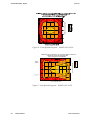
Spatial Response.................................................................................................................6-2
Explanation of the Operational Calculations ............................................................................6-2
Introduction ........................................................................................................................6-2
Description of Parameters Used in Calculations.................................................................6-2
Background Update ............................................................................................................6-5
Changing Background ........................................................................................................6-5
Calculation of the Monitoring Time (Tcal) ..........................................................................6-6
Minimum Detectable Activity (MDA) and High Background Criterion ............................6-7
Changing Conditions ..........................................................................................................6-7
Contamination Alarm .........................................................................................................6-8
Calculation of Activity and Uncertainty .............................................................................6-8
Quickscan ...........................................................................................................................6-9
Natural Background Reduction (NBR)...............................................................................6-9
Cobalt Coincidence Monitoring (CCM) .............................................................................6-9
Residual Contamination Level............................................................................................6-9
Automatic Calculation of Calibration Monitoring Time ..................................................6-10
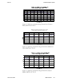
Isotope gamma efficiencies ........................................................................................................6-10
SAM12A – Standard Stainless Steel Liners .....................................................................6-11
Low Energy Variants ........................................................................................................6-11
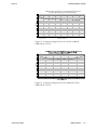
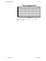
Typical 60Co detection performance .................................................................................6-12
Probability – Sigma and % ...............................................................................................6-12
Chapter 7
Technical Description - Circuitry......................................................... 7-1
Introduction..................................................................................................................................7-1
Controller Board - Type 5670A ..................................................................................................7-1
ETX Processor ....................................................................................................................7-1
PL30 Header for Non Volatile Memory (CF).....................................................................7-2
PL5 44 pin Primary IDE port for 2.5” disks .......................................................................7-2
x
SAM12 User Manual
Thermo Fisher Scientific
Issue: 1.0
Contents
PL25 40 pin Primary IDE port for 3.5” disks .....................................................................7-2
PL4 40 pin Secondary IDE port for CD Roms ...................................................................7-2
IC9 Programmable I/O Device ...........................................................................................7-2
IC6 and IC8 Buffer .............................................................................................................7-2
IC1 Sound Amplifier ..........................................................................................................7-2
IC2 & IC3 USB power controllers......................................................................................7-3
IC5 LCD Power and Control ..............................................................................................7-3
IC4 EEPROM .....................................................................................................................7-3
Display facilities .................................................................................................................7-3
Inputs ..................................................................................................................................7-3
Outputs................................................................................................................................7-3
Battery Controller Board Type 5660A.......................................................................................7-3
Introduction ........................................................................................................................7-3
Keyswitch operation ...........................................................................................................7-4
FHT681 42543-0223 & 42543-0224.............................................................................................7-4
Scintillation HV & Amplifier .............................................................................................7-4
HV & Amplifier Connections.............................................................................................7-5
Coincidence detector ..........................................................................................................7-5
Coincidence Detector connections......................................................................................7-6
Mains Power Supply Module ......................................................................................................7-6
LCD Display and Controller I/F & Backlight Inverter Module ..............................................7-6
General Electromagnetic Compatibility (EMD) Considerations.............................................7-7
Chapter 8
Routine Checks..................................................................................... 8-1
Mechanical Checks ......................................................................................................................8-1
Door Locking Mechanism (if fitted)...................................................................................8-1
SAM12 Mounting Arrangement .........................................................................................8-1
Other Mechanical Checks...................................................................................................8-1
Electrical Checks..........................................................................................................................8-2
Battery Charge state............................................................................................................8-2
Display Checks ...................................................................................................................8-2
EMC & Safety Earthing Checks .........................................................................................8-2
Periodic Source Checks ...............................................................................................................8-2
Regular Source checks.................................................................................................................8-3
Cleaning Instructions...................................................................................................................8-3
Chapter 9
Setting Up Procedure ........................................................................... 9-1
Initial Setting Up for Use.............................................................................................................9-1
General................................................................................................................................9-1
Initialisation ........................................................................................................................9-1
Setting Passwords ...............................................................................................................9-1
Setting the Operational Parameters.....................................................................................9-2
Selection of Detector Operating Parameters .............................................................................9-3
Detector HV Selection ........................................................................................................9-3
Derivation of the Optimum Operating Voltage ..................................................................9-4
Variance Testing ..........................................................................................................................9-7
Setting the NBR parameters ...............................................................................................9-8
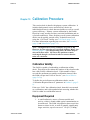
Chapter 10 Calibration Procedure ........................................................................ 10-1
Calibration Validity ...................................................................................................................10-1
Equipment Required..................................................................................................................10-1
Preparation for Calibration ......................................................................................................10-2
Calibration..................................................................................................................................10-2
Calibration for Other Nuclides .................................................................................................10-3
Calibration mixes..............................................................................................................10-4
Troubleshooting .........................................................................................................................10-4
If Background Values Vary by More Than 30% ..............................................................10-4
If Nuclide Count-Rate Outside Required Value ...............................................................10-4
Thermo Fisher Scientific
SAM12 User Manual
xi
Contents
Issue: 1.0
Chapter 11 Maintenance and Trouble Shooting .................................................. 11-1
Fault Messages ...........................................................................................................................11-1
Power-up Screens .............................................................................................................11-1
Self Test Screens...............................................................................................................11-1
Device Error Messages .....................................................................................................11-2
Operational Self Tests.......................................................................................................11-2
Servicing of the Electronics Chassis - Type 5689A .................................................................11-3
Removal of the Top Cover................................................................................................11-3
Removal of the Electronics Chassis from the Main Frame...............................................11-3
Removal and Replacement of the Power Supply..............................................................11-4
Battery - Removal and Replacement ................................................................................11-5
Battery Controller Board Type 5660A - Removal and Replacement ...............................11-5
Controller Board type 5670A - Removal and Replacement .............................................11-6
FHT681 cards - Removal and Replacement .....................................................................11-6
Removing & Replacing the Mains Inlet/Filter Assembly.................................................11-7
LCD Display, Touch Screen, Touch Controller & Backlight Inverter - Removal and
Replacement .....................................................................................................................11-8
Front/Rear Panel LED’s - Removal & Replacement .......................................................11-8
Start Switch, Keyswitch and Loudspeaker - Removal & Replacement ............................11-9
Detector Removal and Replacement ........................................................................................11-9
Removal............................................................................................................................11-9
Detector Replacement.......................................................................................................11-9
Setting up Replacement Detectors for Use .......................................................................11-9
Door Lubrication .....................................................................................................................11-10
Door Catch and Lock Replacement and Adjustment ...........................................................11-10
Replacement and Adjustment of (Chrome) Lever Catch................................................11-10
Replacement Door Stop Block .......................................................................................11-11
Trouble Shooting......................................................................................................................11-12
Normal Start-up (Boot-up) Operation.............................................................................11-12
Unit “dead” (will not boot up) & charging LED is OFF.................................................11-13
Unit “dead” (will not boot up) & charging LED is ON ..................................................11-13
Starts-up but Display is “Blank” & Fails Self Tests (no chimes) ...................................11-14
Will not run & displays “Out Of Service – Low Background Counts” ..........................11-14
Will Not Run & Displays “Out Of Service – High Background Conditions” ................11-15
Fails Lamp or LED Tests................................................................................................11-16
Fails Loudspeaker Test ...................................................................................................11-16
Fails the LCD Display Test ............................................................................................11-16
Display Backlight Failure ...............................................................................................11-17
Will Not Accept Valid Passwords ..................................................................................11-17
LCD Keypad Inoperative or Not Aligned.......................................................................11-17
Will not Enter Background Mode...................................................................................11-18
Locked in Background Mode .........................................................................................11-18
Locked in Measurement Mode .......................................................................................11-19
USB Output Data is Corrupted .......................................................................................11-19
Chapter 12 Spares List .......................................................................................... 12-1
Recommended Spares List ........................................................................................................12-1
Spares List ..................................................................................................................................12-2
Drawings List (by Assembly) ....................................................................................................12-3
Drawings List (Letter and Numerical Order) .........................................................................12-4
Accessories List ..........................................................................................................................12-4
xii
SAM12 User Manual
Thermo Fisher Scientific
Issue: 1.0
Tables
Tables
Table 1 Standard SAM12 Standard Stainless Steel Liners.......................6-11
Table 2 Low Variant SAM12 Energy Variants ........................................6-11
Table 3- Probability - Sigma and % .........................................................6-12
Table 4 - Summary of the Controller Board Inputs ................................11-18
Thermo Fisher Scientific
SAM12 User Manual
xiii
Figures
Issue: 1.0
Figures
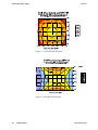
Figure 1 - Front Spatial Response ............................................................6-14
Figure 2 - Side Spatial Response..............................................................6-14
Figure 3 - Efficiency variation along Central Axis (Front to Back) SAM12A
4C-2D-1L .................................................................................................6-15
Figure 4 - Efficiency Variation along Central Axis (Bottom to Top)
SAM12A 4C-2D-1L.................................................................................6-15
Figure 5 - Efficiency Variation along Central Axis (Left to Right) SAM12A
4C-2D-1L .................................................................................................6-15
Figure 6 - Front Spatial Response - SAM12A 6C-1D-2L ........................6-16
Figure 7 - Side Spatial Response - SAM12A 6C-1D-2L..........................6-16
Figure 8 - Variation along Central Axis (Front to Back) - SAM12A 6C-1D2L .............................................................................................................6-17
Figure 9 - Variation along Central Axis (Bottom to Top) - SAM12A 6C-1D2L .............................................................................................................6-17
Figure 10 - Variation along Central Axis (Left to Right) - SAM12A 6C-1D2L .............................................................................................................6-18
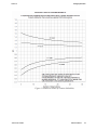
Figure 11 Statistical Limits of Counter Reliability.....................................9-9
xiv
SAM12 User Manual
Thermo Fisher Scientific
Issue: 1.0
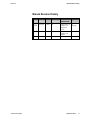
Manual Revision History
Manual Revision History
Issue
Thermo Fisher Scientific
Date
Name Section(s)
Revision
comments
Approval
1.0
Draft
14.09.07 C Hills All
Draft release of M
SAM12 User
Pottinger
Manual for
review
1.0
21.09.07 C Hills All
First release of
SAM12 User
Manual
C Ablett
SAM12 User Manual
xv
Issue: 1.0
Foreword
Foreword
Throughout this document the term “HEALTH PHYSICIST”
(HP) is used extensively. It refers to the Person, Persons or
Team responsible for setting up day-to-day running and
maintenance of the SAM12. This may be an Instrument
Maintenance Engineer, Radiation Safety Officer, local
“Competent Person”, Departmental Manager or any other
Responsible Person. The “HEALTH PHYSICIST” is the
highest-level security role, uniquely responsible for setting and
maintaining all lower order passwords. The HP would
normally be responsible for installing and setting up the
SAM12, calibrating for user-defined nuclides, programming
operating parameters and verifying correct operation of the
instrument.
The term “TECHNICIAN” is used to refer to the personnel
who normally repair and maintain the instrument in working
condition. IMP personnel are designated to this role.
Personnel who are general users of the system and normally
carry out routine diagnostic and test functions are allocated to
the “THERMOFISHER” role.
The term “USER” refers to anybody associated with or
operating the instrument in any way.
For more information on which menu options are available, see
Menu Roles (page 5-5).
Thermo Fisher Scientific
SAM12 User Manual
i
Issue: 1.0
Introduction
Chapter 1
Introduction
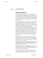
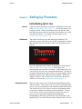
Small Articles Monitor
The Small Articles Monitors type SAM12 is designed for
monitoring gamma contamination of various items including
tools, clothing and personal effects and may also be used for
waste. Door switches and a start button are used in conjunction
with a back-lit touch-screen LCD, large area coloured lamps
and distinctive audible tones, to make controlled monitoring
fast and simple.
The outward appearance is similar to that of a safe, with a user
control and display panel mounted above the hinged door(s).
The electronics is housed in a compartment on top of the
instrument for easy maintenance. One or two inch (25mm or
50mm) thick lead shielding, screens the detectors and internal
measurement volume from background radiation.
Four, or optionally six, large area plastic scintillation detectors
are situated on the top, bottom, left and right and optionally
front and back sides of the sensitive volume. Each detector has
a separate, independently adjustable High Voltage (HV)
supply. Five discriminators are available per detector. This
provides adjustable windows for measuring different energy
levels. A removable stainless steel liner forms the internal
measurement volume. A low density liner is used in the lowenergy version.
A Mains power supply charges a 12 volt sealed lead-acid
battery to power the instrument and provides at least eight
hours operation in the event of mains failure. User definable
passwords protect all system parameters, which are accessed
through the touch-screen keypad.
The instrument security is protected by the presence of a USB
security dongle. In addition to the dongles, User-definable
passwords protect all system parameters, which are accessed
through the touch-screen LCD.
Operational parameters are user programmable and stored on
the instrument’s hard drive. In addition, all operational
parameters, including calibration and HV Scan data, are backed
up on an internal compact flash disk.
The system performs self tests at power-on and at regular
intervals during background acquisition. When not actively
engaged in monitoring, the system continuously acquires,
Thermo Fisher Scientific
SAM12 User Manual
1-3
Introduction
Issue: 1.0
analyses and stores background counts for each detector. All
counts are corrected to compensate for the “dead-time” of the
electronics. In measurement mode, background is
automatically subtracted and the result clearly shown by
audible and visual indicators. Options include a “Residual
Contamination” check which can be performed after an alarm,
if required and an “Auto Recount” can be performed if the
initial measurement produced an alarm condition. Two-door
variants can be programmed to lock after alarms if required.
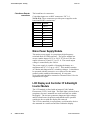
The standard SAM12 can have the following options in any
combination:
4
or
6
Scintillation Counters (C)
1
or
2
Doors (D)
1′′ (25mm)
or
2′′ (50mm)
Lead (L)
The instrument build standard is therefore identified using the
following nomenclature:
SAM12A – nC – nD – nL{-E}
An additional suffix of which signifies the user language may
also be used e.g. –E for English speaking or –C for Chinese.
A Low-energy version using a plastic liner is available for
detection of low-energy gamma emissions, including those
which accompany some primary alpha emitters. Identified by
the nomenclature SAM12L – nC – nD - nL
See Specification (page 3-1) for further information.
Note: At the time of printing, neither 1 inch nor low energy
versions of the SAM12 are available.
1-4
SAM12 User Manual
Thermo Fisher Scientific
Issue: 1.0
Description
Chapter 2
Description
Main Frame Type 5568A
The Main Frame, type 5568A, is manufactured from a sturdy
fabricated steel construction. Mounted on top of the main
frame is the Electronics Chassis, containing the Controller
Board, Battery and Battery Controller Board, two or three HV
and Amplifier Boards, a single Coincidence detector card, user
interface connections, user control, keyswitch and LCD display
with touch screen.
The inside of the frame is clad on all sides, including the doors,
with either 25mm (1") or 50mm (2") of lead to minimise the
effect of background radiation.
The scintillation detectors are mounted on the faces and doors
of the cabinet. A stainless steel liner fits inside the cabinet to
form a sealed cubicle which covers and protects the detectors.
A further stainless steel liner covers the lead on the inside of
the doors. The outside of the cabinet is clad with stainless steel
in-fill panels. The whole cabinet stands on two box sections,
mounted one on each side and running front to rear. These box
sections provide access for a Fork Lift truck.
Scintillation Detector Type 5569A
Each of the six detectors, type 5569A, is a large area plastic
scintillator wrapped in foil and plastic, mounted in an
aluminium jacket. A photomultiplier tube is embedded in the
plastic. Connection to the dynode chain assembly, type 5462A,
mounted on the back of the tube, is via a light-tight gland. A
single coaxial cable provides high voltage for the tube and
carries the signals to the HV and Amplifier PCB via an MHV
connector.
Electronics Chassis Type 5689A
The Electronics Chassis, type 5689A, comprising of a Base
Plinth and Top cover, is mounted on top of the Main Frame.
Once the Top Cover is removed, four fixings allow the Base
Plinth to be detached from the Main Frame to facilitate easy
maintenance.
Thermo Fisher Scientific
SAM12 User Manual
2-1
Description
Issue: 1.0
The Electronics Housing contains the Controller Board, Battery
Controller PCB, two or three HV and Amplifier PCB's, the
mains power supply and the battery. An aperture in the lead
allows for cabling to the detectors and a cutaway section in the
frame houses the door switch.
Situated on the side of the Electronics Chassis is the Side
Control panel. This panel contains connections for the Mains
input, ON/OFF key-switch, Network and four USB interfaces.
The Electronics Chassis supports a top-mounted back-lit LCD
with touch-screen, an internal loud-speaker, status lamps on
both front and rear panels and a large Start button on the front.
Controller Board Type 5670A (5671A)
The Controller Board, type 5670A, is motherboard to an ETXPM(C) 800mHz Processor.
The ETX assembly contains 256 megabytes of ram and the real
time clock.
The motherboard interfaces directly to all other boards and
external devices in the system via numerous connectors (not all
are being used):
•
The application software is retrieved from a 30 gigabyte
(minimum) hard disk drive cabled via PL5. The drive
also provides non-volatile storage for all data.
•
4 x USB connectors, SK1-4 are routed to the user
interface panel on the side of the main chassis
•
4 x isolated relay outputs are available on PL16-19, two
which are used to switch the door solenoids.
•
4 x isolated inputs are available on PL24, 27, 28 and
29, two used to sense door status and two used to
monitor the status of the door locks
•
1 x network interface SK6 routed to the user interface
panel on the side of the main chassis
•
1 x CRT monitor connection on SK7
•
1 x LCD drive on PL6 (or SK1) with backlight driver
on PL7
•
1 x RS232 driver for LCD touch screen on PL22
•
1 x POWER connector PL13
•
1 x Loudspeaker connection for sound generator on
PL3
Additionally a plug-in assembly, type 5671A, further extends
serial communication to X-channel devices via the RS422
2-2
SAM12 User Manual
Thermo Fisher Scientific
Issue: 1.0
Description
protocol as well as providing an I2C bus for driving the LED
display(s).
DC-DC Converter Board Type 5675A
A proprietary DC-DC Converter pair produces regulated +5V
and ±12V outputs directly from the Battery Controller Board,
type 5660A. Power is then distributed to the Controller Board
5670A.
Battery Controller Board Type 5660A
The Battery Controller Board, type 5660A, manages the
charging of a 12 volt sealed lead-acid battery. The whole
electronics system is powered from the 5660A Board. The
5660A constantly senses the charge/discharge state of the
battery and controls the charging voltage accordingly. The
charging voltage is temperature compensated by means of a
thermistor located on the battery. This helps to maximise the
life time of the battery.
A momentary key-switch, located on the side panel, allows
power to be switched to the electronics provided the battery
voltage is above a safe value (i.e. not discharged), even when
mains power is absent. The key-switch needs to be held ON
for at least two seconds before the ON state is engaged.
The 5660A continues to monitor the terminal voltage of the
battery during battery operation but will signal a shut-down if
the battery discharges to a predetermined point, beyond which,
it would suffer permanent damage and be difficult to recharge.
A miniature fuse protects against over-current conditions.
The application software would normally regulate shut-down.
In the event of the software losing control an emergency shutdown is possible by holding the key-switch ON for a minimum
of 10 seconds (nominal).
FHT681 Scintillation HV and Amplifier Type
42543-0223
The Scintillation HV and Amplifier Board, type 42543-0223, is
a dual channel high voltage generator/scintillation amplifier
pair. The HV generators are sub-assemblies (type 42543-0202)
which are controlled by DACs (Digital to Analogue Converter)
on the main printed circuit board. The HV has a range between
0 and 1400 Volts, with a resolution of about 1 Volt.
The charge pulses arriving along the high voltage cable from
the detectors are amplified and each fed to five discriminators
Thermo Fisher Scientific
SAM12 User Manual
2-3
Description
Issue: 1.0
and five associated counters, all controlled by the
microprocessor on the main board.
The cards are interrogated via the X-channel bus to retrieve
counter values generated every 100ms from a 5 second buffer.
A digital output from each channel is fed to the CCM card, type
42543-0224, such that coincidence on any two detectors can be
registered. This allows measurements on Cobalt 60.
FHT681 Coincidence Detector Card Type
42543-0224
The card can support coincidence from 6 detectors via the
digital outputs of the HV Amps. By setting relevant summing
thresholds on the card, coincidence from two detectors only can
be supported.
The cards are set up and interrogated via the X-channel bus.
Visual Indicator LED PCB Type 5672A
This assembly provides the rear (and front optional) visual
display necessary to inform the user of progress through the
instrument.
2-4
SAM12 User Manual
Thermo Fisher Scientific
Issue: 1.0
Specification
Chapter 3
Specification
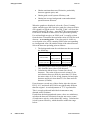
The standard SAM12 (with stainless-steel liners) is available
with three options, in any combination:
•
4 or 6 Scintillation Counters (C)
•
1 or 2 Doors (D)
•
1 or 2 inches (25mm or 50mm) of lead shielding (L)
Therefore, the SAM12 type nomenclature used to identify the
build standard is in terms of nC, Nd & nL. The eight variants
are:
•
SAM12A – 4C – 1D – 1L
•
SAM12A – 4C – 1D – 2L
•
SAM12A – 4C – 2D – 1L
•
SAM12A – 4C – 2D – 2L
•
SAM12A – 6C – 1D – 1L
•
SAM12A – 6C – 1D – 2L
•
SAM12A – 6C – 2D – 1L
•
SAM12A – 6C – 2D – 2L
A Low energy Plastic liner (LP) version is available for
detecting low-energy gammas, including those which
accompany some primary alpha emitters. It is restricted to the
variants giving maximum sensitivity and shielding, with a
choice of doors:
•
SAM12L – 6C – 1D – 2L, and
•
SAM12L – 6C – 2D – 2L
A further option is available depending on the character set
required by the Windows XP operating system.
•
-E
Western Europe/North America
•
-C
Chinese
An upgrade kit (AE0208A) is available to facilitate the
detection of the radionuclide 60Co.
Thermo Fisher Scientific
SAM12 User Manual
3-1
Specification
Issue: 1.0
Operational Parameters
See Params 1 (page 5-8), Params 2 (page 5-10) and Params 3
(page 5-11) for information regarding the settings and defaults
for the Operational Parameters.
Software Options
See Options (page 5-6) for information regarding the settings
and defaults for the Software Options.
Vault Options
See Doors (page 5-13) for information regarding the settings
and defaults for the Vault and Door Options.
Default Messages
See Messages (page 5-15) for information regarding the
settings and defaults for the Software Options.
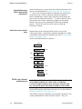
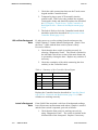
Background Capability
Background capability is related to alarm threshold and
statistical certainty requirements. Background subtraction is
included in the measurement routines for the detectors. When
the isotope of interest is of low energy level, the energy
window can be changed to lower the background count rate
thus allowing greater statistical certainty (see Hv Power (page
5-28) and Selection of Detector Operating Parameters (page 93)).
The mean background count rate for use in measurement
calculations is accumulated from a series of 10 second counts,
with a maximum of 10 results stored at any one time. The
mean background count rate is therefore based on a 100 second
count, which is maintained on a “rolling average” basis.
A significant change in the measured background count rate
from the mean will cause the SAM12 to discard the current
mean value and restart background monitoring (see Changing
Background (page 6-5)).
If, due to heavy use, the SAM12 has been unable to measure
background for 15 minutes, a 1 second background count is
performed immediately after the current monitoring sequence.
If no significant change is detected, the machine will be
available for further monitoring. If a change in background is
detected, further background measurements are performed until
3-2
SAM12 User Manual
Thermo Fisher Scientific
Issue: 1.0
Specification
the SAM12 detects a stable background (see Changes to the
Normal Background Monitoring (page 5-49)).
When the mandatory 100 second background count has been
accumulated, the monitoring time required to achieve the
specified alarm level is calculated. Providing the monitoring
time calculated falls within the maximum and minimum limits
(see Params 2 (page 5-10)), the instrument will be ready for
monitoring. If, however, the monitoring time calculated is
greater than the maximum allowed, a “high background”
condition exists and monitoring will be inhibited.
A high background condition indicates that the alarm level set
and statistical certainties required are not achievable, under the
current background conditions. This may be overcome when
either the background falls or more suitable operational
parameters are entered by the Health Physicist. It is advisable
to check for residual contamination if this occurs unexpectedly
or persists.
The lower the background field the more sensitive, stable and
accurate the measurements will be.
Detectors
Four or Six Detectors
Type:
5569A
Construction:
Large area scintillation counter using a plastic
phosphor type BC408 wrapped in foil, plastic and a
aluminium jacket.
Thickness:
2.25" (57 mm)
Area:
15" (381 mm) x 15" (381 mm) = 225"sq (145,161
mm2)
Photomultiplier:
1" (25 mm) extended cathode
Shielding:
1" (25 mm) or 2" (50" mm) of aged lead on all
external faces
Energy
Response
20 keV upwards (minimum detectable depends on
liner material)
Detector HV settings
Operating voltages should normally be set up using the NBR
method, although they may also be set up using the Figure of
merit (S2/B shown in figure 9.1) to yield the operating
Photomultiplier voltages. These settings are determined and set
using the HV Scan feature (Calibration|HV Scan (see HV Scan
(page 5-25)). The recommended values, based on the NBR
optimization method, can be found in the Calibration certificate
for each individual instrument.
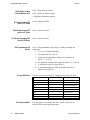
Energy Window
This can have all thresholds adjustable under software control:-
Thermo Fisher Scientific
Programmable Threshold 1
0 - 4095mV in 1 mV steps
Programmable Threshold 2
0 - 4095mV in 1 mV steps
SAM12 User Manual
3-3
Specification
Issue: 1.0
Programmable Threshold 3
0 - 4095mV in 1 mV steps
Programmable Threshold 4
0 - 4095mV in 1 mV steps
Programmable Threshold 5
0 - 4095mV in 1 mV steps
Control
Instrument ON/OFF operation is via a momentary key-switch
on the side panel. Operating any door activates a micro switch
and suspends background monitoring. Closing the door
indicates a sample is ready to be monitored and initiates a timeout period. If the Start button is pressed within the time-out
period, the article is monitored, otherwise background
monitoring is resumed. Opening any door during monitoring
aborts the measurement. Optional door locks are available and
will activate to prevent any contaminated item being removed
from the clean door. Data entry and diagnostic functions are
accessed through a touch screen but access is password
protected.
Displays
LCD
Lamps
The integral back-lit LCD display provided is used in
conjunction with the touch-screen for data entry and diagnostic
functions. As well as duplicating any front panel LED display,
the LCD can also provides comprehensive, user-friendly
operational guidance, measurement results and instrument fault
messages.
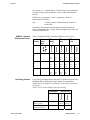
Five, bright, rear (optional front) panel lamps show the
instrument status at all times and give the user clear indication
of the measurement result.
FRONT
Charging LED
BACK (2-door only)
Green:
Ready / Clear
Ready / Clear
White:
Recount
Recount
Yellow:
Count
Count
Red:
Alarm
Alarm
Blue:
Out of Service
Out of Service
A pulsing white LED on the side panel indicating that the
mains is on and charging the battery.
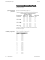
Audible Indications
3-4
SAM12 User Manual
“Chime”
Measurement with a “CLEAR” result
“Single Beep”
End of a parameter counting sequence.
Thermo Fisher Scientific
Issue: 1.0
Specification
“Periodic Beeps”
Operator sequence “ERROR”
Door opened when Background required
Door open too long
“Rapid Beeps”
Measurement exceeding “ALARM ACTIVITY”
“Siren”
Measurement exceeding “HIGH LEVEL ALARM”
“Warble”
Measurement Aborted
The speaker volume is user adjustable under software control.
Network Communications
An RJ45 connector provides for compliance with IEEE 802.11
USB Ports
A four port USB (version 1.1) hub is available on the side panel
for peripheral interfaces (such as memory sticks, dongles,
keyboard, mouse, etc.)
Printers
A dot matrix printer is available as an option (A0210A).
Contact Thermo Fisher Scientific for the latest model.
Power Requirements
Voltage
-
85 to 264 volts AC
Frequency
-
47 to 63 Hz
Maximum power
-
65 V.A.
Circuit Protection
-
Integral mains fuse in Power supply 250V 2 A
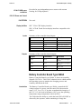
Battery Backup
Battery type:
Sealed lead-acid
Battery capacity:
12 volts 15Ah
Battery support:
typically better than 8 hours
Battery Fuse
5 x 20mm 6.3Amp quick acting.
Dimensions
Overall Dimensions 5568A + 5689A
Thermo Fisher Scientific
Height
46”
(1170 mm) approximately (all versions)
Width
29"
(737 mm) approximately (max for 2-door versions
Depth
36.25"
(921 mm) approximately including door handles,
two door unit.
33.25"
(844 mm) approximately including door handle,
(6C-1D-2L)
SAM12 User Manual
3-5
Specification
Dimensions of Measuring
Volume
Weight - with 1" (25 mm) of
lead shielding, 4 detectors
and one door
Weight - with 2" (50 mm) of
lead shielding, 6 detectors
and two doors
Issue: 1.0
Height
15"
(381 mm)
Width
15"
(381 mm) – 2.34 cubic feet (66 Litres)
Depth
18.3"
(466 mm) – Single door – 2.38cc(68L)
Depth
20.1"
(510 mm) – Double door – 2.60cc(74L)
SAM12A-4C-1D-1L
770 Kg (1697 LB’s) Packed.
670 Kg (1477 LB’s) Nett Weight.
SAM12A-6C-2D-2L
1480 Kg (3263 LB’s) Packed.
1380 Kg (3042 LB’s) Nett Weight.
Environmental
Temperature and Humidity
Operational Temperature Range
+0°C to +45°C (32°F to 113°F
Storage Temperature Range
-10°C to +50°C(14°F to 122°F
Humidity Range
up to 95% RH non condensing
NOTE:
USE BELOW +0°C (32°F) IS NOT RECOMMENDED –
THE LCD DISPLAY WILL BECOME “SLUGGISH”
BELOW THIS TEMPERATURE.
DO NOT STORE ABOVE +60°C (122°F)
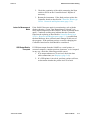
Magnetic Shielding
Internal fields – from measured items:
Standard SAM12 Internal magnetic shielding ensures
magnetic fields of up to 9000 A/m
‘A’ variants
measured on the surface of the liner will
have an effect of less than 5% on the
count rate of the adjacent detector.
Low energy
SAM12 ‘L’
variants
Internal mu-metal magnetic shielding is
not fitted in the Low-energy variants to
maximise the low energy gamma
sensitivity. Thus, the magnetic
immunity will be reduced.
For more information regarding SAM12 variants, see
Specification (page 3-1.)
External fields – all variants:
Large external magnetic fields may reduce the measured value.
3-6
SAM12 User Manual
Thermo Fisher Scientific
Issue: 1.0
Specification
IP rating
IP50
Environmental restrictions
•
Not for use in flammable or explosive atmospheres
•
For installation in “drip-free” locations only
•
Do not expose to excessive dust pollution levels
Thermo Fisher Scientific
SAM12 User Manual
3-7
Issue: 1.0
Unpacking and Installation
Chapter 4
Unpacking and Installation
Unpacking
After installation of 2-door SAM12, ensure both doors are
closed before switch-on.
WARNING:
DUE TO THE LEAD SHIELDING THE SAM12
WEIGHS 1.5 TONS. A FORK-LIFT TRUCK OF
SUITABLE LIFTING CAPACITY MUST BE USED
TO MOVE AND TRANSPORT THE SAM12
SAFELY, USING THE INTEGRAL FORK-LIFT
CHANNELS. WHEELS, SKATES, SKIDS OR
SIMILAR DEVICES MUST NOT BE USED TO
MOVE THE SAM12.
PARTICULAR CARE SHOULD BE TAKEN ON
GRADIENTS
ENSURE THE INSTALLATION SITE IS
SUITABLY ROBUST
DO NOT ATTEMPT TO OPEN DOORS UNTIL
THE TRANSIT SUPPORTS HAVE BEEN
REMOVED (see Removing Door Transit Supports
(page 4-3)).
The SAM12 case should contain the following:
To unpack the SAM12
Thermo Fisher Scientific
•
Small Articles Monitor (SAM12)
•
1 or 2 Door Handles
•
Combined Operational and Maintenance
Manual
•
Pack containing ON/OFF keys, Dongle and
Screen Cleaner
•
Calibration Certificate
•
SAM12 Mains power cord (EC countries
only)
•
Printer with printer cable
Printer Tractor Feed
Plastic locating tray
(Optional)
•
Mounting plinth AE0181B
(Optional)
Remove the top and side packing panels and peel off the
polythene wrapping.
SAM12 User Manual
4-1
Unpacking and Installation
Issue: 1.0
The door handle(s), manual, Calibration certificate, Keys,
Dongle and Mains power cord are packed inside the
measurement cubicle.
The Printer (if supplied) is packed in a separate carton. The
printer, printer cable and mains leads are packed inside the
measurement cubicle. Retain the packing for these items.
Remove the protective foam from the outer edge of the
stainless steel liner and door plate. It may be necessary to
remove any traces of adhesive with a suitable solvent cleaner.
The SAM12 should be left on the base pallet until it is at the
installation site in order to reduce the risk of damage during
transportation. The wooden base is designed to allow easy
fork-lift access.
The floor of the installation site should be level, even and
suitably robust in order to support the weight of the SAM12.
When at the installation site, remove and retain the plinth
mounting bolts and fixings. Lift the SAM12 off its wooden
base using the fork lifting channels provided.
CARE MUST BE TAKEN WHEN LIFTING - THE
SAM12 WEIGHS 1.5 TONS.
Mechanical installation is described below.
Mechanical Installation
Positioning and Mounting
the SAM12
WARNING:
DO NOT ATTEMPT TO OPEN DOORS UNTIL
THE TRANSIT SUPPORTS HAVE BEEN
REMOVED (see Removing Door Transit Supports
(page 4-3)).
The SAM12 is intended for indoor use only, and should not be
used where liquids can drip or be spilled onto the lid.
For best possible performance it is suggested that the SAM12
be positioned in the lowest stable background surroundings.
High background fields will reduce sensitivity and fluctuating
backgrounds may cause false alarms and operational delays
during background update periods.
The SAM12 has no specific ventilation requirements.
The SAM12 should be placed on as flat a surface as possible as
no means of levelling adjustment is provided on the cabinet.
Installation on a slope may affect operation of the door and
make opening awkward. Before finally positioning the
SAM12, it will be necessary to remove the four M10 transit
bolts securing it to the wooden base - leave the door transit
supports in place until the SAM12 is physically installed.
4-2
SAM12 User Manual
Thermo Fisher Scientific
Issue: 1.0
Unpacking and Installation
Retain the four plinth bolts for future use. Use a fork lift of
suitable capacity to lift the SAM12 off the wooden base and
finally position it.
Ideally the SAM12 should be mounted on a raised “plinth”
(base) in order that the door and cubicle are at optimum
operating height for users and the LCD display at the optimum
viewing angle.
Any such plinth must be flat, suitably robust, mechanically
sound, stable and fixed to the floor. The SAM12 should be
fixed to the plinth.
A SAM12 mounting plinth is manufactured – associated
equipment order code AE0181B. When using this plinth, the
SAM12 should be secured to it using the four set of M10 fixing
bolts previously removed from the wooden transit base. The
mounting plinth (base) should in turn be secured to the floor
using the four 12mm diameter mounting holes with suitable
fixings. Plinth details are shown on drawing B91208.
Once the SAM12 is correctly positioned, install the optional
plastic location tray within the measurement cubicle.
Removing Door Transit
Supports
Only remove the door transit supports when the SAM12 is
physically installed – to avoid fork lift shock damage.
The SAM12 is shipped with a “Transit Support” located on the
underside of each door. The Transit Supports are bolted
through the main frame and door frame, to support the door and
protect the hinges and latching/locking mechanism from
physical damage due to rough transit handling.
Do not attempt to open the door(s) until the Transit
Support(s) have been removed.
The Transit Support is secured to the main frame with four M6
Hex head bolts to the latch end of the door frame with one
further M6 Hex head bolt on the underside of the door frame at
the latch end.
Remove all five fixings before opening the door. Check that
the top of the latch cut-out in the doors clears the top of the
aluminium catch block by at least 2mm. If this clearance is less
than 2mm, transit damage is likely - do not use the SAM12
before contacting Thermo Fisher Scientific or your local agent
for further advice. See Door Catch and Lock Replacement and
Adjustment (page 11-10) for further information.
The Door Transit Supports are “unique” to each door (they
bear the SAM12 Serial No. and “F” for the front door,
where applicable) and so should be retained for future use
Thermo Fisher Scientific
SAM12 User Manual
4-3
Unpacking and Installation
Issue: 1.0
when transporting the SAM12 over any distance or in
situations when rough handling is possible.
Fitting the Door Handle(s)
The SAM12 is shipped with the door handle(s) removed and
packed inside the measurement cubicle.
Remove the protective packaging and fix the handle(s) securely
to the front left-hand ledge of the door frame using the M6 and
M8 hex head bolts and washers supplied – these are shipped
screwed into the door frame(s).
Note that the Door Handle (no longer reversible) is
deliberately oriented biased “inboard” of the door, such
that the main tube is in direct vertical alignment with the
Door Latch Lever. (This limits the travel of the latch lever
and prevents excessive force damaging the latch. It also makes
single hand door operation equally easy for Left-handed and
Right-handed users). Previously, incorrect installation resulted
in excessive latch wear and premature failure.
Door Operation
Check for smooth operation of the door latching/de-latching
mechanism. If any adjustment is necessary, refer to
Replacement and Adjustment of (Chrome) Lever Catch (page
11-10) – after the Electrical Installation (page 4-5) is complete.
NOTE: The doors are a fabricated and welded
construction which will not be manufactured exactly
“square”. Some “out of square” deflection will also result
from loading the lead, particularly 2" (50mm) models.
Additionally, uneven compression of the rubber seal may
make the door appear “out of square” or to “sag”. Any
manufacturing tolerances are allowed for and compensated
by the hinge mounting and door catch adjustment during
final door Mounting/Assembly.
In-built door catch adjustment of ¼" (6mm) exists to
accommodate any movement or wear that may take place see Door Catch and Lock Replacement and Adjustment (page
11-10). Therefore, a door which is, or appears to be, “out of
square” is in no way an indication of manufacturing defect
or mechanical failure. If a door does not operate correctly
consult Door Catch and Lock Replacement and Adjustment
(page 11-10).
The mechanical installation is now complete.
After approximately the first two weeks or 2,000 operations
check the door hinge and locking mechanisms for initial
4-4
SAM12 User Manual
Thermo Fisher Scientific
Issue: 1.0
Unpacking and Installation
“bedding-in” adjustments as described in Door Locking
Mechanism (if fitted) (page 8-1).
Electrical Installation
Before proceeding with the electrical installation, ensure the
SAM12 has been mechanically installed as described in
Mechanical Installation (page 4-2).
IMPORTANT:
Battery State
Electrical Installation
ENSURE CORRECT ELECTRICAL SUPPLY
AND MAINS CONNECTOR WIRING FOR
YOUR MAINS SUPPLY.
SAM12 is shipped with the lead-acid battery discharged.
The SAM12 is fitted with a 50 VA auto ranging power supply
requiring a maximum input power of 65 VA.
DO NOT CONNECT THE MAINS SUPPLY. ENSURE
THE KEYSWITCH ON THE REAR PANEL IS SET TO
THE OFF POSITION.
A standard IEC mains connector is fitted on the side panel,
specified to IEC 320, EN60320. Only mating connectors of the
SAM12 standard should be used.
The SAM12 must be connected to a fused outlet capable of
being isolated. The isolation switch should be close to the
monitor and within reach of the operator.
The IEC power cord must be connected to the electricity supply
as follows:
Brown conductor
to LIVE ‘L’
or Red terminal
Blue conductor
to NEUTRAL ‘N’
or Black terminal
Green/Yellow
conductor
to EARTH ‘E’
GROUND
or Green/Yellow
terminal
WARNING: THIS EQUIPMENT MUST AT NO TIME BE
OPERATED WITHOUT THE GREEN WIRE CONNECTED
TO THE MAINS GROUND.
When all installation work has been carried out, follow the
setting up procedure described in Setting Up Procedure (page
9-1).
Thermo Fisher Scientific
SAM12 User Manual
4-5
Unpacking and Installation
Issue: 1.0
Printer Installation
Unpack the Printer (if supplied) and locate it as required in the
vicinity of the SAM12. Configure the printer as detailed in the
manufacturers hand book.
ENSURE the printer is set to the relevant mains setting.
The printer should be used with the USB interface, simply by
connecting to the SAM with the USB cable supplied.
Notes on Orientation and Positioning
The large area detectors of the SAM12 make it very sensitive to
changes in background. Therefore, it is recommended that the
installation site be chosen for background stability and to
minimise the effect of statistical fluctuations.
It is recommended that the SAM12 be installed away from
active areas to suit both these needs.
If the background field at the installation site is directional it is
recommended that the SAM12 be installed so that the back of
the Cabinet faces the field source. This orientation should
minimise the penetration and scatter of background radiation
around the door aperture, although the advantage is small.
After Installation of 2-door SAM12s, ensure both doors are
closed before switch-on.
4-6
SAM12 User Manual
Thermo Fisher Scientific
Issue: 1.0
Operating Instructions
Chapter 5
Operating Instructions
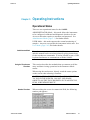
Operational States
There are two operational states for the SAM12:
ADMINISTRATOR Mode – this mode allows the instrument
to be configured, calibrated and diagnostic checks to be run.
Access to this state requires a username and password. See
Administrator Mode (page 5-1) for further details.
USER Mode – this mode supports the normal monitoring of
samples. Any user can operate the instrument in this state. See
User Mode (page 5-45) for further details.
Administrator Mode
Using the Touchscreen
Functions
Note that communications with the SAM12 is via a touchscreen
and this manual has been written primarily giving instructions
for the touchscreen commands. It is also possible to use a USB
keyboard and mouse to communicate with the SAM12.
This section describes the methods that are common to all the
entry and data viewing operations in the Parameter Mode
menus.
When using the touchscreen, directly touch the menu options
on the screen when selecting a function.
CAUTION: IT IS ADVISED TO USE A CLEAN FINGER
TO TOUCH THE SCREEN. DO NOT USE SHARP
OBJECTS ON THE TOUCHSCREEN SUCH AS PENCILS,
PENS, SCREWDRIVERS ETC.
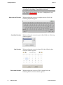
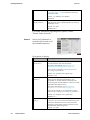
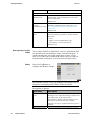
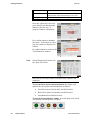
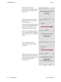
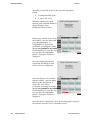
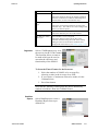
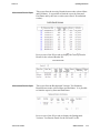
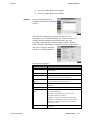
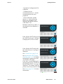
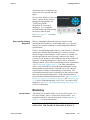
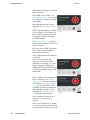
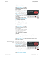
Number Functions
Thermo Fisher Scientific
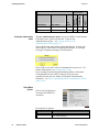
When touching the screen in a numerical field, the following
number pad appears:
SAM12 User Manual
5-1
Operating Instructions
Issue: 1.0
Note that the Function Name, minimum and maximum values
are displayed depending on the function selected.
If an illegal value is entered, the value is highlighted in red:
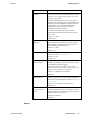
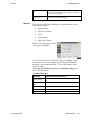
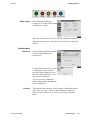
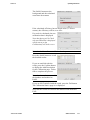
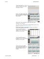
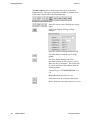
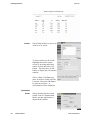
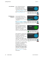
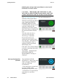
Alpha-numerical Functions
Pre-defined Functions
Date Functions
File Location Functions
5-2
SAM12 User Manual
When touching the screen in an alpha-numerical field, the
following keyboard appears:
When touching the screen in a pre-defined field, the following
window appears:
When touching the screen in a date field, the following date
selection window appears:
When touching the screen in a File Location field, the
following Drive selection window appears:
Thermo Fisher Scientific
Issue: 1.0
Operating Instructions
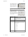
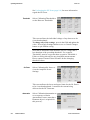
Button Types
The Button types are listed below:
Direction Arrows steps through the menu
options
Drop-down lists allows you to select a predefined option from the list.
Action button show the process taken when
selected.
Tick Boxes show independent options that you
can choose to set, or mark. The choice can be
toggled on and off by touching on the box.
Radio Buttons show mutually exclusive
options; choosing one option automatically
clears the others. The black dot shows the
selected option.
Note that changes made to fields are
highlighted until applied or cancelled.
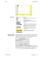
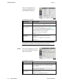
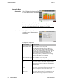
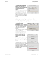
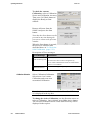
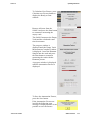
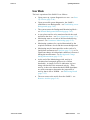
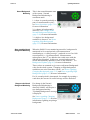
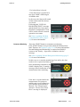
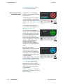
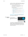
Gaining Access to the
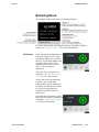
Administration Mode
Administration mode is entered by pressing on 'SAM12' in the
bottom left-hand corner of the touchscreen when the SAM12 is
in Background Checking mode. The Entering Admin Mode
window is displayed requesting to select a User:
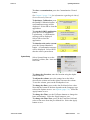
To select a different user to the one displayed, press the User
field of the touchscreen. Select Health Physicist, Technician or
ThermoFisher using the Up/Down arrow and select OK. See
Foreword (page i) for more information regarding the roles.
Thermo Fisher Scientific
SAM12 User Manual
5-3
Operating Instructions
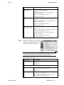
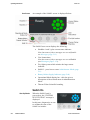
Issue: 1.0
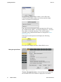
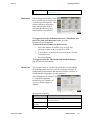
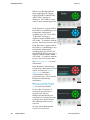
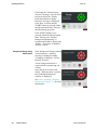
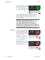
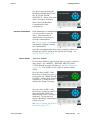
In the Entering Admin Mode window, select OK for the
ENTER PASSWORD window (see below) and the Alphanumeric keyboard to be displayed:
Enter the password using the keyboard and select OK to enter
the Administration Mode – note that the Diagnostics – Detector
Bar window is initially displayed. The various options
available in the Administration Mode are displayed in Menu
Roles (page 5-5).
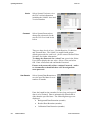
Entering an invalid password will display the following
message:
Press OK to re-display the Enter Admin Mode screen.
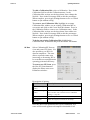
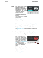
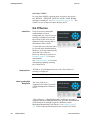
Moving through the Menus
To move through the menus, select the Main menu option on
the left-hand side of the window to display the sub-menus
5-4
SAM12 User Manual
Thermo Fisher Scientific
Issue: 1.0
Operating Instructions
available. Then select the sub-option from the top. Note that a
full list of menu and sub-menu options is displayed in Menu
Roles below.
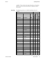
Menu Roles
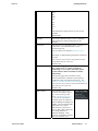
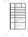
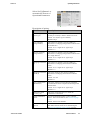
The following options are available depending on the role
selected:
Sub-menu
See
Page
Health
Physicist
Set-Up
Options
5-6
√
√
Params1
5-8
√
√
Params2
5-10
√
√
Params3
5-11
Alarms
5-12
√
√
Doors
5-13
√
√
Battery
5-14
Messages
5-15
√
Detectors Bar
5-16
√
√
√
Information
5-16
√
√
√
Timed Counts
5-17
√
√
Variance Test
5-17
√
√
Vault
5-18
√
Battery Charger
5-19
√
Efficiencies
5-19
√
√
√
Cal Check
5-19
√
√
√
Calibration
Selection
5-24
√
√
HV Scan
5-25
√
√
Thresholds
5-28
Hv Power
5-28
√
Attenuation
5-28
√
Setup
5-30
√
Information
5-30
√
Diagnostics
5-31
√
Reports
5-31
√
√
Archives
5-40
√
√
Actions
5-40
√
√
Setup
5-41
√
√
Version
5-42
√
√
Passwords
5-42
√
√
Calibration
CCM
Data
System
Thermo
Fisher
Main Menu
Diagnostics
Thermo Fisher Scientific
Technician
Role Name
√
√
√
√
√
√
√
√
√
√
SAM12 User Manual
5-5
Operating Instructions
Issue: 1.0
Exiting the Administration
Mode
Data Retention
5-42
√
√
Interfaces
5-43
√
√
Thermo
Fisher
Sub-menu
See
Page
Health
Physicist
Main Menu
Technician
Role Name
To exit Administration mode, press on 'SAM12' in the bottom
left-hand corner of the touchscreen. Login to the
Administration mode – see Gaining Access to the
Administration Mode (page 5-3).
Select the System main menu option and then the Actions submenu option. Select the Exit Application button. A warning
message is displayed asking for confirmation:
Select OK to exit and Cancel to abandon the exit process. For
further information, see Actions (page 5-40).
Upon exiting from the Keypad Parameter Mode, a Residual
Contamination check will be enforced if the previous
operational state was an Alarm or Residual Contamination
condition – see Notes regarding Residual Contamination Check
(page 5-60).
Setup Menu
Options
Select Set-Up|Options to
customise the SAM12's
operation:
Description of options:
5-6
SAM12 User Manual
Field Name
Description
Default Units
Use the pre-defined window to select a unit from
one of the following:
Thermo Fisher Scientific
Issue: 1.0
Operating Instructions
dpm
Bq
kBq
pCi
nCi
μCi
mCi
Ci
This changes the displayed activity units for the
SAM12.
Default: dpm
Language
Use the pre-defined window to select a language.
This changes the displayed language for the
SAM12.
Quick Scan
This option may be enabled to allow “real-dirty” or
“real-clean” to be identified before end of
monitoring period.
Also see Quick Scan Period in Params 2 (page 510).
QuickScan is disabled during automatic and manual
recounts.
Note that it is not possible to tick Quick Scan and
CCM Enabled at the same time.
Default: OFF
CCM Enabled
If this option is greyed out, then your SAM12 is
not configured to use Cobalt Coincidence
Monitoring. If you require this utility, please
contact Thermo Fisher Scientific for further
information.
This option toggles the CCM menu on/off.
If the CCM board is installed, tick this option to
enable the Cobalt Coincidence Monitoring. See
Cobalt Coincidence Monitoring (CCM) (page 6-9).
Note that it is not possible to tick CCM Enabled and
Quick Scan at the same time.
Default: OFF
NBR Enabled
Note that this option is not
available until High Voltages
are selected during an HV
Scan – see HV Scan (page 525) for further information.
Tick this option to enable the
Natural Background Reduction
(NBR). This will enable NBR
algorithms to be used to
determine the proportion of
activity that is due to Naturally
Occurring Radioactive
Material (NORM). If the
presence of NORM is detected,
then an estimation of its
Thermo Fisher Scientific
SAM12 User Manual
5-7
Operating Instructions
Issue: 1.0
activity shall be made and
subtracted from the total
activity to give a figure for
artificial activity which will be
displayed along with the total
activity value.
Default: OFF
Auto Recount
Tick this option to enable an automatic recount to be
performed before a result if the following is true:
High Level Alarm > measurement > Normal Alarm
Default: OFF
Manual Recount
Tick this option to allow the user to initiate a
recount after a measurement has been completed but
before the door is opened and the article is removed.
Default: OFF
Residual
Contamination Check
after Alarm
Tick this option to enable a Residual Contamination
Check to be automatically performed following an
Alarm. For further information regarding Residual
Contamination Checks, see Residual Contamination
Check (page 5-59).
Residual
Contamination Check
before Background
Check
Tick this option to enable a Residual Contamination
Check to be automatically performed before Normal
Background Monitoring commences. See Normal
Background Monitoring (page 5-49).
Default: OFF
Show Uncertainty
Value on Result
Note that the "Show Uncertainty Value on Result"
and "Show Activity Result" option combine to
display the information on the result screen.
When this option is ticked, the Uncertainty value is
included in the result if the Activity is also
displayed. See Monitoring Result (page 5-55) for
more information.
Default: OFF
Show Activity Result
Click on one of the radio buttons to select one of the
following:
Never – the Activity Value will not appear in the
result screen
On Alarm – the Activity value will only be
displayed if an alarm occurs
On All – the Activity Result will be displayed for all
results.
See Monitoring Result (page 5-55) for more
information.
Default: Never
Params 1
5-8
SAM12 User Manual
Thermo Fisher Scientific
Issue: 1.0
Operating Instructions
Select Set-Up|Params1 to
customise the first set of
Operational Parameters:
Description of options:
Field Name
Description
Low- Background
Alarm (cps)
If a background measurement falls below this value
(counts per second), a detector failure will occur.
Values: 0 to 99,999 cps (0 to disable)
Default: 50cps
Gross Changing
Background (σ)
This statistical variable is used by SAM12 to
determine if a changing background condition exists
on all detectors.
Values: 0.1 to 7 sigma in 0.1 sigma steps
Default: 5 σ
Detector Changing
Background (σ)
This statistical variable is used by SAM12 to
determine if a changing background condition exists
on a single detector.
Values: 0.1 to 7 sigma in 0.1 sigma steps
Default: 7 σ
Changing Conditions
(σ)
This statistical variable is used by SAM12 to
determine if a changing measurement condition
exists.
Values: 0.1 to 7 sigma in 0.1 sigma steps
Default: 7 σ
Changing Conditions
Period (s)
This is the length of time used by SAM12 to
determine if a changing measurement condition
exists.
Values: 2 to 30 s
Default: 3 s
RCC Contamination
Threshold (σ)
This is the statistical increase during a Residual
Contamination Check compared to the background
measurement.
Values: 0.1 to 7 sigma in 0.1 sigma steps
Default: 7 σ
Calibration Check
Accuracy (%)
This is the required accuracy to which the
calibration is carried out.
Default Calibration
Source
Use the pre-defined window to select a default
source. For a list of Sources, see Cal Check (page
5-19).
Values: from source database
Calibration Required
Interval
Thermo Fisher Scientific
This is the number of days since that last calibration
date before the unit needs to be calibrated again.
See Out of Calibration (page 5-48) to view the
SAM12 User Manual
5-9
Operating Instructions
Issue: 1.0
message displayed on the unit when out of date and
Cal Check (page 5-19) for information of the last
Calibration Date.
Values: 1 to 400 days (0 to disable)
Default: 0
Max Clear-Result
Display Time (s)
This is the maximum length of time (in seconds)
that the Clear result is displayed before reverting to
the Ready screen.
Values: 0 to 500 s
Default: 300 s
For further information regarding these options, contact
Thermo Fisher Scientific.
Params 2
Select Set-Up|Params2 to
customise the second set of
Operational Parameters
Description of options:
Field Name
Description
Probability of
Detection (σ)
This is the probability that exactly one alarm Level
of contamination will cause and alarm.
For further information, see Description of
Parameters Used in Calculations (page 6-2).
Note that the probability is also expressed as a
percentage in parentheses
Values: 0 to 10 sigma in 0.1 sigma steps.
Default: 1.65 σ
Probability of False
Alarm (σ)
This value is the probability that a false alarm will
NOT be given during a measurement. This
probability is used by SAM12 to determine the
monitoring time and the Effective Alarm Level and
Minimum Detectable Activity.
For further information, see Description of
Parameters Used in Calculations (page 6-2).
Note that for simplicity, the Probability of False
Alarm is expressed as a percentage in parentheses.
Values: 0 to 10 sigma in 0.1 sigma steps.
Default: 3.1 σ
Minimum Monitoring
Time (s)
Note that the Minimum monitoring time must be
equal to or be less than Maximum Monitoring Time.
This is the Minimum time for which articles are
monitored. This field is used in conjunction with
the Maximum Monitoring Time.
Values: 3 to 300 s
5-10
SAM12 User Manual
Thermo Fisher Scientific
Issue: 1.0
Operating Instructions
Default: 5 s
Maximum Monitoring Note that the Maximum monitoring time must be
Time (s)
equal to or greater than Minimum monitoring time.
It must be set to a high enough value to prevent a
high background fault.
This is the Maximum time for which articles are
monitored. A monitoring time is calculated by the
SAM12 to meet the background and the statistical
requirements. For given alarm and statistical
requirements this parameter will limit the
background count-rate allowed.
To achieve a fixed monitoring time, set the
minimum and maximum monitoring times to the
same value.
Values: 3 to 300 s
Default: 100 s
Measurement Start
Timeout (s)
This is the length of time (in seconds) that the user
has to press the Start button after closing the door.
If the timeout is exceeded, the SAM12 reverts to
Normal Background Monitoring.
Values: 3 to 360 s
Default: 10 s
Quick Scan Period (s)
This is the length of time (in seconds) for the Quick
Scan to run (see Options (page 5-6)).
Values: 3 to 60 s
Default: 10 s
Background Logging
Interval (hours)
Select an interval between 1 and 168 hours for the
SAM12 to periodically log the background. Select
0 to disable the periodic logging.
Note that each time a mandatory 100 second
background is performed the backgrounds for each
detector will be logged to the database.
Values: 1 to 168 hours (0 to disable)
Default: 0
Measurement
Confidence (σ)
The instrument uses this figure to calculate the
effective alarm level. It is the number of standard
deviations measured against the Alarms (see Alarms
(page 5-12)).
Values: 0.1 to 7 sigma in 0.1 sigma steps.
Default: 2 σ
Out of Service
Recovery Interval
(mins)
When the unit is Out Of Service (page 5-62), the
system automatically clears the error after the Out
of Service Recovery Interval has passed. Select 0 to
disable the Recovery Interval.
Values: 0 to 60 mins
Default: 0
Params 3
Thermo Fisher Scientific
SAM12 User Manual
5-11
Operating Instructions
Issue: 1.0
Select Set-Up|Params3 to
customise the third set of
Operational Parameters
Description of options:
Field Name
Description
NBR Settings
These are factors used to determine if Naturally
Occurring Radioactive Material is present.
Default Calibration
Accuracy (%)
This is the default Calibration Accuracy used in the
Calibration Check utility - see Cal Check (page 519). It is used, along with the background
measurement, determines the count time required
with the SAM12 is being calibrated.
Values: 0.5 to 10% in 0.1% steps
Default: 1.00 %
Calibration
Confidence (σ)
This factor affects the monitoring time of
calibration.
Values: 0.1 to 4 sigma in 0.1 sigma steps
Default: 2
Note that this section is set by at production and should only be
changed in consultation with Thermo Fisher Scientific.
Alarms
Select Set-Up|Alarms to select
the Active Calibration Stream
and set the alarms:
Description of options:
Field Name
Description
Calibration / Nuclide
Use the direction arrows to change the Calibration
type. When the type is correct, select the Make
Active button
Note that a description of the Calibration Type is
displayed in the field below.
Normal Alarm
(default unit)
This is the detected activity at which SAM12 will
indicate an Alarm.
Values: 0 to 10,000,000 (Any unit).
5-12
SAM12 User Manual
Thermo Fisher Scientific
Issue: 1.0
Operating Instructions
Default: 5000.0 dpm
High Level Alarm
(default unit)
This is the detected activity at which SAM12 will
indicate an High Level Alarm
The Enabled tickbox must be checked for this
option to take effect.
Values: 0 to 10,000,000 (Any unit).
Default: Must be input
CCM Alarm (default
unit)
This field is enabled if CCM Enabled is ticked - see
Options (page 5-6).
This is the detected activity at which SAM12 will
indicate a CCM Alarm.
Values: 0 to 10,000,000 (Any unit).
Default: Must be input
CCM High Level
Alarm (default unit)
This field is enabled if CCM Enabled is ticked - see
Options (page 5-6).
This is the detected activity at which SAM12 will
indicate a CCM High Level Alarm.
The Enabled tickbox must be checked for this
option to take effect.
Values: 0 to 10,000,000 (Any unit).
Default: Must be input
Doors
Select Set-Up|Doors to select the
Number of Doors, whether Locks
are fitted and their behaviour
Note that this section is set by at production and should only be
changed in consultation with Thermo Fisher Scientific.
Description of options:
Field Name
Description
Number of Doors
Use the Radio buttons to select either One Door or
Two Doors.
Default: Two
Locks Fitted :
Front Door
Tick this box if the Front Door has a lock fitted.
Also referred to as the "Dirty" door.
Default: ON
Rear Door
Note that this option is only visible if Two Doors is
selected in Number of Doors.
Tick this box if the Rear Door has a lock fitted.
Also referred to as the "Clean" door
Thermo Fisher Scientific
SAM12 User Manual
5-13
Operating Instructions
Issue: 1.0
Default: ON
Lock Behaviour:
Lock Doors for
Measurements
Tick this box if the door(s) are to be locked during a
measurement. If the measurement is Clear, both
doors are unlocked.
Default: ON
Lock doors for
Residual
Contamination check
Tick this box if the door(s) are to be locked while a
Residual Contamination check takes place –see
Notes regarding Residual Contamination Check
(page 5-60).
Default: OFF
Lock Front Door on
Alarm
If the SAM12 alarms during a measurement, select
one of the following options for whether the front
door locks:
- Never
- High (i.e. locks on High alarms only)
- All Alarms (i.e. locks on all alarms)
Default: Never
Notes regarding Two-Door
SAM12
Battery
The two door SAM12 is intended for “barrier” applications and
has optional door interlocking to ensure clearance integrity. It
operates in the same way as the single door version, except
when a CLEAR result is obtained the articles may be removed
from the Back (clean) door, as well as the Front (dirty) door.
Select Set-Up|Battery to
configure the Battery Charger
Note that this section is set by at production and should only be
changed in consultation with Thermo Fisher Scientific.
Description of options:
Field Name
Description
Discharge Timeout
(Secs)
This is the amount of time after the battery
discharges to the minimum discharge voltage before
the charger turns off the output power.
If the charger is already running on battery power,
the value of the timeout will not e changed
The timer can only be stopped if the mains power is
returned
Max. Charge Current
5-14
SAM12 User Manual
This is the maximum current allowed for charging
Thermo Fisher Scientific
Issue: 1.0
Operating Instructions
Messages
(A)
the battery. The charge current is monitored
constantly and the PSU output voltage is reduced if
this current is exceeded.
Min. Discharge
Volume (V)
This is the voltage at which the timer starts, when
the battery is being discharged.
It is possible to amend the Headline(s) and Instructions for the
following messages:
•
Normal Alarm
•
High Level Alarm
•
Clear
•
Co60 Alarm
•
High Co60 Alarm
Select Set-Up|Messages to select
a message to configure:
Use the direction arrow to find a Message to configure. Once
selected, the text can be updated by pressing on the Headline,
Headline 2 and Instruction fields. To save the changes, press
Apply Changes.
To set the selected message back to its default setting, press
the Set Default button.
Available Messages:
Message
Headlines and Instructions
Normal Alarm
ALARM - This article is contaminated – Please call
HP
High Level
Alarm
HIGH ALARM LEVEL - Please call HP
Clear
CLEAR - Please remove article
Co60 Alarm
Co60 ALARM – This article is contaminated
High Co60 Alarm HIGH Co60 ALARM – Please Call HP
Thermo Fisher Scientific
SAM12 User Manual
5-15
Operating Instructions
Issue: 1.0
Diagnostics Menu
Detector Bar
Select Diagnostics|Detectors Bar
to view the Detectors information
The Detectors are updated every measurement cycle.
Note that the Background Count rate is averaged and updated
over the cycle time selected in the Average Over field.
Information
Select Diagnostics|Information to
view the current Measurement
Information
Description of options:
Field Name
Description
MDA (default unit)
Note that this is a view only field.
The Minimum Detectable Activity (MDA) is a
value derived by the SAM12 and is the smallest
activity that can be statistically accurately detected
with the current settings and background. The
MDA is calculated using the probability of
detection, probability of false alarm, monitoring
time and the average background etc. Dashes are
shown if this value is not available.
Detection Limit (cps)
Note that this is a view only field.
This is the MDA expressed in counts per second.
5-16
SAM12 User Manual
Measurement Period
(s)
Note that this is a view only field.
Background Rate
(cps)
Note that this is a view only field.
Net Effective Alarm
Rate (cps)
Note that this is a view only field.
This is the length of time for the sample calculated
from the current alarm conditions and background
measurement.
This is the current background rate. The value is set
at 0 if a background has not yet been acquired.
This is the effective alarm rate calculated using the
Normal Alarm setting taking account of current
Thermo Fisher Scientific
Issue: 1.0
Operating Instructions
alarm conditions and background measurement - see
Alarms (page 5-12).
Timed Counts
Select Diagnostics|Timed Counts
to view Detectors averaged over
a selected specified period. This
function allows a count to be
made which can be used to
ascertain the efficiency and
functionality of the SAM12
To toggle between the individual Detector's Thresholds and
the Gross Sum of all Detectors views, press the
Detectors|Gross Sum button.
To Start the Timed Counts for the Detectors:
1. Select the number of SAM12 to be averaged by
selecting a value in the Average Over field.
2. If you require a Continuous count to be made, tick the
Continuous box.
3. Press Start button
To toggle between the Thresholds and Windows display,
tick the relevant radio button.
Variance Test
The variance check is a method by which the overall stability
of the background can be assessed by running a sequence of
background measurements and then assessing the variance of
the measured backgrounds over the sequence.
Select Diagnostics|Variance Test
to setup the background
monitoring over a number of
cycles to obtain a figure of
stability
Description of options:
Thermo Fisher Scientific
Field Name
Description
Number of Cycles
Enter the number of background measurements to
be used in the test.
Cycle Duration
(seconds)
Enter the duration of each measurement.
Upper Variance Limit
Enter the Upper Variance Limit for the result.
SAM12 User Manual
5-17
Operating Instructions
Issue: 1.0
Note that this value should initially be set to 1.5.
Lower Variance Limit Enter the Lower Variance Limit for the result.
Note that this value should initially be set to 0.67.
Description
Enter a description of the test.
Once the options have been set,
press Start for the Background
Stability Check to run. A
progress window is displayed:
Press Abort button to abandon
the check. If the check is left to
run, the results are displayed as
follows:
Press Back button to return to the
Test Parameters window.
Vault
Select Diagnostics|Vault to test
the Door and Locks
Note that in a one-door SAM12, the Rear Door option is not
displayed.
To test the Door Status and Start Button, the display will
indicate the door Status and Start Button as follows:
•
Front Door Open/Closed and Locked/Unlocked
•
Back Door Open/Closed and Locked/Unlocked
•
Start Button Pressed/Not Pressed
To test the Front and Rear Lamps, press the lamp icon which
will light up and the speaker will beep.
5-18
SAM12 User Manual
Thermo Fisher Scientific
Issue: 1.0
Operating Instructions
Battery Charger
Select Diagnostics|Battery
Charger to view the current status
of the battery charger:
When the mains power is ON, the system charges the battery.
When no mains power is present, the system operates from the
battery.
Calibration Menu
Efficiencies
Select Calibration|Efficiencies to
view the selected Detector
Efficiencies.
Use the direction arrows to select
a Calibration. Once selected,
press the Details button to view
the Gross Sum Efficiency % for
the selected Calibration.
The View Active Calibration
button automatically displays the
active Calibration.
Cal Check
Thermo Fisher Scientific
This option allows the user to edit existing Calibration sources
and create new ones. There are also functions available to
allow the user to check or overwrite the current calibration
factor.
SAM12 User Manual
5-19
Operating Instructions
Issue: 1.0
Select Calibration|Cal Check to
edit the Calibration setting
against a selected source and to
conduct a calibration check.
The Decay Corrected Activity is
displayed on this screen.
Note that the Calibrate button is not available to the Technician
role.
To edit Calibration Source
properties, use the direction
arrows to select a Calibration
Source. Once selected, press Edit
button to display the Edit Source
properties window:
Description of options:
Field Name
Description
Nuclide
This option is only available when creating a new
Calibration Source (see below).
This changes the displayed activity units for the
SAM12.
Source Name
Enter a Source name.
Last Calibration Date
Select a Calibration Date from the date picker.
Activity
Enter an Activity value.
Use the pre-defined window to select a unit from
one of the following:
Comment
5-20
SAM12 User Manual
•
dpm
•
Bq
•
kBq
•
pCi
•
nCi
•
μCi
•
mCi
•
Ci
Enter a Comment to describe the Source, if
required.
Thermo Fisher Scientific
Issue: 1.0
Operating Instructions
To create a new Calibration
Source, press New button to
display the Select a Nuclide and
complete all fields below
window.
Select a pre-defined option from
the list provided and enter the
required options (see above for
Description of options). Select
OK to create the new Calibration
Source or Cancel to quit without
saving.
All calibration results are logged to the database. The
"Calibrate" function allows users to overwrite the Calibration
factor. The "Cal Check" function informs the user of any
discrepancy with the current calibration factor.
To Check the SAM
Calibration, select a Calibration
Source and Calibration Accuracy.
Then press Calibrate button to
display the Ready to Start
window.
The Calibration Accuracy, along
with the background
measurement, determines the
count time required when the
SAM12 is being calibrated.
Remove all items from the
SAM12 and press the Start
button.
Note that the Abort button can be
pressed at any time during the
process to return to the previous
window.
The SAM12 does a one second
background measurement which
is used in conjunction with the
Calibration Accuracy value when
calculating the time required for
the source count.
Thermo Fisher Scientific
SAM12 User Manual
5-21
Operating Instructions
Issue: 1.0
When the Background
Measurement is complete, place
the source in the SAM12 and
press Start.
The SAM12 performs a Flash
Measurement to calculate the
Calibration time.
Note that the Calibration time is
the sum of the Background and
Source measurements. The
minimum time is 20 seconds.
When the Flash Measurements
are complete and the Calibration
time is displayed, press the Start
button.
The calculated count time
decrements while the source is
measured.
When the Source Measurement
has been completed, remove the
Source and press the Start button
for the final background
measurement.
5-22
SAM12 User Manual
Thermo Fisher Scientific
Issue: 1.0
Operating Instructions
The SAM12 measures the
background and the calculated
count time decrements
If the calculated efficiency has an illegal value (i.e. no net
counts), the efficiency will be set to zero.
If a result is calculated, the new
calibration data is displayed.
Note that during a Cal Check
only an OK button is displayed
which returns to the
Calibration|Cal Check screen.
Note that the Cancel button will abandon the process.
Press the details button to reveal
the detailed results.
If you are satisfied with the
result, press the Confirm button
to display the Add Description
for the Calibration page. Select
OK to complete the process.
Note that the results are stored in
the database and marked as
PASS.
If you are NOT satisfied with the result, press the Fail button.
The Calibration Source page is re-displayed.
Note that the results are stored in the database and marked as
FAIL.
Thermo Fisher Scientific
SAM12 User Manual
5-23
Operating Instructions
Issue: 1.0
To check the current
Calibration, select a Calibration
Source and Calibration Accuracy.
Then press Cal Check button to
display the Ready to Start
window.
Remove all items from the
SAM12 and press the Start
button.
Note that the Abort button can be
pressed at any time during the
process to return to the previous
window.
When the Start button is pressed,
the process is similar to that
described above in To Check the
SAM Calibration (page 5-21).
Description of Error messages:
Error Message
Resolution
Unable to calculate a
valid monitoring time
1. There is no source available
2. The source does not have enough activity
3. If a cobalt calibration has been activated and the
source is not cobalt60
This is not the default
Calibration Source
Calibration Selection
This is a warning message only
Select Calibration|Calibration
Selection to view current
Calibration and create new
customised Calibration
Note that the Active Calibration with its Gross Sum Efficiency
% is displayed in the top box.
To change the Active Calibration, use the direction arrows to
select a Calibration. Once selected, press Make Active button.
The selected Calibration and its Gross Sum Efficiency will be
displayed in the top box.
5-24
SAM12 User Manual
Thermo Fisher Scientific
Issue: 1.0
Operating Instructions
To edit a Calibration Mix, select a Calibration. Press in the
Calibration field to edit the Calibration name. In the
Calibration Mix section, use the drop-down list to change the
Nuclide. Press in the Percentage field to edit the percentage.
When complete, press Apply Settings button to save or Cancel
button to quit without saving.
To create a new Calibration Mix, highlight in an empty
Calibration Mix window (or an existing Calibration Mix to
overwrite) and click on the Create New Mix button. Press in
the Calibration field to create a new Calibration name. In the
Calibration Mix section, use the drop-down list to add a new
Nuclide. Press in the Percentage field to edit the percentage.
When complete, press Apply Settings button to save or Cancel
button to quit without saving.
To delete an existing Calibration Mix, highlight the
Calibration Mix for deletion and press the Delete Mix button.
HV Scan
Select Calibration|HV Scan to
view and create HV Scans. It is
also possible to set HVs for
detector amplifiers. The scan
allows repeated counts at an
increasing or decreasing HV to
be recorded to ascertain detector
operating point and efficiency
To start a new HV Scan, press
the New HV Scan button to
display the Please enter scan
Parameters window:
Description of options:
Field Name
Description
Minimum Voltage
(Volts)
Enter a minimum voltage.
Maximum Voltage
(Volts)
Enter a maximum voltage.
Step Size (Volts)
Enter a step size for the scan.
Step Duration
(seconds)
Enter the length (in seconds) for each step.
Note that this value should at least be Minimum
Voltage + Step Size.
Once the above scan parameters have been established, two
scans will be made against each amplifier threshold for all
Thermo Fisher Scientific
SAM12 User Manual
5-25
Operating Instructions
Issue: 1.0
amplifiers at each HV step over the specified integration
period:
•
A background HV Scan
•
A source HV Scan
When the options have been
entered, press Continue button to
display Ready to Start
Background Scan window:
Remove any current Source from
the SAM12, close the doors and
press the Start button. A
background HV scan will be
performed, recording the counts
against each amplifier threshold
for all amplifiers at each HV step
over the specified integration
period. A progress window is
displayed:
Once the Background Scan is
completed, the Ready to Start
Scan of Source is displayed:
Insert the Source to be scanned
into the SAM12, close the doors
and press the Start button. A
source HV scan will be
performed, recording the counts
against each amplifier threshold
for all amplifiers at each HV step
over the specified integration
period. A progress window is
displayed:
Once the Scan is completed, a Save Scan button appears giving
the option to save the scan or Abort the process.
5-26
SAM12 User Manual
Thermo Fisher Scientific
Issue: 1.0
Operating Instructions
To Save the Scan, press Save to
display the Please enter a scan
description window:
Enter a Scan Description and
press Save button to display the
Scan results:
Select either Gross Counting or NBR option and Apply
Settings to save the Scan.
Note that selecting NBR enables the NBR Enabled option in the
Options screen (see Options (page 5-6)).
Press Cancel Changes to quit without saving or press Back to
return to the Start new scan screen.
To view the HV Scan as a
Table, press the Table button to
display the scan results:
To view the HV Scan as a
Graph, press the Graph button to
display the scan results:
To view the last saved HV
Scan, press the Last HV Scan
button to display the scan
results:
Thermo Fisher Scientific
SAM12 User Manual
5-27
Operating Instructions
Issue: 1.0
See Performing the HV Scan (page 9-4) for more information
regard the HV Scan.
Thresholds
Select Calibration|Thresholds to
set the Detector Thresholds:
This screen allows the individual voltage of any detector to be
viewed and updated.
To change any of the settings, press in the field and update the
value. Press Apply Settings button to save or Cancel Changes
button to quit without saving.
Note that no threshold value should be set to a voltage that is
less than that of the preceding threshold. For example,
Threshold 5 must be set greater than or equal to Threshold 4.
Failure to follow this advice may invalidate measurements.
Please contact Thermo Fisher Scientific before changing
threshold values.
Hv Power
Select Calibration|Hv Power to
view the Amplifier Power
Settings
This screen allows the lower and upper limits for the Hv Power
to be viewed and updated. It measure the current being
delivered to the Hv Generator.
Attenuation
5-28
SAM12 User Manual
Select Calibration|Attenuation to
set a sequence to obtain
Attenuation Factors (note that a
Phantom object is required for
this process):
Thermo Fisher Scientific
Issue: 1.0
Operating Instructions
To Calculate New Factors, press
Calculate new Factors button to
display the Ready to Start
window:
Remove all items from the
SAM12 and press the Start button
to commence measuring the
empty vault.
The SAM12 measures the Empty
Vault and the calculated count
time decrements.
The progress window is
displayed until the Empty Vault
Measurement Complete window
is displayed. Insert the Phantom
Sample into the vault and press
the Start button to comment
measuring the vault with the
Phantom present.
A progress window is displayed
until the Attenuation Factors is
displayed:
To Save the Attenuation Factors,
press the Save button.
If the Attenuation Factors are
invalid, the following error
message is displayed and it is not
possible to save the factors:
Thermo Fisher Scientific
SAM12 User Manual
5-29
Operating Instructions
Issue: 1.0
CCM Menu
Note that this menu option is only displayed if the CCM
Enabled option is ticked in the Options page - see Options
(page 5-6).
CCM Setup
Select CCM|Setup to select the
parameters for the CCM Channel
Note that this section is set by at production and should only be
changed in consultation with Thermo Fisher Scientific.
Description of options:
Information
Field Name
Description
Coincidence
Threshold (mV)
This is the high threshold for summed pulses.
Coincidence Period
(ns)
This is an estimate of the Coincidence Period set in
nanoseconds.
Select CCM|Information to view
the status information for the
CCM Channel
Description of options:
Field Name
Description
MDA (default units)
Note that this is a view only field.
The Minimum Detectable Activity (MDA) is a
value derived by the SAM12 and is the smallest
activity that can be statistically accurately detected
with the current settings and background. The
MDA is calculated using the probability of
detection, probability of false alarm, monitoring
time and the average background etc. Dashes are
shown if this value is not available.
Detection Limit (cps)
Note that this is a view only field.
This is the MDA expressed in counts per second
5-30
SAM12 User Manual
Thermo Fisher Scientific
Issue: 1.0
Operating Instructions
(for the CCM Channel only).
Measurement Period
(s)
Note that this is a view only field.
Background Rate
(cps)
Note that this is a view only field.
CCM Efficiency (%)
Note that this is a view only field.
This is the length of time for the sample calculated
from the current alarm conditions and background
measurement (for the CCM Channel only).
This is the current background rate (for the CCM
Channel only). The value is set at 0 if a background
has not yet been acquired.
This is the Efficiency for the CCM Channel.
Net Effective Alarm
Rate (cps)
Diagnostics
Note that this is a view only field.
This is the effective alarm rate for the CCM
Channel calculated using the CCM Alarm setting
taking account of current alarm conditions and
background measurement (see Alarms (page 5-12)).
Select CCM|Diagnostics to view
the activity on the CCM Channel.
This function allows a count to
be made which can be used to
ascertain the efficiency and
functionality of the SAM12:
To Start the Timed Counts for the Detectors:
1. Select the number of SAM12 to be averaged by
selecting a value in the Average Over field.
2. If you require a Continuous count to be made, tick the
Continuous box.
3. Press Start button
Note that the Arbitrary field displays the pulses obtained by
random coincidence from non-Cobalt60 source.
Data Menu
Reports
Thermo Fisher Scientific
Select Data|Reports to select a
Database Report from a predefined list:
SAM12 User Manual
5-31
Operating Instructions
Issue: 1.0
To run a report, select one from the list and press the Run
Report button. The types of Reports available are listed below.
Each report displays the following button bar
Report Button Functions
Direction Arrows steps through the report
pages
Page Setup display the Report Page
settings:
Enter the required settings and press OK
The Print button sends the report to the
printer.
The Save button displays the Drive
selection window to allow you to select a
Drive for the saved report. The report will
be saved as an Excel spreadsheet with the
following name:
<Report Type><YYMMDDHHMM>.xls
e.g.
ResultsSummary0612031151.xls
Stop cancels the processing of the report.
Back returns the user to the previous screen.
5-32
SAM12 User Manual
Thermo Fisher Scientific
Issue: 1.0
Background Summary Report
Operating Instructions
This report shows the Background Rate Trend between the
selected Start and End Dates. It is possible to limit the report
by Start and End Date.
Press on one of the ID records to display the Background
Measurement Detail for the selected Measurement ID:
Thermo Fisher Scientific
SAM12 User Manual
5-33
Operating Instructions
5-34
SAM12 User Manual
Issue: 1.0
Thermo Fisher Scientific
Issue: 1.0
Calibration History Report
Operating Instructions
This report lists Calibration History for the SAM12. It is
possible to limit the report by Start and End Date, and Full Cal.
Please note that the report below is an example and does not
display all the detector information.
Thermo Fisher Scientific
SAM12 User Manual
5-35
Operating Instructions
Events Report
HV Scan Report
Issue: 1.0
This report lists the Event History details between the selected
Start and End dates. It is possible to limit the report by Start
and End Date.
This report lists the HV Scan details between the selected Start
and End dates. It is possible to limit the report by Start and
End Date.
Press on one of the ID records to display the HV Scan Detail
for the selected Scan ID:
5-36
SAM12 User Manual
Thermo Fisher Scientific
Issue: 1.0
Operating Instructions
Please note that the report below is an example and does not
display all the information.
Thermo Fisher Scientific
SAM12 User Manual
5-37
Operating Instructions
Instrument Configuration
Report
5-38
SAM12 User Manual
Issue: 1.0
This report lists the current Instrument Configuration settings.
Thermo Fisher Scientific
Issue: 1.0
Measurement Results Report
Operating Instructions
This report lists the Activity Results between the selected Start
and End dates. It is possible to limit the report by Start and
End Dates and by the last n results (note enter 0 for unlimited
results):
Press on one of the ID records to display the Activity Results
Detail for the selected Results ID:
Measurement Results Report
This report lists the Background Variance Test Summary
Results between the selected Start and End dates. It is possible
to limit the report by Start and End Dates:
Press on one of the ID records to display the Background
Variance Test Results Detail for the selected Test ID:
Thermo Fisher Scientific
SAM12 User Manual
5-39
Operating Instructions
Issue: 1.0
Archives
Select Data|Archives to select an
Archive to be saved:
To select archives to be saved,
highlight the archive on the
screen by pressing individual
names or press the Select All
button. Press the Save to File
button to display the edit options
window:
Select a Start / End Date and
enter an Archive Name and File
Location. Select the OK button
to write the archives. A
confirmation will be displayed.
System Menu
Actions
5-40
SAM12 User Manual
Select System|Actions to take
SAM12 out of Contamination
Mode, quit the application or
shutdown the system
Thermo Fisher Scientific
Issue: 1.0
Operating Instructions
To clear a contamination, press the Contamination Cleared
button.
See Params 2 (page 5-10) for information regarding the Out of
Service Recovery Interval.
To backup a Calibration, press
the Backup Calibration button. A
confirmation message will be
displayed. Select OK to close the
application.
To exit the SAM12 application,
press the Exit to Application
Login button. A confirmation
message will be displayed.
Select OK to close the
application.
To shutdown the entire system,
press the System Shutdown
button. A confirmation message
will be displayed. Select OK to
shut the entire system down.
System Setup
Select System|Setup to set the
location, volume, date / time and
time zone
To change the Location, enter the location using the alphanumerical field.
To adjust the volume, move the orange bar to the left to
decrease the volume and to the right to increase the volume.
To test the volume, press on the loudspeaker icon.
To change the Date, press on the date field and select a date.
Note that the format of the date depends on the Language type
selected in Options screen - see Options (page 5-6). Select the
Apply button to save.
To change the Time, use the Up/Down buttons to change the
hours and minutes. Select the Apply button to save.
To change the Time Zone, press on the TimeZone field and
select a time zone from the pre-defined list. Select the Apply
button to save.
Thermo Fisher Scientific
SAM12 User Manual
5-41
Operating Instructions
Issue: 1.0
Version
Passwords
Select System|Version to view
the File version information,
including the SAM12 Issue and
Version numbers
Select System|Passwords to
change the passwords for the
current User Level and levels
below
There are three levels of user – Health Physicist, Technician
and ThermoFisher. The SAM12 is supplied with unique
default passwords for each level - please contact Thermo Fisher
Scientific for further information.
To change the Password for a select User, press in the Select
User field to display the user roles. Select a User and select
OK. Enter a Password and confirm the Password.
Ensure each password level has a unique Password – under
no circumstances should all three roles be assigned the
same password.
Data Retention
Select System|Data Retention to
save the specified data for a set
number of months
Enter the length in time (months) for how long each type of
data is to be retained. Data is automatically deleted that is
older than the specified time. The following data types are
displayed:
5-42
SAM12 User Manual
•
Background Data Retention (months)
•
Results Data Retention (months)
•
Calibration Data Retention (months)
Thermo Fisher Scientific
Issue: 1.0
Operating Instructions
Interfaces
•
Cal Check Data Retention (months)
•
Event Log Data Retention (months)
Select System|Interfaces to
configure an interface to another
system
Note that the example given in this description is of a
connection to a ViewPoint MultiServer. Other interfaces are
possible and the parameters described below may vary
according to the interface selected. Please contact Thermo
Fisher Scientific regarding your specific interface requirements.
Select the Configure Interface
button to view the parameters:
Description of options:
Field Name
Description
Enable
Tick this option to enable the interface to work with
the SAM12.
Instrument ID
Enter the Instrument ID using the numerical field
Report Interval (s)
This is the interval in seconds, that the system
checks the connection to the interface.
Primary Interface
Enable
Tick this option to use the Primary details to
connect to the interface (see below).
Primary IP Address
This is the IP address for connection to the
interface.
Primary TCP Port
This is the TCP Port for connection to the interface.
Secondary Interface
Mode
Use the pre-defined window to select a option from
one of the following:
Disabled – select this option to not use the
Secondary details (see below)
Fallback – select this option for the Secondary
details to be used if the Primary connection fails
Enabled – select this option for the Secondary
details to be used
Secondary IP Address This is the IP address for connection to the
interface.
Thermo Fisher Scientific
SAM12 User Manual
5-43
Operating Instructions
Issue: 1.0
Secondary TCP Port
This is the TCP Port for connection to the interface.
Serial Interface Mode
Use the pre-defined window to select a option from
one of the following:
Disabled – select this option to not use the Serial
details (see below)
Fallback – select this option for the Serial details to
be used if the Primary and/or Secondary
connections fails
Enabled – select this option for the Serial details to
be used
5-44
SAM12 User Manual
Serial COM Port
This is the COM Port for connection to the
interface.
Serial Baud Rate
This is the Serial Baud Rate for connection to the
interface.
Fallback Recovery
Interval (s)
This is the interval in seconds, that the system
checks whether the standard connection to the
interface has been restored during fallback.
Thermo Fisher Scientific
Issue: 1.0
Operating Instructions
User Mode
The basic operation of the SAM12 is as follows:
Thermo Fisher Scientific
•
Upon power up, system diagnostics are run – see Start
Up Checks (page 5-46).
•
Upon successful system diagnostics, the SAM12
establishes a new Background – see Establishing a new
Background (page 5-48).
•
The system enters the Background Monitoring Mode –
see Normal Background Monitoring(page 5-49).
•
A user places articles to be monitored inside the vault
and closes the door – see Door Operations (page 5-51).
•
Monitoring starts as a result of the Start button being
pressed – see Commence Monitoring (page 5-53).
•
Monitoring continues for a period determined by the
required confidence levels and the current background.
•
Monitoring may be interrupted due to the result of a
QuickScan assessment (see Options (page 5-6)), or if a
significant change in background conditions is detected
during the measurement – see Background Change
during Measurement (page 5-54).
•
At the end of the Monitoring period, activity is
calculated and compared against a set of alarm
thresholds. A simple Go/No Go indication is given
along with details of the measured activity. If the
activity is above the alarm threshold, NBR algorithms
are used to attempt to determine the proportion of
activity that is due to NORM – see Monitoring Result
(page 5-55).
•
The user removes the article from the SAM12 - see
Remove Articles (page 5-61).
SAM12 User Manual
5-45
Operating Instructions
User Screen
Issue: 1.0
An example of the SAM12 screen is displayed below:
The SAM12 user screen displays the following:
•
Headline 1 and 2, plus current status indicator
Note that some of these messages are user-definable see Messages (page 5-15)
•
User Instructions
Note that some of these messages are user-definable
(see Messages (page 5-15)).
•
Five-light system which mimics the larger status
indicator
•
SAM12 – press here to enter Administrator Mode (page
5-1).
•
Battery/Mains Supply Indicator (page 5-64)
•
Operational Mode display bar – this also gives a
description of the selected menu in Administration
Mode
•
Thermo Fisher Scientific branding
Switch On
Start Up Checks
When the SAM12 unit is
powered on, the "SYSTEM
SELF TESTING" message is
displayed.
In this state, diagnostics are run
to validate the state of the
SAM12 to include:
5-46
SAM12 User Manual
Thermo Fisher Scientific
Issue: 1.0
Operating Instructions
- Instrument Configuration File
validation
- XChannel device
communication test i.e. checks
communication with each
peripheral
- Select calibration validity
checks, i.e. check efficiency
factors are available for all
detectors and that at least one
valid alarm is set
Database connectivity check, i.e.
check that the local database is
available.
If the System Self Testing passes,
the "Self Checks pass" message
is displayed for a few seconds.
If the System Self Testing fails,
the "Out of Service" message is
displayed.
See Critical Error (page 5-62).
See Maintenance and Trouble
Shooting (page 11-1) for further
information regarding the Self
Test Failures messages.
If the door is opened during the
start up process, the "ILLEGAL
DOOR SEQUENCE" message is
displayed. To continue with the
process, the door(s) must be shut.
See Doors (page 5-13) for more
information.
Thermo Fisher Scientific
SAM12 User Manual
5-47
Operating Instructions
Issue: 1.0
Out of Calibration
If the Calibration Required
Interval option has been
exceeded, then the Out of
Calibration message is displayed
– see Params 1 (page 5-8). To
check the Calibration of the unit,
see Cal Check (page 5-19).
Establishing a new
Background
Once the Self Checks have
passed, SAM12 will to acquire a
new background and the
"Updating Background" message
is displayed.
See Notes regarding Changing
Background (page 5-51) for more
information regarding acquiring a
background.
When a new Background has
been established, the "Ready –
OPEN DOOR TO MONITOR
ARTICLES" message is
displayed. The SAM12 is now
ready to start monitoring articles.
If the front door is opened when
the SAM12 is establishing a new
background, background
counting stops, the "Close Door
To Resume" message is
displayed and an audible alarm
will sound. To continue with the
process, the door(s) must be shut.
If the back door is opened when
the SAM12 is establishing a new
background, background
counting stops, the "ILLEGAL
DOOR SEQUENCE" message is
displayed and an audible alarm
will sound. To continue with the
process, the door must be shut.
See Doors (page 5-13) for more
information.
5-48
SAM12 User Manual
Thermo Fisher Scientific
Issue: 1.0
Operating Instructions
Normal Background
Monitoring
This is the normal dormant state
of the system. Normal
Background Monitoring is
continuous until:
1. A door is opened (probably as
part of a measurement cycle) –
see Door Operations (page 5-51)
for more information.
2. A change in background is
detected – see Changes to the
Normal Background Monitoring
(page 5-49) for more information.
3. A high or low background
condition is detected - see Notes
regarding High Background
(page 5-62) for more information.
Notes regarding Normal
Background Monitoring
When the SAM12 is not monitoring an article, background is
monitored in 10 second periods, each measurement
contributing to a “rolling average”, produced over a fixed 100
second period, i.e. 10 measurements. Measurements
subsequent to the 10th are added to the results store with the
oldest being discarded. In this way, a mean background is
stored and constantly updated for each of the detectors - see
Background Update (page 6-5) for more information.
These values are summed to give an overall mean Background
value for the whole system. Changing or High background
conditions can arise from these checks - see Notes regarding
Changing Background (page 5-51) and Notes regarding High
Background (page 5-62) for more information.
If a 10 second period is interrupted, for example by opening a
vault door, the current 10 second average will be discarded.
Changes to the Normal
Background Monitoring
If a change in the Normal
Background Monitoring is
detected, SAM12 will acquire a
new background and the
"Updating Background" message
is displayed.
See Notes regarding Changing
Background (page 5-51) for more
information regarding acquiring a
background.
Thermo Fisher Scientific
SAM12 User Manual
5-49
Operating Instructions
Issue: 1.0
When a new Background has
been established, the "Ready –
OPEN DOOR TO MONITOR
ARTICLES" message is
displayed. The SAM12 is now
ready to start monitoring articles.
If the front door is opened when
the SAM12 is establishing a new
background, background
counting stops, the "Close Door
To Resume" message is
displayed and an audible alarm
will sound. To continue with the
process, the door(s) must be shut.
If the back door is opened when
the SAM12 is establishing a new
background, background
counting stops, the "ILLEGAL
DOOR SEQUENCE" message is
displayed and an audible alarm
will sound. To continue with the
process, the door must be shut.
See Doors (page 5-13) for more
information.
If the Residual Contamination
Check before Background Check
option is ticked (see Options
(page 5-6)), a Residual
Contamination Count is
performed before a new Normal
Background Monitoring
commences.
See Notes regarding Residual
Contamination Check (page 560) for more information.
If more than 15 minutes of
continuous operation have
elapsed since Normal
Background Monitoring has
commenced, a warning message
is displayed to advise the user
that a Background Check is
required.
In order for the Background
Check to be run before
5-50
SAM12 User Manual
Thermo Fisher Scientific
Issue: 1.0
Operating Instructions
monitoring can re-commence, the
door needs to be opened and shut
again.
In a two-door SAM12, if the back
door is opened during Normal
Background Monitoring, the
"ILLEGAL DOOR
SEQUENCE" message is
displayed. To re-establish
Normal Background Monitoring,
the door(s) must be shut.
See Doors (page 5-13) for more
information.
Notes regarding Changing
Background
When a changing background has been detected or the
instrument does not have a valid background (e.g. at System
Startup), the system establishes a new background radiation
measurement.
Each 10 second Background count for each detector, is checked
against user defined statistical limits for variance from the
stored average for that channel. If the count is acceptable it is
incorporated into the stored average, otherwise the stored
average for all channels is discarded, the blue Alarm lamp will
light and “Updating Background - Please Wait” message is
displayed while a fresh 100 second Background is accumulated
- see Background Update (page 6-5) for more information.
After every successful 10 second Background update period,
the minimum monitoring time required to give the required
measurement certainty is automatically re-calculated. The
calculated monitoring time is rounded-up to the nearest second
and used when monitoring articles. If the calculated time is
greater than the Maximum Monitoring Time, see Description of
Parameters Used in Calculations (page 6-2) and Params 2 (page
5-10) and a “High Background - Out of Use” message will be
displayed – see Notes regarding High Background (page 5-62)
for more information.
Monitoring
Door Operations
The SAM12 is available with a one or two door option. In a
two door SAM12, there is a front door and rear door. In a
single door SAM12, only the front door is fitted. See Doors
(page 5-13) for more information.
CAUTION: CARE MUST BE TAKEN TO AVOID
SWINGING THE DOORS WIDE OPEN WITHOUT
Thermo Fisher Scientific
SAM12 User Manual
5-51
Operating Instructions
Issue: 1.0
RESTRAINT; IT MAY BE DANGEROUS AND CAUSE
DAMAGE TO THE SAM12.
CAUTION: THE DOORS ARE VERY HEAVY AND
MUST BE CLOSED WITH REASONABLE CARE, FOR
SAFETY REASONS AND TO AVOID UNIT DAMAGE.
See Door Operations (page 5-51) for more information on
manually setting up the doors.
With the instrument in the Ready
state, displaying "READY –
DEPOSIT ARTICLE AND
CLOSE DOOR", the door can be
opened to commence the
monitoring of an article (Note
that "Door Open" is displayed in
the Operational Mode display
bar).
Note that when the door is
opened, the background
monitoring is suspended.
Deposit the article to be
monitored in the SAM12 and
close the door. (Note that "Door
Closed Waiting for Start" is
displayed in the Operational
Mode display bar).
If the door is not closed within 10
seconds, a repeating alarm shall
be sounded.
The "Ready – PUSH START
BUTTON TO BEGIN
MONITORING" message is
displayed.
Notes regarding Illegal Door
Operations
The “ILLEGAL DOOR
SEQUENCE – Please close both
doors” message is displayed
under the following
circumstances:
- If the back door is opened on a
two-door SAM12 when
attempting to deposit an article.
- If both doors are opened at the
same time on a two-door
SAM12.
5-52
SAM12 User Manual
Thermo Fisher Scientific
Issue: 1.0
Operating Instructions
- If a locked door is forced.
- If the back door is opened on a
two-door SAM12 following an
ALARM result.
In all cases, the Alarm will sound
at full volume until the door(s)
are closed.
Following this "ILLEGAL
DOOR SEQUENCE" message
and the doors have been shut, a
Residual Contamination Check
will be enforced before normal
operation can resume.
See Notes regarding Residual
Contamination Check (page 560) for more information.
Commence Monitoring
Press the START button to commence monitoring.
If the START button is not pressed within the Measurement
Start Timeout -see Params 2 (page 5-10) for more information Normal Background Monitoring is resumed and SAM12
returns to the "Ready – Open door to Monitor Articles"
message.
See Notes regarding Normal Background Monitoring (page 549) for more information.
In this case, to re-start the monitoring of an article, the door
needs to be re-opened and shut again.
Once monitoring commences, the
SAM12 displays the "Counting"
message with an indication of the
measurement time remaining.
If the door is opened while the
measurement is in progress,
audible and visual warnings are
given and the measurement is
aborted. The "Measurement
Aborted – Please Close Front
Door" message is displayed.
Thermo Fisher Scientific
SAM12 User Manual
5-53
Operating Instructions
Issue: 1.0
Following this "Measurement
Aborted" message, once the Door
has been closed, the "Ready –
Push Start Button to Begin
Recount" message is displayed.
If the door is closed and the
START button is pressed within
the Measurement Start Timeout,
the Monitoring proceeds.
If the START button is not
pressed within the Measurement
Start Timeout, the "Normal
Background Monitoring" is
resumed and SAM12 displays the
"Ready – Open door to Monitor
Articles" screen.
Background Change during
Measurement
If the background changes during
a measurement, a warning
message is displayed stating
"Changing Conditions – Please
Remove Articles".
A new background check is
required before monitoring can
resume
Open the door to remove the
article. When the door is closed,
the Updating Background
window is displayed.
See Notes regarding Changing
Background (page 5-51) for more
information.
5-54
SAM12 User Manual
Thermo Fisher Scientific
Issue: 1.0
Operating Instructions
Monitoring Result
An example of the result screen is displayed below:
For more information regarding the options available to display
results, see Options (page 5-6) for more information.
CLEAR Result
If the measured contamination is
below the alarm level or when
QuickScan indicates real-clean,
the user is informed audibly and
visually of the result, with
instructions to remove article.
The "Clear" message is
displayed.
Note that this message is userdefinable. See Messages (page
5-15) for more information.
At the end of the measurement
sequence, the stored total
background count is subtracted
from the total measured count to
give the net count which is
compared with the effective
alarm level.
Note that the Uncertainty Value
and Activity results are displayed
if enabled – see Options (page 56) for more information.
Thermo Fisher Scientific
SAM12 User Manual
5-55
Operating Instructions
Issue: 1.0
Note that if the number of counts
is less than Minimum Detectable
Activity – see Information (page
5-30) - the Clear result will state
that it is less than the MDA.
After a CLEAR result, the user is prompted to remove the
measured article. When the door is opened to retrieve the
article, the "READY – Deposit Article and Close Door"
message is displayed – see Door Operations (page 5-51) to start
a new measurement.
CAUTION: THE SAM12 CANNOT DISTINGUISH
BETWEEN A GRADUAL BUILD-UP OF
CONTAMINATION AND SMALL BACKGROUND
CHANGES. THEREFORE, IT IS STRONGLY
RECOMMENDED THAT A REGULAR FRISKING
PROCEDURE IS ADOPTED AND/OR AN INSPECTION
OF THE BACKGROUND REPORT SHOULD INDICATE
A BUILD-UP OF ACTIVITY – SEE Reports (PAGE 5-31).
ALARM Result
If the measurement completes but
the result is ALARM or when
QuickScan indicates real-dirty,
the user is informed audibly and
visually of the result.
Note that this message is userdefinable. See Messages (page
5-15) for more information.
For more information, see
Alarms (page 5-12).
Note that the Uncertainty Value
and Activity results are displayed
if enabled – see Options (page 56) for more information.
5-56
SAM12 User Manual
Thermo Fisher Scientific
Issue: 1.0
Operating Instructions
Recount
If the Manual Recount option is
ticked, pressing the START
button after a measurement but
before the door is opened will
initiate a recount. The "Recount
– xx Seconds Remaining"
message is displayed.
See Options (page 5-6) for more
information regarding Manual
Recount.
Note that QuickScan is disabled
during a recount.
See Options (page 5-6) for more
information regarding
QuickScan.
If the Auto Recount option is ticked - see Options (page 5-6)
for more information - a recount will automatically be
performed before a result if the following is true:
High Level Alarm > measurement > Normal Alarm
See Alarms (page 5-12) for more information regarding Alarm
settings.
Alarms
Note that in the following section, the Uncertainty Value or
Activity Result are not displayed. See Options (page 5-6) for
further information regarding the Alarm displays.
If the ordinary alarm level is
exceeded, the "Normal Alarm"
message will display indicating
that the article is contaminated.
Note that this message is userdefinable, see Messages (page 515) for more information.
Also, an alarm will sound for 3
seconds even if the door is
opened.
If the Lock Front Door on Alarm
is set to All Alarms, the door will
be locked and can only be opened
with intervention by an
Administrator.
See Doors (page 5-13) for more
Thermo Fisher Scientific
SAM12 User Manual
5-57
Operating Instructions
Issue: 1.0
information regarding Lock Front
Door on Alarm.
If the High Level Alarm - see
Alarms (page 5-12) - is exceeded,
the "High Level Alarm" message
will display.
Note that this message is userdefinable, see Messages (page 515).
If the Lock Front Door on Alarm
is set to High or All Alarms, the
door will be locked and can only
be opened with intervention by
an Administrator.
See Doors (page 5-13) for more
information regarding Lock Front
Door on Alarm.
On a two-door SAM12, the front
door will be locked and back
door will be unlocked.
Also, a high alarm will sound for
5 seconds.
If the count rate from any
detector exceeds 95% of the
Amplifier “dead-time” an "Over
Range" message is displayed
stating that the measurement was
over the operational range of the
instrument.
If the CCM board is installed and
the CCM option - see Options
(page 5-6) - is selected, when the
CCM alarm – see Alarms (page
5-12) - is exceeded, the "Co60
ALARM" message is displayed.
Note that this message is userdefinable, see Messages (page 515) for further information.
Also, an alarm will sound for 3
seconds even if the door is
opened.
If the Lock Front Door on Alarm
is set to All Alarms, the door will
be locked and can only be opened
5-58
SAM12 User Manual
Thermo Fisher Scientific
Issue: 1.0
Operating Instructions
with intervention by an
Administrator.
See Doors (page 5-13) for more
information regarding Lock Front
Door on Alarm.
If the CCM board is installed and
the CCM option (see Options
(page 5-6)) is selected, when the
High Level CCM Alarm (see
Alarms (page 5-12)) is exceeded,
the "High Co60 Alarm" message
will display.
Note that this message is userdefinable, see Messages (page 515) for further information.
If the Lock Front Door on Alarm
is set to High or All Alarms, the
door will be locked and can only
be opened with intervention by
an Administrator.
See Doors (page 5-13) for more
information regarding Lock Front
Door on Alarm.
On a two-door SAM12, the front
door will be locked and back
door will be unlocked.
Also, a high alarm will sound for
5 seconds.
If the Lock Front Door On Alarm option is set to 'Never', the
door can be opened and the Articles removed (see Remove
Articles (page 5-61)).
See Doors (page 5-13) for more information regarding Lock
Front Door on Alarm.
Residual Contamination
Check
Following an alarm, if the
Residual Contamination Check
after Alarm option is ticked (see
Options (page 5-6)), the "Ready –
Preparing for Contamination
Check" message is displayed.
After the contaminated article is
removed and the Door is closed,
the Residual Contamination
Count is performed.
See Notes regarding Residual
Thermo Fisher Scientific
SAM12 User Manual
5-59
Operating Instructions
Issue: 1.0
Contamination Check (page 560) for more information.
Notes regarding Residual
Contamination Check
The Residual Contamination
Check is run under the following
circumstances:
- Following any door violation.
- If the Residual Contamination
Check before Background Check
option is set - see Options (page
5-6).
- If Residual Contamination
Check after Alarm option is set see Options (page 5-6).
The Residual Contamination
Check will verify that the current
background count rate does not
exceed the Background Count
Rate before the alarm, by a
statistically significant amount.
If no contamination is found, the
"Ready – OPEN DOOR TO
MONITOR ARTICLES"
message is displayed and the
SAM12 reverts to Background
mode.
However, if residual
contamination is detected or the
count rate from any detector
exceeds 95% of the Amplifier
“dead-time”, then an Instrument
Contaminated state exists. The
"INSTRUMENT
CONTAMINATED – DO NOT
USE" message is displayed (see
Instrument Contaminated (page
5-61) for more information).
Note that if the Door Locked
options are ticked, the door(s) are
locked while the Instrument is
Contaminated.
See Doors (page 5-13) for more
information regarding Lock Front
Door on Alarm.
5-60
SAM12 User Manual
Thermo Fisher Scientific
Issue: 1.0
Operating Instructions
If a door is opened during the
Residual Contamination Check,
the "ILLEGAL DOOR
SEQUENCE – Please close both
doors" message is displayed.
Once closed, the Residual
Contamination Count
recommences.
Instrument Contaminated
If the Instrument is contaminated,
it is not possible to open the
doors. Intervention by an
Administrator is necessary to
clear the contamination.
See Actions (page 5-40) for more
information regarding clearing
the Contamination
Once the contamination has been cleared, and User Mode is reinstated, the SAM12 performs the System Self Testing – see
Start Up Checks (page 5-46).
Remove Articles
Two-door SAM12
In a two-door SAM12, open the front door to remove a clean or
dirty Article – the "READY – DEPOSIT ARTICLE AND
CLOSE DOOR" message is displayed – see Door Operations
(page 5-51). The SAM12 is now ready to monitor another
article.
On a two-door SAM12, if the
Rear Door is opened to remove a
clean article, the "REAR DOOR
IS OPEN – Please Wait" message
is displayed. Closing the door
displays the "Ready" message.
On a two-door SAM12, if the
Rear Door is opened to remove a
dirty article, the "ILLEGAL
DOOR SEQUENCE" message is
displayed. Closing the door
causes a Residual Contamination
Check to be run.
See Notes regarding Illegal Door
Operations (page 5-52).
Thermo Fisher Scientific
SAM12 User Manual
5-61
Operating Instructions
Issue: 1.0
One-door SAM12
In a one-door SAM12, open the door to remove the Article –
the "READY – DEPOSIT ARTICLE AND CLOSE DOOR"
message is displayed - see Door Operations (page 5-51). The
SAM12 is now ready to monitor another article.
Out Of Service
Critical Error
If an error occurs during the
establishment of a new
background, the "Out of Service"
message is displayed (note that
the reason for the error may be
displayed in the message bar at
the bottom of the screen).
To clear this error, the state must
be cleared in the Administration
Mode (or will clear automatically
when the Out of Service
Recovery Interval is passed, see
Params 2 (page 5-10) for more
information).
See Actions (page 5-40) for more
information regarding clearing
the Critical Error.
Temporary Error
If High or Low Background occurs, the "Out of Service"
message is displayed.
Note that this Temporary Error message is recoverable.
Notes regarding High
Background
The "Out Of Service –
Temporary Error has Occurred"
if High Background conditions
exist.
“Out of Service – High Background Conditions” message is
displayed when the background activity prevents discrimination
of the alarm level with the required confidence, in the
Maximum Monitoring Time allowed - see Params 2 (page 510). If the count rate from any detector exceeds 95% of the
5-62
SAM12 User Manual
Thermo Fisher Scientific
Issue: 1.0
Operating Instructions
Amplifier “dead-time”, a High Background fault condition will
also be enforced. Monitoring of articles cannot be performed
unless one or more of the following occurs:
1. The background activity drops sufficiently for the
current alarm level to be detected, or,
2. The Health Physicist modifies one or more of the
following parameters:
•
Increases the maximum monitoring time - see
Params 2 (page 5-10).
•
Relaxes the Probability of Detection - see Params 2
(page 5-10).
•
Relaxes the Probability of False Alarm - see Params
2 (page 5-10).
•
Raises the Normal Alarm level - see Alarms (page
5-12).
Minimum Detectable Activity (MDA) and High Background
Criterion (page 6-7) describes how the SAM12 decides if a
high background condition exists.
Notes regarding Low
Background
The "Out Of Service –
Temporary Error has Occurred"
if Low Background conditions
exist.
“Out of Service – Low Background Counts Top Detector”
message is displayed when the count rate in the gross counts
window over the 10 second background check period on any
single detector falls below the threshold. It will remain in this
state until the background count rate once again exceeds the
threshold on all detectors.
Thermo Fisher Scientific
SAM12 User Manual
5-63
Operating Instructions
Issue: 1.0
Battery/Mains Supply Indicator
On the main screen, an icon is displayed on the bottom edge of
the screen which indicates whether the SAM12 is running on
battery or mains supply as follows:
Indicates that the SAM12 is running on battery.
See Battery Charger (page 5-19) for more information
regarding Battery Status including remaining battery
life.
This icon indicates that the SAM12 is running on
mains supply.
Switch Off
Only an Administrator is able to exit the SAM12 application –
see Actions.
5-64
SAM12 User Manual
Thermo Fisher Scientific
Issue: 1.0
Technical Description - Physics
Chapter 6
Technical Description - Physics
Performance Characteristics
Introduction
The apparatus is designed to measure a wide variety of personal
articles and equipment for contamination so that they may be
removed safely from the active area or from the site. Other
potential uses include determining the gross contamination of
waste materials to determine their suitability for public disposal
or for further processing such as burial or incineration.
To achieve a good degree of measurement certainty, a high
uniformity of response throughout the sample is desirable. This
is achieved by surrounding the sample on all sides, by large
area detectors. Since the main requirement is to quickly prove
the absence of contamination, rather than to identify which
radio nuclides are present, large area Scintillation detectors,
having high gamma sensitivity, are the most robust, low
maintenance and cost effective solution.
The main problem with very large area gamma sensitive
detectors is the high sensitivity to background radiation. This
effect is minimised by shielding the detectors on all six faces
with 1" or 2" of lead. Low energy variants are fitted with an
additional 2 mm Copper shield to absorb the secondary x-rays
produced by gamma’s absorbed by the lead.
An attenuation factor facility exists to compensate for stable
directional background influences and for shielding effects of
known waste containers.
The background is measured accurately, by monitoring over a
long period. This is achieved by taking a series of 10 second
background counts and averaging over 100 seconds. The
background count is updated with a new count every 10
seconds to maintain a “rolling average”. Statistical checks on
each background value guard against sudden changes. The
average count is stored and used for background subtraction.
Software facilitates automatic calculation of monitoring time
and programmable probabilities of False Alarm and Detection,
Alarm levels and Efficiency Correction factors. A facility
known as Quickscan, when enabled, will identify whether the
article is either clearly clean or contaminated within a time
period very much shorter than the evaluated “worst case”
monitoring time. Five user definable discriminator thresholds
are available which allow the rejection of interfering high
Thermo Fisher Scientific
SAM12 User Manual
6-1
Technical Description - Physics
Issue: 1.0
energy photons from cosmic radiation and consequently
improve MDA of selected radionuclide contaminants. In
addition, these discriminators may be used to identify the
presence of Naturally Occurring Radioactive Material
(NORM), using the Natural Background Reduction (NBR); and
60
Co using Cobalt Coincidence Monitoring (CCM). Thus any
article can be monitored accurately with known statistical
certainty often in a few seconds.
Spatial Response
The article could be placed randomly anywhere inside the
measurement volume and not precisely in the geometric centre.
Additionally, a point source may be positioned anywhere on or
within the article itself. Therefore the sensitivity at the
extremities and uniformity of response throughout the
measurement volume, in all planes, are of interest. The
detectors are large, and arranged such that high sensitivity is
maintained throughout the measurement volume, almost perfect
4π coverage being attained by six detector variants (see Figure
1 (page 6-14) to Figure 10 (page 6-18)).
A full type test report is available from Thermo Fisher
Scientific on request.
Explanation of the Operational Calculations
Introduction
It is a requirement to measure contamination on personal
articles as quickly and accurately as possible. Optimum
detection efficiencies are required, with minimum statistical
error in giving alarm indications. Measurement of
contamination is dependent on ambient background level.
Accuracy of measurement of both background and
contamination is dependent on respective background and
contamination monitoring times, self absorption and also on
chosen probability of false alarm and probabilities of detection.
This section summarises the calculations employed by the CPU
in determining whether the parameters selected by the user
allow the monitor to operate correctly. The section then shows
the criteria used to determine whether an alarm has occurred
during a measuring sequence.
Description of Parameters
Used in Calculations
The parameters used in the calculations are summarised and
abbreviated as follows:
tB
6-2
SAM12 User Manual
Background Update Time (seconds) is the time
over which the average background counts have
been accumulated, this is a fixed 100 second rolling
average in the SAM. Background measurements
can only occur when the door is shut.
Thermo Fisher Scientific
Issue: 1.0
Thermo Fisher Scientific
Technical Description - Physics
Bsum
Total Average Background Count Rate (cps) is
the sum of the mean background of all the detectors,
measured over the background update time (tB).
This is a fixed 100 second rolling average in the
SAM. See Notes regarding Normal Background
Monitoring (page 5-49).
Beff
Effective Background while Monitoring (cps) is
the sum of the mean background of all the detectors,
Bsum, corrected for the effect of attenuation.
Tcal
Calculated Monitoring Time (seconds) is the
minimum time required to perform a measurement
according to the calculation in Calculation of the
Monitoring Time (Tcal) (page 6-6). The specified
alarm level must be achieved with the required
certainty in the Monitoring Time, which will
depend upon a number of user programmable
variables, as well as the Background.
Tmon
Actual Monitoring Time (seconds) is the actual
time for which Articles are monitored. The
calculated monitoring time (Tcal) is first rounded up
to the nearest whole second. It is then compared
with the user programmed Minimum Monitoring
Time (Tmin) and if Tcal < Tmin then Tmon is
forced to be Tmin, otherwise Tmon = Tcal. If
Tmon > Tmax then a high background condition
exists and normal monitoring is not possible (see
Calculation of the Monitoring Time (Tcal) (page 66)).
Tmin
Minimum Monitoring Time (seconds) is the
Minimum Time for which articles are monitored,
regardless of the calculated Monitoring Time, see
explanations of Tcal and Tmon above. The
Minimum Monitoring Time is set from in Params 2
(page 5-10).
Tmax
Maximum Monitoring Time (seconds) is the
maximum time for which articles are monitored,
regardless of the calculated Monitoring Time, see
explanations of Tcal and Tmon above. The
Maximum Monitoring Time is set in Params 2
(page 5-10).
CAct
Contamination Alarm Level (variable unit) is the
activity level at which the user requires the alarm to
be triggered. The alarm level is set in Alarms (page
5-12) and the units, e.g. dpm, Bq, nCi, may be
selected in Options (page 5-6).
SAM12 User Manual
6-3
Technical Description - Physics
6-4
SAM12 User Manual
Issue: 1.0
Ccps
Contamination Alarm Count-rate (cps) is the
count-rate at which the user requires the alarm to be
triggered. It is equivalent to the Contamination
Alarm Level set by the user modified by the system
Efficiency Correction Factor (E).
Ceffect
Effective Alarm Count rate (cps) is the effective
net count rate at which the SAM normal alarm is
triggered. The Contamination Alarm Count rate is
modified to take account of the monitoring time,
background statistical fluctuation and user
programmed Probability of Detection. This ensures
the Alarm set point reflects the measurement
certainty required. The current Effective Alarm
count rate may be viewed in Information (page 516). The Ceffect calculation is detailed in
Contamination Alarm (page 6-8).
F
Probability of False Alarm (σ) is the probability
that a false alarm does not occur during a measuring
sequence. The value of F in terms of sigma is set in
Params 2 (page 5-10), where the associated
probability is shown alongside in parentheses. The
value is usually set as high as possible, so that false
alarms do not occur, e.g. one false alarm in a
hundred measurements is a probability of 99% (2.4
σ), see Table 3- Probability - Sigma and % (page 612).
P
Probability of Detection (σ) is the probability that
exactly one Alarm Level of contamination will
cause an alarm. The value of P in terms of sigma is
set in Params 2 (page 5-10), where the associated
probability is shown alongside in parenthesis. The
minimum allowable probability is 50% (zero
sigma). Increasingly higher probabilities become
increasingly subject to other parameters,
particularly background level. The interrelationship
will be discussed in the Calculation stages.
E
Efficiency Correction Factor is the system
efficiency (summed efficiency for all detectors) to
the nuclide (Enuc) or mixture of nuclides (Emix)
being monitored. E is given by the contamination
count rate in a given time and divided by the
activity. E is determined by calibrating with a
known radionuclide source, as detailed in
Calibration for Other Nuclides (page 10-3).
Thermo Fisher Scientific
Issue: 1.0
Technical Description - Physics
A
Attenuation Factor is an allowance for attenuation
of a directional background field by articles being
measured. Values of A can be determined for each
detector by following the test procedure in
Attenuation (page 5-28).
DL
Detection limit or Minimum Detectable Count Rate
(cps)
MAct
Minimum Detectable Activity (variable unit) is
the minimum Activity the system can detect within
the calculated monitoring time. It is very dependent
on the user programmed False Alarm rate and the
prevailing background conditions and thus will
continuously vary. The current Minimum
Detectable Activity (MDA) may be viewed in
Information (page 5-16) in the units specified in on
the Options sub-menu (see Options (page 5-6)).
The MDA calculation is detailed in Minimum
Detectable Activity (MDA) and High Background
Criterion (page 6-7).
RAct
Activity of Contamination (variable unit)
Background Update
While the SAM12 is not occupied, background is monitored in
10 second periods, each measurement contributing to a “rolling
average”, produced over a fixed 100 second period: i.e. 10
measurements. Measurements subsequent to the 10th are added
to the results store with the oldest being discarded. In this way
a mean background is stored and constantly updated for each of
the four detectors. These four mean values are summed to give
an overall mean Background value for the whole system.
Changing Background
In relatively stable background conditions, 100 second “rolling
average” accumulates an accurate background count. It is,
however, slow to respond to sudden background disturbance
and drift, making it is necessary to screen each count before
incorporating it into the rolling average. Consequently to guard
against inaccurate measurements and false alarms, the SAM
reads and checks the counts from each detector every second.
A changing background conditions exists if either of the
following conditions are true:Any one detector count shows a Mσ change from the stored
average for that channel:
[Bav − Ca ]
where
≥ M Bav
Bav is the rolling average for any one detector.
Ca is the counts registered in the last one second background
update.
Thermo Fisher Scientific
SAM12 User Manual
6-5
Technical Description - Physics
Issue: 1.0
M is the Detector Changing Background variable (see Params 1
(page 5-8)). The default value for M is 7. It is not recommended
that M should be set below 4.0σ.
All four or six detector counts show a Nσ change from their
relevant stored averages in the same direction:
[Bav − Ca ]
where
≥N
Bav
Bav is the rolling average for any one detector.
Ca is the counts registered in the last one second background
update.
N is the Gross Changing Background variable (see Params 1 (page
5-8)). It is not recommended that N should be set below 3.0σ.
The former expression detects gross changes in any single
channel, while the latter guards against significant drift in all
channels.
Calculation of the
Monitoring Time (Tcal)
After every successful 10 second background update, the
average background for each channel is updated. The four or
six average backgrounds are then summed and a new
monitoring time is re-calculated as follows:
Ccps = CAct.E.ZAct
where
Act is one of the units below
ZAct is the corresponding multiplier
Units
Unit Multiplier ZAct
Bq
1
kBq
1000
Dpm
0.01666
pCi
0.037
nCi
37
μCi
3.7E4
mCi
3.7E7
Ci
3.7E10
Tcal found by solving:
Ccps = F
Beff
tB
+
Beff
Tcal
+P
Beff
tB
+
Beff + Ccps 1
⎛1 1 ⎞
+ (F + P)2 ⎜⎜ + ⎟⎟
Tcal
4
⎝ tB Tcal ⎠
In practice, the software solves this expression using a
numerical substitution for Tcal and iterative binary search
technique. The value of Tcal which provides the solution is then
6-6
SAM12 User Manual
Thermo Fisher Scientific
Issue: 1.0
Technical Description - Physics
rounded up to the nearest whole second and compared to the
user programmed minimum and maximum monitoring times.
The actual monitoring time (Tmon) used when monitoring is
then set according to the following criteria:
Tmon = Tcal
when Tcal > Tmin
Tmon = Tmin
when Tcal ≤ Tmin
If Tcal > Tmax then a high background condition exists and
monitoring is not possible. See Notes regarding High
Background (page 5-62).
Minimum Detectable
Activity (MDA) and High
Background Criterion
Once a mean background count rate has been calculated, the
SAM will be ready to monitor articles, and the Minimum
Detectable Count Rate, also referred to as the detection limit
(DL) is found by solving the following formula for DL:
Therefore MAct =
DL= F
where
Beff
tB
+
DL
,
ZAct.E
Beff
Tmon
+P
Beff
tB
+
Beff + DL 1
⎛1
1 ⎞
⎟⎟
+ (F + P)2 ⎜⎜ +
Tmon
4
t
T
⎝ B mon ⎠
Act is the activity unit
m Detectable Activity and Detection Limit may be viewed on
the Information sub-menu (see Information (page 5-16)) and
will be displayed in the units selected in the Options PAGE
(see Options (page 5-6)).
NOTE:
MDA may differ from the Alarm level because:
Tmon is rounded up
Tmin may take effect
Changing Conditions
During the monitoring cycle, the monitoring time is subdivided
into timeslices. Each sum of the count rates on all detectors in
a slice is compared to the average count rate in the cycle up to
that point.
Changing Conditions exist where the following formula is
satisfied:
[Cav − Csl ]
where
≥ N sl Cav
Cav is the rolling average count rate within the monitoring cycle,
up to the point of the check.
Csl is the counts registered in the last time slice
Thermo Fisher Scientific
SAM12 User Manual
6-7
Technical Description - Physics
Issue: 1.0
Nsl is the Changing Conditions variable (see Params 1 (page 5-8)).
It is not recommended that Nsl should be set below 3.0σ.
The first Changing Conditions check will take place after 2Tsl
and then after every second within the monitoring cycle.
where
Contamination Alarm
Tsl is the Changing Conditions period (time slice) variable (see
Params 1 (page 5-8)).
After monitoring an article for the prescribed monitoring time
(Tmon), the effective contamination alarm level (Ceffect) is
calculated as follows:
⎛ ⎛1
1
Ceffect = Ccps − P ⎜⎜ Beff ⎜⎜ +
⎝ ⎝ t B TMON
⎞ Ccps
⎟⎟ +
⎠ TMON
⎞
⎟
⎟
⎠
The total system background count rate Beff is then subtracted
from the total system gross contamination count rate (Cgross),
and the remaining (net) contamination count rate compared
with the alarm level. So an alarm condition exists if:
(Cgross − Beff ) ≥ Ceffect
Calculation of Activity and
Uncertainty
The system will display both the activity of contamination
on/in the article, and its associated uncertainty. Both of these
options may be enabled from the Options sub-menu (see
Options (page 5-6)). The Activity may be displayed after any
measurement, as long as the evaluated activity is greater than
the MDA.
The activity is calculated using the following formula:
RAct = Z Act .
where
C gross − Beff
Emix
RAct refers to the activity in the selected unit.
le nuclide mix, Emix = Enuc. However where the user has
created a mix with multiple nuclides:
Emix = ∑ Enuc .Pnuc
where
Enuc is the efficiency of the system to a specific nuclide
Pnuc is the proportion of the specific nuclide within the total mix.
The uncertainty of the activity measurement is calculated as
follows:
RAct .N conf
Emix
where
6-8
SAM12 User Manual
⎛ Beff C gross ⎞
⎜⎜
⎟⎟
+
t
T
mon ⎠
⎝ B
Nconf is the number of confidence levels.
Thermo Fisher Scientific
Issue: 1.0
Technical Description - Physics
Quickscan
Quickscan is a method used to identify, within the monitoring
time Tmon, whether the article is either “clearly” contaminated
or clear, referred to as “real-dirty” or “real-clean”. Quickscan
is enabled on the Options sub-menu (see Options (page 5-6)).
It is only activated when Tmon>Tmin
The Quickscan period TQ is the time period after the beginning
of the monitoring cycle, at which the first time slice check is
undertaken. Subsequently further Quickscan checks will be
undertaken at periods that are integer multiples of TQ e.g. 2TQ,
3TQ, until the end of the monitoring period. The Quickscan
period is set on the Params 2 sub-menu (see Params 2 (page 510)).
If the Quickscan formula (refer to Thermo Fisher) is satisfied at
any of the Quickscan checks, then the monitoring cycle will
terminate, with the appropriate clean or contaminated
indication.
Natural Background
Reduction (NBR)
After a measurement resulting in an alarm, an NBR check may
be undertaken, if enabled on the Options sub-menu (see
Options (page 5-6)).
For details of the NBR assessment, please contact Thermo
Fisher Scientific.
Cobalt Coincidence
Monitoring (CCM)
A specific assessment of 60Co contamination may be
undertaken, if enabled on the Options sub-menu (see Options
(page 5-6)). Further an alarm may be triggered specifically for
60
Co, although in most situations this alarm is unlikely to
trigger before the Normal alarm.
The method of assessment of background count rates and
contamination level, applies to the CCM channel in the same
way as for the sum of all detectors (gross sum channel)
described in this section. However both the background count
rate BCCMsum and the efficiency ECCM, are considerably lower
than for the gross sum channel.
For details of the CCM assessment, please contact Thermo
Fisher Scientific.
Residual Contamination
Level
Thermo Fisher Scientific
After a measurement resulting in an Alarm condition, a
Residual Contamination Count (RCC) may be taken, if enabled
on the Options sub-menu (see Options (page 5-6)). A count
equal to the monitoring time (Tmon) is enforced.
SAM12 User Manual
6-9
Technical Description - Physics
Issue: 1.0
Residual Contamination is assumed to exist where the
following formula is satisfied:
(C RCC − Bsum ) ≥ N RCC
where
⎛ Bsum
⎜⎜
⎝ TMON
⎞
⎟⎟
⎠
CRCC is the average count rate during the Residual Contamination
Count period.
NRCC is the RCC threshold variable (see Params 1 (page 5-8)).
The default setting for NRCC is 7.0σ and should never be set to a
less that the sum of the probabilities of detection and false alarm (
P+F).
In the event of residual contamination being detected, the SAM
will enter an “Out of Service” state and monitoring will not be
possible (see Notes regarding Residual Contamination Check
(page 5-60)). The doors will lock if the option is fitted.
Intervention by a password holder will be required to terminate
the fault status (see Instrument Contaminated (page 5-61)).
Automatic Calculation of
Calibration Monitoring
Time
The Calibration technique (see Calibration Menu (page 5-19))
uses flash (10 second) background and source counts to
automatically calculate the count time for the user. The
Calibration Accuracy and the associated confidence level is set
in Params 3 menu (see Params 3 (page 5-11)).
The count confidence level has a default setting of 3σ (99.7%)
which is a generally accepted Confidence level that produces
acceptable count times.
Then Calibration Count Time,
where
Nconf = 3 (Count Confidence Level of 99.7%)
n = Flash source + background Count (cps)
b = Flash Background Count (cps)
A = Calibration Accuracy (ratio e.g. 5% = 0.05)
The calculated count time is rounded up to the nearest whole
second and T is limited to 10,000 seconds.
(n +
)
Note that when CCM (see CCM
nb
5-30)) is installed,
(Sec ' s ) Menu (page
T =N
2
60
A 2 (n − b )
during a Co calibration, both
the CCM channel and all the detectors are calibrated at the
same time. This may lead to slightly extended counting times
due to the lower CCM channel efficiency.
2
conf
Isotope gamma efficiencies
The following data were obtained during type testing in a stable
7-10 μR/h (0.07-0.1 μSv/h) Background using pant-sources in
6-10
SAM12 User Manual
Thermo Fisher Scientific
Issue: 1.0
Technical Description - Physics
free space, (i.e. un-attenuated). The detectors were optimised
for each Isotope in the geometric centre of the measurement
cubicle.
Efficiencies are quoted “Centre” (geometric centre of
Measurement Volume).
and
3 inches (centre of Measurement Volume 3”
from floor)
Nominal Value quoted with maximum spread in brackets.
Door configuration has a small, usually insignificant, effect on
6 detector efficiencies.
Table 1 Standard SAM12 Standard Stainless Steel Liners
Low Energy Variants
Centre
Ba (356
keV)
45%
40%
17%
16%
28%
26%
(4048)
(3644)
(1620)
(1519)
(2631)
(2428)
57%
53%
24%
23%
38%
36%
(5559)
(5155)
(2226)
(2125)
(3640)
(3438)
61%
58%
26%
25%
—
—
(5865)
(5660)
(2428)
(2327)
Low Energy Variants have 6 detectors, 2 inches (50 mm) lead
shielding and an additional 2mm Copper X-ray absorber.
(Note: mu-metal magnetic shielding is removed for maximum
sensitivity).
Table 2 Low Variant SAM12 Energy Variants
241
Centre
Am (59 keV)
3 inches
Total Bgnd
Thermo Fisher Scientific
137
3 inches
350 cps
Cs (662
keV)
Centre
6C-1D2L
550 cps
137
3 inches
6C-2D1L
350 cps
Co (1.2
MeV)
Centre
4C-XD1L
60
3 inches
Total
Variant Bgnd
(typ)
10μR/h
0.1 μSv/h
SAM12A – Standard
Stainless Steel Liners
SAM12LP – 6C-1D-2L 1000 cps
(Plastic Liners)
13½%
(12-15)
13%
(12-15)
SAM12LA – 6C-1D-2L 1000 cps
(Aluminium Liners)
9%
9%
SAM12 User Manual
6-11
Technical Description - Physics
Issue: 1.0
(8-10)
(8-10)
A full Type Test Report is available from Thermo Fisher
Scientific on request.
Typical 60Co detection
performance
Detection of 5,000 DPM (83 Bq) 60Co.
Typical performance in 10 μR/hr (0.1 μSv/hr) Background.
< 1 False Alarm in 1000 Measurements
(all figures typical )
Measurement
Confidence
99% (2.4σ)
95% (1.65σ)
90% (1.3σ)
Monitoring
SAM11 60Co Typical
Model Eff. Background Time
6C-2L
61%
350 cps
4.5s
6C-1L
61%
550 cps
7.1s
4C-1L
45%
350 cps
8.5
6C-2L
61%
350 cps
3.3s
6C-1L
61%
550 cps
5.2s
4C-1L
45%
350 cps
6.1s
6C-2L
61%
350 cps
2.8s
6C-1L
61%
550 cps
4.4s
4C-1L
45%
350 cps
5.2s
A full Type Test Report is available from Thermo Fisher
Scientific on request.
Probability – Sigma and %
6-12
SAM12 User Manual
Table 3- Probability - Sigma and %
Sigma
Probability
0.0
50.00%
0.1
53.98%
0.2
57.93%
0.3
61.79%
0.4
65.54%
0.5
69.15%
0.6
72.57%
0.7
75.80%
0.8
78.81%
0.9
81.59%
1.0
84.13%
1.1
86.43%
1.2
88.49%
1.3
90.32%
1.4
91.92%
1.5
93.32%
1.6
94.52%
1.7
95.54%
Thermo Fisher Scientific
Issue: 1.0
Technical Description - Physics
Sigma
Probability
1.8
96.41%
1.9
97.13%
2.0
97.72%
2.1
98.21%
2.2
98.61%
2.3
98.93%
2.4
99.18%
2.5
99.38%
2.6
99.53%
2.7
99.65%
2.8
99.74%
2.9
99.81%
3.0
99.87%
3.1
99.90%
3.2
99.93%
3.3
99.95%
3.4
99.966%
3.5
99.977%
3.6
99.984%
3.7
99.989%
3.8
99.993%
3.9
99.995%
4.0
99.997%
This probability refers to either the Probability of Detection
or the Probability of NOT triggering a False Alarm. These
probabilities are calculated and displayed in Params 2 (page
5-10).
Thermo Fisher Scientific
SAM12 User Manual
6-13
Issue: 1.0
Posi tion Across Height of SAM12
Technical Description - Physics
Position Across Height of SAM12
Figure 1 - Front Spatial Response
Figure 2 - Side Spatial Response
6-14
SAM12 User Manual
Thermo Fisher Scientific
Technical Description - Physics
% Efficiency
Issue: 1.0
Figure 3 - Efficiency variation along Central Axis (Front to
Back) SAM12A 4C-2D-1L
SAM12 Type Test Data (Four Detectors And 1.0" Lead)
Variation in Efficiency Along Centre Axis (Bottom to Top)
60
50
40
30
20
10
0
1
2
3
4
5
6
7
60
Position of Co Source
% Efficiency
Figure 4 - Efficiency Variation along Central Axis (Bottom to
Top) SAM12A 4C-2D-1L
Figure 5 - Efficiency Variation along Central Axis (Left to
Right) SAM12A 4C-2D-1L
Thermo Fisher Scientific
SAM12 User Manual
6-15
Issue: 1.0
Position Across Height of SAM
Technical Description - Physics
Figure 6 - Front Spatial Response - SAM12A 6C-1D-2L
SAM12: One Door, Six Detectors, 2.0" Lead, Copper Absorber, Steel Liner
% Efficiencies to 60Co As Viewed From Side
Source 189 mm From LHS (CENTRE)
H7
H5
H4
H3
Position Across Height of SAM
H6
FRONT
(1 DOOR)
70-75
65-70
60-65
55-60
50-55
45-50
PHOTOMULTIPLIERS
THIS END
H2
D1
D2
D3
D4
D5
D6
D7
D8
H1
D9
Position Along Depth of SAM
Figure 7 - Side Spatial Response - SAM12A 6C-1D-2L
6-16
SAM12 User Manual
Thermo Fisher Scientific
Issue: 1.0
Technical Description - Physics
SAM12: One Door, Six Detectors, 2.0" Lead, Copper Absorber, Steel Liner
Variation in Efficiency Along Centre Axis (Front to Back)
75
70
65
60
55
% Efficiency
50
45
40
35
30
25
20
15
10
5
0
1
2
PHOTOMULTIPLIERS
3
4
5
6
7
8
9
Position of 60Co Source
% Efficiency
Figure 8 - Variation along Central Axis (Front to Back) SAM12A 6C-1D-2L
Figure 9 - Variation along Central Axis (Bottom to Top) SAM12A 6C-1D-2L
Thermo Fisher Scientific
SAM12 User Manual
6-17
Issue: 1.0
% Efficiency
Technical Description - Physics
Figure 10 - Variation along Central Axis (Left to Right) SAM12A 6C-1D-2L
6-18
SAM12 User Manual
Thermo Fisher Scientific
Issue: 1.0
Technical Description - Circuitry
Chapter 7
Technical Description - Circuitry
Description (page 2-1) provides a general background to the
following description and should be read before proceeding.
Introduction
This section deals with the operation and function of all the major electronic
assemblies which comprise the SAM12. Description of all assemblies is
restricted to general operation and specification since detailed circuit
operation may be the subject of design confidentiality.
Controller Board - Type 5670A
The Controller Board, Type 5670A, is detailed in assembly
drawing E91885/A . This comprises all the interface buffers
and connections necessary to communicate between all
peripherals and the proprietary on-board plug-in ETX
processor.
ETX Processor
The ETX unit plugs into the motherboard using connectors
SK2, SK5, SK9 and SK12.
The assembly has the following facilities used by the system:
1. 800Mhz Pentium-M processor.
2. 256 megabytes of RAM.
3. Dual RS232 Serial communication interface.
4. Real time clock.
5. This is supported by an off-board Lithium battery. The
RTC provides microprocessor access to year, month,
day, hour, minute, seconds. It also provides several
interrupt periods from one year down to 0.01 seconds
6. Quad USB hub Type 1
7. Single Ethernet interface
8. LCD and CRT drivers
9. Dual IDE ports
10. ISA 8-bit I/O expansion
11. Flash Card interface
12. Audio synthesizer
Thermo Fisher Scientific
SAM12 User Manual
7-1
Technical Description - Circuitry
PL30 Header for Non
Volatile Memory (CF)
Issue: 1.0
LK8 - Write protect facility
LK7 - Define as Master option
1 Giga-Byte minimum capacity
PL5 44 pin Primary IDE
port for 2.5” disks
Power connector PL26
PL25 40 pin Primary IDE
port for 3.5” disks
Power connector PL26
PL4 40 pin Secondary IDE
port for CD Roms
Power connector PL23
IC9 Programmable I/O
Device
IC9 is a Programmable Logic Device (PLD) providing the
following:
1. A “4 x 4” keyboard interface
2. I/O expansion bus to PL15
3. Control of 4 independent change-over contacts on
PL16, 17, 18 & 19
4. 4 x optically isolated sense inputs on PL24, 27, 28 & 29
5. A windows type Key bleep on PL21
6. A watchdog output via TR1 in parallel with the on
board reset switch S1
IC6 and IC8 Buffer
IC1 Sound Amplifier
7-2
SAM12 User Manual
IC6 & IC8 provide for RS232 voltage levels on PL8 & PL9:
Label
Connection PL8/9 Function
TXD
5
Transmit Data
RX-EXT
3
Receive Data
DTR
7
Data Terminal Ready
RTS
4
Ready to Send
DCD
1
Data Carrier Detected
CTS
6
Clear to Send
RI
8
DSR
2
Data Set Ready
IC1 provides for a loud-speaker drive on PL3 from the on
board (ETX) sound signal generator.
Thermo Fisher Scientific
Issue: 1.0
Technical Description - Circuitry
IC2 & IC3 USB power
controllers
Provides for two independent power sources with current
limiting for USB peripherals
IC5 LCD Power and Control
IC4 EEPROM
Display facilities
Not used
SK7 VGA/ CRT display interface
SK1 LCD & Touch Screen display interface compatible with
5663A
Inputs
Outputs
Summary of the controller board inputs:
Input
Connection
Function
IP1
PL24
Door Switch (dirty)
IP2
PL27
Solenoid Status (dirty)
IP3
PL28
Door Switch (clean)
IP4
PL29
Solenoid Status (clean)
IP5
PL20
Start Button
Summary of the controller board outputs:
Output
Connection
Function
OUT1
PL16
Door Interlock Magnet
(dirty)
OUT2
PL17
Door Interlock Magnet
(clean)
OUT3
PL18
Not Used
OUT4
PL19
Not Used
Battery Controller Board Type 5660A
Battery Controller Board, type 5660A, is shown on assembly
diagram C91799/A. This is an X-channel device which enables
the operating system to monitor the charging process and
remotely shut down the load.
Introduction
The Battery Controller Board, type 5660A, controls the DC
voltage output of a power converter unit (PL4) between the
range +11.2 V to +15.6 V in order to maintain the integrity of
the +12 V 15 Ah Lead Acid Battery (PL3), over the operating
temperature range (temperature sensor on PL1).
The 5660A has the ability to switch the load (PL6) ON/OFF as
directed by the operator, whilst continuing to charge the
Thermo Fisher Scientific
SAM12 User Manual
7-3
Technical Description - Circuitry
Issue: 1.0
battery. Current and voltage monitoring (IC100/101) and
control circuitry (IC4) always ensure sufficient power is made
available to power the SAM12 (even when the battery is
exhausted) from the primary power source.
The transfer to battery is automatic. However the load will be
removed when the battery terminal voltage falls bellow
+10.5 V. This circuit is required to prevent the battery being
damaged by being deeply discharged. Hysteresis is built in to
this circuit to prevent oscillations. It does not allow the battery
to re-connect as soon as its terminal voltage recovers slightly as
a result of having the load removed from its terminals.
The user is signalled the pending shut-down in order that any
data can be saved.
A key switch is connected to the 5660A for manually switching
the power ON/OFF to the load.
Keyswitch operation
The key-switch performs two operations.
Primarily it allows the instrument to be switched ON if either
the mains supply exists or the battery contains sufficient
charge, or both. This is achieved by turning the key clockwise
for at least 2 seconds.
Secondly, the instrument can be switched OFF should the
operating software fail to carry out the “Shut-down” task by
holding the key clockwise for at least 10 seconds.
FHT681 42543-0223 & 42543-0224
For more information regarding the Scintillation HV and
Amplifier Board, see FHT681 Scintillation HV and Amplifier
Type 42543-0223 (page 2-3).
For more information regarding the CCM Board, see FHT681
Coincidence Detector Card Type 42543-0224 (page 2-4).
Scintillation HV & Amplifier
The Dual-Channel Scintillation HV and Amplifier board
provides the high voltages for two scintillation detectors. It
also receives charge pulses from two detectors, amplifies them
and discriminates between five energy levels. Independent
counter values (five for each channel) are generated every
100ms and stored in a 5 second buffer. In addition to that, 1s
values are built from the 100ms values. All these values can be
polled from the serial interface.
The HV sections are designed to provide independently
adjustable polarising voltages for two scintillation detectors
with working voltage ranges between 500V to 1400V.
7-4
SAM12 User Manual
Thermo Fisher Scientific
Issue: 1.0
Technical Description - Circuitry
The setting of high voltages and thresholds is done via the
serial interface.
The 1st,3rd and 4th counters for each channel form Cobalt
coincidence pulses which are available on OUT1 & 2
connectors.
HV & Amplifier
Connections
The card has six connectors.
The scintillation detectors are connected via MHV connectors
on PMT1 & 2.
Coincident outputs are on BNC connectors OUT1 & 2.
X15 & X16: These connectors provide power supplies to the
board and RS485 terminations:
X15 & X16 SIGNAL
Coincidence detector
Thermo Fisher Scientific
1
EARTH
2
0V
3
RX-
4
TX-
5
Signal Ground
6
TX+
7
+5V
8
RX+
9
+5V
Used in conjunction with PCB 42543-0223, this assembly
allows measuring the coincidence counting rate of up to 6
detectors. The number of coincidences can be determined
through setting the threshold no.1.
SAM12 User Manual
7-5
Technical Description - Circuitry
Coincidence Detector
connections
Issue: 1.0
The board has six connectors.
Coincident inputs are on BNC connectors “IN” 1-6.
X15 & X16: These connectors provide power supplies to the
board and RS485 terminations:
X15 & X16 SIGNAL
1
EARTH
2
0V
3
RX-
4
TX-
5
Signal Ground
6
TX+
7
+5V
8
RX+
9
+5V
Mains Power Supply Module
The mains power supply is a proprietary high-frequency
switched mode 50 Watt converter. The power module can
accept a mains input of 85 V to 264 V, 47 Hz to 63 Hz, the
output is between 12 and 15 V at 3.5 A. The actual output
voltage is controlled by the 5660A.
The power supply is capable of charging the battery at a
maximum rate of 3.3 A, up to +40°C. This module contains
AC Mains and dangerous DC switching voltages. It should not
be operated with the protective cover removed or the mains
ground (earth) conductor disconnected. It is not user
serviceable and should be returned to Thermo Fisher’s Service
department for repair.
LCD Display and Controller I/F & Backlight
Inverter Module
The LCD module is fitted with an integral Cold Cathode
Fluorescent (CCFL) back-light. The back-light is driven from a
proprietary inverter, mounted in a small screened box within
the display. The inverter generates dangerous high voltages
and RF interference frequencies and should not be operated
outside the box or with the display lid removed.
The LCD is controlled via a proprietary serial interface device
also mounted in a small screened box within the display.
7-6
SAM12 User Manual
Thermo Fisher Scientific
Issue: 1.0
Technical Description - Circuitry
Neither the display or the back-light inverter or the controller
are user serviceable and should be returned to Thermo Fisher’s
Service department for repair.
General Electromagnetic Compatibility
(EMD) Considerations
The overall construction is designed to minimise the effects of
mains and airborne interference and emissions.
It is, therefore, vital that the construction standard is maintained
at all times, particularly when replacing parts and during
servicing.
Earthing is particularly important for continued EMC (and
Safety) performance. ‘Hard’ earthing of the mains inlet/filter
assembly and LCD display tail, the FHT681 HV/Amplifier
screening can and the frame earth are particularly important.
Refer to the relevant Servicing instructions in Routine Checks
(page 8-1) for details.
The instrument should only be operated with all earthing
connections securely made and all screening covers fitted.
Thermo Fisher Scientific
SAM12 User Manual
7-7
Issue: 1.0
Routine Checks
Chapter 8
Routine Checks
This section describes the routine checks required to ensure the
correct operation of the SAM12. Most mechanical and
electronic failures, if they occur, will become apparent during
normal operation and do not require checking. Therefore, they
are not included in this section.
Mechanical Checks
Door Locking Mechanism
(if fitted)
Once a month, or during source checks, check the operation of
the door lock, if the option is fitted. To do this, perform a
measurement with a source known to give alarms. When the
alarm occurs, check the door is locked and remains locked,
after the Residual Contamination Check if the option is
selected. Enter a valid password in the normal way (see
Gaining Access to the Administration Mode (page 5-3)) and
check the door unlocks. For the two door SAM12 with door
locks, opening one door will lock the other.
Alternatively the locks can be exercised individually (see Vault
(page 5-18) for more information).
SAM12 Mounting
Arrangement
During calibration, or more frequently if required, check any
mechanical structure on which the SAM12 may be mounted.
Since the SAM12 with especially with 2" of lead shielding is
very heavy, any mounting arrangement should be inspected for
signs of deterioration, instability or any other factor which may
affect safety of operation or maintenance. If any such defect is
suspected, the SAM12 should be withdrawn from service and
safely removed using a suitable forklift and the integral fork
lifting facilities provided. The mounting should be repaired
and made safe before replacing the SAM12.
See Door Lubrication (page 11-10) for details regarding
lubrication of the knuckles of the door hinge.
Other Mechanical Checks
Thermo Fisher Scientific
Any other mechanical faults should, if they occur, become
apparent during normal monitoring operation.
SAM12 User Manual
8-1
Routine Checks
Issue: 1.0
Electrical Checks
Battery Charge state
During calibration, check the general condition of the battery.
To do this, turn the SAM12 key-switch on the rear panel to the
ON position and remove the mains power cord. Remove the
top cover and connect a suitable Voltmeter, set to the DC volts
range, directly across the battery terminals. Check the “load”
battery voltage is greater than 12 volts (assuming the battery
has previously been charged). If the battery voltage is low,
consult Troubleshooting (page 10-4). Replace the top cover.
Alternatively the battery voltage and load can be monitored
(see Battery (page 5-14) for further information).
NOTE: Only qualified personnel should operate the SAM12
with the mains connected and the cover removed. Make sure
all the warnings given at the front of this manual are heeded.
Display Checks
During calibration, ensure all lamps are operational (see Vault
(page 5-18) for further information).
It may be necessary at some time (due to replacement of Touch
Screen or Touch Controller) to re-calibrate the touch screen.
This is an Administration function and the facility would be
accessed outside of the application program.
EMC & Safety Earthing
Checks
Periodically, and after Servicing, check all Earth connections
are fitted and tight to ensure continued EMC performance and
User Safety. These checks should include the screws securing
the mains inlet/filter assembly to the rear panel, all connections
to the central earth point (CEP), and the connection to the Main
Frame.
Also check that all screening covers are fitted and all fixings
tightly secured.
Periodic Source Checks
During calibration, after repairs, or once a year, the detection
efficiency of the SAM12 should be checked using a Calibration
check as described in Cal Check (page 5-19). To perform these
checks, small area sources of the nuclides that the SAM12 is
required to detect should be used. A stable background is
essential for an accurate result. The calibration check will be
performed to an accuracy defined by Calibration Check
Accuracy (%) (see Params 1 (page 5-8)). The overall
Efficiency calibration factor should be within ±10% of the
existing programmed value.
8-2
SAM12 User Manual
Thermo Fisher Scientific
Issue: 1.0
Routine Checks
Should the results be outside these limits, the SAM12
operational parameters require revision (see Setting Up
Procedure (page 9-1)). Calibration procedures are described in
Calibration Procedure (page 10-1).
Carry out a regular source check after a 100 sec background
update.
Regular Source checks
Daily or weekly source checks are advisable, using a
Calibration check as described in Cal Check (page 5-19).
The check source is placed in the calibration position, usually 3
inches from the bottom of the measuring volume.
The alarm response should be 2 out of 3 or greater than the
probability of detection for a “one alarm level” source.
Cleaning Instructions
WARNING: Ensure the mains supply is isolated before
cleaning.
The display can be wiped clean with a dry cloth. Smudges may
require the application of the Screen cleaner provided when the
instrument was delivered.
The cubical should be cleaned using a mild detergent.
Make sure the equipment is completely dry before reconnecting the supply.
Thermo Fisher Scientific
SAM12 User Manual
8-3
Issue: 1.0
Setting Up Procedure
Chapter 9
Setting Up Procedure
Initial Setting Up for Use
General
After the initial installation and before switching on the SAM,
read Operating Instructions (page 5-1). Ensure the door(s) are
properly closed. Connect the mains lead to the SAM12 and
turn the keyswitch clockwise until the unit switches on (a click
is heard after about 1-2 seconds) and then release it (see
Keyswitch operation (page 7-4)).
Initialisation
The SAM12 will power up and load up the Windows XP
operating system, followed by the SAM12 application. During
this time, the Thermo Scientific banner will be displayed (see
below).
Once the application has loaded, the application will initialise
(see Start Up Checks (page 5-46)). The system will
automatically pass into the User Mode. In this mode, the user
will not have access to any operational parameters. In order to
set up the instrument the user requires a security dongle, which
should be placed in the USB port of the SAM12. When this
dongle is in place, the touch screen is activated, and the user
will have access to the Administrator Mode (page 5-1).
Setting Passwords
Thermo Fisher Scientific
There are three user levels:(Technician, Health Physicist and
Thermo Fisher). The lowest level is Technician and allows the
user to view some parameters and undertake calibration checks.
The Health Physicist level gives access to all parameters that
are used for calibration and setup of the instrument. The top
level Thermo Fisher is reserved for the expert user since it
gives access to specialised calibrations settings that
fundamentally affect the performance of the instrument, and
should only be set at the Thermo Fisher factory or by a Service
SAM12 User Manual
9-1
Setting Up Procedure
Issue: 1.0
engineer. The menu options that are available to each user
levels are summarised in Menu Roles (page 5-5).
Passwords (page 5-42) shows how the user may change the
password. Both the Thermo Fisher and the Health Physicist
passwords protect the security of the operational Parameters
and hence the integrity of the measurement. Therefore these
passwords should remain confidential; their use restricted and
above all should not be readily obvious to potential “hackers”.
Each user level should have a unique password and under no
circumstances should all three levels be assigned the same
password.
Setting the Operational
Parameters
2-Door Locking Configuration
For 2-door SAMs, it is essential that the door locking options
are correctly configured before monitoring operation is
allowed. Doors (page 5-13) describes the method for setting
the doors correctly.
At this point, it is strongly recommended that the following
User Programmable Operational Parameters are checked and
reset by the Health Physicist before allowing normal
monitoring to proceed.
Low Background Alarm
Gross changing background
Detector changing background
Changing Conditions
Changing Conditions period
Calibration Required Interval
See Set-Up|Params 1 (page 5-8) for more information.
Probability of Detection
Probability of False Alarm
Minimum Monitoring Time
Maximum Monitoring Time
Measurement Confidence
Quick Scan Period
See Set-Up|Params 2 (page 5-10) for more information.
Set-Up/Alarms
Calibration stream
Normal Alarm
See Set-Up|Alarms (page 5-12) for more information.
9-2
SAM12 User Manual
Thermo Fisher Scientific
Issue: 1.0
Setting Up Procedure
Resetting the above Parameters will guarantee the integrity of
measurements. It is also important to reset the time and data
(see CCM Setup (page 5-30)) since these are used when check
the calibration due dates, and also by the Data option.
A listing of all the parameters is available by selecting
Instrument Configuration Report (page 5-38). This report
should be either printed or saved to USB memory stick, when
the instrument is first set up, and when significant changes of
configuration are undertaken.
The SAM12 will be delivered optimised with a valid HV Scan
and optimum operating voltages stored. The exception being
the upgrade kit, where the SAM12 electronics needs to be
matched to the existing detectors. If the HV Scan needs to
undertaken for any reason, follow the procedure described in
HV Scan (page 5-25).
The SAM12 will be delivered calibrated to both 137Cs and 60Co.
However if the user wishes to undertake a calibration check, or
to recalibrate, follow the procedure described in Cal Check
(page 5-19). Whenever the operating voltage on a detector is
changed, the instrument must be recalibrated.
The details of the current and previous calibrations are stored to
a backup compact flash. These backups take place
automatically after every calibration, and when requested by
the User. It is recommended that the backup is undertaken after
every voltage scan and calibration. This backup may be
retrieved if for any reason the hard drive on the instrument
needs replacement.
Selection of Detector Operating Parameters
The following sections assume that the instrument is set to the
factory defaults.
Detector HV Selection
The Test and Performance Certificate supplied with each
instrument lists the recommended High Voltage settings for
each detector for the optimum detection. HV Scan (page 5-25)
describes the setting of the detector HVs.
If, however, it is required to ascertain the optimum operating
voltages by measurement, e.g. due to new detectors, the
procedure described in Derivation of the Optimum Operating
Voltage (page 9-4) should be followed. Calibration for other
nuclides and nuclide mixes is described in Calibration
Procedure (page 10-1).
Thermo Fisher Scientific
SAM12 User Manual
9-3
Setting Up Procedure
Derivation of the Optimum
Operating Voltage
Calibration Source Activity
Issue: 1.0
The SAM12 is designed to detect activities down to release
levels and otherwise ‘as low reasonably achievable’. However,
the SAM12 is also very linear in response, so a wide range of
source activities may be used for set-up and calibration.
Depending upon energy / detector efficiency, source activity
should ideally be in the 100 nCi (3.7 kBq) to 11 μCi (400 kBq)
range, and in any case not more than 20 μCi (740 kBq). Long
count times will be required for small sources to maintain
statistical accuracy against adverse background influences.
The calibration of the SAM12 to 60Co when CCM is installed,
requires a longer counting time than would be required if CCM
was not installed. The reason being that CCM mode has a
lower efficiency than the standard “gross counting” mode,
typically 1% for a 6 detector instrument. Therefore it is
recommended that a 60Co source of activity in excess of 40 kBq
be used to undertake the CCM calibration. Note that the CCM
calibration is undertaken at the same time as the standard 60Co
calibration.
Performing the HV Scan
NOTE:
For all the measurements performed below, the
door(s) should be fully closed in order to minimise the effect of
background fluctuations. All counts read from the detectors are
corrected to compensate for the amplifier “dead time”.
With the SAM12 and surrounding area free of sources, enter
the Administrator Mode (page 5-1) as ‘Health Physicist’. From
the function tabs on the left side of the screen select the
‘Calibration’ option. Then from the tabs along the top of the
screen select ‘HV Scan’. There will be a choice between
performing a ‘New Scan’ and viewing the ‘Last Scan’. Press
the ‘New Scan’ button.
The new screen allows for the setting of the scan parameters
Start, Stop and Step voltages as well as the counting time. The
recommended values for these parameters are;
Start
=
500 volts
Stop
=
1200 volts
Step
=
5 volts
Time =
10 seconds
NOTE:
Short voltage steps are required in order to make
the location of the optimum operating voltage easier. Using the
recommended values, this process will take approximately one
hour to complete.
Once there parameters have been set and the ‘Start’ button has
been pressed. A series of onscreen instructions are displayed to
step the user through the scan process.
9-4
SAM12 User Manual
Thermo Fisher Scientific
Issue: 1.0
Setting Up Procedure
NOTE:
The scan can be aborted at any time by pressing
the ‘Abort’ button. The scan is performed on all detectors
simultaneously.
The first step is to perform a background scan. This is
followed by a scan with a 137Cs source, placed as near the
centre of the vault as possible. On completion of the scan the
users is given the option of saving the data by pressing the
‘Save Scan’ button. This data, along with its description, can
be retrieved via the ‘Data’ tab (see HV Scan Report (page 536)). Once the ‘Save’ button has been pressed, the display
changes to show graphs of the scans.
Determining the operating
voltage for mid-high energy
nuclides
NBR method
There are two methods for determining the optimum operating
voltage depending on whether the NBR and CCM features will
be used, or whether the voltages will be set the “classic” way
by reviewing the Figure of Merit at each voltage setting. The
recommended method is that which allows the use of NBR and
CCM, which typically will also provide an operating voltage
which satisfies the Figure of Merit criteria.
When the graphs are displayed, select the ‘NBR’ option, and
then press the respective graph for a detector which will expand
it to fill the screen. The optimum operating voltage is that
which has a T1/T2 ratio of between 30 and 35. In order to find
this press the ‘Table’ button and the data will be displayed.
From the table, identify the operating voltage that has the
correct T1/T2. If you have to interpolate between two voltages,
assume a linear change. Enter this value into the ‘HV Setting’
box and then press the ‘Back’ button.
The value below the graph will now have a Gold background
to it. This background colour highlights that the value has been
changed, but not yet saved. When all operating voltages have
been set, press the ‘Apply Settings’ button to save these values.
NOTE:
The ‘Back’ button must be pressed in order to
access the other functions.
Figure of Merit (FOM) method
NOTE: The following procedure tends to be iterative in nature
and included as a guide only. Different operational
requirements and background conditions may necessitate a
different choice of operating point. The final choice should be
at the discretion of the senior Health Physicist.
The Objectives are to:
Thermo Fisher Scientific
SAM12 User Manual
9-5
Setting Up Procedure
Issue: 1.0
•
Obtain consistent detector efficiencies, particularly
between opposite pairs, and
•
Obtain good overall system efficiency, and
•
Obtain low average background count and minimal
spread between detectors
When the graphs are displayed, select the ‘Gross Counting’
option, and then press the respective graph for a detector which
will expand it to fill the screen. Pressing ‘Table’ will show the
actual FOM and S2/B values – note that S2/B is proportional to
FOM and is included for those users who prefer this quantity.
For mid and high energies, an FOM ‘peak’ is usually evident
from the data. Determine the maximum value of FOM for each
detector - as a starting point. If no clear peak is visible or
several peaks exist, select a starting FOM value corresponding
to a background value (B) similar to that of the other detectors.
Select the detector operating point as follows:
1. The background count for each detector does not exceed
the following:
1 inch (25 mm)
Typical
Maximum
10 cps/μR/h
15 cps/μR/h
1000 cps/μSv/h 1500 cps/μSv/h
6 cps/μR/h
2 inches (50 mm) 600 cps/μSv/h
10 cps/μR/h
1000 cps/μSv/h
2. Each background count does not differ by more than
30% from the mean value of all detectors.
3. Calculate the Mean Source Counts (Sm) for all
detectors. The value of the net source counts (S) for
each detector does not differ by more than 15% from
the mean value of (S) for all top, bottom, left and right
detectors and by no more than 25% for front and rear
detectors (if fitted).
If any detector exceeds any of these limits, alter the relevant
HV by 10 V and check the FOM is not significantly different
than the original. A total adjustment of 75 V is permissible.
This is a rough guide and individual circumstances may
demand wider variations.
If and when the background and source values are satisfactory,
calculate the detector efficiencies from the net source counts
(S) and source activity, at the chosen HV setting. Calculate the
overall system efficiency, which should be within the range
below:
9-6
SAM12 User Manual
Thermo Fisher Scientific
Issue: 1.0
Setting Up Procedure
SAM12
60
Co (1.2 MeV)
No. detectors Centre
4C
6C
137
Cs (662 keV)
Centre
40%
16%
(36-44)
(15-19)
58%
28%
(53-63)
(23-33)
The above table includes variations for 1 and 2 door versions
and is independent of lead shielding.
4
Individual detector efficiencies should be an
Detector approximately equal proportion of the Total System
Systems: efficiency, (i.e. approx 10% each for 60Co).
If one of an opposite pair of detectors is high, and the
other is low, then the source is probably off centre.
6
Individual top, bottom, left & right efficiencies
Detector should be approximately equal.
Systems: The front and back detectors will be slightly lower
efficiency than the other four detectors due to
geometric effects – if the source is in geometric
centre of volume.
If the overall system efficiency or any individual detector
efficiency is too low (or too high), consider the source values at
the next HV step - review the background Criteria in Tests (1)
& (2) and the Source Criteria in Test (3). Repeat this process if
necessary.
NOTE: The Minimum Detectable Activity (MDA) is
proportional to the square root of the Background – lower
background improves (reduces) the MDA. Therefore
‘Squeezing’ a few extra source counts at the expense of a
significant background increase, will be detrimental.
Variance Testing
When the system has been set-up, a background stability test,
usually referred to as a variance test, should be performed.
This is a test to measure the deviation of the distribution of
background from a perfect Gaussian distribution. This is
equivalent to a Chi-squared test.
See Variance Test (page 5-17) for further information regarding
how to set up the variance test. The variance test result is the
Thermo Fisher Scientific
SAM12 User Manual
9-7
Setting Up Procedure
Issue: 1.0
variance of the counts recorded in each cycle, divided by the
mean count in all the cycles. The upper and lower variance
limits have defaults of 1.5 and 0.67. The default values are
based on a recommended number of counting cycles of 25 and
a cycle period of 25 s. If the number of cycles or the counting
period is increased above these values, then the spread of
values is lower, and the limits may be reduced. Refer to Figure
11 (page 9-9) for typical limits.
Setting the NBR
parameters
The NBR feature is effectively a pair of filters which examine
the ratio of pulse rates above different pulse height thresholds.
Since the ratios from NORM, and typical man-made radiation
are well known, then a degree of compensation is possible
when NORM is present.
See Params 3 (page 5-11) to view the setting of the NBR
parameters. This should only be undertaken by an expert user,
and this menu is only available at the Thermo Fisher level (see
Menu Roles (page 5-5) for more information).
These parameters may be fine tined based on the NORM
present on the users site. However it is recommended that the
user receives specific training from Thermo Fisher Scientific,
since incorrect setting of these parameters may result in some
samples being incorrectly identified as NORM.
9-8
SAM12 User Manual
Thermo Fisher Scientific
Issue: 1.0
Setting Up Procedure
Figure 11 Statistical Limits of Counter Reliability
Thermo Fisher Scientific
SAM12 User Manual
9-9
Issue: 1.0
Calibration Procedure
Chapter 10
Calibration Procedure
This section deals in detail with primary system calibration. It
includes background, source and efficiency checks on
individual detectors to check detector balance as well as overall
system efficiency. Primary system calibration by the Health
Physicist is only usually necessary on initial installation and on
a periodic audit basis. More frequent overall system calibration
checks can be quickly carried out by Technician user level
using the “Cal Check” facility (see Cal Check (page 5-19)).
For more information regarding the user roles, see Foreword
(page i) and Menu Roles (page 5-5).
Note: Throughout this section examples are given in Bq.
However, by first selecting nCi’s from the Options Menu (see
Options (page 5-6)) as the operating units, all values may be
entered in these units. Of course the equations remain
unchanged, though care must be taken to ensure that the
units are consistent.
Calibration Validity
The SAM is capable of undertaking a calibration validity
check. This check will evaluate the number of days between the
last valid (PASS) calibration check. If this number of days
exceeds the maximum acceptable recalibration interval, then
the SAM will put itself “Out of Service” (see Out of Service
(page 5-62)).
To define the period between calibrations checks, set the
“Calibration Required Interval” parameter in Params 1 (page 58).
If the user “Fails” the calibration check, then this is not treated
as a calibration, and is disregarded when assessing whether the
SAM is within its recalibration interval.
Equipment Required
1. A small radioactive source of known nuclide and
activity, which is found within typical contamination to
be monitored. The SAM is designed to detect activities
down to release levels, as well as quantify significantly
larger activities, up to in excess of 130 μCi (5 MBq).
Thermo Fisher Scientific
SAM12 User Manual
10-1
Calibration Procedure
Issue: 1.0
Since the SAM has a very linear response to activity,
any source of activity between 100 nCi (3.7 kBq) to 10
μCi (370 kBq) range may be used. When CCM is
enabled, the 60Co source used for calibration should
have an activity in excess of 5 μCi (185 kBq) in order
to minimise the calibration time. Long count times will
be required for small sources to maintain statistical
accuracy against adverse background influences.
2. A source holder, to securely retain the source for
positioning within the cubicle.
3. A generic USB printer, (e.g. Epson LX300)
Preparation for Calibration
First the user must enter the Calibration Menu (page 5-19).
Select HV Scan (page 5-25) and check the detector HV’s are
set correctly for the Calibrating isotope. If these are not
known, they must be determined as described in Detector HV
Selection (page 9-3) before proceeding with the calibration.
The SAM12 is then ready for calibration.
Calibration
Ensure the background is stable, the door is closed and any
calibration sources are well away from the SAM12 (at least 8
feet).
1. Ensure the door is shut and the unit is on and ready.
2. Login to the Administration mode, using the Health
Physicist role (see Gaining Access to the
Administration Mode (page 5-3)).
See Cal Check (page 5-19) for more information.
To check the calibration, the Cal Check button is selected. This
does not allow the calibration factor to be changed, but a
comparison is made between the old and new factor.
To recalibrate the instrument, i.e. adjust the calibration factor
for a particular nuclide, the Calibrate button is selected.
The calibration process should be repeated for a number of
nuclides that would be found in typical contamination. As a
minimum, a calibration to both 137Cs and 60Co should be
undertaken. The 137Cs calibration is essential when the NBR
facility is used; the 60Co calibration is essential when CCM is
required.
Notes: Ensure that each source is at least 8 feet away from the
SAM during the background measurement.
10-2
SAM12 User Manual
Thermo Fisher Scientific
Issue: 1.0
Calibration Procedure
At the end of the calibration, the user is prompted to PASS or
FAIL the calibration. If the result does not appear to be correct
– see below for reference values – it may be appropriate to
FAIL (or Cancel) the calibration.
SAM12A
No. detectors
4C
6C
60
137
3 inches Centre
3 inches
Centre
3 inches
Centre
Centre
42%
38%
17%
16%
28%
26%
0.4%
(40-44)
(36-40) (16-20)
(15-19)
(26-31)
(24-28)
57%
53%
23%
38%
36%
(55-59)
(51-55) (22-26)
(21-25)
(36-40)
(34-38)
Co (1.2 MeV)
Cs (662 keV)
24%
137
Ba (356 keV) CCM
1.1%
See Specification (page 3-1) for more information regarding the
various SAM12 types.
NOTES: If the efficiency is very different from the expected
value and the background is stable, perform an HV scan (see
Performing the HV Scan (page 9-4)) and repeat this
procedure.
The Instrument Configuration Report (See Reports (page 531)) will provide a hard copy of the set-up and calibration
results.
Calibration for Other Nuclides
See HV Scan (page 5-25) for more information.
Efficiency factors for other nuclides and mixtures of nuclides
can be defined in a similar manner to that for 60Co described in
Preparation for Calibration (page 10-2. )Before calculating
efficiency factors for new nuclides, it would be advisable to
verify those for 60Co and / or 137Cs, ensuring that the SAM’s
detectors are functioning correctly.
If low energy nuclides need to be monitored such as 57Co, then
it may be necessary to undertake an HV scan for that particular
nuclide. Follow the procedure described in Performing the HV
Scan (page 9-4), specifically for the Figure of Merit method
(see Figure of Merit (FOM) method (page 9-5)), in order to find
the best operating voltage.
If NBR is required, then the voltage must always be optimised
using the method described .in NBR method (page 9-5).
Thermo Fisher Scientific
SAM12 User Manual
10-3
Calibration Procedure
Calibration mixes
Issue: 1.0
The SAM12 will allow “calibration streams” to be set, which
will include a number nuclides and their associated percentage
in the mix. The SAM12 will take account of the respective
efficiency of the nuclide and the percentage, to evaluate the
overall efficiency of the SAM12 to the mix. Note that even
when the SAM is calibrated to a single nuclide, such as 137Cs,
this is still treated as a single nuclide stream. Only those
nuclides to which the SAM12 has been calibrated, may be
included in the mix.
Calibration Selection (page 5-24) shows how to create the mix
for a new calibration stream.
It is not essential that the percentage of all the nuclides entered
adds up to 100 %. In this situation, the SAM12 will assume the
unidentified percentage is due to undetectable nuclides, such as
55
Fe, and adjust the overall percentage efficiency to the mix
appropriately.
Troubleshooting
If Background Values Vary
by More Than 30%
CHECK IMMEDIATE AREA AROUND SAM12 FOR A
LOCAL SOURCE OR DIRECTIONAL BACKGROUND
FIELD “SHINE”.
The background operating voltage may be adjusted in steps of
25 V for a particular detector in order to increase or decrease
the background response to be more consistent with the other
detectors.
HOWEVER ANY ADJUSTMENT OF THE VOLTAGE
WILL INVALIDATE THE CCM AND NBR MODES,
WHICH MUST BE SET USING THE METHOD
DESCRIBED IN Selection of Detector Operating Parameters
(page 9-3).
If Nuclide Count-Rate
Outside Required Value
If only one of the detectors is outside the required value,
change the relevant HV setting as described in the previous
section.
AGAIN, ANY ADJUSTMENT OF THE VOLTAGE WILL
INVALIDATE THE CCM AND NBR MODES, WHICH
MUST BE SET USING THE METHOD DESCRIBED IN
Selection of Detector Operating Parameters (page 9-3).
Significant deviations form the expected efficiency indicate a
faulty detection assembly, and remedial action should be taken.
10-4
SAM12 User Manual
Thermo Fisher Scientific
Issue: 1.0
Maintenance and Trouble Shooting
Chapter 11
Maintenance and Trouble
Shooting
Fault Messages
The fault messages produced whilst in the application are
directly controlled by the software written by Thermo Fisher
Scientific whereas errors reported from the motherboard Bios
or the Window’s operating system will be supplier dependent.
Power-up Screens
On switching ON the screen will remain blank for several
seconds whilst the Bios carries out basic checks on the
motherboard. The screen will eventually show scripting which
details the progress of these initial tests. Should a fault be
found the process will halt with the fault/error detailed. This
should be recorded and reported to Thermo Fisher Scientific’s
service department. The equipment cannot be used until the
fault is removed.
It must be noted that a failure of the LCD backlight module will
leave the display blank even though “boot-up” is taking place
correctly.
In a normal boot-up the Bios’ sequence of tests will be
followed by loading the operating system from the disk drive,
signalled by the Thermo Fisher Scientific log screen. Any
failure here will result in a “blue” screen. Again you will need
to contact Thermo Fisher Scientific’s service department if this
does occur.
Finally the application software will be loaded and the SAM12
User screen will be displayed.
Self Test Screens
The application is entered with tests to verify the detection
components are working correctly. Should a failure occur
during these initial checks then the “Out of Service” message
will appear on the message bar and one of the following will be
displayed on the message bar:
1. Unable to set detector alarms
2. Database Offline
3. Unable to Configure Detector Subsystem
4. Invalid Language Setting
5. Default Calibration has no Alarms
Thermo Fisher Scientific
SAM12 User Manual
11-1
Maintenance and Trouble Shooting
Issue: 1.0
6. Configured Error
7. Failed to Retrieve Sound Data From Database
8. No Default Calibration Selected
9. X-Channel Failure
10. X-Channel Failure Accessing Node {0}, ID {1}
Device Error Messages
If one of these messages occurs, a fault with a peripheral device
is indicated. Normal operation of the SAM12 can be continued
when action has been taken to rectify or circumvent the
problem.
PRINTER NOT ACCEPTING DATA - The printer refused
to accept data for over ten seconds. This may be due to the
printer being disconnected, off-line or turned off. Check the
printer and the connection to the SAM12 (see Network
Communications (page 3-5)).
Operational Self Tests
Whilst the SAM12 is in Background Checking mode, certain
aspects of the instrument’s operation are tested repeatedly. If a
fault is detected, the SAM12 will display the appropriate
message as follows:
1. Amplifier Failure
2. Amplifier Counter Failure
3. Amplifier Counter Overflow
4. Amplifier HV Over Current
5. Amplifier HV Over Voltage
6. Amplifier HV Under Current
7. Amplifier HV Under Voltage
8. Amplifier Dead Time Saturation
9. Amplifier EEPROM failure
10. Front Lamp Control Failure
11. Rear Lamp Control Failure
12. X-Channel Failure
13. X-Channel Failure Node {0}
The fault messages produced whilst in the application will,
typically, result in the “OUT of SERVICE” and “Critical Error”
messages being displayed. Reference to OUT OF SERVICE
(page 5-62) may assist to clear this fault and allow continued
operation
An extreme failure may result in the Window’s “blue” screen
halting further activity. This will require rebooting the
11-2
SAM12 User Manual
Thermo Fisher Scientific
Issue: 1.0
Maintenance and Trouble Shooting
software. However, continued occurrence of this fault would
suggest a serious problem that needs reporting to Thermo
Fisher Scientific’s service department.
Servicing of the Electronics Chassis - Type
5689A
The Electronics Chassis contains the Power Supply module,
battery, Charger PCB, Controller board and four HV and
Amplifier Pcb’s. Mounted on the front panel are the LCD
Display and inverter, loudspeaker, keypad, start button and
indicator lamps.
NOTE: AS A MATTER OF GENERAL ELECTRICAL
SAFETY AND FOR CONTINUED EMC PERFORMANCE,
ANY EARTH TAGS, WIRES, CONNECTORS OR COVERS
REMOVED FROM ANY PART OF THE SAM12 IN THE
COURSE OF SERVICING, MUST BE REFITTED. CARE
SHOULD BE TAKEN AT ALL TIMES NOT TO SHORT
THE BATTERY TERMINALS.
Removal of the Top Cover
CAUTION: SWITCH OFF THE MAINS SUPPLY TO THE
SAM12 AND WAIT 1 MINUTE AFTER SWITCHING
DOWN THE SAM12 BEFORE REMOVING THE TOP
COVER.
To gain access to the 5689A Electronics Chassis components
the Top Cover must be removed. To do this remove the 2
screws securing the top cover to the Electronics chassis. Lift
the top cover clear of the Electronics chassis.
Removal of the Electronics
Chassis from the Main
Frame
When carrying out major Servicing work on the 5689A
Electronics Chassis, it may be advantageous to remove it from
the SAM12. The chassis is quickly and easily removed from
the main frame as follows and since the assembly is complete,
stand-alone testing is also possible. Remove the top cover as
described in Removal of the Top Cover (page 11-3).
Disconnect the detector coaxial connectors from the HV and
Amplifier pcbs. Disconnect the door micro switch and locking
gear cables (if fitted). Remove the protective cover from the
HV & Amplifier pcbs. Release the four bolts securing the
Electronics chassis to the Main Frame. The Electronics Chassis
is now free and may be lifted clear of the Main Frame.
CAUTION: THE ELECTRONICS CHASSIS TYPE 5689A
WEIGHS ABOUT 45 LBs (20KG) SO CARE IS REQUIRED
WHEN LIFTING IT OFF THE MAIN FRAME.
Thermo Fisher Scientific
SAM12 User Manual
11-3
Maintenance and Trouble Shooting
Issue: 1.0
When refitting the 5689A Electronics Chassis in the Main
Frame, ensure:
•
All four fixing bolts are fitted and tightened.
•
The HV & Amplifier boards are covered with the
protective lid.
•
The detector cables are correctly terminated with their
respective amplifiers.
•
All earth Connections are securely fitted.
•
The top cover is fitted and all fixings are tight.
These requirements are mandatory and necessary for continued
EMC performance and user safety.
Removal and Replacement
of the Power Supply
IMPORTANT: BEFORE ANY WORK STARTS ENSURE
THAT THE MAINS SUPPLY IS DISCONNECTED FROM
THE SAM12 AND THE SAM12 IS POWERED OFF.
The mains power supply for the SAM12 is mounted at the rear
of the electronics chassis on the left hand side.
Having first disconnected the mains supply and removed the
cover from the Electronics chassis as described in Removal of
the Top Cover (page 11-3), deflect the restraining plastic on the
PSU to one side to release the module from the aluminium
bracket supporting the 5660A. Unplug PL4 from the 5660A
and gently ease the PSU and cable from under the bracket.
Remove the two wires connected to the mains filter and
disconnect the earth cable from the Central Earth Point.
Finally, remove the wires from the PSU connecting with plug
PL4.
The Power Supply module contains dangerous high switching
voltages and is not user serviceable. It should be returned to
Thermo-Fisher Scientific’s service department for repair or
replacement.
Power Supply Replacement
Adjustment of PSU
11-4
SAM12 User Manual
Ensure the correct type of replacement power supply is used
(See Recommended Spares List (page 12-1)). Replacement of
the Power Supply is the reverse of the removal procedure. If
the Power Supply is thought to be faulty it should be replaced
with an identical unit (See Recommended Spares List (page 121)). Replace the connections ensuring all the clamping screws
are tight and all GROUND/EARTH connections are made.
There is no PSU adjustment
Thermo Fisher Scientific
Issue: 1.0
Battery - Removal and
Replacement
Maintenance and Trouble Shooting
CARE SHOULD BE TAKEN AT ALL TIMES NOT TO
SHORT THE BATTERY TERMINALS
The battery is a sealed lead/acid jelly type construction and
does not require regular maintenance. If however, it requires
replacement, proceed as follows:
Switch off the power, switch off the SAM12 and remove the
top cover as described in Removal of the Top Cover (page 113). Disconnect the thermistor assembly from the negative
BLACK terminal marked - first, taking care not to short it to
the + terminal. Disconnect the red wire from the positive RED
+ terminal taking care not to short it to the - terminal. Remove
the holding bracket by undoing the two mounting screws and
then remove the battery. Dispose of it safely as required. The
battery should be replaced only with one of a similar type or
operation of the SAM12 may be impaired.
When refitting the battery, make sure the mounting bracket is
be properly secured. Reconnect the red wire to the RED +
terminal first.
ENSURE THAT ANY PROTECTIVE SAFETY BOOT IS
REFITTED CORRECTLY OVER THE RED + POSITIVE
BATTERY TERMINAL.
Reconnect the thermistor card to the BLACK - terminal last.
Failure to do this may impair charging control and may lead to
premature battery failure.
The battery contains hazardous substances; please take
care to dispose of the old battery in accordance with your
local regulations – in Europe Directive 2006/66/EC.
Battery Controller Board
Type 5660A - Removal and
Replacement
Replacement of the Charger
PCB
Thermo Fisher Scientific
Switch off the power and remove the top cover as described in
Removal of the Top Cover (page 11-3). The charger PCB is
situated on the left hand side of the Electronics Chassis
immediately over the power supply. Before attempting to
remove the 5660A Charger board, ensure the mains supply is
disconnected and the SAM is switched OFF . Disconnect the
Battery cable from the 5660A board at PL3. Disconnect the
other cables, remove the four screws and washers securing the
PCB to its mounting spacers. The PCB is now free to be
removed from the Electronics chassis.
Replacement of the charger PCB is the reverse of the removal
procedure (PL3 last). Should the Charger PCB be thought to be
faulty it should be replaced with an identical unit (See
Recommended Spares List (page 12-1)).
SAM12 User Manual
11-5
Maintenance and Trouble Shooting
Controller Board type
5670A - Removal and
Replacement
Replacement of the Controller
board
Issue: 1.0
Switch off the power, power down the SAM12 and remove the
top cover as described in Removal of the Top Cover (page 113). The 5670A Controller board is situated in the front centre
of the Electronics Chassis, adjacent with the loudspeaker.
Before attempting to remove the Controller board, ensure the
power cable is removed from PL13. To remove the PCB, first
disconnect all the cables around the periphery of the board.
Remove the two screws retaining the PCB to its mounting
spacers. The PCB is now free to be removed from the
Electronics chassis.
Replacement of the Controller PCB is the reverse of the
removal procedure. Should the Controller thought to be faulty
it should be replaced with an identical unit (See Recommended
Spares List (page 12-1)).
Set the Link and Switches as follows:
LK1
●
●
●
●
●
LK3
●
●
●
LK4
●
●
●
●
●
●
LK2
LK5
●
FHT681 cards - Removal
and Replacement
●
●
LK6
●
●
LK7
●
●
LK8
WARNING: THE HV & AMPLIFIER PCB’S GENERATE
DANGEROUS HIGH DC VOLTAGES. EXERCISE
CAUTION WHEN SERVICING, ALWAYS ALLOW THE
HV TO DISCHARGE BEFORE COMMENCING WORK.
Switch off the power and remove the top cover as described in
Removal of the Top Cover (page 11-3)
The FHT681 cards (4 maximum) are mounted vertically in line
on the right hand side of the electronic chassis. They are
11-6
SAM12 User Manual
Thermo Fisher Scientific
Issue: 1.0
Maintenance and Trouble Shooting
protected beneath a metal shield which can be removed by
undoing 4 screws in the top of the cover.
From left to right the cards are organised as:
•
Coincidence detector (1 only)
•
HV and Amplifier for detectors TOP & BOTTOM
Amp 1
•
HV and Amplifier for detectors LEFT & RIGHT
Amp 2
•
HV and Amplifier for detectors FRONT & BACK
Amp 3
Before attempting to remove any FHT681 board, switch the
SAM12 OFF and wait 1 minute for the HV to discharge
before beginning work.
The board mountings are identical. To remove any PCB, first
disconnect the 9-way Dee, then release the MHV coax detector
connector and the BNC coincidence cable for the HV and amps
card or the 9-way Dee and the mating BNC connectors for the
Coincidence card. Carefully prise each pcb from it’s mounting
spacers.
Replacement of the FHT681
PCB’s
Replacement of any of the boards is the reverse of the removal
procedure. Ensure the colour coded detector cables are
matched to the correct amplifier connector PMT1 or PMT2:
•
LEFT is Orange /PMT1
PMT2
RIGHT is Yellow /
•
FRONT is Red / PMT1
BACK is Violet / PMT2
•
TOP is Green / PMT1BOTTOM is Blue / PMT2
It is not important which coincidence port is connected to
which amplifier output.
What is important is the identity of the card and the detectors
connected to it!
If any Board is thought to be faulty it should be returned to
Thermo Fisher Scientific’s service department for repair.
NOTE: All cards MUST be linked using the cables originally
supplied
Removing & Replacing the
Mains Inlet/Filter Assembly
Thermo Fisher Scientific
In the event of this part requiring replacement, it must be
replaced with a unit of identical type. When re-connecting the
mains wiring, ensure the mains inlet earth connection is made
securely to the Central Earth Point (CEP). These requirements
SAM12 User Manual
11-7
Maintenance and Trouble Shooting
Issue: 1.0
are mandatory and necessary for continued EMC performance
and user safety.
LCD Display, Touch
Screen, Touch Controller &
Backlight Inverter Removal and Replacement
WARNING: The Backlight Inverter generates dangerous high
voltages. Exercise caution when servicing, always allow the
HV to discharge before commencing work. Do not remove the
Inverter from its protective screening enclosure.
Refer to assembly drawing D92053/A for details.
Switch off the power .Before attempting to remove the Display
and Inverter, ensure the SAM12 is OFF. Remove the ten
“allen” screws from the rear of the display housing and gently
pull the front bezel assembly away from the main housing and
lay flat onto the top cover. Take care not to strain the three
cables attached. If necessary pull through more cable to ease
working on the assembly.
The controller and inverter cards are accessed by removing the
protection covers on the rear of the Display assembly. Take
care in removing the connecting cables.
Both the Touch Controller module and the Back-light Inverter
are propriety items and are not user serviceable. They should
be returned to Thermo Fisher Scientific’s service department
for repair or replacement.
Four screws attach the LCD shield to the front bezel. On
removal the LCD and shield can be lifted from the bezel and
touch screen, itself sitting in a recess of the plastic bezel. The
touch screen is not fixed to the bezel.
Another four screws hold the aluminium shield to the LCD, via
spacers.
Replacement of the LCD
Display, Touch Screen, Touch
Controller and Backlight
Inverter
Replacement of the LCD Display, Touch Screen, Touch
Controller and Back-light Inverter is the reverse of the removal
procedure. Should any item be thought faulty they should be
replaced with an identical unit (See Recommended Spares List
(page 12-1)).
It is necessary to take special care in handling the Touch Screen
and LCD, to keep all faces free of dirt and finger marks!
Front/Rear Panel LED’s Removal & Replacement
11-8
SAM12 User Manual
Disconnection and removal of these items are obvious. The
LED’s are propriety items and therefore are not user
serviceable. They should be replaced with identical parts as
detailed in Recommended Spares List (page 12-1).
Thermo Fisher Scientific
Issue: 1.0
Maintenance and Trouble Shooting
Start Switch, Keyswitch
and Loudspeaker Removal & Replacement
These items are unlikely to fail or need regular servicing.
However, in the event of failure, their removal and replacement
is obvious. See Recommended Spares List (page 12-1) for
component details.
WARNING: Unplug the mains lead and disconnect the
battery to avoid the SAM12 switching on inadvertently as the
start switch connector is unplugged.
Detector Removal and Replacement
NOTE: The detectors are light sensitive and, because of this,
are contained in a light-tight enclosure. Care must be exercised
at all times not to damage the enclosure as subsequent damage
to the photomultiplier tube may result due to light leaks.
Removal
Disconnect the mains supply. Ensure the key-switch on the
rear panel is in the OFF position.
Open the door and remove the screws retaining the stainless
steel cubicle Liner to the Main Cabinet frame.
Removing the Stainless Steel Liner from the Cabinet to exposes
the detectors.
Undo the wing-nuts that hold the detectors in place and slide
the detector to the rear of the SAM12.
When space allows disconnect the detector coaxial cable.
The detectors are held in place by 4 lugs, when the detector is
free of the lugs it may be lifted out.
TAKE CARE THAT THE DETECTOR DOES NOT FALL!!
Detector Replacement
Replacement of the Detectors follows the removal procedure in
reverse. Again care must be exercised not to break the lighttight seals.
Once the detectors are in place, refit the stainless steel liner.
Setting up Replacement
Detectors for Use
Thermo Fisher Scientific
Replacement detectors or detectors with replacement PMT’s
will need to be set for optimum performance with the Isotopes
of interest. Before determining HV’s, the Single Channel
Analyser Thresholds must be reset to their default settings or
erroneous results will be obtained (see Thresholds (page 5-28)).
Once this is done, select the detector operating point using the
HV scan procedure detailed in Selection of Detector Operating
Parameters (page 9-3).
SAM12 User Manual
11-9
Maintenance and Trouble Shooting
Issue: 1.0
Door Lubrication
Periodically, or as required, lubricate the knuckles of the door
hinge. Any proprietary lubricant may be used, e.g. WD40,
PTFE, petroleum distillates or light oils etc.
Door Catch and Lock Replacement and
Adjustment
Correct operation and adjustment of the door catch, sensing and locking
mechanisms is vital for trouble-free operation.
Replacement and
Adjustment of (Chrome)
Lever Catch
Replacement Door Lever Catch set (part #200895JF) includes
the Catch Plate and Strike Block. The (chrome) Strike Block
supplied in a new set should not be used – it should be replaced
with the original (or replacement) stainless steel Strike block
(to Drg. B39278).
1. To replace the Door Lever Catch, undo M4 x 10mm
long countersunk screws securing the outer door cover
in 6 positions, and remove cover.
2. Open door and undo M5 x 35mm long countersunk
screws securing lever catch to door bracket in 3
positions (for version with 50mm lead and a counter
fitted to door, the M5 screws are secured with M5
crinkle washers and M5 nuts).
3. Replace and secure Lever Catch and before fully
closing door, check that top of Catch Plate is positioned
approximately 3mm above top of Lever Catch (when
viewed from the front) – adjust vertical position of
Catch Plate on the Main Frame if required.
(Further vertical adjustment of the Door Lever Catch is
available by way of the slotted holes in the Lever Catch
mounting plate, located inside the hollow door frame
section. Slacken the three M4 Nuts securing the
mounting plate to the inside of the door section and
adjust the Lever Latch as required.)
Note: If it is necessary to replace the stainless steel
Strike Block, undo 8-32 UNC grubscrew and unscrew
strike block from (chrome) Catch Plate. Replace
stainless steel Strike Block and adjust its position until
shoulder of block protrudes 2 to 3mm from boss on
Catch Plate and secure with 8-32 UNC grubscrew.
11-10
SAM12 User Manual
Thermo Fisher Scientific
Issue: 1.0
Maintenance and Trouble Shooting
4. Carefully close door and check that catch Strike Block
just clears inside edge of Lever Catch – if necessary
adjust horizontal position of the (aluminium) catch
block.
Note: It is permissible to file a small chamfer on the
outer strike end edge of the stainless steel Strike Block
to just achieve a running clearance, if necessary.
5. Check that door is secured in closed position and that a
very small clearance (less than 0.2mm) exists between
door and stop block. If necessary, adjust the thickness
of catch shim (by adding or removing 0.05/0.1mm
laminates) to obtain the correct clearance.
6. Replace and secure door cover.
Adjustment for Two Door Units:
1. Open door and note vertical position of catch Strike
Block. Remove Strike Block and add a 1mm catch
shim, or alternatively undo 8-32 UNC grubscrew until
block is free to rotate, unscrew block one turn and
secure in position with 8-32 UNC grubscrew, remove
0.4mm of laminates from existing catch shim.
2. Replace catch Strike Block and secure in vertical
position noted earlier.
3. Close door, push start switch, pull and release door
catch handle. Open opposite door and check that the
door with the new catch has not been released. If
further adjustment is required, add shim in increments
of 0.1mm.
Replacement Door Stop
Block
4. Open door and remove existing stop block using a
25mm wide wood chisel. Scrape off any traces of
adhesive from frame.
5. Undo the M4 x 10mm long countersunk screws
securing the main liner in 8 positions and remove the
liner.
6. Undo the M4 x 10mm long countersunk screws
securing the switch assembly in 2 positions (to prevent
accidental damage to switch during adjustment
procedure).
7. Carefully close the door and measure gap between door
and frame (dimension A). Measure the thickness of
door stop and add 0.25mm (dimension B). Adjust the
thickness of catch shim (by adding or removing
0.05/0.1mm laminates) to equal the difference between
dimensions A and B. If the required catch shim
thickness cannot be obtained, then the position of the
Thermo Fisher Scientific
SAM12 User Manual
11-11
Maintenance and Trouble Shooting
Issue: 1.0
catch strike block must be adjusted by one turn (1.6mm)
and the procedure repeated.
8. Apply Dow Corning primer 1204 to rear (surface
without edge chamfers) of stop block and mating
surface of frame and allow 2 hours to dry. Apply Dow
Corning RTV 3145 adhesive to rear of stop block and
position stop block on frame 3mm below and 2.5mm to
the left of the RH edge of solenoid/catch block. Close
Door and allow Adhesive to cure for 12 hours before
opening Door. Note: Adhesive may take up to 72 hours
to fully cure.
9. Measure the gap between door and stop block and
adjust thickness of catch shim until gap is less than
0.2mm.
10. For units with one door, secure switch assembly to the
frame and close door. For units with two doors, check
switch operation as detailed in Section 11.4.3.
11. Replace and secure main liner.
Trouble Shooting
This Section covers a number of possible operational problems,
their likely causes and possible remedial action.
WARNING: EXERCISE EXTREME CAUTION WHEN
SERVICING.
There are dangerous mains voltages around the power supply
module and very dangerous high voltages on the HV and
amplifier boards. High voltage also exists on the LCD
backlight and in the inverter enclosure. The 12 v battery stores
considerable energy, so care should be taken not TO short the
terminals. Please read the cautionary notes in Servicing of the
Electronics Chassis - Type 5689A (page 11-3).
Normal Start-up (Boot-up)
Operation
11-12
SAM12 User Manual
In general a successful start, or “boot up” when the SAM12
key-switch is turned ON is indicated by:
•
a series of “System Self Test” display messages
•
a series of lamp tests , each accompanied by a “beep”
tone
•
a series of internal (invisible) self tests.
•
a single chime “ding-dong” on satisfactory completion.
Thermo Fisher Scientific
Issue: 1.0
Unit “dead” (will not boot
up) & charging LED is OFF
Maintenance and Trouble Shooting
If the display remains blank and unlit, no lamps are lit and no
sound is heard (assuming the volume has not been turned off) it
would indicate that the SAM12 is “dead”.
LED OFF - indicates the AC mains supply is OFF and
instrument cannot run off the battery.
1. Check the fuse on the 5660A charger PCB, FS1.
2. If the fuse is intact, the battery is probably discharged.
Check the voltage at PL4 on the charger PCB. If it is
below 11.2 volts, the battery is discharged and the
charging supply must be restored before further
operation is possible.
Restoring the AC mains/charging supply - should light the
LED and allow the system to run while charging the battery.
1. Check the AC mains power cord is connected.
2. Check the fuse in the mains adapter (if fitted).
3. Check the power supply is receiving the mains supply.
4. Check the power supply output on 5660/PL4
(temporarily remove from pcb to check) - no output
indicates the internal fuse has blown and the power
supply should be replaced (see Removal and
Replacement of the Power Supply (page 11-4).
5. Check the output on PL3 of the 5660A charger PCB - it
should be greater than +12.5 volts.
Unit “dead” (will not boot
up) & charging LED is ON
LED ON - indicates the AC mains supply is ON and should be
powering the instrument while charging the battery.
1. Retry switching the unit ON.
2. Check the fuse on the 5660A charger PCB, FS1.
3. Check the battery voltage is greater than 12.5 volts.
4. Check there is battery volts on OUTPUT connector
PL6. If no output is observed on PL6 a fault on the
Charger PCB is indicated and it should be replaced as
detailed in Section 11.2.5.
5. Check the power connections from the 5566A Charger
PCB to the 5565A Controller board.
6. Check the regulated +12 V, -12 V & +5 V outputs from
the DC-DC converter module 5675A. The DC-DC
module is not user serviceable and if faulty the
Converter board should be replaced as described in
Controller Board type 5670A - Removal and
Replacement (page 11-6).
Thermo Fisher Scientific
SAM12 User Manual
11-13
Maintenance and Trouble Shooting
Issue: 1.0
7. Switch unit OFF and replace the Controller board as
described in Controller Board type 5670A - Removal
and Replacement (page 11-6).
8. If the SAM12 is still dead after changing the Controller
board, contact Thermo-Fisher Service department for
further help.
Starts-up but Display is
“Blank” & Fails Self Tests
(no chimes)
If the SAM12 starts but fails to chime (“ding-dong”) within 60
seconds of being switched ON, then it has not successfully
completed the power-on Self Tests and a fault is indicated.
Observe the LCD display, if a fault message is displayed refer
to subsequent subsections. If, however, the display is blank or
the message is unintelligible, it is likely the Controller board
has a serious fault and the microprocessor has I/O problems or
has crashed. Replace the Controller board as described in
Controller Board type 5670A - Removal and Replacement
(page 11-6).
Will not run & displays
“Out Of Service – Low
Background Counts”
The blue FAULT lamp is lit (see Fault Messages (page 11-1
)for an explanation of the fault messages). The Self Tests have
detected the background count from the detector channel is
below the Low Background Alarm value set in Params 1 (page
5-8). Proceed as follows:
1. Enter a valid password and Setup|Params 1. Check that
the Low Background Alarm is not set to an
unreasonably high value for the prevailing background
condition.
2. Select Calibration|HV Scan and check the HV settings
for each channel are correct.
3. Check the cable connections between the Controller
board and the HV & Amplifier pcbs.
4. Having performed checks 1 to 3 above, select
Diagnostics|Detectors Bar, perform a 10 second count
and check the faulty channel/s and note the counts.
Zero counts in a channel usually implies a complete failure in
either the detector assembly or HV/Amplifier PCB. A few
counts suggests either reduced detector efficiency or threshold
problems in the HV/Amplifier.
1. Swap the faulty detector MHV connection from the
relevant HV/Amplifier to that of a working channel.
Perform a further 10 second count and note the counts
in each channel.
2. If the fault moves with the detector into a previously
working channel, the fault is in the detector assembly
11-14
SAM12 User Manual
Thermo Fisher Scientific
Issue: 1.0
Maintenance and Trouble Shooting
and should be replaced as defined in FHT681 cards Removal and Replacement (page 11-6).
3. If the fault remains with the original HV/Amplifier
channel, the fault is in the HV & Amplifier PCB and
this should be replaced as defined in FHT681 cards Removal and Replacement (page 11-6).
Will Not Run & Displays
“Out Of Service – High
Background Conditions”
This condition occurs when the Background activity prevents
the SAM12 from discriminating the pre-set alarm level with the
required confidence within the Maximum Monitoring Time
allowed (see Params 1 (page 5-8)). Enter a valid password and
proceed as follows:
1. Select Setup|Params 2 and check the Maximum
Monitoring Time is set to a reasonable value. Adjust it
upward if necessary.
2. Select Setup|Alarms and check the Normal Alarm level
is set to a reasonable value. Adjust it upward if
necessary.
3. Select Setup|Params 2 and check the Probability of
False Alarm is set to a reasonable value. Reduce it if
necessary.
4. Select Setup|Params 2 and check the Probability of
Detection is set to a reasonable value. Reduce it if
necessary.
5. Select Calibration|HV Scan and check the High Voltage
settings of ALL six detector channels are correct.
6. Select Setup|Params 2 and set a 10 second Minimum
Monitoring Time. Check the counts in all four detector
channels are reasonable for the expected ambient
background level using Diagnostics|Detector Bars.
7. If a single channel shows a background count
significantly greater than the other detectors, a noisy
channel or a light leak is likely. Proceed as follows:
•
Swap the faulty detector MHV connection from the
relevant HV/Amplifier to that of a working channel.
Perform a further 10 second count and note the
counts in each channel. (N.B. Bear in mind the
different operating voltages).
•
If the fault moves with the detector into a previously
working channel, the fault is in the detector
assembly and should be replaced as defined in
Removal (page 11-9).
8. If the fault remains with the original HV/Amplifier
channel, the fault is in the HV and Amplifier PCB and
this should be replaced as defined in FHT681 cards Thermo Fisher Scientific
SAM12 User Manual
11-15
Maintenance and Trouble Shooting
Issue: 1.0
Removal and Replacement (page 11-6) channels show a
background count significantly greater than that
expected, the SAM12 is experiencing an elevated
background. Proceed as follows:
•
Check the area immediately around the SAM12 for
sources of any possible contamination.
•
Measure the ambient background level with a
suitable survey monitor. If the background is high,
it must be reduced or the SAM12 moved for normal
monitoring operation to resume.
IF THIS CONDITION PERSISTS and the background and
measurement limits seem to be reasonable, ‘frisk’ inside the
monitor cubicle for a possible build-up of contamination.
Fails Lamp or LED Tests
A power-on Self Test lights each lamp & LED in turn. If any
lamp or LED fails to light in sequence (except the charging
LED), proceed as follows - using “Diagnostics/Vault” to re-test
lamps as required:
1. Check the connections to the lamp assemblies and to the
Controller board.
2. Any device failure will need a replacement board.
3. If there are two lamp assemblies and neither are
functioning then a fault on the Controller board is
indicated and it should be replaced as described
Controller Board type 5670A - Removal and
Replacement (page 11-6).
Fails Loudspeaker Test
A power-on self Test produces a “beep” tone as each lamp is
tested and a single chime “ding-dong” upon satisfactory
completion. If no sound is heard, proceed as follows:
1. Enter a valid password and select System|Setup, and
increase the volume (as described in Setup (page Error!
Bookmark not defined.)). The speaker should produce
a series of “beeps” which gradually get louder or quieter
when the volume control is dragged.
2. If no sound is heard, check the speaker connection to
the Controller board.
3. Since the speaker is unlikely to have failed, a fault on
the Controller board is indicated and it should be
replaced as described in Controller Board type 5670A Removal and Replacement (page 11-6).
Fails the LCD Display Test
11-16
SAM12 User Manual
A power-on self Test switches on the back-light and produces
series of “Self Test Messages” as each lamp is tested. If the
Thermo Fisher Scientific
Issue: 1.0
Maintenance and Trouble Shooting
back-light fails, see Display Backlight Failure (page 11-17). If
the display fails to show any message, or is totally “blacked
out” proceed as follows:
1. Check the multi-cable connections from the display to
PL6 & PL7 on the Controller board.
2. If check 1 above has not revealed the problem, a fault
in the LCD module or Controller board is indicated.
3. Temporarily connect a spare LCD module to the
Controller board PL6 & PL7 (the back-light is
required).
If the message becomes visible, the fault is in the LCD display
module. This is not user serviceable and should be replaced
(with the back-light) as described in LCD Display, Touch
Screen, Touch Controller & Backlight Inverter - Removal and
Replacement (page 11-8)
If no message appears, the fault is in the Controller board,
which should be replaced as described in Controller Board type
5670A - Removal and Replacement (page 11-6).
Display Backlight Failure
A power-on self Test switches on the back-light and produces a
series of “Self Test Messages” as each lamp is tested. If the
back-light fails to light, proceed as follows:
1. Check the cabling from the back-light inverter
enclosure to PL7 on the Controller board.
2. Check that 5 volts appears across the pins of PL7 when
the back-light should be on. If 5 volts is apparent then a
fault in the LCD or back-light inverter is indicated.
These items are not user serviceable and should be
replaced as described I, LCD Display, Touch Screen,
Touch Controller & Backlight Inverter - Removal and
Replacement (page 11-8) is absent across the pins of
PL7, a fault on the Controller board is indicated and it
should be replaced as described in Controller Board
type 5670A - Removal and Replacement (page 11-6).
Will Not Accept Valid
Passwords
LCD Keypad Inoperative or
Not Aligned
Thermo Fisher Scientific
If the SAM12 starts and runs but will not accept a valid
password, a fault is indicated either in the LCD Touch-pad or
the Controller board. Proceed to LCD Keypad Inoperative or
Not Aligned (page 11-17).
If the SAM12 Starts and runs but will not respond to password
entry or returns incorrect characters on the LCD display, a fault
is likely in the Controller board or possibly the keypad.
Proceed as follows:
SAM12 User Manual
11-17
Maintenance and Trouble Shooting
Issue: 1.0
1. Check the cable connections between the Touch screen
keypad and the Controller board.
2. Temporarily plug a spare LCD assembly into the
control board. If this solves the problem the original
Touch-pad is faulty and should be replaced as described
in LCD Display, Touch Screen, Touch Controller &
Backlight Inverter - Removal and Replacement (page
11-8)
3. The fault is likely to be in the Controller board which
should be replaced as described in Replacement of the
Controller board (page 11-6).
Will not Enter Background
Mode
If, after power-up, or after exiting from the main menu, the
SAM12 displays “Cannot Measure Background - Please Close
the Door”, a fault with the door switch system is likely.
Proceed as follows:
1. Check that the door switch is working correctly by
selecting “Diagnostics/Vault”. The switch is situated in
the left hand vertical box section of the main frame and
is operated by closing the door. Replace any switches if
necessary.
2. Check the continuity of the cable connecting the door
switch(s) to the Controller board.
Table 4 - Summary of the Controller Board Inputs
Input Connection Function
IP1
PL24
Door Switch (dirty)
IP2
PL27
Solenoid Status (dirty)
IP3
PL28
Door Switch (clean)
IP4
PL29
Solenoid Status (clean)
IP5
PL20
Start Button
Replace the Controller board as described in Controller Board
type 5670A - Removal and Replacement (page 11-6) if the
switches are working correctly.
Locked in Background
Mode
If the SAM12 has acquired a valid set of background readings,
but will not enter measurement mode when a sample is entered
and the Start switch is operated, proceed as follows:
1. Check that the Start switch is working correctly by
using “Diagnostics/Vault”. The switch is situated in the
left hand side of the front panel. Replace if necessary.
11-18
SAM12 User Manual
Thermo Fisher Scientific
Issue: 1.0
Maintenance and Trouble Shooting
2. Check the continuity of the cable connecting the Start
switch to PL20 on the Controller board. Replace if
necessary.
3. Restart the instrument. If the fault persists replace the
Controller board as described in Controller Board type
5670A - Removal and Replacement (page 11-6).
Locked in Measurement
Mode
If the SAM12 becomes stuck in a monitoring cycle with the
display showing “Count Time Remaining xx seconds” it is
likely that microprocessor has crashed. Power down and check
again. Continual crashing may indicate that the Controller
board needs replacing as described in Controller Board type
5670A - Removal and Replacement (page 11-6) possible that
the hard disk may have suffered some damage in this area of
the program. If the problem persists even after changing the
Controller board a new disk should be considered.
USB Output Data is
Corrupted
If USB data output from the SAM12 to a serial printer, or
external computer, contains spurious characters, or is corrupted
in any way, check the following possible causes:
1. If no output whatsoever is received, check the data
cable connections (see Displays (page 3-4)).
2. If a USB printer is involved, perform a printer self-test,
to determine whether the printer itself is at fault.
Thermo Fisher Scientific
SAM12 User Manual
11-19
Issue: 1.0
Spares List
Chapter 12
Spares List
Recommended Spares List
The following spares are recommended on the basis that firstline service is best performed by changing modules.
Thermo Fisher Scientific
CONTROLLER BOARD
5670A
ETX Processor
702695PE
SECURITY DONGLE
A92169/A
BATTERY CONTROLLER BOARD
5660A
HV & AMPLIFIER BOARD
FHT681 425430223
CCM BOARD
FHT681 425430224
LOUDSPEAKER
91603/A
START SWITCH
701829KG
DOOR SWITCH
406859KG
TOUCH SCREEN
702633ND
TOUCH-SCREEN CONTROLLER
702632ND
DYNODE CHAIN
A3-54040
SAM12 User Manual
12-1
Spares List
Issue: 1.0
Spares List
ETX CONTROLLER BOARD
5670A
ETX Processor
702695PE
DUAL CHANNEL RS422 BOARD
5671A
5-WAY LED CLUSTER
5672A
BATTERY CONTROLLER BOARD
5660A
BATTERY TEMPERATURE SENSOR
5659B
HV & AMPLIFIER BOARD
FHT681 42543-0223
CCM BOARD
FHT681 42543-0224
SAM 12 only
SCINTILLATION DETECTOR
5569A
LAM12 only
SCINTILLATION DETECTOR
TYPE 5390B
DC-DC CONVERTER BOARD
5675A
LOUDSPEAKER
B91603/A
DOOR SWITCH
406859KG
PWR MODULE AC/DC
702473KJ
12.1” LCD
702548ND
BACKLIGHT INVERTER
702549ND
IC/MEM SDRAM 256MB
702627PD
TOUCH-SCREEN CONTROLLER
702632ND
TOUCH SCREEN
702633ND
KEYSWITCH
702663KG
START SWITCH
701829KG
12-2
SAM12 User Manual
Thermo Fisher Scientific
Issue: 1.0
Spares List
Drawings List (by Assembly)
SAM12 FAMILY TREE
C92049
DYNODE CHAIN - General
Assy
A3/54040
42543-0223
HV & AMPLIFIER BOARD General Assy
42543/0223
42543-0224
CCM BOARD - General Assy
42543/0224
5659B
TEMPERATURE SENSOR
BRD - General Assy
C91794/A
5660A
BATTERY CONTROLLER
BRD - General Assy
C91799/A
5670A
ETX CONTROLLER BOARD
- General Assy
E91885/A
5671A
DUAL CHANNEL R2422
BOARD - General Assy
C91929/A
5672A
5-WAY LED CLUSTER General Assy
D91956/A
5675A
DC-DC CONVERTER
BOARD - General Assy
C91965/A
SAM 12 only
SAM12 OUTLINE
DRAWING (1 DOOR)
TBA
SAM 12 only
SAM12 OUTLINE
DRAWING (2 DOOR)
TBA
SAM 12 only
SAM12
INTERCONNECTION
DIAGRAM
E92033
LAM12 Outline View
E91453
SAM 12 only
LAM 12 only
Thermo Fisher Scientific
SAM12 User Manual
12-3
Spares List
Issue: 1.0
Drawings List (Letter and Numerical Order)
42543-0223
HV & AMPLIFIER BOARD General Assy
42543/0223
42543-0224
CCM BOARD - General Assy
42543/0224
DYNODE CHAIN - General
Assy
A3/54040
5659B
TEMPERATURE SENSOR
BRD - General Assy
C91794/A
5660A
BATTERY CONTROLLER
BRD - General Assy
C91799/A
5671A
DUAL CHANNEL R2422
BOARD - General Assy
C91929/A
5675A
DC-DC CONVERTER
BOARD - General Assy
C91965/A
SAM12 FAMILY TREE
C92049
5672A
5-WAY LED CLUSTER General Assy
D91956/A
5670A
ETX CONTROLLER BOARD
- General Assy
E91885/A
SAM 12 only
SAM12
INTERCONNECTION
DIAGRAM
E92033
SAM 12 only
SAM12 OUTLINE
DRAWING (1 DOOR)
TBA
SAM 12 only
SAM12 OUTLINE
DRAWING (2 DOOR)
TBA
LAM12 Outline View
E91453
SAM 12 only
LAM 12 only
Accessories List
SECURITY DONGLE
A92169/A
CCM OPTION
PLINTH
WASTE PHANTOM
12-4
SAM12 User Manual
details on request
CHECK SOURCES
details on request
SOURCE RODS
details on request
Thermo Fisher Scientific
Issue: 1.0
Glossary: µCi
Glossary
µCi
micro-curie
A
Attenuation Factor or amps
Beff
Effective Background while Monitoring
Bq
Becquerel
Bsum
Total Average Background Count Rate
C
Counter(s)
CAct
Contamination Alarm Level
CCM
Cobalt Coincidence Monitoring
Ccps
Contamination Alarm Count-rate
Ceffect
Effective Alarm Count rate
Ci
Curie
CPM
Counts per minute
D
Door(s)
DL
Detection limit
dpm
Disintegrations per minute
E
Efficiency Correction Factor
F
Probability of False Alarm
FOM
Figure of Merit
Health Physicist
Person, Persons or Team responsible for setting up day-to-day
running and maintenance of the SAM12
HP
Health Physicist
HV
High Voltage
kBq
kiloBecquerel
L
Lead
LCD
Liquid Crystal Display
LED
Light Emitting Diode
MAct
Minimum Detectable Activity
mCi
Milli Curie
MDA
Minimum Detectable Activity
NBR
Natural Background Reduction
Thermo Fisher Scientific
SAM12 User Manual
G:I
Glossary: nCi
nCi
NORM
Issue: 1.0
nanocurie
Naturally Occurring Radioactive Material
P
Probability of Detection
PCB
Printed Circuit Board
pCi
picocurie
Quickscan
Method used to identify, within the monitoring time (see
Tmon), whether the article is either “clearly” contaminated or
clear, referred to as “real-dirty” or “real-clean”
RAct
Activity of Contamination
RCC
Residual Contamination Count
SAM
Small Article Monitor
Technician
Personnel who normally repair and maintain the instrument in
working condition
tB
Background Update Time
Tcal
Calculated Monitoring Time
ThermoFisher
Personnel who are general users of the system and normally
carry out routine diagnostic and test functions
Tmax
Maximum Monitoring Time
Tmin
Minimum Monitoring Time
Tmon
Actual Monitoring Time
User
Anyone associated with or operating the instrument.
V
voltage
G:II
SAM12 User Manual
Thermo Fisher Scientific
Issue: 1.0
Index: A
Index
A
A 6-5
Actions 5-40
Adjustment of PSU 11-4
Administrator Mode 5-1
ALARM Result 5-56
Alarms 5-12, 5-57
Alpha-numerical Functions
Archives 5-40
Attenuation 5-28
5-2
Data Retention 5-42
Date Functions 5-2
Description 2-1
Detector Bar 5-15
Determining the operating
voltage for mid-high energy
nuclides 9-5
Diagnostics 5-31
DL 6-5
Door Operations 5-51
Doors 5-13
E
B
Background Change during
Measurement 5-54
Background Summary Report
5-33
Battery 5-14
Battery Charger 5-19
Beff 6-3
Bsum 6-3
Button Types 5-3
C
CAct 6-3
Cal Check 5-19
Calibration History Report 535
Calibration Procedure 10-1
Calibration Selection 5-24
Calibration Source Activity 94
CCM Menu 5-30
CCM Setup 5-30
Ccps 6-4
Ceffect 6-4
Changes to the Normal
Background Monitoring
5-49
CLEAR Result 5-55
Commence Monitoring 5-53
Critical Error 5-62
E 6-4
Efficiencies 5-19
Establishing a new Background
5-48
Events Report 5-36
Exiting the Administration Mode
5-6
F
F 6-4
Figure of Merit (FOM) method
9-5
File Location Functions 5-2
G
Gaining Access to the
Administration Mode
5-3
H
Hv Power 5-28
HV Scan 5-25
HV Scan Report 5-36
I
Information 5-16, 5-30
Instrument Configuration Report
5-38
Instrument Contaminated 5-61
Interfaces 5-43
Introduction 1-3
D
Data Menu
Thermo Fisher Scientific
5-31
SAM12 User Manual
I-I
Index: M
Issue: 1.0
MAct 6-5
Maintenance and Trouble
Shooting 11-1
Measurement Results Report
5-39
Menu Roles 5-5
Messages 5-15
Moving through the Menus 5-4
Replacement of the FHT681
PCB's 11-7
Replacement of the LCD
Display, Touch Screen,
Touch Controller and
Backlight Inverter 11-8
Reports 5-31
Residual Contamination Check
5-59
Routine Checks 8-1
N
S
NBR method 9-5
Normal Background Monitoring
5-49
Notes regarding Changing
Background 5-51
Notes regarding High
Background 5-62
Notes regarding Illegal Door
Operations 5-52
Notes regarding Low
Background 5-63
Notes regarding Normal
Background Monitoring
5-49
Notes regarding Residual
Contamination Check 560
Notes regarding Two-Door
SAM12 5-14
Number Functions 5-1
Setting Up Procedure 9-1
Spares List 12-1
Specification 3-1
Start Up Checks 5-46
System Menu 5-40
System Setup 5-41
M
O
Operating Instructions 5-1
Options 5-6
Out of Calibration 5-47
P
P 6-4
Params 1 5-8
Params 2 5-10
Params 3 5-11
Passwords 5-42
Performing the HV Scan 9-4
Power Supply Replacement
11-4
Pre-defined Functions 5-2
T
tB 6-2
Tcal 6-3
Technical Description - Circuitry
7-1
Technical Description - Physics
6-1
Temporary Error 5-62
Thresholds 5-28
Timed Counts 5-17
Tmax 6-3
Tmin 6-3
Tmon 6-3
To unpack the SAM12 4-1
U
Unpacking and Installation 4-1
User Screen 5-45
Using the Touchscreen Functions
5-1
V
Variance Test 5-17
Vault 5-18
Version 5-41
R
RAct 6-5
Recount 5-56
Remove Articles 5-61
Replacement of the Charger PCB
11-5
Replacement of the Controller
board 11-6
I-II
SAM12 User Manual
Thermo Fisher Scientific