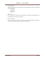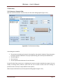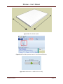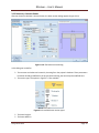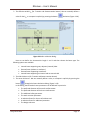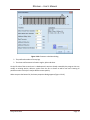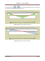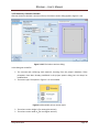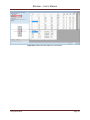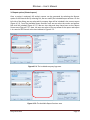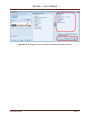
1
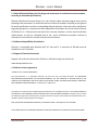
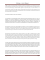
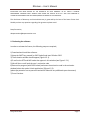
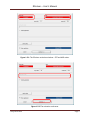
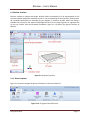
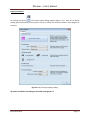
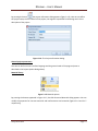
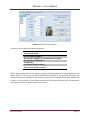
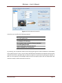
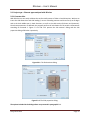
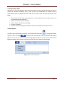
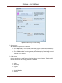
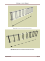
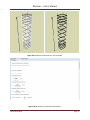
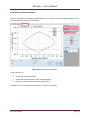
RCsolver – User’s Manual USER’ S MANUAL Eurocode design software program (Version 2012) Version 1.0 Issued: 19-Jun-2012 Deep Excavation LLC www.deepexcavation.com In collaboration through a research project with Aristotle University of Thessaloniki Deep Excavation Page 1 RCsolver – User’s Manual Table of Contents CHAPTER 1: INTRODUCTION TO RCsolver .................................................................................................... 4 1.1 About RCsolver(Software for the design and assessment of reinforced concrete members according to Eurocode specifications) ...................................................................................................... 5 1.2 Software Compatibility & Installation ................................................................................................. 5 1.3 Support & Technical Assistance .......................................................................................................... 5 1.4 End User License Agreement .............................................................................................................. 5 1.5 Activating the software ....................................................................................................................... 8 CHAPTER 2: USING RCsolver ....................................................................................................................... 10 2.1 RCsolver interface ............................................................................................................................. 11 2.1.1. General options......................................................................................................................... 11 2.1.2 General project parameters....................................................................................................... 17 2.1.3 Sections ...................................................................................................................................... 17 2.1.4 Tree view .................................................................................................................................... 18 2.1.5 Calculation button...................................................................................................................... 18 2.1.6 3D Model.................................................................................................................................... 18 2.1.7 View options toolbar.................................................................................................................. 19 2.2. Project type – Element types analyzed with RCsolver ..................................................................... 20 2.2.1 Concrete slabs ............................................................................................................................ 20 2.2.Concrete beams ............................................................................................................................ 21 2.2. C. Concrete columns .................................................................................................................... 22 CHAPTER 3: DESIGN PROJECTS USING RCsolver ........................................................................................ 23 3.1 Project design steps .......................................................................................................................... 24 3.2 Start project ...................................................................................................................................... 24 3.3 Data entry ......................................................................................................................................... 27 3.3.1 Data entry: Concrete Slabs......................................................................................................... 27 3.3.2 Data entry: Concrete Beams ...................................................................................................... 30 3.3.3 Data entry: Concrete Columns ................................................................................................... 36 3.4 Results overview in RCsolver ............................................................................................................ 41 3.4.1 Results: Concrete Slabs .............................................................................................................. 41 Deep Excavation Page 2 RCsolver – User’s Manual 3.4.2 Results: Concrete Beams............................................................................................................ 43 3.4.3 Results: Concrete Columns ........................................................................................................ 46 3.4.4 Results: Interaction diagram ...................................................................................................... 48 3.5 Report options (Printed reports) ...................................................................................................... 50 Deep Excavation Page 3 RCsolver – User’s Manual CHAPTER 1: INTRODUCTION TO RCsolver Deep Excavation Page 4 RCsolver – User’s Manual 1.1 About RCsolver(Software for the design and assessment of reinforced concrete members according to Eurocode specifications) RCsolver (Reinforced Concrete Solver) is a user friendly robust software program that permits the design and assessment of reinforced concrete structural members according to the general Eurocode specifications and the corresponding National Annexes, a fact that can be valuable for engineering projects in countries that have adopted the Eurocodes. One of the distinct features of RCsolver is its 3-Dimensional overview of the concrete members and the tensile and shear reinforcement, as well as a detailed flow of the entire calculation procedure inclusive of references to the relevant Eurocode clauses and the literature. 1.2 Software Compatibility & Installation RCsolver is compatible with Windows (OS) XP, Vista and 7. A minimum of 380 Mb must be available on user’s hard disk. 1.3 Support & Technical Assistance Support and technical assistance for RCsolver is offered through our web site at: www.deepexcavation.com 1.4 End User License Agreement "TERMS OF USE / LICENSE AGREEMENT" This legal document is an agreement between you (the end user) and Deep Excavation. BY CONTINUING WITH/OPENING/DOWNLOADING THIS SOFTWARE PROGRAM, YOU ARE AGREEING TO BECOME BOUND BY THE TERMS OF THIS AGREEMENT, WHICH INCLUDES THE SOFTWARE LICENSE, SOFTWARE DISCLAIMER OF WARRANTY, AND HARDWARE LIMITED WARRANTY "collectively the "Agreement". This agreement constitutes the complete agreement between you and Deep Excavation. IF YOU DO NOT AGREE TO THE TERMS OF THIS AGREEMENT, DO NOT CONTINUE WITH THIS SOFTWARE PROGRAM. Promptly return or delete the software program (cd and jewel case) and other items that are part of this product to Deep Excavation, for a complete refund if a purchasing fee was charged. DEEP EXCAVATION ENGINEERING PROGRAM, “SOFTWARE LICENSE", APPLICABLE TO ALL VERSIONS THE LICENSE APPLIES TO PURCHASED AND FREE OF PURCHASE VERSIONS OF THE DEEP EXCAVATION SOFTWARE. Deep Excavation Page 5 RCsolver – User’s Manual LICENSE. In consideration of payment of the LICENSE fee, which is a part of the price you paid for this product, Deep Excavation, as Licensor grants to you, the LICENSEE, a nonexclusive right to use and display this copy of Deep Excavation Engineering Program, Software (hereinafter referred to as "SOFTWARE" on a single COMPUTER (i.e., with a single CPU) at a single location. Any "networking", namely operating this program on a "network" is strictly forbidden. You as a Licensee are strictly forbidden to operate, utilize, transfer, distribute, connect, network, link to, attach, or operate in any manner this software on the internet, worldwide web, via email, any website, networking, any multimedia device, electronic or otherwise or any form of electronic media whatsoever. This includes but is not limited to the written materials, results, output, or resulting answers and/or printed matter without the prior written consent of Deep Excavation. Deep Excavation reserves all rights not expressly granted to LICENSEE. SOFTWARE OWNERSHIP. As the LICENSEE, you own the magnetic or other physical media on which the SOFTWARE is originally or subsequently recorded or fixed, however, Deep Excavation retains title and ownership of the SOFTWARE recorded on the original disk copy(ies) and any subsequent copies of the SOFTWARE, regardless of the form or media in or on which the original and other copies may exist. This License is not a sale of the original SOFTWARE or any copy thereof. COPY AND/OR MODIFY RESTRICTIONS. All Licensed Products are copyrighted and may not be further copied, without the prior written approval of Deep Excavation except that You may make one copy for backup purposes provided You reproduce and include the complete copyright notice, disclaimer, etc., on the backup copy. Any unauthorized copying is in violation of this Agreement and also a violation of the United States Copyright law. You may not use, transfer, modify, copy of otherwise reproduce the License Product, or any part of it, except as expressly permitted in this End User License Agreement. USE RESTRICTIONS. As the LICENSEE, you may physically transfer the SOFTWARE from one computer to another provided that the SOFTWARE is used on only one computer at a time. You may not electronically transfer the SOFTWARE from one computer to another over a network. You may not distribute copies of the SOFTWARE or accompanying written materials to others. You may not operate, utilize, transfer, distribute, connect, network, link to, attach, or operate in any manner this software on the internet, worldwide web, via email, any website, networking, any multimedia device, electronic or otherwise or any form of electronic media whatsoever. You may not modify, adapt, translate, reverse engineer, decompile, disassemble, or create derivative works based on the SOFTWARE. In addition, you may not modify, adapt, translate, or create derivative works based on the written materials, results, output, or resulting answers and/or printed matter without the prior written consent of Deep Excavation. RESTRICTIONS AGAINST TRANSFER. This SOFTWARE is licensed only to you, the LICENSEE, and may not be transferred to anyone without the prior written consent of DEEP EXCAVATION. Any authorized transferee of the SOFTWARE shall be bound by the terms and conditions of this Agreement. In no event may you transfer, assign, copy, rent, lease, sell, or dispose of the SOFTWARE in any manner on a temporary or permanent basis except as expressly provided herein. Deep Excavation Page 6 RCsolver – User’s Manual TERM. This End User License Agreement is effective from the date of purchase by You or granting to you of the Licensed Product and shall remain in force until terminated. You may terminate this End User License Agreement at any time by destroying the Licensed Product together with any backup copy in any form made by You or received by You. In addition, your right to use the Licensed Product will terminate if You fail to comply with any of the terms or conditions of this End User License Agreement. Upon such termination You shall destroy the copies of the Licensed Product in your possession. DISCLAIMER OF WARRANTY AND LIMITED WARRANTY THE SOFTWARE AND ACCOMPANYING WRITTEN MATERIALS (INCLUDING RESTRICTIONS FOR USE) IF ANY, ARE PROVIDED "AS IS" WITHOUT WARRANTY OF ANY KIND. FURTHER, DEEP EXCAVATION DOES NOT WARRANT, GUARANTEE, OR MAKE ANY REPRESENTATIONS REGARDING THE USE, OR THE RESULTS OF THIS USE, OF THE SOFTWARE OR WRITTEN MATERIALS IN TERMS OF CORRECTNESS, ACCURACY, RELIABILITY, CURRENTNESS, OR OTHERWISE. THE ENTIRE RISK AS TO THE RESULTS AND PERFORMANCE OF THE SOFTWARE IS ASSUMED BY YOU . Deep Excavation warrants to the original LICENSEE (a) the disk(s) on which the SOFTWARE is recorded to be free from defects in materials and workmanship under normal use and service for a period of sixty (60) days from the date of delivery as evidenced by a copy of the receipt. In addition, Deep Excavation hereby limits the duration of any implied warranty(ies) on the disk or such hardware to the respective period stated above. Deep Excavation's entire liability and your exclusive remedy as to the disk(s) or hardware shall be, at Deep Excavation's option, either (1) return of the purchase price or (2) replacement of the disk or hardware that does not meet Deep Excavation's Limited Warranty and which is returned to Deep Excavation with a copy of the receipt. If failure of the disk or hardware has resulted from accident, abuse or misapplication, Deep Excavation shall have no responsibility to replace the disk or hardware or refund the purchase price. Any replacement disk or hardware will be warranted for the remainder of the original warranty period or thirty (30) days, whichever is longer. THE ABOVE ARE THE ONLY WARRANTIES OF ANY KIND, EITHER EXPRESS OR IMPLIED, INCLUDING BUT NOT LIMITED TO THE IMPLIED WARRANTIES OR MERCHANTABILITY AND FITNESS FOR A PARTICULAR PURPOSE THAT ARE MADE BY DEEP EXCAVATION ON THIS PRODUCT. NO ORAL OR WRITTEN INFORMATION OR ADVICE GIVEN BY DEEP EXCAVATION, ITS DEALERS, DISTRIBUTORS, AGENTS, OR EMPLOYEES SHALL CREATE A WARRANTY OR IN ANY WAY INCREASE THE SCOPE OF THIS WARRANTY, AND YOU MAY NOT RELY ON ANY SUCH INFORMATION OR ADVICE. NEITHER DEEP EXCAVATION NOR ANYONE ELSE WHO HAS BEEN INVOLVED IN THE CREATION, PRODUCTION, OR DELIVERY OF THIS PRODUCT SHALL BE LIABLE FOR ANY DIRECT, INDIRECT, CONSEQUENTIAL, OR INCIDENTAL DAMAGES (INCLUDING DAMAGES FOR LOSS OF BUSINESS PROFITS, BUSINESS INTERRUPTION, LOSS OF BUSINESS INFORMATION, AND THE LIKE) ARISING OUT OF THE USE OF OR INABILITY TO USE SUCH PRODUCT EVEN IF DEEP Deep Excavation Page 7 RCsolver – User’s Manual EXCAVATION HAS BEEN ADVISED OF THE POSSIBILITY OF SUCH DAMAGES. IN ALL CASES A LICENCED PROFESSIONAL ENGINEER SHALL APPROVE AND STAMP ANY RESULTS BY D.E.E.P. AND THAT ENGINEER IS ULTIMATELY RESPONSIBLE FOR ANY CONSEQUENCES OR MISUSE OF THE SOFTWARE. This Disclaimer of Warranty and Limited Warranty is governed by the laws of the State of New York. Should you have any questions regarding this agreement please email: Deep Excavation, [email protected] 1.5 Activating the software In order to activate the license, the following steps are required; 1) Download and install the software. 2) Keep the SHIFT key pressed (or CAPS locked) and start RCsolver 2012 3) The activation window should appear (Figure 1.5.1). 4) E-mail us the SITE and MID codes that appear in this window (see Figure 1.5.1). 5) We will then e-mail back the user’s activation code 6) Restart the program (with CAPS locked) and enter the activation code in the activation window (select the option Unlock application) (Figure 1.5.2). (please pay attention not to paste the activation code with any additional space characters) 7) Press Continue. Deep Excavation Page 8 RCsolver – User’s Manual Figure 1.5.1: The RCsolver activation window – SITE and MID codes. Figure 1.5.2: The activation code area. Deep Excavation Page 9 RCsolver – User’s Manual CHAPTER 2: USING RCsolver Deep Excavation Page 10 RCsolver – User’s Manual 2.1 RCsolver interface RCsolver interface is modern and unique. RCsolver offers the possibility of a 3D representation of the concrete member designed or assessed as well as the corresponding tensile and shear reinforcement. All calculations performed are described by the program in maximum possible detail thus being a valuable tool not only for the experienced designer but also for the young engineers or engineers that are not yet familiar with the Eurocodes framework. Figure 2.1.1 presents the general interface of RCsolver. Figure 2.1.1: General interface. 2.1.1. General options Figure 2.1.2 presents the general options of RCsolver on the main ribbon bar. Figure 2.1.2: The general tab of RCsolver. Deep Excavation Page 11 RCsolver – User’s Manual Project parameters: By pressing the button , the Project options dialog appears (Figure 2.1.3). Here we can define several general parameters of the project, as well as choose the structural member to be designed or assessed. Figure 2.1.3: The Project Options dialog. All options included in this dialog are described in paragraph 3.2. Deep Excavation Page 12 RCsolver – User’s Manual By pressing the button , the project information dialog appears (Figure 2.1.4). Here we can define the project name, the file number of the project, the engineer responsible for the design and a short description of the project. Figure 2.1.4: The Project Information dialog. General project parameters: Here we can define the user interface language and the general mode of the program (same as described in the Project Options dialog above). Material library: Figure 2.1.5: Material options. By pressing the buttons appeared in Figure 2.1.5, the Edit Structural Materials dialog appears. We can modify the properties for concrete materials and reinforcement steel materials (Figures 2.1.6 and 2.1.7 respectively). Deep Excavation Page 13 RCsolver – User’s Manual Figure 2.1.6: Edit concrete materials. In this form we can define the following properties: The material name The concrete strength fc The tension strength ft (% of compressive strength) The modulus of elasticity E The density g The rapture strain of steel eRu The concrete strains εc2 and εc3 We can add new materials from the program’s general material database to the partial database of the specific project. To do so, we can choose the Reference Standard for the materials and choose the materials from the list provided. We can choose to import the new material replacing the selected one, or add it as a new material in the available materials list for the specific project. We can always add a new material manually or delete materials from the list. Deep Excavation Page 14 RCsolver – User’s Manual Figure 2.1.7: Edit rebar steel materials. In this form we can define the following properties: The steel grade name The yield strength fy The modulus of elasticity E The standard rebar material reference standard The steel material used Import and replace selected material Import and add as a new material As previously, we can add new materials from the programs general material database to the database of the specific project. To do so, we can choose the Reference Standard for the materials and choose the materials from the list provided. We can choose to import the new material replacing the selected, or add it as a new material in the available materials list for the specific project. We can always add a new material manually or delete materials from the list. Deep Excavation Page 15 RCsolver – User’s Manual Advanced: By pressing the button , the Advanced options dialog appears (Figure 2.1.8). Figure 2.1.8: The advanced options dialog. Here we can define the rapture strain of steel eRu. The program provides the following options: The eRu is determined directly according to the code standards (i.e., the corresponding National Annexes of the Eurocodes) The eRu is determined for each concrete material User defined eRu Deep Excavation Page 16 RCsolver – User’s Manual Reports: By pressing the button, the report options dialog appears (Figure 2.1.9). Here we can choose which sections should be included in the report, we can preview the report and we can choose to export it in MSWord or pdf format. The options included in this dialog are presented in paragraph 3.5. Figure 2.1.9: The report options dialog. 2.1.2 General project parameters Here we can see the applicable Eurocode part and the National Annex selected, the problem type and the partial loading factors γconc and γsteel as well as the rapture strain of steel eRu. 2.1.3 Sections Here we can see the sections of the structural members that are designed or assessed, and change its properties by double clicking. Deep Excavation Page 17 RCsolver – User’s Manual 2.1.4 Tree view RCsolver offers features that include a tree-style project view. The tree view enables the user to quickly access vital project data, as well as visualize crucial project settings. The next table briefly describes the functionality of the Tree View items. Shows available structural materials Shows all concrete and reinforcement steel materials included in the programs database. It is recalled that we can always create or add new materials. Shows the available structural sections for the selected project Shows the available Structural members for the selected project 2.1.5 Calculation button By pressing the button , the program performs all the necessary calculations according to the selected codes and the defined loading. 2.1.6 3D Model In this area, the model is generated in 3D, after the project type, section properties and structural member loading pattern is defined. We can rotate the model, zoom in and out and view model dimensions and loading diagrams. After the calculation is completed we can view the member reinforcement in 3D on the model. Deep Excavation Page 18 RCsolver – User’s Manual 2.1.7 View options toolbar A vertical toolbox is available on the right screen side. The available tools are described in the table below: Tool ISO Description Changes between isometric and realistic modes of RCsolver 3D visualization Pan – click to move 3D model into the area without rotation Snapshot – click to take a quick snapshot of the screen Top view of the 3D model Side view of the 3D model Front view of the 3D model Show concrete and reinforcement in the 3D model (after the calculation is completed) Show only concrete in the 3D member Show only reinforcement in the 3D member Zoom in Zoom out Restore model to the center of the screen Show/hide outlines of model in the 3D model Show/hide dimensions in the 3D model Show/hide global axis in the 3D model Show/hide moment diagram in the 3D model Show/hide shear diagram in the 3D model Show/hide axial force diagram in the 3D model Deep Excavation Page 19 RCsolver – User’s Manual 2.2. Project type – Element types analyzed with RCsolver 2.2.1 Concrete slabs With RCsolver we can easily calculate the tensile reinforcement of slabs on both directions. We have to insert the slab dimensions and slab loading (in terms of bending moment and shear force) at all edges and at the slab middle span in both directions, as well as the slab section (thickness and clearance). Once these parameters are defined, the program performs all calculations for the tensile reinforcement according to Eurocode 2.. Figure s 2.2.1 and 2.2.2 present the slab sections’ dialog and the slab properties dialog of RCsolver respectively. Figure 2.2.1: The Slab sections dialog. Figure 2.2.2: The Slab properties dialog. The options included in the dialogs above are presented in paragraph 3.3.1. Deep Excavation Page 20 RCsolver – User’s Manual 2.2.2 Concrete beams With RCsolver we can easily calculate required the tensile and shear reinforcement of concrete beams according to Eurocode specifications for a given loading pattern. We have to insert the beam dimensions and beam loading (bending moment and shear force) at the edges and span of the beam, as well as the beam section (in terms of the section type, its dimensions, the clearance and preferred longitudinal and shear reinforcement bar diameters). Then, the program performs all necessary calculations prescribed in Eurocode 2. Figure s 2.2.3 and 2.2.4 present the beam sections dialog and the beam properties dialog of RCsolver respectively. Figure 2.2.3: The Beam sections dialog. Figure 2.2.4: The Beam properties dialog. The options included in the dialogs above are presented in paragraph 3.3.2. Deep Excavation Page 21 RCsolver – User’s Manual 2.2. C. Concrete columns With RCsolver we can easily calculate the tensile and shear reinforcement of concrete columns according to Eurocode specifications. We have to insert the column dimensions and column loading (bending moments, shears and axial forces) for the top and bottom edge of the column, as well as the column section (section type, dimensions, clearance and preferred longitudinal and shear reinforcement bar diameters). Then, the program performs all necessary calculations prescribed in Eurocode 2.. Figures 2.2.5 and 2.2.6 present the column sections dialog and the column properties dialog of RCsolver respectively. Figure 2.2.5: The Column sections dialog. Figure 2.2.6: The Column properties dialog. The options included in the dialogs above are presented in paragraph 3.3.3. Deep Excavation Page 22 RCsolver – User’s Manual CHAPTER 3: DESIGN PROJECTS USING RCsolver Deep Excavation Page 23 RCsolver – User’s Manual 3.1 Project design steps In RCsolver, we can easily design or assess concrete members. The user-friendly interface, the ability to review the calculation procedure step by step and the 3D representation of members and its reinforcement make the program RCsolver unique. We can easily create a project following the steps below: Start project: Define basic project parameters, Code, National Annex, member type to be analyzed and material properties. Define structural sections of members. Define member dimensions and loading. Perform calculations. Produce a report containing all calculations made and a detailed overview of the results. 3.2 Start project In order to start a new project in RCsolver, we can either press the button in the General RCsolver ribbon, or press the button and then choose “New project” from the window that appears (Figure 3.2.1). In this case, the Project options dialog appears (Figure 3.2.2). Here we can define several general parameters of the project, as well as choose the structural member to be analyzed. Figure 3.2.1: Create new project. Deep Excavation Page 24 RCsolver – User’s Manual Figure 3.2.2: The Project Options dialog. General mode: We can define analysis modes in RCsolver: The Design mode of a new member, where the program will determine automatically the required reinforcement based on the design loads and the Eurocode 2 provisions. The Analysis mode of an existing member, where the capacity of an existing structural member will be assessed. Code options: Here we can choose the code framework and the National Annex to be used. The Eurocode 2 National Annexes for the following countries are included: Greece Italy Germany Cyprus France United Kingdom Austria Deep Excavation Page 25 RCsolver – User’s Manual Structural member: Here we can choose the structural member to be analyzed (designed or assessed). The following options are available: Single beam Single column Single slab Ductility class: Here we can define the ductility class for the project. It is recalled, that only low ductility class is permitted for Eurocode 2 analysis calculations. Structural materials: Here we can predefine the concrete and reinforcement steel materials to be used in the project. We can always change and add new materials from the database. Deep Excavation Page 26 RCsolver – User’s Manual 3.3 Data entry 3.3.1 Data entry: Concrete Slabs After we choose to calculate a concrete slab, the slab section dialog appears (Figure 3.3.1). Figure 3.3.1: The Slab sections dialog. In this dialog we can define: The concrete and rebar steel materials, choosing from the project’s database. These parameters have been already predefined in the project options dialog, but can always be modified here. The slab height hf. The clearance c. The user-preferred bar diameters for each direction. On the left side of the screen there is a database with sections already created by the program. We can modify an existing section, delete a section from the list or choose to add a new one. Creating all possible sections can help us analyze different cases quickly. When we press the button OK, the slab properties dialog appears (Figure 3.3.2). Deep Excavation Page 27 RCsolver – User’s Manual Figure 3.3.2: The Slab properties dialog. In this dialog we can define: The slab section to be used (from the sections that we have previously created). By pressing the button we are guided to the slab sections dialog. The slab dimensions Lx and Ly. The slab loading. We can define the action effects (bending moment and shear forces) directly at all slab edges and the middle of the slab span. Bear in mind that positive values are used for bottom tensile strain. The support conditions of the slab. By pressing the buttons around the slab we can define whether the specific edge is fixed or free. Choosing a free boundary condition, the internal forces along the particular edge will be automatically set to zero. When we press the button OK in this dialog, the program automatically generates a 3D model of the slab (Figure 3.3.3). We can easily access and modify the slab properties by pressing the button in the Slab tab of RCsolver that appears on top (Figure 3.3.4), or by double clicking the slab element in the tree view on the left. In order to modify the slab section properties, we can double click on the section drawing on the left side of main screen as well (Figure 3.3.5). Deep Excavation Page 28 RCsolver – User’s Manual Figure 3.3.3: The Slab 3D model. Figure 3.3.4: The Slab properties button in the slab tab of RCsolver. Figure 3.3.5: Slab section – double click to modify. Deep Excavation Page 29 RCsolver – User’s Manual 3.3.2 Data entry: Concrete Beams After we choose to calculate a concrete beam, the beam section dialog appears (Figure 3.3.6). Figure 3.3.6: The Beam sections dialog. In this dialog we can define: The concrete and rebar steel materials, choosing from the project’s database. These parameters have been already predefined in the project options dialog, but can always be modified here. The section type. The options in figure 3.3.7 are available. Figure 3.3.7: Available beam section types. The beam height h. The beam width bw. Deep Excavation Page 30 RCsolver – User’s Manual The effective width beff (for T-section and Gamma-section beams). We can manually define a value for the beff, or compute it explicitly by pressing the button calculation (Figure 3.3.8). Figure 3.3.8: Beff calculation dialog. Here we can define the characteristic length l1 and l2 and then choose the beam type. The following options are available: Internal beam supporting two, adjacent (internal) slabs. External beam (without a cantilever). External beam supporting a cantilever. Internal beam supporting an internal and an external slab. The slab thickness tf (for T-section and Gamma-section beams). The cover thickness c. We can manually define a value, or compute it explicitly by pressing the button through the Cover calculation dialog (Figure 3.3.9). In this dialog, the Eurocode 2 cover parameters can be defined. In particular: The preferred diameter of the tensile reinforcement. The preferred diameter of the shear reinforcement. The additional safety parameter. The steel corrosion parameter. A reduction factor for the use of stainless steel A reduction factor for additional protection The design tolerance Deep Excavation Page 31 RCsolver – User’s Manual Figure 3.3.9: Clearance calculation dialog. The preferred number of stirrup legs. The shear reinforcement inclination angles, alpha and theta. On the left side of the screen there is a database with sections already created by the program. We can modify an existing section, delete a section from the list or choose to add a new one. Creating all possible sections can help us analyze different cases quickly. When we press the button OK, the beam properties dialog appears (Figure 3.3.10). Deep Excavation Page 32 RCsolver – User’s Manual Figure 3.3.10: Beam properties dialog. In this dialog we can define: The beam section to be used (from the sections that we have previously created). By pressing the button we are guided to the beam sections dialog. The beam length L. The beam loading pattern (i.e., bending moments and shear force at the edges of the beam and the span middle). Bear in mind that positive values are used for bottom tensile strain. When we press the button OK in this dialog, the program automatically generates a 3D model of this beam (Figure 3.3.11) inclusive of its effective width, as it has been already defined or computed. We can easily access and modify the beam properties by pressing the button in the Beam tab of RCsolver that appears on top (Figure 3.3.12), or by double clicking the beam element in the tree view. In order to modify the beam section properties, we can double click on the section drawing on the left side of main screen (Figure 3.3.13). Deep Excavation Page 33 RCsolver – User’s Manual Figure 3.3.11: Beam 3D model. Figure 3.3.12: The Beam properties button in the beam tab of RCsolver. Figure 3.3.13: Beam section – double click to modify. Deep Excavation Page 34 RCsolver – User’s Manual By pressing the buttons and we can see the Bending Moment and Shear Force diagrams on the 3D model respectively (Figures 3.3.14 and 3.3.15). Figure 3.3.14: Beam moment diagram on 3D model. Figure 3.3.15: Beam shear diagram on 3D model. Deep Excavation Page 35 RCsolver – User’s Manual 3.3.3 Data entry: Concrete Columns After we choose to calculate a concrete column, the column section dialog appears (Figure 3.3.16). Figure 3.3.16: The Column sections dialog. In this dialog we can define: The concrete and reinforcing steel materials, choosing from the project’s database. These parameters have been already predefined in the project options dialog, but can always be modified here. The section type. The options in figure 3.3.17 are available. Figure 3.3.17: Available column section types. The column section height h (for rectangular sections). The column section width bw (for rectangular sections). Deep Excavation Page 36 RCsolver – User’s Manual The cover thickness c. We can manually define a value, or by pressing the button described in paragraph 3.3.2. The user-preferred bar diameters for longitudinal and shear reinforcement. The number of stirrup legs. The shear reinforcement inclination angles alpha and theta. as On the left side of the screen there is a database with sections already created by the program. We can modify an existing section, delete a section from the list or choose to add a new one. Creating all possible sections can help us analyze different cases quickly. When we press the button OK, the column properties dialog appears (Figure 3.3.18). Figure 3.3.18: Column properties dialog. In this dialog we can define: The column section to be used (from the sections that we have previously created). By pressing the button we are leaded to the column sections dialog. The column height H. The column top and bottom internal forces (in terms of moment, shear and axial force). Bear in mind that positive axial force is used for compression. Deep Excavation Page 37 RCsolver – User’s Manual When we press the button OK in this dialog, the program automatically generates a 3D model of this column (Figure 3.3.19). We can easily access and modify the column properties by pressing the button in the Column tab of RCsolver that appears on top (Figure 3.3.20), or by double clicking the column element in the tree view. In order to modify the column section properties, we can double click on the section drawing on the left side of main screen (Figure 3.3.21). Figure 3.3.19: Column 3D model. Figure 3.3.20: The Column properties button in the column tab of RCsolver. Deep Excavation Page 38 RCsolver – User’s Manual Figure 3.3.21: Column section – double click to modify. By pressing the buttons , and we can visualize the Bending Moment, Shear and Axial force diagrams on the 3D model respectively (Figures 3.3.22, 3.3.23 and 3.3.24). Figure 3.3.22: Column moment diagram on 3D model. Deep Excavation Page 39 RCsolver – User’s Manual Figure 3.3.23: Column shear diagram on 3D model. Figure 3.3.24: Column axial force diagram on 3D model. Deep Excavation Page 40 RCsolver – User’s Manual 3.4 Results overview in RCsolver 3.4.1 Results: Concrete Slabs After the calculation is completed we can graphically visualize the results in the corresponding tab of RCSOLVER (Figure 3.4.1). Here we can see the slab plan with the reinforcement. On the right side of the screen we can see a table summarizing all reinforcement bars with their lengths and orientation. Figure 3.4.1: Slab graphical results. In the 3D model tab we can graphically see the reinforcement inserted in the model (Figure 3.4.2). Finally, in the Calculations tab of RCsolver we can see all Eurocode 2 calculations for the analysis of the slab on both directions and the calculation of the provided longitudinal reinforcement (Figure 3.4.3). Deep Excavation Page 41 RCsolver – User’s Manual Figure 3.4.2: Slab reinforcement in 3D space. Figure 3.4.3: Slab reinforcement calculations. Deep Excavation Page 42 RCsolver – User’s Manual 3.4.2 Results: Concrete Beams After the calculation is completed we can graphically see the results in the Results tab of RCsolver(Figure 3.4.4). Here we can see the beam plan with the reinforcement. On the right side of the screen we can see a table, summarizing all reinforcement bar details, inclusive of their lengths. At the bottom of the screen we can see characteristic cross-sections (i.e., left and right beam edge and span middle). Figure 3.4.4: Beam graphical results. In the 3D model tab we can graphically see the reinforcement inserted in the model (Figure 3.4.5). By pressing the button we can see the reinforcement on the 3D model without the concrete member (Figure 4.4.6). Finally, in the Calculations tab of RCsolver we can review all Eurocode 2 calculations for the analysis of the beam and the calculation of the required and provided longitudinal and shear reinforcement (Figure 3.4.7). Deep Excavation Page 43 RCsolver – User’s Manual Figure 3.4.5: 3D layout of the reinforced concrete beam. Figure 3.4.6: 3D layout of the reinforced concrete beam reinforcement. Deep Excavation Page 44 RCsolver – User’s Manual Figure 3.4.7: Calculations log file for the case of the beam designed. Deep Excavation Page 45 RCsolver – User’s Manual 3.4.3 Results: Concrete Columns After the calculation is completed we can graphically visualize the results in the Results tab of RCsolver (Figure 3.4.8). Here we can see the column side view with the reinforcement and the top and bottom column sections. On the right side of the screen we can see a table, summarizing all reinforcement bar details, inclusive of their lengths Figure 3.4.8: Column graphical results. In the 3D model tab we can graphically visualize the required reinforcement computed (Figure 3.4.9). By pressing the button we can see the reinforcement on the 3D model without the concrete member. Finally, in the Calculations tab of RCsolver we can review all Eurocode 2 calculations for the analysis of the column and the calculation of the required and provided longitudinal and shear reinforcement (Figure 3.4.11). Deep Excavation Page 46 RCsolver – User’s Manual Figure 3.4.9: Column reinforcement in the 3D model. Figure 3.4.10: Column reinforcement calculations. Deep Excavation Page 47 RCsolver – User’s Manual 3.4.4 Results: Interaction diagram After the calculation is succeeded, the Bending Moment – Axial Load interaction diagram appears in the relevant tab on the main screen of RCsolver. Figure 3.5.1: M-N interaction diagram. In this tab user can: Choose the structural member Choose the structural section of the selected member Choose to show interaction table data (Figure 3.5.2) In addition, user can modify here the axis titles, as well as the font size. Deep Excavation Page 48 RCsolver – User’s Manual Figure 3.5.2: M-N interaction tables for each section. Deep Excavation Page 49 RCsolver – User’s Manual 3.5 Report options (Printed reports) Once a project is analyzed, full analysis reports can be generated by selecting the Reports option at the General tab. By selecting this, we can modify the included output sections. On the left side of the dialog, we can select which company logo will be included in the current report (Figure 4.5.1). From the Available Report Sections area, we can select the results and options that shall be included (Figure 4.5.2). We can also drag and drop these items at the Report Format area (Figure 4.5.3). Next, the user can select to see a preview of the report and export it in a word or PDF format at the area indicate in Figure 4.5.3. Figure 4.5.1: The included company logo area. Figure 4.5.2: The Available Report Sections area. Deep Excavation Page 50 RCsolver – User’s Manual Figure 4.5.3: The Report Format area and the preview and export buttons. Deep Excavation Page 51